WO2024252957A1 - コネクタカバー - Google Patents
コネクタカバー Download PDFInfo
- Publication number
- WO2024252957A1 WO2024252957A1 PCT/JP2024/019253 JP2024019253W WO2024252957A1 WO 2024252957 A1 WO2024252957 A1 WO 2024252957A1 JP 2024019253 W JP2024019253 W JP 2024019253W WO 2024252957 A1 WO2024252957 A1 WO 2024252957A1
- Authority
- WO
- WIPO (PCT)
- Prior art keywords
- pin
- receiving
- hole
- wiring
- cover
- Prior art date
- Legal status (The legal status is an assumption and is not a legal conclusion. Google has not performed a legal analysis and makes no representation as to the accuracy of the status listed.)
- Ceased
Links
Images



Classifications
-
- H—ELECTRICITY
- H01—ELECTRIC ELEMENTS
- H01R—ELECTRICALLY-CONDUCTIVE CONNECTIONS; STRUCTURAL ASSOCIATIONS OF A PLURALITY OF MUTUALLY-INSULATED ELECTRICAL CONNECTING ELEMENTS; COUPLING DEVICES; CURRENT COLLECTORS
- H01R13/00—Details of coupling devices of the kinds covered by groups H01R12/70 or H01R24/00 - H01R33/00
- H01R13/58—Means for relieving strain on wire connection, e.g. cord grip, for avoiding loosening of connections between wires and terminals within a coupling device terminating a cable
Definitions
- This disclosure relates to a connector cover.
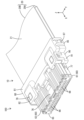
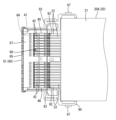
- FIG. 1 is an exploded perspective view of each member, excluding a wiring member, in a connector including a connector cover of a first embodiment.
- FIG. 2 is a perspective view of a connector including the connector cover of the first embodiment.
- FIG. 3 is a rear view of the connector including the connector cover of the first embodiment.
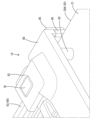
- FIG. 4 is an enlarged perspective view showing a portion where a hole-punching pin penetrates a sheet portion of a wiring member in the connector cover of the first embodiment.
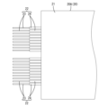
- FIG. 5 is a plan view of the wiring member in the connector cover of the first embodiment.
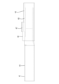
- FIG. 6 is a side view of a terminal fitting in the connector cover of the first embodiment.
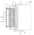
- FIG. 7 is a plan view showing a state in which a terminal fitting is accommodated in a first accommodating chamber of a first member in a connector including a connector cover of embodiment 1 and a conductor of a first wiring member is connected to the accommodated terminal fitting.
- Figure 8 is a plan view showing a state in which a terminal fitting is accommodated in the second accommodating chamber of the second member from the state shown in Figure 7 in a connector including a connector cover of embodiment 1, and a conductor of the second wiring member is connected to the accommodated terminal fitting.
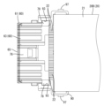
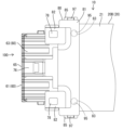
- 9 is a plan view showing a state in which a third member is attached to the connector including the connector cover of the first embodiment from the state shown in FIG. 8.
- the wiring member is held between the holding member and the receiving member by the hole-punching pin penetrating and holding the sheet portion. Furthermore, the locking portion of the hole-punching pin faces and can come into contact with the outer surface of the receiving member, preventing the holding member from being displaced in a direction opening from the receiving member. Because the hole-punching pin has both the function of holding the wiring member and the function of preventing the holding member from coming off the receiving member, the structure of the holding member and, by extension, the connector cover can be simplified compared to when each function is provided in a separate location on the holding member.
- the pin receiving portion has an inner peripheral edge on the inner surface of the receiving member that cuts through the sheet portion between the hole-punching pin and the inner surface of the receiving member.
- the locking portion has a slope that narrows toward the tip side in the insertion direction into the pin receiving portion, an end face located on the tip side, and a corner that connects the slope and the end face at an obtuse angle.
- Each split pin is elastically deformed during the process of insertion into the pin receiving portion, and can elastically return to its original state when insertion into the pin receiving portion is complete. As each split pin elastically returns to its original state, the locking portion is positioned facing and able to come into contact with the outer surface of the receiving member. This allows the pin body to be smoothly inserted into the pin receiving portion, while ensuring a sufficient locking allowance for the locking portion with respect to the receiving member.
- the connector cover 10 of the first embodiment is provided on the connector 100 shown in Figures 2 and 3.
- the connector 100 is configured to include the connector cover 10, the terminal fittings 40, and the housing 60 that accommodates the terminal fittings 40.
- the connector cover 10 includes the wiring members 20 connected to the terminal fittings 40, and the holding member 80 and the receiving member 90 that protect the wiring members 20 and are held by the housing 60.
- the front side is defined as the side where the connector 100 is mated with a mating connector (not shown).
- the up-down direction is based on the up-down direction in Figures 1 and 2.
- the arrows X, Y, and Z represent the front, right, and up, respectively. These directions do not necessarily coincide with the directional reference when the connector 100 is mounted on a vehicle (not shown) or the like.
- the wiring member 20 has a sheet portion 21 and a plurality of electric wires 22 fixed to the sheet portion 21.
- the sheet portion 21 is made of an insulating material, for example, a nonwoven fabric.
- An example of the electric wires 22 is a coated electric wire in which an outer periphery of a conductor 23, such as a core wire, is covered with an insulating coating 24.
- the multiple electric wires 22 are fixed to one surface of the sheet portion 21 (the lower surface in the case of this embodiment 1) in a state lined up in the left-right direction.
- Each electric wire 22 is fixed to one surface of the sheet portion 21 by, for example, a welding means.
- a welding means known welding means such as ultrasonic welding, heat and pressure welding, high frequency welding, etc. can be used.
- the wiring member 20 is flexible overall and has a flat rectangular shape in a plan view with a reduced height dimension.
- each electric wire 22 is disposed so as to protrude forward from the sheet portion 21.
- the front end of each electric wire 22 has the conductor 23 exposed by stripping off the coating 24 (hereinafter, the conductor exposed at the front end of each electric wire 22 is referred to as the "exposed conductor 23").
- the wiring member 20 has a first wiring member 20A arranged in the lower stage inside the connector 100 and a second wiring member 20B arranged in the upper stage.
- the number of each electric wire 22 fixed to the sheet portion 21 differs between the first wiring member 20A and the second wiring member 20B.
- the first wiring member 20A includes a portion in the left-right center portion of the sheet portion 21 where the electric wires 22 are not fixed, and accordingly, the number of each electric wire 22 is fewer than that of the second wiring member 20B.
- the number of each electric wire 22 may be the same in the first wiring member 20A and the second wiring member 20B, or, conversely, the first wiring member 20A may have more electric wires than the second wiring member 20B.
- the terminal fitting 40 includes a connection member 41 and a slide member 42 that is slidably attached to the connection member 41 between a spaced position and a connected position.
- the connection member 41 and the slide member 42 are separate from each other. Both the connection member 41 and the slide member 42 are formed by bending a conductive metal plate or the like.
- connection member 41 has a cylindrical, for example, rectangular, connection body 43.
- the connection body 43 receives a mating terminal fitting (not shown) from the front and is electrically connected.
- the connection member 41 also has a contact portion (not shown) that extends rearward from the connection body 43.
- the slide member 42 has a cylindrical, for example, square cylindrical, box portion 45.
- the contact portion of the connection member 41 is inserted into the box portion 45.
- the slide member 42 has a pressing portion (not shown) inside the box portion 45.
- the housing 60 is composed of a first member 61, a second member 62, and a third member 63.
- the first member 61, the second member 62, and the third member 63 are arranged in this order in a stacked state from the bottom up.
- the first member 61, the second member 62, and the third member 63 are all made of synthetic resin.
- the first member 61 is configured as a lower housing.
- the first member 61 is rectangular in plan view and is elongated in the left-right direction.
- the first member 61 has a plurality of first accommodating chambers 64 arranged in a row in the left-right direction on the upper surface side.
- Each first accommodating chamber 64 extends in the front-rear direction in the first member 61 and opens to the rear.
- the terminal fitting 40 is inserted from the rear into the first accommodating chamber 64 and accommodated therein.
- the first member 61 has a front wall 65 that constitutes the front portion of the housing 60.
- the front wall 65 has a plurality of terminal insertion holes 66 that communicate with the front openings of each of the first accommodating chambers 64 and each of the second accommodating chambers 71 described later.
- Each terminal insertion hole 66 is opened in two rows, one above the other, and in a row in the left-right direction.
- the mating terminal fitting (not shown) is connected to the terminal fitting 40 from the front of the housing 60 through the terminal insertion hole 66.
- the first member 61 has a flat first cover portion 67 that closes the upper surface of the front part of each first storage chamber 64.
- the connection member 41 of the terminal fitting 40 is accommodated in the front part of the first storage chamber 64, and the first cover portion 67 prevents the connection member 41 from slipping out upward.
- the first member 61 has a first exposed surface 68 that opens the upper surface of the rear part of each first storage chamber 64.
- the slide member 42 of the terminal fitting 40 is accommodated in the rear part of the first storage chamber 64, and is exposed upward by the first exposed surface 68. When a part of the slide member 42 exposed on the first exposed surface 68 (see the protrusion 47 in FIG. 6) is pressed forward, the slide member 42 is moved from the separated position to the connected position.
- the first member 61 has a pair of first housing lock portions 69 that protrude upward at both left and right ends.
- the second member 62 is configured as an inner housing. As shown in FIG. 1 and FIG. 8, the second member 62 has a rectangular shape in a plan view that is slightly smaller than the first member 61, and is formed long in the left-right direction. The lower surface of the second member 62 covers the upper surface of the first member 61 and closes the first exposed surface 68.
- the second member 62 has a plurality of second accommodating chambers 71 arranged in a row in the left-right direction on the upper surface side. Each second accommodating chamber 71 extends in the front-rear direction in the second member 62 and is open to the rear.
- the terminal fitting 40 is inserted from the rear into the second accommodating chamber 71 and accommodated therein.
- the second member 62 has a flat second cover portion 72 that closes the upper surface of the front part of each second accommodating chamber 71, and has a second exposed surface 73 that opens the upper surface of the rear part of each second accommodating chamber 71.
- the functions of the second cover portion 72 and the second exposed surface 73 are similar to those of the first cover portion 67 and the first exposed surface 68 described above.
- the second member 62 has a pair of second housing locking parts 74 at both the left and right ends. Each second housing locking part 74 is engaged with each first housing locking part 69 from the inside, thereby holding the second member 62 to the first member 61.
- the third member 63 is configured as an upper housing. As shown in FIG. 1 and FIG. 9, the third member 63 is rectangular in plan view, slightly larger than the first member 61, and is formed long in the left-right direction. The lower surface of the third member 63 covers the upper surface of the second member 62 and closes the second exposed surface 73.
- the third member 63 has a plurality of housing grooves 75 (see FIG. 3) connected to the rear end of the lower surface.
- the housing grooves 75 are arranged in a row in the left-right direction at positions corresponding to the second storage chambers 71.
- the housing grooves 75 have a U-shaped cross section and open downward.
- the housing grooves 75 are arranged behind the first member 61 and the second member 62.
- the electric wires 22 of the second wiring member 20B are inserted into the housing grooves 75 from below.
- the third member 63 has an elastically deformable lock arm 76 in the left-right center of the top surface.
- the lock arm 76 locks the mating connector and holds the connector 100 and the mating connector in a mated state.
- the third member 63 has a pair of third housing locking portions 77 protruding downward at both left and right ends. Each third housing locking portion 77 is externally engaged with each first housing locking portion 69, thereby holding the third member 63 in a stacked state relative to the first member 61 and the second member 62.
- the third member 63 has a pair of locking projections 78 at both left and right ends and at the rear end behind each third housing locking portion 77.
- Each locking projection 78 has a rectangular column shape extending in the vertical direction and is disposed behind each of the first member 61 and the second member 62 when the first member 61, the second member 62, and the third member 63 are in a stacked state.
- the receiving member 90 is configured as a lower cover.
- the receiving member 90 is made of synthetic resin, has a rectangular shape in a plan view, and is formed long in the left-right direction. As shown in FIG. 7, the receiving member 90 is arranged in line with the first member 61 behind the first member 61.
- the receiving member 90 has a flat receiving body 91.
- the receiving member 90 has a plurality of cover grooves 92 connected to the front end of the receiving body 91.
- the cover grooves 92 are arranged in a row in the left-right direction at positions corresponding to the first storage chambers 64.
- the cover grooves 92 have a U-shaped cross section and open upward.
- the electric wires 22 of the first wiring member 20A are inserted into the cover grooves 92 from above.
- the cover grooves 92 and the housing grooves 75 are misaligned with each other in the width direction.
- the receiving member 90 has a pair of first receiving portions 93 at the front end of the receiving body 91, on both the left and right ends sandwiching each cover groove portion 92.
- Each first receiving portion 93 has a rectangular concave cross section and is open upward. The lower portion of each locking protrusion 78 is fitted into each first receiving portion 93 from above in a positioned state (see FIG. 9).
- the receiving member 90 has a flat opposing surface 94 facing the wiring member 20 behind each of the cover grooves 92 and each of the first receiving portions 93 on the upper surface of the receiving body 91.
- the receiving member 90 has a pair of pin receiving portions 95 at both the left and right ends of the receiving body 91 and behind each of the first receiving portions 93.
- Each pin receiving portion 95 is a hole with a circular cross section, penetrates the receiving body 91 in the vertical direction (thickness direction), and opens on the opposing surface 94 and the lower surface of the receiving body 91.
- each pin receiving portion 95 opening on the opposing surface 94 has an edge shape without chamfering, and is configured as a scraping edge 96 that can scrape the sheet portion 21 between the hole punching pin 83 described later.
- the receiving member 90 also has a pair of first cover locking portions 97 that protrude upward from both the left and right ends of the receiving body 91.
- the holding member 80 is configured as an upper cover.
- the holding member 80 is made of synthetic resin, has a rectangular shape in a plan view, and is formed long in the left-right direction. As shown in FIG. 10, the holding member 80 is arranged in line with the third member 63 behind the third member 63. As shown in FIG. 3, the holding member 80 is arranged facing the receiving member 90 with the first wiring member 20A and the second wiring member 20B sandwiched between them.
- the holding member 80 has a flat plate-shaped holding body 81.
- the holding member 80 has a pair of second receiving portions 82 that protrude forward from both the left and right sides of the holding body 81. Each second receiving portion 82 has a rectangular frame shape. The upper portion of each locking protrusion 78 is fitted into each second receiving portion 82 from below in a positioned state (see FIG. 10).
- the underside of the holding body 81 is formed flat.
- the holding member 80 has a pair of hole-punching pins 83 protruding from the rear of each second receiving portion 82 on both the left and right sides of the underside of the holding body 81.
- Each hole-punching pin 83 has a pin body 83A and a locking portion 83B that is connected to the lower end (tip) of the pin body 83A and protrudes radially outward.
- the pin body 83A extends downward from the lower surface of the holding body 81 and is inserted into the pin receiving portion 95.
- the locking portion 83B is trapezoidal when viewed from the outside in the radial direction.
- the locking portion 83B has, on its outer surface, a locking surface 83C that extends radially outward from the lower end side of the pin body 83A, an end surface 83D that constitutes the lower end surface (tip surface) of the hole-drilling pin 83, and a slope 83E that extends while reducing in diameter from the outer periphery of the locking surface 83C to the outer periphery of the end surface 83D.
- the locking surface 83C has an outer diameter larger than the inner diameter of the pin receiving portion 95.
- the locking surface 83C is connected to the outer periphery of the pin body 83A in a curved shape and is arranged horizontally in the radial direction or is arranged with an upward inclination as it goes radially outward.
- the end surface 83D has an outer periphery that is arc-shaped and has an outer diameter equal to the outer diameter of the pin body 83A.
- the end face 83D is arranged to be inclined upward as it moves radially outward. Between the end face 83D and the inclined face 83E, the hole-punching pin 83 has an edge-shaped corner 83F that connects the end face 83D and the inclined face 83E at an obtuse angle.
- the hole-punching pin 83 has a split groove 83G in the radial center.
- the split groove 83G extends in the front-rear direction and opens at the left-right center of the outer peripheral surface and the inclined surface 83E of the pin body 83A.
- the split groove 83G extends in the vertical direction and opens at the left-right center of the locking surface 83C and the end surface 83D.
- the split groove 83G is formed so that the left-right width gradually narrows from the lower end opening on the end surface 83D to the upper and lower middle parts of the pin body 83A.
- the hole-punching pin 83 has a pair of split pins 83H on both the left and right sides of the split groove 83G.
- each split pin 83H is elastically deformable in the radial direction (left-right direction in the case of this embodiment 1) that narrows the groove width of the split groove 83G.
- the following describes an example of a procedure for assembling the connector 100.
- the assembly of the connector 100 can be performed automatically, for example, by using an automated machine.
- each terminal fitting 40 is accommodated in each first accommodation chamber 64 of the first member 61.
- the slide member 42 is arranged at a position separated from the connection member 41.
- the receiving member 90 is arranged behind the first member 61, and each electric wire 22 of the first wiring member 20A is inserted into each terminal fitting 40 from the rear.
- Each electric wire 22 is positioned in the left-right direction in each cover groove portion 92 of the first member 61.
- the exposed conductor 23 of each electric wire 22 is arranged inside the terminal fitting 40 from the slide member 42 to the connection member 41. Since each electric wire 22 is fixed to the sheet portion 21 common to each electric wire 22, by moving the sheet portion 21 forward, each electric wire 22 can be inserted into each terminal fitting 40 at the same time.
- each terminal fitting 40 is accommodated in each second accommodation chamber 71 of the second member 62, and each electric wire 22 of the second wiring member 20B is inserted into each terminal fitting 40. Then, the slide member 42 of each terminal fitting 40 is moved to the connection position via the second exposed surface 73 (see FIG. 8).
- the third member 63 is attached to the first member 61 from above the second member 62 and engaged.
- the second exposed surface 73 is covered by the third member 63 (see FIG. 9). This completes the assembly of the housing 60.
- the sheet portions 21 of the first wiring member 20A and the second wiring member 20B are positioned behind the housing 60 and supportable on the opposing surface 94 of the first member 61.
- the retaining member 80 is attached to the receiving member 90 from above the receiving member 90 (see FIG. 10).
- the second receiving portion 82 is fitted into the locking protrusion 78, guiding the attachment operation of the retaining member 80.
- the end face 83D of the hole-punching pin 83 comes into contact with the seat portion 21, and each split pin 83H deforms in a direction narrowing the split groove 83G.
- the inclined surface 83E of the hole-punching pin 83 slides on the seat portion 21, and the seat portion 21 is pressed against the opposing surface 94 of the receiving member 90.
- the seat portion 21 is firmly sandwiched between the inclined surface 83E of the hole-punching pin 83 and the scraping edge 96 of the pin receiving portion 95.
- the sheet portion 21 is scraped between the corner portion 83F of the hole-punching pin 83 and the scraping edge 96 of the pin receiving portion 95, and a hole is made in the sheet portion 21, and at the same time, the hole-punching pin 83 penetrates the sheet portion 21.
- the split pins 83H elastically return and the locking portions 83B fall below the receiving member 90.
- the locking surface 83C of the locking portion 83B is positioned opposite and contactable with the lower surface (outer surface) of the receiving body 91 of the receiving member 90.
- the pin receiving portion 95 receives the hole-punching pin 83, and the seat portion 21 is scraped between the scraping edge 96 of the pin receiving portion 95 and the hole-punching pin 83, so that the seat portion 21 is punched and at the same time the hole-punching pin 83 can penetrate the seat portion 21.
- the first member 61, the second member 62, and the third member 63 are assembled in sequence from the bottom while sandwiching the first wiring member 20A and the second wiring member 20B therebetween, and the receiving member 90 and the holding member 80 are also assembled in sequence from the bottom. Therefore, the assembly work of the connector 100 can be efficiently performed using an automated machine or the like.
- the locking portion 83B of the hole-punching pin 83 faces the underside of the receiving member 90 so as to be able to contact it, thereby restricting the retaining member 80 from being displaced in a direction opening from the receiving member 90. Since the hole-punching pin 83 has both the function of holding the wiring member 20 and the function of restricting the retaining member 80 from being removed from the receiving member 90, the structure of the retaining member 80 and, by extension, the connector cover 10 can be simplified compared to a case in which each function is provided in a separate portion of the retaining member 80.
- the seat portion 21 can be cut while being sandwiched between the corner portion 83F of the engaging portion 83B and the cutting edge 96 of the pin receiving portion 95, improving the accuracy of drilling holes in the seat portion 21.
- each split pin 83H elastically deforms in a direction narrowing the split groove 83G, and when the hole-punching pin 83 is completely inserted into the pin receiving portion 95, each split pin 83H can elastically return to its original shape.
- the locking portion 83B is positioned opposite and contactable with the underside of the receiving member 90. This allows the pin body 83A to be smoothly inserted into the pin receiving portion 95, while ensuring a sufficient locking allowance of the locking portion 83B with respect to the receiving member 90.
- both the holding member and the receiving member are held (connected) separately from the housing at the rear of the housing.
- at least one of the holding member and the receiving member may be held integrally with the housing at the rear of the housing.
- the wiring member is constituted by the first wiring member and the second wiring member.
- the wiring member may be constituted by only either the first wiring member or the second wiring member, or may include another wiring member in addition to the first wiring member and the second wiring member.
- the terminal fitting is configured to be connected to the electric wire by sliding the slide member to the connecting position relative to the connecting member.
- the terminal fitting may be a general terminal that is crimped to the electric wire by a barrel.
- the hole-punching pin has a pair of split pins that are elastically deformable via a split groove.
- the hole-punching pin may have three or more split pins that are elastically deformable via a split groove.
- Connector cover 20 Wiring member 20A: First wiring member 20B: Second wiring member 21: Sheet portion 22: Electric wire 23: Exposed conductor (conductor) 24...Sheathing 40...Terminal fitting 41...Connection member 42...Slide member 43...Connection body 45...Box portion 47...Protrusion 60...Housing 61...First member 62...Second member 63...Third member 64...First accommodating chamber 65...Front wall 66...Terminal insertion hole 67...First cover portion 68...First exposed surface 69...First housing lock portion 71...Second accommodating chamber 72...Second cover portion 73...Second exposed surface 74...Second housing lock portion 75...Housing groove portion 76...Lock arm 77...Third housing lock portion 78...Latching protrusion 80...Retaining member 81...Retaining body 82...Second receiving portion 83...Hole punching pin 83A...Pin body
Landscapes
- Details Of Connecting Devices For Male And Female Coupling (AREA)
- Connector Housings Or Holding Contact Members (AREA)
Abstract
コネクタカバー(10)は、保持部材(80)、受け部材(90)および配線部材(20)を備えている。配線部材(20)は、絶縁性のシート部(21)と、シート部(21)に並列に固定される複数本の電線(22)と、を有している。保持部材(80)は、受け部材(90)に向けて突出する孔開けピン(83)を有している。受け部材(90)は、シート部(21)に対向する内面から反対側の外面にかけて貫設されたピン受け部(95)を有している。孔開けピン(83)は、シート部(21)を貫通して保持し且つピン受け部(95)に挿入されるピン本体(83A)と、ピン本体(83A)から突出して受け部材(90)の外面に接触可能に対向する係止部(83B)と、を有している。
Description
本開示は、コネクタカバーに関する。
特許文献1は、曲げ部を有する複数本の電線と、曲げ部を保持する電線カバーと、電線カバーに取り付けられる筒状部材と、を備えた構造を開示している。各電線は、電線カバーから筒状部材にかけて挿通される。
特許文献2は、電線カバーと、電線カバーに取り付けられるコルゲートチューブと、電線カバーからコルゲートチューブにかけて挿通される複数本の電線と、を備えた構造を開示している。
特許文献3は、複数本の電線と、各電線を並列に固定する絶縁性のシート部と、を備えた配線部材を開示している。
特許文献2は、電線カバーと、電線カバーに取り付けられるコルゲートチューブと、電線カバーからコルゲートチューブにかけて挿通される複数本の電線と、を備えた構造を開示している。
特許文献3は、複数本の電線と、各電線を並列に固定する絶縁性のシート部と、を備えた配線部材を開示している。
例えば、特許文献1,2に開示された電線カバーの内部には、特許文献3に開示された配線部材のシート部を配置させることも可能である。仮に、シート部が電線カバーの内部に配置される場合に、電線カバーの内部にシート部を固定する構造を設けると、電線カバーの構造が複雑化する懸念がある。
そこで、本開示は、構造が複雑化するのを回避しつつ、配線部材の保持構造を設けることが可能なコネクタカバーを提供することを目的とする。
本開示のコネクタカバーは、保持部材と、受け部材と、前記保持部材と前記受け部材との間に配置される配線部材と、を備え、前記配線部材は、絶縁性のシート部と、前記シート部に並列に固定される複数本の電線と、を有し、前記保持部材は、前記受け部材に向けて突出する孔開けピンを有し、前記受け部材は、前記シート部に対向する内面から反対側の外面にかけて貫設されたピン受け部を有し、前記孔開けピンは、前記シート部を貫通して保持し且つ前記ピン受け部に挿入されるピン本体と、前記ピン本体から突出して前記受け部材の前記外面に接触可能に対向する係止部と、を有している、コネクタカバーである。
本開示によれば、構造が複雑化するのを回避しつつ、配線部材の保持構造を設けることが可能なコネクタカバーを提供することができる。
[本開示の実施形態の説明]
最初に本開示の実施態様を列記して説明する。
本開示のコネクタカバーは、
(1)保持部材と、受け部材と、前記保持部材と前記受け部材との間に配置される配線部材と、を備え、前記配線部材は、絶縁性のシート部と、前記シート部に並列に固定される複数本の電線と、を有し、前記保持部材は、前記受け部材に向けて突出する孔開けピンを有し、前記受け部材は、前記シート部に対向する内面から反対側の外面にかけて貫設されたピン受け部を有し、前記孔開けピンは、前記シート部を貫通して保持し且つ前記ピン受け部に挿入されるピン本体と、前記ピン本体から突出して前記受け部材の前記外面に接触可能に対向する係止部と、を有している。
最初に本開示の実施態様を列記して説明する。
本開示のコネクタカバーは、
(1)保持部材と、受け部材と、前記保持部材と前記受け部材との間に配置される配線部材と、を備え、前記配線部材は、絶縁性のシート部と、前記シート部に並列に固定される複数本の電線と、を有し、前記保持部材は、前記受け部材に向けて突出する孔開けピンを有し、前記受け部材は、前記シート部に対向する内面から反対側の外面にかけて貫設されたピン受け部を有し、前記孔開けピンは、前記シート部を貫通して保持し且つ前記ピン受け部に挿入されるピン本体と、前記ピン本体から突出して前記受け部材の前記外面に接触可能に対向する係止部と、を有している。
孔開けピンがシート部を貫通して保持することで、配線部材が保持部材と受け部材との間に保持される。また、孔開けピンの係止部が受け部材の外面に接触可能に対向することで、保持部材が受け部材から開く方向に変位することが規制される。孔開けピンが配線部材を保持する機能と受け部材からの保持部材の離脱を規制する機能とを兼備するため、それぞれの機能が保持部材の別々の部位に設けられる場合と比較し、保持部材ひいてはコネクタカバーの構造を簡素化することができる。
(2)上記(1)に記載のコネクタカバーにおいて、前記ピン受け部は、前記受け部材の前記内面に、前記孔開けピンとの間に前記シート部をすり切る内周縁を有していることが好ましい。
ピン受け部が孔開けピンを受け、ピン受け部の内周縁と孔開けピンとの間にシート部をすり切ることで、シート部が孔開けされると同時に、孔開けピンがシート部を貫通することができる。よって、孔開けピンがシート部を貫通して保持する形態を適正に実現することができる。
(3)上記(2)に記載のコネクタカバーにおいて、前記係止部は、前記ピン受け部への挿入方向の先端側に向けて縮径する斜面と、前記先端側に配置される端面と、前記斜面と前記端面とを鈍角に連ねる角部と、を有していることが好ましい。
上記(3)の構成は、係止部の角部とピン受け部の内周縁との間にシート部を挟み込んだ状態ですり切ることができるので、シート部を孔開けする精度を向上させることができる。
(4)上記(1)から(3)のいずれかに記載のコネクタカバーにおいて、前記孔開けピンは、割り溝を介して径方向に弾性変形可能な複数の分割ピンを有していることが好ましい。
各分割ピンは、ピン受け部への挿入過程で弾性変形し、ピン受け部への挿入完了時に弾性復帰することができる。各分割ピンが弾性復帰することによって、係止部が受け部材の外面に接触可能に対向して配置される。このため、ピン本体がピン受け部に円滑に挿入されるとともに、受け部材に対する係止部の係止代を十分に確保することができる。
[本開示の実施形態の詳細]
本開示の具体例を、以下に図面を参照しつつ説明する。なお、本発明はこの例示に限定されるものではなく、請求の範囲によって示され、請求の範囲と均等の意味および範囲内でのすべての変更が含まれることが意図される。
本開示の具体例を、以下に図面を参照しつつ説明する。なお、本発明はこの例示に限定されるものではなく、請求の範囲によって示され、請求の範囲と均等の意味および範囲内でのすべての変更が含まれることが意図される。
<実施形態1>
実施形態1のコネクタカバー10は、図2および図3に示すコネクタ100に設けられている。コネクタ100は、コネクタカバー10と、端子金具40と、端子金具40を収容するハウジング60と、を具備して構成される。コネクタカバー10は、端子金具40に接続される配線部材20と、配線部材20を保護し、且つハウジング60に保持される、保持部材80および受け部材90と、を備えている。なお、以下の説明において、前後方向については、コネクタ100が図示しない相手コネクタと嵌合する側を前側とする。上下方向は、図1および図2の上下方向を基準とする。図1および図2において、矢印X、YおよびZは、それぞれ、前方、右方および上方を表している。これらの方向は、コネクタ100が図示しない車両等に搭載された状態における方向の基準に必ずしも一致しない。
実施形態1のコネクタカバー10は、図2および図3に示すコネクタ100に設けられている。コネクタ100は、コネクタカバー10と、端子金具40と、端子金具40を収容するハウジング60と、を具備して構成される。コネクタカバー10は、端子金具40に接続される配線部材20と、配線部材20を保護し、且つハウジング60に保持される、保持部材80および受け部材90と、を備えている。なお、以下の説明において、前後方向については、コネクタ100が図示しない相手コネクタと嵌合する側を前側とする。上下方向は、図1および図2の上下方向を基準とする。図1および図2において、矢印X、YおよびZは、それぞれ、前方、右方および上方を表している。これらの方向は、コネクタ100が図示しない車両等に搭載された状態における方向の基準に必ずしも一致しない。
(配線部材)
図5に示すように、配線部材20は、シート部21と、シート部21に固定される複数本の電線22と、を有している。シート部21は、絶縁性の材料からなり、例えば、不織布によって構成されている。電線22としては、芯線等の導体23の外周を絶縁性の被覆24で覆った被覆電線を例示することができる。
図5に示すように、配線部材20は、シート部21と、シート部21に固定される複数本の電線22と、を有している。シート部21は、絶縁性の材料からなり、例えば、不織布によって構成されている。電線22としては、芯線等の導体23の外周を絶縁性の被覆24で覆った被覆電線を例示することができる。
複数本の電線22は、シート部21の一面(本実施形態1の場合は下面)に対して左右方向に並んだ状態で固定されている。各電線22は、シート部21の一面に対し、例えば、溶着手段によって固定されている。溶着手段としては、超音波溶着、加熱加圧溶着、高周波溶着等の公知の溶着手段を採用することができる。配線部材20は、全体として可撓性を有し、高さ寸法が抑えられた平面視矩形の扁平な形状をなしている。
各電線22の前端部は、シート部21から前方に突出して配置される。また、各電線22の前端部は、被覆24の皮剥ぎによって導体23を露出させている(以下、各電線22の前端部で露出する導体を「露出導体23」と称する。)。
本実施形態1の場合、図3に示すように、配線部材20は、コネクタ100の内部において、下段に配置される第1配線部材20Aと、上段に配置される第2配線部材20Bと、を有している。シート部21に固定される各電線22の本数は、第1配線部材20Aと第2配線部材20Bとで異なる。具体的には、第1配線部材20Aは、シート部21の左右中央部において電線22を固定しない部分を含み、その分、第2配線部材20Bよりも各電線22の本数が少なくなっている。もっとも、各電線22の本数は、第1配線部材20Aと第2配線部材20Bとで同じであっても良く、あるいは、上記とは逆に、第1配線部材20Aのほうが第2配線部材20Bよりも多くなっていても良い。
(端子金具)
図6に示すように、端子金具40は、接続部材41と、接続部材41に対して離間位置と接続位置との間をスライド可能に装着されるスライド部材42と、を有して構成される。接続部材41およびスライド部材42は、互いに別体である。接続部材41およびスライド部材42は、いずれも導電性の金属板を曲げ加工等して形成される。
図6に示すように、端子金具40は、接続部材41と、接続部材41に対して離間位置と接続位置との間をスライド可能に装着されるスライド部材42と、を有して構成される。接続部材41およびスライド部材42は、互いに別体である。接続部材41およびスライド部材42は、いずれも導電性の金属板を曲げ加工等して形成される。
接続部材41は、筒状、例えば、角筒状の接続本体43を有している。接続本体43は、前方から図示しない相手端子金具を受けて電気的に接続される。また、接続部材41は、接続本体43から後方に延びる図示しない接触部を有している。
スライド部材42は、筒状、例えば、角筒状の箱部45を有している。接続部材41の接触部は、箱部45に挿入される。スライド部材42は、箱部45の内部に、図示しない押圧部を有している。スライド部材42が離間位置にあるときに、配線部材20の電線22の露出導体23が接続部材41に挿入される。露出導体23は、接続部材41に接触せず、接触部から離れて配置される。その状態で、スライド部材42が前方に押し込まれ、接続位置に至ることができる。スライド部材42が接続位置にあるときに、押圧部が接触部を押圧し、接触部が露出導体23に接触する。これにより、配線部材20の電線22は、端子金具40に電気的および機械的に接続される。
(ハウジング)
図1に示すように、ハウジング60は、第1部材61、第2部材62および第3部材63によって構成される。第1部材61、第2部材62および第3部材63は、この順に下側から積層状態に配置される。第1部材61、第2部材62および第3部材63は、いずれも合成樹脂製である。
図1に示すように、ハウジング60は、第1部材61、第2部材62および第3部材63によって構成される。第1部材61、第2部材62および第3部材63は、この順に下側から積層状態に配置される。第1部材61、第2部材62および第3部材63は、いずれも合成樹脂製である。
図1に示すように、第1部材61は、ロアハウジングとして構成される。第1部材61は、平面視矩形状をなし、左右方向に長く形成されている。第1部材61は、上面側に、左右方向に一列に並んで配置された複数の第1収容室64を有している。各第1収容室64は、第1部材61において、前後方向に延び、後方に開放されている。端子金具40は、第1収容室64に後方から挿入されて収容される。図1に示すように、第1部材61は、ハウジング60の前面部分を構成する前壁65を有している。前壁65は、各第1収容室64および後述する各第2収容室71の各々の前面開口と連通する、複数の端子挿通孔66を有している。各端子挿通孔66は、上下二段で且つ左右方向に複数並んで開口している。図示しない相手端子金具は、ハウジング60の前方から端子挿通孔66を通して端子金具40に接続される。
図7に示すように、第1部材61は、各第1収容室64の前部の上面を閉塞する平板状の第1覆い部67を有している。端子金具40の接続部材41は、第1収容室64の前部に収容され、第1覆い部67によって上方への抜け出しが規制される。第1部材61は、各第1収容室64の後部の上面を開放する第1露出面68を有している。端子金具40のスライド部材42は、第1収容室64の後部に収容され、第1露出面68によって上方に露出して配置される。第1露出面68に露出したスライド部材42の一部(図6の突起47を参照)が前方へ押圧されることにより、スライド部材42が離間位置から接続位置へと移動させられる。図1に示すように、第1部材61は、左右両側の端部に、上方に突出する一対の第1ハウジングロック部69を有している。
第2部材62は、インナハウジングとして構成される。図1および図8に示すように、第2部材62は、第1部材61よりも一回り小さい平面視矩形状をなし、左右方向に長く形成されている。第2部材62の下面は、第1部材61の上面を覆い、第1露出面68を閉塞する。第2部材62は、上面側に、左右方向に一列に並んで配置された複数の第2収容室71を有している。各第2収容室71は、第2部材62において、前後方向に延び、後方に開放されている。端子金具40は、第2収容室71に後方から挿入されて収容される。第2部材62は、各第2収容室71の前部の上面を閉塞する平板状の第2覆い部72を有し、各第2収容室71の後部の上面を開放する第2露出面73を有している。第2覆い部72および第2露出面73の各々の機能は、上記した第1覆い部67および第1露出面68と同様である。第2部材62は、左右両側の端部に、一対の第2ハウジングロック部74を有している。各第2ハウジングロック部74が各第1ハウジングロック部69に内側から係止されることにより、第2部材62が第1部材61に保持される。
第3部材63は、アッパハウジングとして構成される。図1および図9に示すように、第3部材63は、第1部材61よりも一回り大きい平面視矩形状をなし、左右方向に長く形成されている。第3部材63の下面は、第2部材62の上面を覆い、第2露出面73を閉塞する。第3部材63は、下面の後端部に、複数のハウジング溝部75(図3を参照)を連設させている。各ハウジング溝部75は、各第2収容室71と対応する位置に、左右方向に一列に並んで配置されている。各ハウジング溝部75は、断面U字形をなし、下向きに開口している。各ハウジング溝部75は、第1部材61、第2部材62および第3部材63が積層状態にあるときに、第1部材61および第2部材62の各々の後方に配置される。第2配線部材20Bの各電線22は、各ハウジング溝部75に下方から挿入される。
図2に示すように、第3部材63は、上面の左右中央部に、弾性変形可能なロックアーム76を有している。ロックアーム76は、相手コネクタを係止し、コネクタ100と相手コネクタとを嵌合状態に保持する。第3部材63は、左右両側の端部に、下方に突出する一対の第3ハウジングロック部77を有している。各第3ハウジングロック部77が各第1ハウジングロック部69に外側から係止されることにより、第3部材63が第1部材61および第2部材62に対して積層状態に保持される。第3部材63は、左右両側の端部で且つ各第3ハウジングロック部77の後方である後端部に、一対の係止突部78を有している。各係止突部78は、上下方向に延びる角柱状をなし、第1部材61、第2部材62および第3部材63が積層状態にあるときに、第1部材61および第2部材62の各々の後方に配置される。各係止突部78が保持部材80および受け部材90に係止されることにより、第3部材63ひいてはハウジング60が保持部材80および受け部材90に保持(連結)される。
(受け部材)
受け部材90は、ロアカバーとして構成される。受け部材90は、合成樹脂製であって、平面視矩形状をなし、左右方向に長く形成されている。図7に示すように、受け部材90は、第1部材61の後方に第1部材61と並んで配置される。図1に示すように、受け部材90は、平板状の受け本体91を有している。受け部材90は、受け本体91の前端部に、複数のカバー溝部92を連設させている。各カバー溝部92は、各第1収容室64と対応する位置に、左右方向に一列に並んで配置されている。各カバー溝部92は、断面U字形をなし、上向きに開口している。図3および図7に示すように、第1配線部材20Aの各電線22は、各カバー溝部92に上方から挿入される。図3に示すように、各カバー溝部92と各ハウジング溝部75とは、幅方向に関して互いに位置ずれしている。
受け部材90は、ロアカバーとして構成される。受け部材90は、合成樹脂製であって、平面視矩形状をなし、左右方向に長く形成されている。図7に示すように、受け部材90は、第1部材61の後方に第1部材61と並んで配置される。図1に示すように、受け部材90は、平板状の受け本体91を有している。受け部材90は、受け本体91の前端部に、複数のカバー溝部92を連設させている。各カバー溝部92は、各第1収容室64と対応する位置に、左右方向に一列に並んで配置されている。各カバー溝部92は、断面U字形をなし、上向きに開口している。図3および図7に示すように、第1配線部材20Aの各電線22は、各カバー溝部92に上方から挿入される。図3に示すように、各カバー溝部92と各ハウジング溝部75とは、幅方向に関して互いに位置ずれしている。
図7に示すように、受け部材90は、受け本体91の前端部で且つ各カバー溝部92を挟んだ左右両側の端部に、一対の第1受容部93を有している。各第1受容部93は、断面矩形の凹状をなし、上方に開放されている。各係止突部78の下部は、各第1受容部93に上方から位置決め状態で嵌合される(図9を参照)。
図1に示すように、受け部材90は、受け本体91の上面における各カバー溝部92および各第1受容部93の各々の後方に、配線部材20と対向する平坦な対向面94を有している。受け部材90は、受け本体91の左右両側の端部で且つ各第1受容部93の後方に、一対のピン受け部95を有している。各ピン受け部95は、断面円形の孔であって、受け本体91を上下方向(厚み方向)に貫通し、受け本体91の対向面94および下面に開口している。各ピン受け部95における対向面94に開口する内周縁は、面取りのないエッジ状をなし、後述する孔開けピン83との間でシート部21をすり切ることが可能なすり切り縁96として構成される。また、受け部材90は、受け本体91の左右両側の端部から上方に突出する一対の第1カバーロック部97を有している。
(保持部材)
保持部材80は、アッパカバーとして構成される。保持部材80は、合成樹脂製であって、平面視矩形状をなし、左右方向に長く形成されている。図10に示すように、保持部材80は、第3部材63の後方に第3部材63と並んで配置される。図3に示すように、保持部材80は、第1配線部材20Aおよび第2配線部材20Bを挟んで、受け部材90に対向して配置される。図1に示すように、保持部材80は、平板状の保持本体81を有している。保持部材80は、保持本体81の左右両側から前方に突出する一対の第2受容部82を有している。各第2受容部82は、矩形枠状をなしている。各係止突部78の上部は、各第2受容部82に下方から位置決め状態で嵌合される(図10を参照)。
保持部材80は、アッパカバーとして構成される。保持部材80は、合成樹脂製であって、平面視矩形状をなし、左右方向に長く形成されている。図10に示すように、保持部材80は、第3部材63の後方に第3部材63と並んで配置される。図3に示すように、保持部材80は、第1配線部材20Aおよび第2配線部材20Bを挟んで、受け部材90に対向して配置される。図1に示すように、保持部材80は、平板状の保持本体81を有している。保持部材80は、保持本体81の左右両側から前方に突出する一対の第2受容部82を有している。各第2受容部82は、矩形枠状をなしている。各係止突部78の上部は、各第2受容部82に下方から位置決め状態で嵌合される(図10を参照)。
保持本体81の下面は、平坦に形成されている。図3に示すように、保持部材80は、保持本体81の下面の左右両側における各第2受容部82の後方に、一対の孔開けピン83を突設させている。各孔開けピン83は、ピン本体83Aと、ピン本体83Aの下端(先端)に連なって径方向外側に張り出す係止部83Bと、を有している。
ピン本体83Aは、保持本体81の下面から下方に延びる形状であって、ピン受け部95に適合して挿入される。図12に示すように、係止部83Bは、径方向外側から見て台形状をなしている。係止部83Bは、外面に、ピン本体83Aの下端側から径方向外側に張り出す係止面83Cと、孔開けピン83の下端面(先端面)を構成する端面83Dと、係止面83Cの外周縁から端面83Dの外周縁にかけて縮径しつつ延びる斜面83Eと、を有している。係止面83Cは、ピン受け部95の内径より大きい外径を有している。係止面83Cは、ピン本体83Aの外周面に曲面状に連なり、径方向に水平に配置されるか、あるいは、径方向外側へ行くにしたがって上向きに傾斜して配置される。端面83Dは、外周縁が円弧状をなし、ピン本体83Aの外径に等しい外径を有している。端面83Dは、径方向外側へ行くにしたがって上向きに傾斜して配置される。孔開けピン83は、端面83Dと斜面83Eとの間に、これら端面83Dと斜面83Eとを鈍角に連ねるエッジ状の角部83Fを有している。
孔開けピン83は、径方向中央部に、割り溝83Gを有している。割り溝83Gは、前後方向に延び、ピン本体83Aの外周面および斜面83Eの各々の左右中央部に開口している。そして、割り溝83Gは、上下方向に延び、係止面83Cおよび端面83Dの各々の左右中央部に開口している。割り溝83Gは、端面83Dに開口する下端からピン本体83Aの上下途中部位にかけて、左右幅を次第に狭めるように形成されている。孔開けピン83は、割り溝83Gを介した左右両側に、一対の分割ピン83Hを有している。斜面83E、係止面83Cおよび端面83Dは、各分割ピン83Hの下端部(先端部)に形成されている。各分割ピン83Hは、割り溝83Gの溝幅を狭める径方向(本実施形態1の場合は左右方向)に弾性変形可能とされている。
図10に示すように、保持部材80は、保持本体81の左右両側の端部から下方に突出する一対の第2カバーロック部85を有している。各第2カバーロック部85が各第1カバーロック部97に係止されることにより、保持部材80が受け部材90に連結状態に保持される。
(コネクタカバーの作用)
以下、コネクタ100の組み立て手順の一例を説明する。なお、コネクタ100の組み立ては、例えば、自動機を用いて自動的に行うことができる。
以下、コネクタ100の組み立て手順の一例を説明する。なお、コネクタ100の組み立ては、例えば、自動機を用いて自動的に行うことができる。
まず、各端子金具40が第1部材61の各第1収容室64に収容される。このとき、スライド部材42は接続部材41に対して離間位置に配置される。そして、第1部材61の後方に受け部材90が配置され、第1配線部材20Aの各電線22が各端子金具40に後方から挿入される。各電線22は第1部材61の各カバー溝部92に左右方向に位置決めされる。各電線22の露出導体23は端子金具40の内部にスライド部材42から接続部材41にわたって配置される。各電線22が各電線22に共通のシート部21に固定されているので、シート部21を前方に移動させることで、各電線22を各端子金具40に一括して同時に挿入することができる。その状態から、各端子金具40のスライド部材42が第1露出面68を介して接続位置に移動させられる(図7を参照)。これにより、各端子金具40が第1配線部材20Aの各電線22に接続される。なお、本実施形態1の場合、各電線22は、シート部21の下面に固定されている。
続いて、第2部材62が第1部材61の上方から第1部材61に装着されて係止される。第1露出面68は第2部材62によって覆われる。上記同様、各端子金具40が第2部材62の各第2収容室71に収容され、さらに第2配線部材20Bの各電線22が各端子金具40に挿入される。そして、各端子金具40のスライド部材42が第2露出面73を介して接続位置に移動させられる(図8を参照)。
続いて、第3部材63が第2部材62の上方から第1部材61に装着されて係止される。第2露出面73は第3部材63によって覆われる(図9を参照)。これにより、ハウジング60の組み立てが完成する。第1配線部材20Aおよび第2配線部材20Bの各々のシート部21は、ハウジング60の後方で且つ第1部材61の対向面94に支持可能に配置される。
続いて、保持部材80が受け部材90の上方から受け部材90に装着される(図10を参照)。受け部材90への保持部材80の装着過程において、第2受容部82が係止突部78に嵌合され、保持部材80の装着動作がガイドされる。また、受け部材90への保持部材80の装着過程において、孔開けピン83の端面83Dがシート部21に接触し、各分割ピン83Hが割り溝83Gを狭める方向に変形する。さらに、保持部材80の装着が進むと、孔開けピン83の斜面83Eがシート部21を摺動し、シート部21が受け部材90の対向面94に押圧される。シート部21は、孔開けピン83の斜面83Eとピン受け部95のすり切り縁96との間に強固に挟み込まれる。さらなる保持部材80の下降によって、シート部21が孔開けピン83の角部83Fとピン受け部95のすり切り縁96との間にすり切られ、孔開けされると同時に、孔開けピン83がシート部21を貫通する。本実施形態1の場合、孔開けピン83は、第1配線部材20Aおよび第2配線部材20Bの各々のシート部21を同時に貫通する。これにより、各シート部21は各孔開けピン83に上下方向に並んで保持される。図4に示すように、シート部21に形成された孔の直径は、当該孔を貫通する孔開けピン83の直径に等しくなる。なお、図4は、便宜上、第2配線部材20Bを省略し、孔開けピン83が第1配線部材20Aを貫通する状態のみを図示している。
孔開けピン83がシート部21を貫通してピン受け部95に挿入された状態で、各分割ピン83Hが弾性復帰し、係止部83Bが受け部材90の下方に抜ける。図11に示すように、係止部83Bの係止面83Cが受け部材90の受け本体91の下面(外面)に接触可能に対向して配置される。こうして各孔開けピン83の係止部83Bが受け部材90に係止されることにより、保持部材80および受け部材90が、各シート部21を挟んで状態で、互いに開く方向に変位することを規制された状態に強固に保持(連結)される。
上記のとおり、電線22の露出導体23は、端子金具40に対して接続部材41の内部で押圧部に押圧されて保持される。端子金具40が露出導体23を保持する保持力は、露出導体23が一般端子におけるバレルによって圧着される場合に比べて弱い傾向にある。その点、本実施形態1の場合、例えば、シート部21に対してハウジング60から後方への引張力が作用しても、各孔開けピン83がシート部21を貫通して保持しているため、引張力に抗することができる。このため、シート部21が引張力に応じて後退することを回避でき、端子金具40に対するシート部21の位置を一定に維持することができる。その結果、配線部材20の各電線22が各端子金具40に接続される状態を維持することができる。
以上説明したように、本実施形態1によれば、保持部材80の孔開けピン83がシート部21を貫通して保持するため、シート部21に引張力等の外力が作用したときに、外力が各配線部材20の露出導体23と端子金具40との接続部分に伝わることを抑制することができる。その結果、シート部21を有する配線部材20を備えたコネクタ100であっても、電線22と端子金具40との接続信頼性を確保することができる。
また、ピン受け部95が孔開けピン83を受け、ピン受け部95のすり切り縁96と孔開けピン83との間にシート部21をすり切ることで、シート部21が孔開けされると同時に、孔開けピン83がシート部21を貫通することができる。よって、孔開けピン83がシート部21を貫通して保持する形態を適正に実現することができる。
また、本実施形態1の場合、第1部材61、第2部材62および第3部材63が第1配線部材20Aおよび第2配線部材20Bを間に挟みつつ下側から順次組み上げられ、受け部材90および保持部材80も下側から順次組み上げられる。このため、自動機等を利用し、コネクタ100の組み立て作業を効力良く行うことができる。
また、本実施形態1の場合、孔開けピン83の係止部83Bが受け部材90の下面に接触可能に対向することで、保持部材80が受け部材90から開く方向に変位することが規制される。孔開けピン83が配線部材20を保持する機能と受け部材90からの保持部材80の離脱を規制する機能とを兼備するため、それぞれの機能が保持部材80の別々の部位に設けられる場合と比較し、保持部材80ひいてはコネクタカバー10の構造を簡素化することができる。
また、係止部83Bの角部83Fとピン受け部95のすり切り縁96との間にシート部21を挟み込んだ状態ですり切ることができるので、シート部21を孔開けする精度を向上させることができる。
さらに、孔開けピン83のピン受け部95への挿入過程で、各分割ピン83Hが割り溝83Gを狭める方向に弾性変形し、孔開けピン83のピン受け部95への挿入完了時に、各分割ピン83Hが弾性復帰することができる。各分割ピン83Hが弾性復帰することによって、係止部83Bが受け部材90の下面に接触可能に対向して配置される。このため、ピン本体83Aがピン受け部95に円滑に挿入されるとともに、受け部材90に対する係止部83Bの係止代を十分に確保することができる。
[本開示の他の実施形態]
今回開示された上記実施形態1はすべての点で例示であって制限的なものではないと考えるべきである。
上記実施形態1の場合、保持部材および受け部材は、いずれも、ハウジングの後方に、ハウジングと別体に保持(連結)されていた。これに対し、他の実施形態によれば、保持部材および受け部材の少なくとも一方は、ハウジングの後方に、ハウジングと一体に保持される構成であっても良い。
上記実施形態1の場合、配線部材は、第1配線部材および第2配線部材によって構成されていた。これに対し、他の実施形態によれば、配線部材は、第1配線部材および第2配線部材のいずれか一方のみで構成されるものであって良く、あるいは、第1配線部材および第2配線部材に加え、さらに別の配線部材を備えていても良い。
上記実施形態1の場合、端子金具は、接続部材に対してスライド部材が接続位置にスライド装着されて電線に接続される構成であった。これに対し、他の実施形態によれば、端子金具は、バレルによって電線に圧着される一般端子であっても良い。
上記実施形態1の場合、孔開けピンは、割り溝を介して弾性変形可能な一対の分割ピンを有していた。これに対し、他の実施形態によれば、孔開けピンは、割り溝を介して弾性変形可能な3つ以上の分割ピンを有していても良い。
今回開示された上記実施形態1はすべての点で例示であって制限的なものではないと考えるべきである。
上記実施形態1の場合、保持部材および受け部材は、いずれも、ハウジングの後方に、ハウジングと別体に保持(連結)されていた。これに対し、他の実施形態によれば、保持部材および受け部材の少なくとも一方は、ハウジングの後方に、ハウジングと一体に保持される構成であっても良い。
上記実施形態1の場合、配線部材は、第1配線部材および第2配線部材によって構成されていた。これに対し、他の実施形態によれば、配線部材は、第1配線部材および第2配線部材のいずれか一方のみで構成されるものであって良く、あるいは、第1配線部材および第2配線部材に加え、さらに別の配線部材を備えていても良い。
上記実施形態1の場合、端子金具は、接続部材に対してスライド部材が接続位置にスライド装着されて電線に接続される構成であった。これに対し、他の実施形態によれば、端子金具は、バレルによって電線に圧着される一般端子であっても良い。
上記実施形態1の場合、孔開けピンは、割り溝を介して弾性変形可能な一対の分割ピンを有していた。これに対し、他の実施形態によれば、孔開けピンは、割り溝を介して弾性変形可能な3つ以上の分割ピンを有していても良い。
10…コネクタカバー
20…配線部材
20A…第1配線部材
20B…第2配線部材
21…シート部
22…電線
23…露出導体(導体)
24…被覆
40…端子金具
41…接続部材
42…スライド部材
43…接続本体
45…箱部
47…突起
60…ハウジング
61…第1部材
62…第2部材
63…第3部材
64…第1収容室
65…前壁
66…端子挿通孔
67…第1覆い部
68…第1露出面
69…第1ハウジングロック部
71…第2収容室
72…第2覆い部
73…第2露出面
74…第2ハウジングロック部
75…ハウジング溝部
76…ロックアーム
77…第3ハウジングロック部
78…係止突部
80…保持部材
81…保持本体
82…第2受容部
83…孔開けピン
83A…ピン本体
83B…係止部
83C…係止面
83D…端面
83E…斜面
83F…角部
83G…割り溝
83H…分割ピン
85…第2カバーロック部
90…受け部材
91…受け本体
92…カバー溝部
93…第1受容部
94…対向面
95…ピン受け部
96…すり切り縁
97…第1カバーロック部
100…コネクタ
20…配線部材
20A…第1配線部材
20B…第2配線部材
21…シート部
22…電線
23…露出導体(導体)
24…被覆
40…端子金具
41…接続部材
42…スライド部材
43…接続本体
45…箱部
47…突起
60…ハウジング
61…第1部材
62…第2部材
63…第3部材
64…第1収容室
65…前壁
66…端子挿通孔
67…第1覆い部
68…第1露出面
69…第1ハウジングロック部
71…第2収容室
72…第2覆い部
73…第2露出面
74…第2ハウジングロック部
75…ハウジング溝部
76…ロックアーム
77…第3ハウジングロック部
78…係止突部
80…保持部材
81…保持本体
82…第2受容部
83…孔開けピン
83A…ピン本体
83B…係止部
83C…係止面
83D…端面
83E…斜面
83F…角部
83G…割り溝
83H…分割ピン
85…第2カバーロック部
90…受け部材
91…受け本体
92…カバー溝部
93…第1受容部
94…対向面
95…ピン受け部
96…すり切り縁
97…第1カバーロック部
100…コネクタ
Claims (4)
- 保持部材と、受け部材と、前記保持部材と前記受け部材との間に配置される配線部材と、を備え、
前記配線部材は、絶縁性のシート部と、前記シート部に並列に固定される複数本の電線と、を有し、
前記保持部材は、前記受け部材に向けて突出する孔開けピンを有し、
前記受け部材は、前記シート部に対向する内面から反対側の外面にかけて貫設されたピン受け部を有し、
前記孔開けピンは、前記シート部を貫通して保持し且つ前記ピン受け部に挿入されるピン本体と、前記ピン本体から突出して前記受け部材の前記外面に接触可能に対向する係止部と、を有している、コネクタカバー。 - 前記ピン受け部は、前記受け部材の前記内面に、前記孔開けピンとの間に前記シート部をすり切る内周縁を有している、請求項1に記載のコネクタカバー。
- 前記係止部は、前記ピン受け部への挿入方向の先端側に向けて縮径する斜面と、前記先端側に配置される端面と、前記斜面と前記端面とを鈍角に連ねる角部と、を有している、請求項2に記載のコネクタカバー。
- 前記孔開けピンは、割り溝を介して径方向に弾性変形可能な複数の分割ピンを有している、請求項1から請求項3のいずれか一項に記載のコネクタカバー。
Applications Claiming Priority (2)
| Application Number | Priority Date | Filing Date | Title |
|---|---|---|---|
| JP2023095348A JP2024176631A (ja) | 2023-06-09 | 2023-06-09 | コネクタカバー |
| JP2023-095348 | 2023-06-09 |
Publications (1)
| Publication Number | Publication Date |
|---|---|
| WO2024252957A1 true WO2024252957A1 (ja) | 2024-12-12 |
Family
ID=93795889
Family Applications (1)
| Application Number | Title | Priority Date | Filing Date |
|---|---|---|---|
| PCT/JP2024/019253 Ceased WO2024252957A1 (ja) | 2023-06-09 | 2024-05-24 | コネクタカバー |
Country Status (2)
| Country | Link |
|---|---|
| JP (1) | JP2024176631A (ja) |
| WO (1) | WO2024252957A1 (ja) |
Citations (4)
| Publication number | Priority date | Publication date | Assignee | Title |
|---|---|---|---|---|
| JPH06188047A (ja) * | 1992-12-18 | 1994-07-08 | Yazaki Corp | フラット電線とコネクタのロック構造 |
| JPH11329620A (ja) * | 1998-03-13 | 1999-11-30 | Denso Corp | Fpc接続用コネクタ |
| JP2004071314A (ja) * | 2002-08-05 | 2004-03-04 | Taiko Denki Co Ltd | 扁平導体用コネクタ |
| WO2006018958A1 (ja) * | 2004-07-28 | 2006-02-23 | Fujitsu Limited | コネクタ、プリント回路板、これらの接続装置及びこれらを用いた電子部品の試験方法 |
-
2023
- 2023-06-09 JP JP2023095348A patent/JP2024176631A/ja active Pending
-
2024
- 2024-05-24 WO PCT/JP2024/019253 patent/WO2024252957A1/ja not_active Ceased
Patent Citations (4)
| Publication number | Priority date | Publication date | Assignee | Title |
|---|---|---|---|---|
| JPH06188047A (ja) * | 1992-12-18 | 1994-07-08 | Yazaki Corp | フラット電線とコネクタのロック構造 |
| JPH11329620A (ja) * | 1998-03-13 | 1999-11-30 | Denso Corp | Fpc接続用コネクタ |
| JP2004071314A (ja) * | 2002-08-05 | 2004-03-04 | Taiko Denki Co Ltd | 扁平導体用コネクタ |
| WO2006018958A1 (ja) * | 2004-07-28 | 2006-02-23 | Fujitsu Limited | コネクタ、プリント回路板、これらの接続装置及びこれらを用いた電子部品の試験方法 |
Also Published As
| Publication number | Publication date |
|---|---|
| JP2024176631A (ja) | 2024-12-19 |
Similar Documents
| Publication | Publication Date | Title |
|---|---|---|
| TWI237930B (en) | Connector | |
| JP7619420B2 (ja) | コネクタ装置 | |
| JP3960430B2 (ja) | 電気コネクタ | |
| JP7255457B2 (ja) | コネクタ装置 | |
| EP3389149B1 (en) | Electrical connector | |
| KR100851709B1 (ko) | 전기 커넥터 | |
| JP2018200791A (ja) | コネクタ | |
| JP7092259B2 (ja) | コネクタ | |
| JP7643278B2 (ja) | コネクタ | |
| JP7659735B2 (ja) | コネクタ | |
| JP7673657B2 (ja) | コネクタ | |
| US7182622B2 (en) | Electrical connector assembly | |
| CN107785694A (zh) | 扁平型导体用电连接器 | |
| JP2024176631A (ja) | コネクタカバー | |
| KR102735003B1 (ko) | 커넥터 | |
| WO2020105382A1 (ja) | コネクタ | |
| WO2024252958A1 (ja) | コネクタ | |
| WO2024252960A1 (ja) | コネクタ | |
| JP2001110466A (ja) | 圧接コネクタ | |
| WO2024252961A1 (ja) | コネクタ | |
| JP4725505B2 (ja) | コネクタ及び端子金具 | |
| JP2002124341A (ja) | コネクタ | |
| JP4716381B2 (ja) | 電気コネクタ | |
| JP2010218792A (ja) | 差込形電線コネクタ | |
| JPH10233254A (ja) | コネクタ |
Legal Events
| Date | Code | Title | Description |
|---|---|---|---|
| 121 | Ep: the epo has been informed by wipo that ep was designated in this application |
Ref document number: 24819189 Country of ref document: EP Kind code of ref document: A1 |
|
| NENP | Non-entry into the national phase |
Ref country code: DE |