WO2024252902A1 - スパウトおよび注出ユニット - Google Patents
スパウトおよび注出ユニット Download PDFInfo
- Publication number
- WO2024252902A1 WO2024252902A1 PCT/JP2024/018440 JP2024018440W WO2024252902A1 WO 2024252902 A1 WO2024252902 A1 WO 2024252902A1 JP 2024018440 W JP2024018440 W JP 2024018440W WO 2024252902 A1 WO2024252902 A1 WO 2024252902A1
- Authority
- WO
- WIPO (PCT)
- Prior art keywords
- spout
- region
- connector
- peripheral surface
- sealing
- Prior art date
- Legal status (The legal status is an assumption and is not a legal conclusion. Google has not performed a legal analysis and makes no representation as to the accuracy of the status listed.)
- Ceased
Links
Images

Classifications
-
- A—HUMAN NECESSITIES
- A61—MEDICAL OR VETERINARY SCIENCE; HYGIENE
- A61J—CONTAINERS SPECIALLY ADAPTED FOR MEDICAL OR PHARMACEUTICAL PURPOSES; DEVICES OR METHODS SPECIALLY ADAPTED FOR BRINGING PHARMACEUTICAL PRODUCTS INTO PARTICULAR PHYSICAL OR ADMINISTERING FORMS; DEVICES FOR ADMINISTERING FOOD OR MEDICINES ORALLY; BABY COMFORTERS; DEVICES FOR RECEIVING SPITTLE
- A61J15/00—Feeding-tubes for therapeutic purposes
-
- B—PERFORMING OPERATIONS; TRANSPORTING
- B65—CONVEYING; PACKING; STORING; HANDLING THIN OR FILAMENTARY MATERIAL
- B65D—CONTAINERS FOR STORAGE OR TRANSPORT OF ARTICLES OR MATERIALS, e.g. BAGS, BARRELS, BOTTLES, BOXES, CANS, CARTONS, CRATES, DRUMS, JARS, TANKS, HOPPERS, FORWARDING CONTAINERS; ACCESSORIES, CLOSURES, OR FITTINGS THEREFOR; PACKAGING ELEMENTS; PACKAGES
- B65D75/00—Packages comprising articles or materials partially or wholly enclosed in strips, sheets, blanks, tubes or webs of flexible sheet material, e.g. in folded wrappers
- B65D75/52—Details
- B65D75/58—Opening or contents-removing devices added or incorporated during package manufacture
- B65D75/5861—Spouts
-
- A—HUMAN NECESSITIES
- A61—MEDICAL OR VETERINARY SCIENCE; HYGIENE
- A61J—CONTAINERS SPECIALLY ADAPTED FOR MEDICAL OR PHARMACEUTICAL PURPOSES; DEVICES OR METHODS SPECIALLY ADAPTED FOR BRINGING PHARMACEUTICAL PRODUCTS INTO PARTICULAR PHYSICAL OR ADMINISTERING FORMS; DEVICES FOR ADMINISTERING FOOD OR MEDICINES ORALLY; BABY COMFORTERS; DEVICES FOR RECEIVING SPITTLE
- A61J1/00—Containers specially adapted for medical or pharmaceutical purposes
- A61J1/05—Containers specially adapted for medical or pharmaceutical purposes for collecting, storing or administering blood, plasma or medical fluids ; Infusion or perfusion containers
- A61J1/10—Bag-type containers
Definitions
- the present invention relates to a spout and a dispensing unit.
- RTH Read To Hang
- a container such as a pouch
- a liquid containing nutritional supplements to be administered to the patient.
- a spout is attached to the outlet of the container filled with the liquid, and the spout is opened just before the liquid is administered to the patient.
- One end of the opened spout is connected to a connector that is connected to the other end of a catheter that is inserted into the patient's body, and the liquid containing the nutritional supplement is administered to the patient.
- the present invention aims to solve these problems by providing a spout and spout unit with a simple configuration that improves the sealing between the inner surface of the spout cylindrical portion and the outer surface of the connector spout cylindrical portion.
- the spout of the present invention is a spout that is connected to a connector with a connector injection tubular portion inserted into the spout tubular portion, wherein the spout tubular portion has an upper threaded region having a spout thread portion formed on its outer surface, and a spout lower region formed adjacent to the lower side of the upper threaded region, and the spout lower region has a sealing tapered inner surface that is formed to expand in diameter as it extends upward and is capable of coming into close contact with the outer surface of the connector injection tubular portion, and the inner surface of the upper threaded region is located entirely outer than a virtual tapered surface that extends upward from the sealing tapered inner surface, thereby solving the above-mentioned problem.
- One aspect of the dispensing unit of the present invention solves the above problem by including the spout and the connector.
- Another aspect of the spout unit of the present invention is a spout and a connector, and the connector is connected to the spout with the connector spout pipe inserted into the spout pipe, the spout pipe having an upper threaded region on its outer circumferential surface and a spout lower region formed adjacent to the lower side of the upper threaded region, the spout lower region having a sealing tapered inner circumferential surface that is formed to increase in diameter as it extends upward and is capable of being in close contact with the outer circumferential surface of the connector spout pipe, the connector spout pipe has a connector upper region disposed on the inner circumferential side of the upper threaded region and a spout lower region formed adjacent to the outer circumferential surface of the connector spout pipe when the connector is connected to the spout.
- the connector has a lower connector region arranged on the inner side, the lower connector region having a sealing taper outer peripheral surface that is inserted into the inner side of the sealing taper inner surface so that a first tightening margin is created between the lower connector region and the sealing taper inner peripheral surface when the connector is connected to the spout, and the upper connector region is inserted into the upper threaded region so that, when the connector is connected to the spout, a tightening margin smaller than the first tightening margin is created between the upper threaded region and the upper threaded region, or so that the upper connector region contacts the inner surface of the upper threaded region without creating a tightening margin between the upper threaded region and the upper threaded region, or so that a gap is created between the upper threaded region and the upper threaded region, thereby solving the above problem.
- the sealing tapered inner circumferential surface may be formed such that its upper end position coincides with the upper end position of the spout lower region.
- the upper threaded region has an upper tapered inner surface formed so as to widen in diameter as it extends upward, and the angle of inclination of the upper tapered inner surface in the vertical direction may be greater than the angle of inclination of the upper end portion of the sealing tapered inner surface in the vertical direction.
- the inner circumferential surfaces of the upper threaded region and the spout lower region may be tapered over their entire areas, increasing in diameter as they extend upward.
- the spout cylindrical portion has a third tapered inner surface formed adjacent to the lower side of the inner surface of the spout lower region, the third tapered inner surface being formed so as to increase in diameter as it extends upward, and the inclination angle of the third tapered inner surface in the vertical direction may be greater than the inclination angle of an upper end portion of the sealing tapered inner surface in the vertical direction.
- the connector pouring tube portion has an upper connector region that is inserted into the inner peripheral side of the upper threaded region and a lower connector region that is inserted into the inner peripheral side of the spout lower region when the connector is connected to the spout
- the lower connector region has a sealing taper outer peripheral surface that is inserted into the inner peripheral side of the sealing taper inner peripheral surface so that a first tightening margin is generated between the upper connector region and the sealing taper inner peripheral surface when the connector is connected to the spout
- the upper connector region may be inserted into the upper threaded region so that a tightening margin smaller than the first tightening margin is generated between the upper connector region and the upper threaded region, or so that the upper connector region contacts the inner peripheral surface of the upper threaded region without generating a tightening margin between the upper connector region and the upper threaded region, or so that a gap is generated between the upper connector region and the upper threaded region when the
- the outer circumferential surface of the connector lower region may be formed in a tapered shape that increases in diameter toward the upper side over its entire area.
- the connector may have a connector thread portion that is capable of being screwed into the spout thread portion.
- the dispensing unit may further include a cap that can be attached to the spout, the spout cylindrical portion having an upper end region above the upper threaded region, and the cap, when attached to the spout, may have an outer ring portion that contacts the outer peripheral surface of the upper end region, an inner ring portion that contacts the inner peripheral surface of the upper end region, and a contact ring portion that contacts the upper end surface of the upper end region.
- the present invention provides a simple configuration that improves the sealing between the inner surface of the spout cylindrical portion and the outer surface of the connector injection/discharge cylindrical portion.
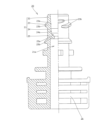
- FIG. 2 is an explanatory diagram showing a spout according to one embodiment of the present invention.
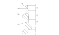
- FIG. 4 is an explanatory diagram illustrating the state of the inner circumferential surface of the spout cylindrical portion.
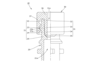
- FIG. 13 is an explanatory diagram showing the state in which the connector is connected to the spout.
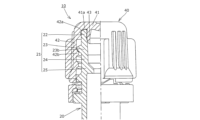
- FIG. 4 is an explanatory diagram showing the state in which the cap is attached to the spout.
- the dispensing unit 10 includes a spout 20 that is attached to the spout of a container (not shown) such as a pouch filled with a liquid content including a nutritional agent for enteral nutrition, a connector 30 that is configured to be connectable to the spout 20, and a cap 40 that can be attached to the spout 20.
- a container not shown
- a connector 30 that is configured to be connectable to the spout 20
- a cap 40 that can be attached to the spout 20.
- the spout 20 is formed as an injection molded product made of synthetic resin or the like, and as shown in FIG. 1, is integrally provided with a cylindrical spout tubular portion 21 having an internal pouring flow path 21a that extends vertically for pouring out the liquid content, and a container attachment portion 26 that is attached to the container by thermal welding, and as shown in FIG. 3, is connected to the connector 30 with a connector pouring tubular portion 31 inserted into the spout tubular portion 21.
- the spout tubular portion 21 is formed to protrude upward from the container mounting portion 26, and as shown in FIG. 1, has an upper end region 22 formed on its upper end side, an upper threaded region 23 adjacent to the lower side of the upper end region 22 and having a spout threaded portion 23b protruding from its outer circumferential surface, a spout lower region 24 formed adjacent to the lower side of the upper threaded region 23 and having a sealing tapered inner circumferential surface 24a that can be in close contact with the outer circumferential surface of the connector injection tube portion 31 when connected to the connector 30, and a protruding portion region 25 formed adjacent to the lower side of the spout lower region 24.
- the inner surface 22a of the upper end region 22 is formed so that its entire area is located outer than a virtual tapered surface T formed by extending the sealing tapered inner surface 24a upward (i.e., by extending the upper end portion of the sealing tapered inner surface 24a upward).
- a virtual tapered surface T formed by extending the sealing tapered inner surface 24a upward (i.e., by extending the upper end portion of the sealing tapered inner surface 24a upward).
- the inclination angles of the inner circumferential surfaces of the upper end region 22 and the upper threaded region 23 are exaggerated (the inclination angle in the vertical direction is larger than in other figures).
- the inner peripheral surface 22a of the upper end region 22 is tapered over its entire area so that the diameter increases in the upward direction as shown in Figures 1 and 2, but the specific form of the inner peripheral surface 22a of the upper end region 22 is not limited to a tapered shape, and for example, at least a portion of the vertical region may have a tubular (cylindrical) portion that is parallel to the vertical direction.
- the upper threaded region 23 has an upper tapered inner surface 23a that is tapered so that the diameter increases toward the top, and in this embodiment, the entire inner surface of the upper threaded region 23 is composed of the upper tapered inner surface 23a.
- the inclination angle of the upper tapered inner surface 23a in the vertical direction is greater than the inclination angle of the upper end portion of the sealing tapered inner surface 24a in the vertical direction (at any position in the vertical direction of the upper tapered inner surface 23a).
- the inner surface of the upper threaded region 23 thus formed is located, throughout its entirety, on the outer periphery of a virtual tapered surface T formed by extending the sealing tapered inner surface 24a upward (i.e., by extending the upper end portion of the sealing tapered inner surface 24a upward).
- the inner surface of the upper threaded region 23 is composed of an upper tapered inner surface 23a over its entire area, in other words, it is formed in a tapered shape that increases in diameter toward the upward side over its entire area.
- the specific form of the inner surface of the upper threaded region 23 is not limited to this, and for example, it may have a tubular (cylindrical) portion that is parallel to the vertical direction in at least a portion of its vertical area.
- the upper tapered inner surface 23a is formed only from tapered sections that have the same inclination angle with respect to the vertical direction throughout its entire area (the inclination angle does not change), but the specific form of the upper tapered inner surface 23a is not limited to one formed with the same inclination angle, and may be any type, such as one composed of multiple tapered sections with different inclination angles, or one in which the inclination angle changes depending on the vertical position.
- the spout lower region 24 is tapered so that its diameter increases toward the top, and has a sealing tapered inner surface 24a that can be in close contact with the outer surface of the connector injection tube portion 31 (the sealing tapered outer surface 34a of the connector lower region 34) when connected to the connector 30.
- the sealing tapered inner surface 24a is formed so that its upper end position coincides with the upper end position of the spout lower region 24 (i.e., the lower end position of the upper threaded region 23), and more specifically, the entire area of the spout lower region 24 is composed of the sealing tapered inner surface 24a.
- the inner surface of the spout lower region 24 is composed of a sealing tapered inner surface 24a over its entire area, but the specific form of the inner surface of the spout lower region 24 is not limited to this, and some areas in the vertical direction may have a portion that does not function as a sealing tapered inner surface 24a.
- the inner surface of the spout lower region 24 is formed in a tapered shape that increases in diameter as it approaches the upward direction over its entire area, but the specific form of the inner surface of the spout lower region 24 is not limited to this, and for example, a portion of the inner surface in the vertical direction may have a tubular (cylindrical) portion that is parallel to the vertical direction.
- the specific form of the sealing tapered inner surface 24a may be any form, such as one that is composed only of tapered sections having the same inclination angle in the vertical direction (the inclination angle does not change), one that is composed of multiple tapered sections having different inclination angles, or one in which the inclination angle changes depending on the vertical position.
- the protruding region 25 is a region having an annular protruding portion 25b formed to protrude toward the inner periphery, and has a third tapered inner periphery surface 25a.
- this third tapered inner surface 25a is adjacent to the lower side of the inner surface of the spout lower region 24 (in this embodiment, the sealing tapered inner surface 24a), and is formed in a tapered shape so that its diameter increases toward the top.
- the inclination angle of the third tapered inner surface 25a in the vertical direction is greater than the inclination angle of the upper end portion of the sealing tapered inner surface 24a in the vertical direction (at any position in the vertical direction of the third tapered inner surface 25a).
- the specific form of the third tapered inner surface 25a may be any, such as one that is composed of only tapered sections with the same inclination angle in the vertical direction (the inclination angle does not change), one that is composed of multiple tapered sections with different inclination angles, or one that changes the inclination angle depending on the vertical position.
- each of the sections 22 to 25 of the spout cylindrical section 21 is formed so that the cross-sectional shape when cut along a plane perpendicular to the up-down direction is circular throughout its entire area.
- the connector 30 is made of a synthetic resin or the like, and is connected to one end of a catheter whose other end is inserted into the patient's body. As shown in Figure 3, the connector 30 is integrally provided with a cylindrical connector injection tube portion 31 which is inserted into the spout tubular portion 21 with the connector 30 connected to the spout 20, a top plate portion 36 having a through hole in its center which communicates with the injection flow path 31a of the connector injection tube portion 31, and a cylindrical skirt portion 37 which hangs down downward from the outer periphery of the top plate portion 36.
- the upper end surface of the spout cylindrical portion 21 may contact the lower surface of the top plate portion 36, or the upper end surface of the spout cylindrical portion 21 may not contact the lower surface of the top plate portion 36.
- the connector injection/dispensing tube portion 31 has a top plate side region 32 that is inserted into the inner circumference of the upper end side region 22, a connector upper side region 33 that is inserted into the inner circumference of the upper threaded region 23, a connector lower side region 34 that is inserted into the inner circumference of the spout lower side region 24, and a connector lower end side region 35 that is inserted into the inner circumference of the protrusion region 25.
- the outer circumferential surfaces of the top plate side region 32, the connector upper side region 33, the connector lower side region 34, and the connector lower end side region 35 are formed in a tapered shape that increases in diameter toward the upward direction over their entire areas.
- the specific form of the outer peripheral surface of each of the parts 32 to 35 of the connector injection/discharge tube portion 31 is not limited to this, and for example, at least a portion of the vertical area may have a tubular (cylindrical) portion parallel to the vertical direction.
- the specific form of the outer peripheral surface of each part 32 to 35 of the connector injection tube portion 31 may be any form, such as one that is composed only of tapered parts having the same inclination angle in the vertical direction (the inclination angle does not change), one that is composed of multiple tapered parts with different inclination angles, or one that changes the inclination angle depending on the vertical position.
- the inner circumferential surface of each of the portions 32 to 35 of the connector injection/injection tube portion 31 is formed so that the cross section thereof when cut along a plane perpendicular to the up-down direction has a circular shape over the entire area.
- the skirt portion 37 has a connector threaded portion 37a on its inner circumference that can be screwed into the spout threaded portion 23b when the connector 30 is connected to the spout 20.
- the outer diameter of the sealing taper outer peripheral surface 34a of the connector lower region 34 is designed to be larger than the inner diameter of the sealing taper inner peripheral surface 24a (at the corresponding location during insertion) of the spout lower region 24, and as shown in FIG. 3, when the connector 30 is connected to the spout 20, the sealing taper outer peripheral surface 34a is inserted into the inner peripheral side of the sealing taper inner peripheral surface 24a so that a first tightening gap is created between the sealing taper inner peripheral surface 24a, thereby forming a seal between the inner peripheral surface of the spout tubular portion 21 and the outer peripheral surface of the connector injection/discharge tubular portion 31.
- the connector upper region 33 is formed so that (at any position in the vertical direction of the connector upper region 33) a tightening margin smaller than the first tightening margin is generated between the connector upper region 33 and the upper threaded region 23 (i.e., the tightening margin at the largest tightening margin between the upper threaded region 23 and the connector upper region 33 is smaller than the tightening margin at the smallest tightening margin of the first tightening margin described above), or so that the connector upper region 33 contacts the inner surface 23a of the upper threaded region 23 without generating a tightening margin between the connector upper region 33 and the upper threaded region 23, or so that the connector upper region 33 is inserted into the upper threaded region 23 so that a gap is generated between the connector upper region 33 and the upper threaded region 23.
- the top plate side region 32 is formed so that (at any position in the vertical direction of the top plate side region 32) there is a tightening margin between it and the upper end side region 22 that is smaller than the first tightening margin (i.e., the tightening margin at the largest tightening margin between the upper end side region 22 and the top plate side region 32 is smaller than the tightening margin at the smallest tightening margin of the first tightening margin described above), or so that it contacts the inner surface of the upper end side region 22 without generating a tightening margin between it and the upper end side region 22, or so that it is inserted into the upper end side region 22 so that a gap is created between it and the upper end side region 22.
- the first tightening margin i.e., the tightening margin at the largest tightening margin between the upper end side region 22 and the top plate side region 32 is smaller than the tightening margin at the smallest tightening margin of the first tightening margin described above
- the connector lower end region 35 is formed to be inserted into the protruding region 25 so that a gap is created between the connector lower end region 35 and the protruding region 25 over its entire area.
- FIG. 3 shows the gap between the protruding region 25 and the connector lower end region 35 as being small, the gap may be larger, and the protruding region 25 and the connector lower end region 35 may be in contact with each other.
- the cap 40 is made of synthetic resin or the like and is attached to the spout 20 when it is not connected to the connector 30. As shown in FIG. 5, the cap 40 is integrally made up of a top plate portion 41, an annular skirt portion 42 that hangs down from the outer periphery of the top plate portion 41, and an annular inner ring portion 43 that protrudes down from the underside of the top plate portion 41 on the inner periphery of the skirt portion 42.
- the top plate portion 41 has an annular contact ring portion 41a formed on the outer periphery of the inner ring portion 43 and protruding downward from the underside of the top plate portion 41.
- the skirt portion 42 is a portion that is positioned on the outer periphery of the spout cylindrical portion 21, and as shown in FIG. 5, on its inner periphery has an outer ring portion 42a and a cap thread portion 42b that screws into the spout thread portion 23b when the cap 40 is attached to the spout 20.
- the cap 40 when the cap 40 is attached to the spout 20, it has a contact ring portion 41a that contacts the upper end surface of the upper end region 22, an outer ring portion 42a that contacts the outer peripheral surface of the upper end region 22, and an inner ring portion 43 that contacts the inner peripheral surface 22a of the upper end region 22, so that the cap 40 seals the spout 20 and prevents the contents of the container (not shown) to which the spout 20 is attached from leaking out.
- the inner surface of the upper threaded region 23 is located throughout its entire area outer than the virtual tapered surface T which is an upward extension of the sealing taper inner surface 24a. This prevents the engagement (insertion) between the sealing taper outer circumferential surface 34a and the sealing taper inner circumferential surface 24a from being hindered due to contact between the inner surface of the upper threaded region 23, which is prone to forming sink marks (dents), and the outer circumferential surface of the connector dispensing tube portion 31 (the connector upper region 33).
- sink marks may occur on the inner surface of the upper threaded region 23, which has the spout threaded portion 23b protruding from its outer peripheral surface, due to shrinkage of the resin material during injection molding of the spout 20. If such sink marks are formed on the inner surface of the upper threaded region 23, there is a problem that the seal between the spout tubular portion 21 and the connector pouring tubular portion 31 is impaired due to the sink marks.
- the inner surface of the upper threaded region 23 is positioned throughout its entire area outer than a virtual tapered surface T formed by extending the sealing taper inner surface 24a upward, and the tightening margin between the inner surface of the upper threaded region 23 and the outer surface of the connector dispensing tube portion 31 is reduced or contact is avoided, thereby improving the insertability of the connector dispensing tube portion 31 into the spout tubular portion 21.
- This allows the sealing taper outer surface 34a and the sealing taper inner surface 24a to be securely fitted together, improving the seal between the inner surface of the spout tubular portion 21 and the outer surface of the connector dispensing tube portion 31.
- sealing tapered inner surface 24a so that its upper end position coincides with the upper end position of the spout lower region 24 (i.e., the lower end position of the upper threaded region 23), it is possible to ensure a wide vertical width of the sealing tapered inner surface 24a, thereby improving the seal between the inner surface of the spout tubular portion 21 and the outer surface of the connector injection/injection tubular portion 31.
- the inner peripheral surface 22a of the upper end region 22 is used as the portion of the inner peripheral surface of the spout cylindrical portion 21 that ensures a tight seal with the cap 40 when connected to the cap 40
- the sealing tapered inner peripheral surface 24a is used (at least mainly) as the portion of the inner peripheral surface of the spout cylindrical portion 21 that ensures a tight seal with the connector 30 when connected to the connector 30.
- the dispensing unit 10 and the connector 30 are described as being used for enteral nutrition, but there is no problem in using the dispensing unit 10 and the connector 30 for purposes other than enteral nutrition.
- the cap 40 is attached to the spout 20 and has a contact ring portion 41a that contacts the upper end surface of the upper end region 22, an outer ring portion 42a that contacts the outer peripheral surface of the upper end region 22, and an inner ring portion 43 that contacts the inner peripheral surface 22a of the upper end region 22, thereby sealing the spout 20,
- the form of the cap 40 is not limited to this.
Landscapes
- Engineering & Computer Science (AREA)
- Mechanical Engineering (AREA)
- Health & Medical Sciences (AREA)
- Life Sciences & Earth Sciences (AREA)
- Animal Behavior & Ethology (AREA)
- General Health & Medical Sciences (AREA)
- Public Health (AREA)
- Veterinary Medicine (AREA)
- Closures For Containers (AREA)
- Medical Preparation Storing Or Oral Administration Devices (AREA)
Abstract
【課題】スパウト筒状部の内周面とコネクタ注出筒部の外周面との間の密封性を向上するスパウトおよび注出ユニットを提供すること。 【解決手段】スパウト筒状部21内にコネクタ注出筒部31が挿入された状態でコネクタ30に接続されるスパウト20であって、スパウト筒状部21は、その外周面にスパウトネジ部23bが形成された上方側ネジ付き領域23と、上方側ネジ付き領域23の下方側に隣接して形成されたスパウト下方側領域24とを有し、スパウト下方側領域24は、上方に向かうに従って拡径するように形成された、コネクタ注出筒部31の外周面と密着可能な密封用テーパ内周面24aを有し、上方側ネジ付き領域23の内周面は、その全域が、密封用テーパ内周面24aを上方側に延長させた仮想テーパ面Tよりも外周側に位置しているスパウト20。
Description
本発明は、スパウトおよび注出ユニットに関する。
従来から、経腸栄養においては、患者に投与される栄養剤を含む内容液をパウチ等の容器(バッグ)に充填したRTH(Ready To Hang)製剤が広く用いられている。このようなRTH製剤では、内容液を充填した容器の注出口にスパウトを取り付け、内容液を患者に投与する直前にスパウトを開封し、この開封されたスパウトに対して、その一端が患者の体内に挿入されるカテーテルの他端側に接続されたコネクタを接続することで、患者に対して栄養剤を含む内容液を投与することが行われている。
このようなスパウトおよびコネクタでは、近年、栄養系の医療機器に関する国際規格ISO80369-3の関係で、スパウトに形成されたスパウト筒状部(メスコネクタ部)内に、コネクタに形成されたコネクタ注出筒部(オスコネクタ部)を挿入するという、コネクタ接続形態が採用され始めている(例えば特許文献1を参照)。
ところが、本出願人がこのようなスパウトおよびコネクタを含む注出ユニットについて開発を進めていく中で、スパウト筒状部の内周面とコネクタ注出筒部の外周面との間の密封性について改善の余地があることが分かった。
そこで、本発明は、これらの問題点を解決するものであり、簡素な構成で、スパウト筒状部の内周面とコネクタ注出筒部の外周面との間の密封性を向上するスパウトおよび注出ユニットを提供することを目的とするものである。
本発明のスパウトは、スパウト筒状部内にコネクタ注出筒部が挿入された状態でコネクタに接続されるスパウトであって、前記スパウト筒状部は、その外周面にスパウトネジ部が形成された上方側ネジ付き領域と、前記上方側ネジ付き領域の下方側に隣接して形成されたスパウト下方側領域とを有し、前記スパウト下方側領域は、上方に向かうに従って拡径するように形成された、前記コネクタ注出筒部の外周面と密着可能な密封用テーパ内周面を有し、前記上方側ネジ付き領域の内周面は、その全域が、前記密封用テーパ内周面を上方側に延長させた仮想テーパ面よりも外周側に位置していることにより、前記課題を解決するものである。
本発明の注出ユニットの一態様は、前記スパウトと、前記コネクタとを備えることにより、前記課題を解決するものである。
本発明の注出ユニットの他の態様は、スパウトとコネクタとを備え、スパウト筒状部内にコネクタ注出筒部が挿入された状態で前記スパウトに対して前記コネクタが接続される注出ユニットであって、前記スパウト筒状部は、その外周面にスパウトネジ部が形成された上方側ネジ付き領域と、前記上方側ネジ付き領域の下方側に隣接して形成されたスパウト下方側領域とを有し、前記スパウト下方側領域は、上方に向かうに従って拡径するように形成された、前記コネクタ注出筒部の外周面と密着可能な密封用テーパ内周面を有し、前記コネクタ注出筒部は、前記スパウトに対して前記コネクタを接続した状態で、前記上方側ネジ付き領域の内周側に配置されるコネクタ上方側領域と、前記スパウト下方側領域の内周側に配置されるコネクタ下方側領域とを有し、前記コネクタ下方側領域は、前記スパウトに対して前記コネクタを接続した状態で、前記密封用テーパ内周面との間に第1締め代が生じるように、前記密封用テーパ内周面の内周側に挿入される密封用テーパ外周面を有し、前記コネクタ上方側領域は、前記スパウトに対して前記コネクタを接続した状態で、前記上方側ネジ付き領域との間に前記第1締め代よりも小さい締め代が生じる、または、前記上方側ネジ付き領域との間に締め代を生じることなく前記上方側ネジ付き領域との内周面に接触するように、または、前記上方側ネジ付き領域との間に間隔が生じるように、前記上方側ネジ付き領域内に挿入されることにより、前記課題を解決するものである。
上記のいずれかのスパウトまたは注出ユニットでは、前記密封用テーパ内周面は、その上端位置が前記スパウト下方側領域の上端位置に一致するように形成されていてもよい。
上記のいずれかのスパウトまたは注出ユニットでは、前記上方側ネジ付き領域は、上方に向かうに従って拡径するように形成された上方側テーパ内周面を有し、前記上方側テーパ内周面の上下方向に対する傾斜角度は、前記密封用テーパ内周面の上端部分の上下方向に対する傾斜角度よりも大きくてもよい。
上記のいずれかのスパウトまたは注出ユニットでは、前記上方側ネジ付き領域および前記スパウト下方側領域の内周面は、その全域に亘って、上方側に向かうに従って拡径するテーパ状に形成されていてもよい。
上記のいずれかのスパウトまたは注出ユニットでは、前記スパウト筒状部は、前記スパウト下方側領域の内周面の下方側に隣接して形成された第3テーパ内周面を有し、前記第3テーパ内周面は、上方に向かうに従って拡径するように形成され、前記第3テーパ内周面の上下方向に対する傾斜角度は、前記密封用テーパ内周面の上端部分の上下方向に対する傾斜角度よりも大きくてもよい。
上記のいずれかのスパウトまたは注出ユニットでは、前記コネクタ注出筒部は、前記スパウトに対して前記コネクタを接続した状態で、前記上方側ネジ付き領域の内周側に挿入されるコネクタ上方側領域と、前記スパウト下方側領域の内周側に挿入されるコネクタ下方側領域とを有し、前記コネクタ下方側領域は、前記スパウトに対して前記コネクタを接続した状態で、前記密封用テーパ内周面との間に第1締め代が生じるように、前記密封用テーパ内周面の内周側に挿入される密封用テーパ外周面を有し、前記コネクタ上方側領域は、前記スパウトに対して前記コネクタを接続した状態で、前記上方側ネジ付き領域との間に前記第1締め代よりも小さい締め代が生じるように、または、前記上方側ネジ付き領域との間に締め代を生じることなく前記上方側ネジ付き領域の内周面に接触するように、または、前記上方側ネジ付き領域との間に間隔が生じるように、前記上方側ネジ付き領域内に挿入されてもよい。
上記のいずれかのスパウトまたは注出ユニットでは、前記コネクタ下方側領域の外周面は、その全域に亘って、上方側に向かうに従って拡径するテーパ状に形成されていてもよい。
上記のいずれかのスパウトまたは注出ユニットでは、前記コネクタは、前記スパウトネジ部に螺合可能なコネクタネジ部を有していてもよい。
上記のいずれかの注出ユニットでは、前記注出ユニットは、前記スパウトに装着可能なキャップを更に備え、前記スパウト筒状部は、前記上方側ネジ付き領域よりも上方側の上端側領域を有し、前記キャップは、前記スパウトに対して装着された状態で、前記上端側領域の外周面に接触するアウターリング部と、前記上端側領域の内周面に接触するインナーリング部と、前記上端側領域の上端面に接触するコンタクトリング部とを有していてもよい。
本発明の注出ユニットの一態様は、前記スパウトと、前記コネクタとを備えることにより、前記課題を解決するものである。
本発明の注出ユニットの他の態様は、スパウトとコネクタとを備え、スパウト筒状部内にコネクタ注出筒部が挿入された状態で前記スパウトに対して前記コネクタが接続される注出ユニットであって、前記スパウト筒状部は、その外周面にスパウトネジ部が形成された上方側ネジ付き領域と、前記上方側ネジ付き領域の下方側に隣接して形成されたスパウト下方側領域とを有し、前記スパウト下方側領域は、上方に向かうに従って拡径するように形成された、前記コネクタ注出筒部の外周面と密着可能な密封用テーパ内周面を有し、前記コネクタ注出筒部は、前記スパウトに対して前記コネクタを接続した状態で、前記上方側ネジ付き領域の内周側に配置されるコネクタ上方側領域と、前記スパウト下方側領域の内周側に配置されるコネクタ下方側領域とを有し、前記コネクタ下方側領域は、前記スパウトに対して前記コネクタを接続した状態で、前記密封用テーパ内周面との間に第1締め代が生じるように、前記密封用テーパ内周面の内周側に挿入される密封用テーパ外周面を有し、前記コネクタ上方側領域は、前記スパウトに対して前記コネクタを接続した状態で、前記上方側ネジ付き領域との間に前記第1締め代よりも小さい締め代が生じる、または、前記上方側ネジ付き領域との間に締め代を生じることなく前記上方側ネジ付き領域との内周面に接触するように、または、前記上方側ネジ付き領域との間に間隔が生じるように、前記上方側ネジ付き領域内に挿入されることにより、前記課題を解決するものである。
上記のいずれかのスパウトまたは注出ユニットでは、前記密封用テーパ内周面は、その上端位置が前記スパウト下方側領域の上端位置に一致するように形成されていてもよい。
上記のいずれかのスパウトまたは注出ユニットでは、前記上方側ネジ付き領域は、上方に向かうに従って拡径するように形成された上方側テーパ内周面を有し、前記上方側テーパ内周面の上下方向に対する傾斜角度は、前記密封用テーパ内周面の上端部分の上下方向に対する傾斜角度よりも大きくてもよい。
上記のいずれかのスパウトまたは注出ユニットでは、前記上方側ネジ付き領域および前記スパウト下方側領域の内周面は、その全域に亘って、上方側に向かうに従って拡径するテーパ状に形成されていてもよい。
上記のいずれかのスパウトまたは注出ユニットでは、前記スパウト筒状部は、前記スパウト下方側領域の内周面の下方側に隣接して形成された第3テーパ内周面を有し、前記第3テーパ内周面は、上方に向かうに従って拡径するように形成され、前記第3テーパ内周面の上下方向に対する傾斜角度は、前記密封用テーパ内周面の上端部分の上下方向に対する傾斜角度よりも大きくてもよい。
上記のいずれかのスパウトまたは注出ユニットでは、前記コネクタ注出筒部は、前記スパウトに対して前記コネクタを接続した状態で、前記上方側ネジ付き領域の内周側に挿入されるコネクタ上方側領域と、前記スパウト下方側領域の内周側に挿入されるコネクタ下方側領域とを有し、前記コネクタ下方側領域は、前記スパウトに対して前記コネクタを接続した状態で、前記密封用テーパ内周面との間に第1締め代が生じるように、前記密封用テーパ内周面の内周側に挿入される密封用テーパ外周面を有し、前記コネクタ上方側領域は、前記スパウトに対して前記コネクタを接続した状態で、前記上方側ネジ付き領域との間に前記第1締め代よりも小さい締め代が生じるように、または、前記上方側ネジ付き領域との間に締め代を生じることなく前記上方側ネジ付き領域の内周面に接触するように、または、前記上方側ネジ付き領域との間に間隔が生じるように、前記上方側ネジ付き領域内に挿入されてもよい。
上記のいずれかのスパウトまたは注出ユニットでは、前記コネクタ下方側領域の外周面は、その全域に亘って、上方側に向かうに従って拡径するテーパ状に形成されていてもよい。
上記のいずれかのスパウトまたは注出ユニットでは、前記コネクタは、前記スパウトネジ部に螺合可能なコネクタネジ部を有していてもよい。
上記のいずれかの注出ユニットでは、前記注出ユニットは、前記スパウトに装着可能なキャップを更に備え、前記スパウト筒状部は、前記上方側ネジ付き領域よりも上方側の上端側領域を有し、前記キャップは、前記スパウトに対して装着された状態で、前記上端側領域の外周面に接触するアウターリング部と、前記上端側領域の内周面に接触するインナーリング部と、前記上端側領域の上端面に接触するコンタクトリング部とを有していてもよい。
本発明によれば、簡素な構成で、スパウト筒状部の内周面とコネクタ注出筒部の外周面との間の密封性を向上することができる。
以下に、本発明の一実施形態に係る注出ユニット10について、図面に基づいて説明する。
まず、注出ユニット10は、図1~図5に示すように、経腸栄養用の栄養剤を含む内容液が充填されたパウチ等の容器(図示しない)の注出口に装着されるスパウト20と、スパウト20に接続可能に構成されたコネクタ30と、スパウト20に装着可能なキャップ40とを備えている。
以下、各構成要素の具体的構成について、図面に基づいて説明する。
まず、スパウト20は、合成樹脂等から成る射出成形品として形成され、図1に示すように、内容液を注出するための上下方向に沿って延びる注出流路21aを内側に有した筒状のスパウト筒状部21と、熱溶着によって容器に装着される容器用取付部26とを一体に備え、図3に示すように、そのスパウト筒状部21内にコネクタ注出筒部31が挿入された状態でコネクタ30に接続されるものである。
スパウト筒状部21は、容器用取付部26から上方側に向けて突出して形成され、図1に示すように、その上端側に形成された上端側領域22と、上端側領域22の下方側に隣接し、その外周面にスパウトネジ部23bが突出して形成された上方側ネジ付き領域23と、上方側ネジ付き領域23の下方側に隣接して形成された領域であって、コネクタ30との接続時にコネクタ注出筒部31の外周面と密着可能な密封用テーパ内周面24aを有したスパウト下方側領域24と、スパウト下方側領域24の下方側に隣接して形成された突出部付き領域25とを有している。
以下に、スパウト筒状部21の各部22~25の内周面の態様について説明する。
まず、上端側領域22の内周面22aは、図2に示すように、その全域が、密封用テーパ内周面24aを上方側に延長させた(すなわち、密封用テーパ内周面24aの上端側部分を上方側に延長させた)仮想テーパ面Tよりも外周側に位置するように形成されている。
ここで、図2においては、発明の理解を容易にするために、上端側領域22および上方側ネジ付き領域23の内周面の傾斜角度を誇張して(他の図よりも上下方向に対する傾斜角度を大きく)描いている。
ここで、図2においては、発明の理解を容易にするために、上端側領域22および上方側ネジ付き領域23の内周面の傾斜角度を誇張して(他の図よりも上下方向に対する傾斜角度を大きく)描いている。
なお、本実施形態では、上端側領域22の内周面22aは、図1や図2に示すように、その全域に亘って、上方に向かうに従って拡径するようにテーパ状に形成されているが、上端側領域22の内周面22aの具体的態様は、テーパ状のものに限定されず、例えば、その上下方向の少なくとも一部領域に、上下方向に平行な筒状(円筒状)の部分を有していてもよい。
また、上方側ネジ付き領域23は、図1や図2に示すように、上方に向かうに従って拡径するようにテーパ状に形成された上方側テーパ内周面23aを有しており、本実施形態では、上方側ネジ付き領域23の内周面の全域が、上方側テーパ内周面23aから構成されている。
上方側テーパ内周面23aの上下方向に対する傾斜角度は、(上方側テーパ内周面23aの上下方向のいずれの位置においても、)密封用テーパ内周面24aの上端部分の上下方向に対する傾斜角度よりも大きい。
このように形成された上方側ネジ付き領域23の内周面は、図2に示すように、その全域が、密封用テーパ内周面24aを上方側に延長させた(すなわち、密封用テーパ内周面24aの上端側部分を上方側に延長させた)仮想テーパ面Tよりも外周側に位置している。
上方側テーパ内周面23aの上下方向に対する傾斜角度は、(上方側テーパ内周面23aの上下方向のいずれの位置においても、)密封用テーパ内周面24aの上端部分の上下方向に対する傾斜角度よりも大きい。
このように形成された上方側ネジ付き領域23の内周面は、図2に示すように、その全域が、密封用テーパ内周面24aを上方側に延長させた(すなわち、密封用テーパ内周面24aの上端側部分を上方側に延長させた)仮想テーパ面Tよりも外周側に位置している。
なお、本実施形態では、上方側ネジ付き領域23の内周面が、その全域に亘って上方側テーパ内周面23aから構成され、言い換えると、その全域に亘って上方側に向かうに従って拡径するテーパ状に形成されているが、上方側ネジ付き領域23の内周面の具体的態様はこれに限定されず、例えば、その上下方向の少なくとも一部領域に、上下方向に平行な筒状(円筒状)の部分を有していてもよい。
また、本実施形態では、上方側テーパ内周面23aが、その全域に亘って上下方向に対する傾斜角度が同一の(傾斜角度が変わらない)テーパ部のみから形成されているが、上方側テーパ内周面23aの具体的態様は、同一の傾斜角度で形成されたものに限定されず、傾斜角度が異なる複数のテーパ部から構成されるものや、上下方向の位置によって傾斜角度が変化するもの等、如何なるものでもよい。
また、本実施形態では、上方側テーパ内周面23aが、その全域に亘って上下方向に対する傾斜角度が同一の(傾斜角度が変わらない)テーパ部のみから形成されているが、上方側テーパ内周面23aの具体的態様は、同一の傾斜角度で形成されたものに限定されず、傾斜角度が異なる複数のテーパ部から構成されるものや、上下方向の位置によって傾斜角度が変化するもの等、如何なるものでもよい。
また、スパウト下方側領域24は、図1や図2に示すように、上方に向かうに従って拡径するようにテーパ状に形成され、コネクタ30との接続時にコネクタ注出筒部31の外周面(コネクタ下方側領域34の密封用テーパ外周面34a)と密着可能な密封用テーパ内周面24aを有している。
本実施形態では、密封用テーパ内周面24aは、図1や図2に示すように、その上端位置がスパウト下方側領域24の上端位置(すなわち、上方側ネジ付き領域23の下端位置)に一致するように形成され、更に具体的には、スパウト下方側領域24の全域が、密封用テーパ内周面24aから構成されている。
本実施形態では、密封用テーパ内周面24aは、図1や図2に示すように、その上端位置がスパウト下方側領域24の上端位置(すなわち、上方側ネジ付き領域23の下端位置)に一致するように形成され、更に具体的には、スパウト下方側領域24の全域が、密封用テーパ内周面24aから構成されている。
なお、本実施形態では、スパウト下方側領域24の内周面が、その全域に亘って密封用テーパ内周面24aから構成されているが、スパウト下方側領域24の内周面の具体的態様はこれに限定されず、その上下方向の一部領域に、密封用テーパ内周面24aとして機能しない部分を有していてもよい。
また、本実施形態では、スパウト下方側領域24の内周面が、その全域に亘って上方側に向かうに従って拡径するテーパ状に形成されているが、スパウト下方側領域24の内周面の具体的態様はこれに限定されず、例えば、その上下方向の一部領域に、上下方向に平行な筒状(円筒状)の部分を有していてもよい。
また、密封用テーパ内周面24aの具体的態様については、上下方向に対する傾斜角度が同一の(傾斜角度が変わらない)テーパ部のみから構成されるものや、傾斜角度が異なる複数のテーパ部から構成されるものや、上下方向の位置によって傾斜角度が変化するもの等、如何なるものでもよい。
また、本実施形態では、スパウト下方側領域24の内周面が、その全域に亘って上方側に向かうに従って拡径するテーパ状に形成されているが、スパウト下方側領域24の内周面の具体的態様はこれに限定されず、例えば、その上下方向の一部領域に、上下方向に平行な筒状(円筒状)の部分を有していてもよい。
また、密封用テーパ内周面24aの具体的態様については、上下方向に対する傾斜角度が同一の(傾斜角度が変わらない)テーパ部のみから構成されるものや、傾斜角度が異なる複数のテーパ部から構成されるものや、上下方向の位置によって傾斜角度が変化するもの等、如何なるものでもよい。
また、突出部付き領域25は、図1に示すように、内周側に向けて突出して形成された環状突出部25bを有した領域であり、第3テーパ内周面25aを有している。
この第3テーパ内周面25aは、図1に示すように、スパウト下方側領域24の内周面(本実施形態では、密封用テーパ内周面24a)の下方側に隣接して、上方に向かうに従って拡径するようにテーパ状に形成されている。
第3テーパ内周面25aの上下方向に対する傾斜角度は、(第3テーパ内周面25aの上下方向のいずれの位置においても、)密封用テーパ内周面24aの上端部分の上下方向に対する傾斜角度よりも大きい。
この第3テーパ内周面25aは、図1に示すように、スパウト下方側領域24の内周面(本実施形態では、密封用テーパ内周面24a)の下方側に隣接して、上方に向かうに従って拡径するようにテーパ状に形成されている。
第3テーパ内周面25aの上下方向に対する傾斜角度は、(第3テーパ内周面25aの上下方向のいずれの位置においても、)密封用テーパ内周面24aの上端部分の上下方向に対する傾斜角度よりも大きい。
なお、第3テーパ内周面25aの具体的態様については、上下方向に対する傾斜角度が同一の(傾斜角度が変わらない)テーパ部のみから構成されるものや、傾斜角度が異なる複数のテーパ部から構成されるものや、上下方向の位置によって傾斜角度が変化するもの等、如何なるものでもよい。
また、スパウト筒状部21の各部22~25の内周面は、その全域に亘って、上下方向に垂直な平面で切った場合の断面形状が、円形状に形成されている。
コネクタ30は、合成樹脂等から形成され、患者の体内にその一端が挿入されるカテーテルの他端側に接続されるものであり、図3に示すように、スパウト20に対してコネクタ30を接続した状態でスパウト筒状部21内に挿入される筒状のコネクタ注出筒部31と、その中央にコネクタ注出筒部31の注出流路31aに連通する貫通孔を有した天板部36と、天板部36の外周縁から下方側に向けて垂下する筒状のスカート部37とを一体に備えている。
なお、スパウト20に対してコネクタ30を接続した状態では、図3に示すように、スパウト筒状部21の上端面が天板部36の下面に接触してもよく、スパウト筒状部21の上端面が天板部36の下面に接触しないようにしてもよい。
なお、スパウト20に対してコネクタ30を接続した状態では、図3に示すように、スパウト筒状部21の上端面が天板部36の下面に接触してもよく、スパウト筒状部21の上端面が天板部36の下面に接触しないようにしてもよい。
コネクタ注出筒部31は、図3に示すように、スパウト20に対してコネクタ30を接続した状態で、上端側領域22の内周側に挿入される天板側領域32と、上方側ネジ付き領域23の内周側に挿入されるコネクタ上方側領域33と、スパウト下方側領域24の内周側に挿入されるコネクタ下方側領域34と、突出部付き領域25の内周側に挿入されるコネクタ下端側領域35とを有している。
本実施形態では、天板側領域32、コネクタ上方側領域33、コネクタ下方側領域34、およびコネクタ下端側領域35の外周面は、その全域に亘って、上方側に向かうに従って拡径するテーパ状に形成されている。
しかしながら、これらコネクタ注出筒部31の各部32~35の外周面の具体的態様はこれに限定されず、例えば、その上下方向の少なくとも一部領域に、上下方向に平行な筒状(円筒状)の部分を有していてもよい。
また、コネクタ注出筒部31の各部32~35の外周面を、上方側に向かうに従って拡径するテーパ状に形成する場合、コネクタ注出筒部31の各部32~35の外周面の具体的態様については、上下方向に対する傾斜角度が同一の(傾斜角度が変わらない)テーパ部のみから構成されるものや、傾斜角度が異なる複数のテーパ部から構成されるものや、上下方向の位置によって傾斜角度が変化するもの等、如何なるものでもよい。
また、コネクタ注出筒部31の各部32~35の内周面は、その全域に亘って、上下方向に垂直な平面で切った場合の断面形状が、円形状に形成されている。
しかしながら、これらコネクタ注出筒部31の各部32~35の外周面の具体的態様はこれに限定されず、例えば、その上下方向の少なくとも一部領域に、上下方向に平行な筒状(円筒状)の部分を有していてもよい。
また、コネクタ注出筒部31の各部32~35の外周面を、上方側に向かうに従って拡径するテーパ状に形成する場合、コネクタ注出筒部31の各部32~35の外周面の具体的態様については、上下方向に対する傾斜角度が同一の(傾斜角度が変わらない)テーパ部のみから構成されるものや、傾斜角度が異なる複数のテーパ部から構成されるものや、上下方向の位置によって傾斜角度が変化するもの等、如何なるものでもよい。
また、コネクタ注出筒部31の各部32~35の内周面は、その全域に亘って、上下方向に垂直な平面で切った場合の断面形状が、円形状に形成されている。
また、スカート部37は、図1や図3に示すように、コネクタ30がスパウト20に対して接続された状態でスパウトネジ部23bに螺合可能なコネクタネジ部37aをその内周側に有している。
次に、スパウト20に対してコネクタ30を接続した状態における、スパウト筒状部21の内周面およびコネクタ注出筒部31の外周面の関係について、以下に説明する。
まず、コネクタ下方側領域34の密封用テーパ外周面34aの外径は、スパウト下方側領域24の密封用テーパ内周面24a(の挿入時における対応箇所)の内径よりも大きく設計されており、図3に示すように、スパウト20に対してコネクタ30を接続した状態では、密封用テーパ外周面34aが、密封用テーパ内周面24aとの間に第1締め代が生じるように、密封用テーパ内周面24aの内周側に挿入され、これにより、スパウト筒状部21の内周面とコネクタ注出筒部31の外周面との間が密封される。
また、図3に示すように、スパウト20に対してコネクタ30を接続した状態では、コネクタ上方側領域33は、(コネクタ上方側領域33の上下方向のいずれの位置においても、)上方側ネジ付き領域23との間に第1締め代よりも小さい締め代が生じるように(すなわち、上方側ネジ付き領域23とコネクタ上方側領域33との間の締め代のうち締め代が最も大きい部分の締め代が、上述した第1締め代のうち締め代が最も小さい部分の締め代よりも小さくなるように)、または、上方側ネジ付き領域23との間に締め代を生じることなく上方側ネジ付き領域23の内周面23aに接触するように、または、上方側ネジ付き領域23との間に間隔が生じるように、上方側ネジ付き領域23内に挿入されるように形成されている。
また、同様に、図3に示すように、スパウト20に対してコネクタ30を接続した状態では、天板側領域32は、(天板側領域32の上下方向のいずれの位置においても、)上端側領域22との間に第1締め代よりも小さい締め代が生じるように(すなわち、上端側領域22と天板側領域32との間の締め代のうち締め代が最も大きい部分の締め代が、上述した第1締め代のうち締め代が最も小さい部分の締め代よりも小さくなるように)、または、上端側領域22との間に締め代を生じることなく上端側領域22の内周面に接触するように、または、上端側領域22との間に間隔が生じるように、上端側領域22内に挿入されるように形成されている。
また、図3に示すように、スパウト20に対してコネクタ30を接続した状態では、コネクタ下端側領域35は、その全域に亘って、突出部付き領域25との間に間隔が生じるように、突出部付き領域25内に挿入されるように形成されている。
なお、図3では、突出部付き領域25とコネクタ下端側領域35との間の間隔が僅かであるように描いたが、当該間隔はもっと大きいものであってもよく、突出部付き領域25とコネクタ下端側領域35が接触していてもよい。
なお、図3では、突出部付き領域25とコネクタ下端側領域35との間の間隔が僅かであるように描いたが、当該間隔はもっと大きいものであってもよく、突出部付き領域25とコネクタ下端側領域35が接触していてもよい。
キャップ40は、合成樹脂等から形成され、コネクタ30に接続されていない状態のスパウト20に装着されるものであり、図5に示すように、天板部41と、天板部41の外周縁から下方側に向けて垂下する環状のスカート部42と、スカート部42の内周側において天板部41の下面から下方側に向けて突出する環状のインナーリング部43とを一体に備えている。
天板部41は、図5に示すように、インナーリング部43の外周側において、天板部41の下面から下方側に向けて突出して形成された環状のコンタクトリング部41aを有している。
スカート部42は、スパウト筒状部21の外周側に配置される部位であり、図5に示すように、アウターリング部42aと、キャップ40がスパウト20に対して装着された状態でスパウトネジ部23bに螺合するキャップネジ部42bとをその内周側に有している。
キャップ40は、図5に示すように、スパウト20に対して装着された状態で、上端側領域22の上端面に接触するコンタクトリング部41aと、上端側領域22の外周面に接触するアウターリング部42aと、上端側領域22の内周面22aに接触するインナーリング部43とを有し、これにより、キャップ40によってスパウト20を密封し、スパウト20が取り付けられた容器(図示しない)内の内容液が漏れ出すことを防止するように構成されている。
このようにして得られた本実施形態の注出ユニット10では、上方側ネジ付き領域23の内周面が、その全域に亘って、密封用テーパ内周面24aを上方側に延長させた仮想テーパ面Tよりも外周側に位置していることにより、ヒケ(凹み)が形成されがちな上方側ネジ付き領域23の内周面とコネクタ注出筒部31(のコネクタ上方側領域33)の外周面との間の接触に起因して、密封用テーパ外周面34aと密封用テーパ内周面24aとの間の嵌合(挿入)が阻害されてしまうことを回避できるため、密封用テーパ外周面34aと密封用テーパ内周面24aとの間の嵌合による、スパウト筒状部21の内周面とコネクタ注出筒部31の外周面との間の密封性を向上させることができる。
すなわち、その外周面にスパウトネジ部23bが突出して形成された上方側ネジ付き領域23の内周面には、スパウト20の射出成形時における樹脂材料の収縮に起因してヒケが生じることがあり、このようなヒケが上方側ネジ付き領域23の内周面に形成された場合、当該ヒケに起因してスパウト筒状部21とコネクタ注出筒部31との間の密封性が損なわれるという問題があった。
そこで、本実施形態の注出ユニット10では、上方側ネジ付き領域23の内周面を、その全域に亘って、密封用テーパ内周面24aを上方側に延長させた仮想テーパ面Tよりも外周側に位置させ、上方側ネジ付き領域23の内周面とコネクタ注出筒部31の外周面との間の締め代を小さくするまたは接触を避けることで、スパウト筒状部21に対するコネクタ注出筒部31の挿入性を向上させ、これにより、密封用テーパ外周面34aと密封用テーパ内周面24aとを確実に嵌合させて、スパウト筒状部21の内周面とコネクタ注出筒部31の外周面との間の密封性を向上させることができる。
すなわち、その外周面にスパウトネジ部23bが突出して形成された上方側ネジ付き領域23の内周面には、スパウト20の射出成形時における樹脂材料の収縮に起因してヒケが生じることがあり、このようなヒケが上方側ネジ付き領域23の内周面に形成された場合、当該ヒケに起因してスパウト筒状部21とコネクタ注出筒部31との間の密封性が損なわれるという問題があった。
そこで、本実施形態の注出ユニット10では、上方側ネジ付き領域23の内周面を、その全域に亘って、密封用テーパ内周面24aを上方側に延長させた仮想テーパ面Tよりも外周側に位置させ、上方側ネジ付き領域23の内周面とコネクタ注出筒部31の外周面との間の締め代を小さくするまたは接触を避けることで、スパウト筒状部21に対するコネクタ注出筒部31の挿入性を向上させ、これにより、密封用テーパ外周面34aと密封用テーパ内周面24aとを確実に嵌合させて、スパウト筒状部21の内周面とコネクタ注出筒部31の外周面との間の密封性を向上させることができる。
また、密封用テーパ内周面24aを、その上端位置がスパウト下方側領域24の上端位置(すなわち、上方側ネジ付き領域23の下端位置)に一致するように形成することにより、密封用テーパ内周面24aの上下方向幅を広く確保することが可能であるため、スパウト筒状部21の内周面とコネクタ注出筒部31の外周面との間の密封性を向上させることができる。
また、本実施形態の注出ユニット10では、スパウト筒状部21の内周面のうち、キャップ40との接続時にキャップ40との間の密封を確保する部位として、上端側領域22の内周面22aを利用し、また、コネクタ30との接続時にコネクタ30との間の密封を確保する部位として、(少なくとも主に)密封用テーパ内周面24aを利用している。
このように、スパウト筒状部21の内周面のうち、キャップ40との間の密封を確保する部位(内周面22a)と、コネクタ30との間の密封を確保する部位(密封用テーパ内周面24a)とを異ならせることにより、相互間で影響を与えることを回避できる。
このように、スパウト筒状部21の内周面のうち、キャップ40との間の密封を確保する部位(内周面22a)と、コネクタ30との間の密封を確保する部位(密封用テーパ内周面24a)とを異ならせることにより、相互間で影響を与えることを回避できる。
以上、本発明の実施形態を詳述したが、本発明は上記実施形態に限定されるものではなく、特許請求の範囲に記載された本発明を逸脱することなく種々の設計変更を行なうことが可能である。
例えば、上述した実施形態では、注出ユニット10およびコネクタ30が経腸栄養の用途で用いられるものとして説明したが、注出ユニット10およびコネクタ30を、経腸栄養以外の用途で用いても何ら構わない。
また、上述した実施形態では、キャップ40がスパウト20に対して装着され、上端側領域22の上端面に接触するコンタクトリング部41aと、上端側領域22の外周面に接触するアウターリング部42aと、上端側領域22の内周面22aに接触するインナーリング部43とを有し、これにより、キャップ40によってスパウト20を密封するものとして説明したが、キャップ40の形態はこれに限らない。さらにキャップ40の代わりにアルミシールによってスパウト筒状部21の開口を塞ぐものや、当該アルミシールとキャップ40とを併用したものなどその他の密封形態を用いても何ら構わない。
10 ・・・ 注出ユニット
20 ・・・ スパウト
21 ・・・ スパウト筒状部
21a ・・・ 注出流路
22 ・・・ 上端側領域
22a ・・・ 内周面
23 ・・・ 上方側ネジ付き領域
23a ・・・ 上方側テーパ内周面
23b ・・・ スパウトネジ部
24 ・・・ スパウト下方側領域
24a ・・・ 密封用テーパ内周面
25 ・・・ 突出部付き領域
25a ・・・ 第3テーパ内周面
25b ・・・ 環状突出部
26 ・・・ 容器用取付部
30 ・・・ コネクタ
31 ・・・ コネクタ注出筒部
31a ・・・ 注出流路
32 ・・・ 天板側領域
33 ・・・ コネクタ上方側領域
34 ・・・ コネクタ下方側領域
34a ・・・ 密封用テーパ外周面
35 ・・・ コネクタ下端側領域
36 ・・・ 天板部
37 ・・・ スカート部
37a ・・・ コネクタネジ部
40 ・・・ キャップ
41 ・・・ 天板部
41a ・・・ コンタクトリング部
42 ・・・ スカート部
42a ・・・ アウターリング部
42b ・・・ キャップネジ部
43 ・・・ インナーリング部
T ・・・ 仮想テーパ面
20 ・・・ スパウト
21 ・・・ スパウト筒状部
21a ・・・ 注出流路
22 ・・・ 上端側領域
22a ・・・ 内周面
23 ・・・ 上方側ネジ付き領域
23a ・・・ 上方側テーパ内周面
23b ・・・ スパウトネジ部
24 ・・・ スパウト下方側領域
24a ・・・ 密封用テーパ内周面
25 ・・・ 突出部付き領域
25a ・・・ 第3テーパ内周面
25b ・・・ 環状突出部
26 ・・・ 容器用取付部
30 ・・・ コネクタ
31 ・・・ コネクタ注出筒部
31a ・・・ 注出流路
32 ・・・ 天板側領域
33 ・・・ コネクタ上方側領域
34 ・・・ コネクタ下方側領域
34a ・・・ 密封用テーパ外周面
35 ・・・ コネクタ下端側領域
36 ・・・ 天板部
37 ・・・ スカート部
37a ・・・ コネクタネジ部
40 ・・・ キャップ
41 ・・・ 天板部
41a ・・・ コンタクトリング部
42 ・・・ スカート部
42a ・・・ アウターリング部
42b ・・・ キャップネジ部
43 ・・・ インナーリング部
T ・・・ 仮想テーパ面
Claims (11)
- スパウト筒状部内にコネクタ注出筒部が挿入された状態でコネクタに接続されるスパウトであって、
前記スパウト筒状部は、その外周面にスパウトネジ部が形成された上方側ネジ付き領域と、前記上方側ネジ付き領域の下方側に隣接して形成されたスパウト下方側領域とを有し、
前記スパウト下方側領域は、上方に向かうに従って拡径するように形成された、前記コネクタ注出筒部の外周面と密着可能な密封用テーパ内周面を有し、
前記上方側ネジ付き領域の内周面は、その全域が、前記密封用テーパ内周面を上方側に延長させた仮想テーパ面よりも外周側に位置していることを特徴とするスパウト。 - 前記密封用テーパ内周面は、その上端位置が前記スパウト下方側領域の上端位置に一致するように形成されていることを特徴とする請求項1に記載のスパウト。
- 前記上方側ネジ付き領域は、上方に向かうに従って拡径するように形成された上方側テーパ内周面を有し、
前記上方側テーパ内周面の上下方向に対する傾斜角度は、前記密封用テーパ内周面の上端部分の上下方向に対する傾斜角度よりも大きいことを特徴とする請求項1に記載のスパウト。 - 前記上方側ネジ付き領域および前記スパウト下方側領域の内周面は、その全域に亘って、上方側に向かうに従って拡径するテーパ状に形成されていることを特徴とする請求項1に記載のスパウト。
- 前記スパウト筒状部は、前記スパウト下方側領域の内周面の下方側に隣接して形成された第3テーパ内周面を有し、
前記第3テーパ内周面は、上方に向かうに従って拡径するように形成され、
前記第3テーパ内周面の上下方向に対する傾斜角度は、前記密封用テーパ内周面の上端部分の上下方向に対する傾斜角度よりも大きいことを特徴とする請求項1に記載のスパウト。 - 請求項1に記載のスパウトと、前記コネクタとを備えることを特徴とする注出ユニット。
- 前記コネクタ注出筒部は、前記スパウトに対して前記コネクタを接続した状態で、前記上方側ネジ付き領域の内周側に挿入されるコネクタ上方側領域と、前記スパウト下方側領域の内周側に挿入されるコネクタ下方側領域とを有し、
前記コネクタ下方側領域は、前記スパウトに対して前記コネクタを接続した状態で、前記密封用テーパ内周面との間に第1締め代が生じるように、前記密封用テーパ内周面の内周側に挿入される密封用テーパ外周面を有し、
前記コネクタ上方側領域は、前記スパウトに対して前記コネクタを接続した状態で、前記上方側ネジ付き領域との間に前記第1締め代よりも小さい締め代が生じるように、または、前記上方側ネジ付き領域との間に締め代を生じることなく前記上方側ネジ付き領域の内周面に接触するように、または、前記上方側ネジ付き領域との間に間隔が生じるように、前記上方側ネジ付き領域内に挿入されることを特徴とする請求項6に記載の注出ユニット。 - 前記コネクタ下方側領域の外周面は、その全域に亘って、上方側に向かうに従って拡径するテーパ状に形成されていることを特徴とする請求項7に記載の注出ユニット。
- 前記コネクタは、前記スパウトネジ部に螺合可能なコネクタネジ部を有していることを特徴とする請求項6に記載の注出ユニット。
- 前記注出ユニットは、前記スパウトに装着可能なキャップを更に備え、
前記スパウト筒状部は、前記上方側ネジ付き領域よりも上方側の上端側領域を有し、
前記キャップは、前記スパウトに対して装着された状態で、前記上端側領域の外周面に接触するアウターリング部と、前記上端側領域の内周面に接触するインナーリング部と、前記上端側領域の上端面に接触するコンタクトリング部とを有することを特徴とする請求項6に記載の注出ユニット。 - スパウトとコネクタとを備え、スパウト筒状部内にコネクタ注出筒部が挿入された状態で前記スパウトに対して前記コネクタが接続される注出ユニットであって、
前記スパウト筒状部は、その外周面にスパウトネジ部が形成された上方側ネジ付き領域と、前記上方側ネジ付き領域の下方側に隣接して形成されたスパウト下方側領域とを有し、
前記スパウト下方側領域は、上方に向かうに従って拡径するように形成された、前記コネクタ注出筒部の外周面と密着可能な密封用テーパ内周面を有し、
前記コネクタ注出筒部は、前記スパウトに対して前記コネクタを接続した状態で、前記上方側ネジ付き領域の内周側に配置されるコネクタ上方側領域と、前記スパウト下方側領域の内周側に配置されるコネクタ下方側領域とを有し、
前記コネクタ下方側領域は、前記スパウトに対して前記コネクタを接続した状態で、前記密封用テーパ内周面との間に第1締め代が生じるように、前記密封用テーパ内周面の内周側に挿入される密封用テーパ外周面を有し、
前記コネクタ上方側領域は、前記スパウトに対して前記コネクタを接続した状態で、前記上方側ネジ付き領域との間に前記第1締め代よりも小さい締め代が生じる、または、前記上方側ネジ付き領域との間に締め代を生じることなく前記上方側ネジ付き領域との内周面に接触するように、または、前記上方側ネジ付き領域との間に間隔が生じるように、前記上方側ネジ付き領域内に挿入されることを特徴とする注出ユニット。
Applications Claiming Priority (2)
| Application Number | Priority Date | Filing Date | Title |
|---|---|---|---|
| JP2023-093712 | 2023-06-07 | ||
| JP2023093712A JP7775256B2 (ja) | 2023-06-07 | 2023-06-07 | スパウトおよび注出ユニット |
Publications (1)
| Publication Number | Publication Date |
|---|---|
| WO2024252902A1 true WO2024252902A1 (ja) | 2024-12-12 |
Family
ID=93795206
Family Applications (1)
| Application Number | Title | Priority Date | Filing Date |
|---|---|---|---|
| PCT/JP2024/018440 Ceased WO2024252902A1 (ja) | 2023-06-07 | 2024-05-20 | スパウトおよび注出ユニット |
Country Status (3)
| Country | Link |
|---|---|
| JP (1) | JP7775256B2 (ja) |
| TW (1) | TW202448760A (ja) |
| WO (1) | WO2024252902A1 (ja) |
Citations (4)
| Publication number | Priority date | Publication date | Assignee | Title |
|---|---|---|---|---|
| JP2001513683A (ja) * | 1997-02-28 | 2001-09-04 | アボツト・ラボラトリーズ | 脆性シール及び流体移動デバイス用コネクタを有する容器クロージャー |
| JP2019081573A (ja) * | 2017-10-30 | 2019-05-30 | 日本クロージャー株式会社 | 注出具 |
| JP2021070533A (ja) * | 2019-10-25 | 2021-05-06 | 株式会社パックプラス | 注出具および包装容器 |
| JP2021138395A (ja) * | 2020-03-03 | 2021-09-16 | 日本クロージャー株式会社 | カバー部材付きスパウト |
Family Cites Families (1)
| Publication number | Priority date | Publication date | Assignee | Title |
|---|---|---|---|---|
| JP2020109026A (ja) | 2020-04-09 | 2020-07-16 | 凸版印刷株式会社 | 口栓構造、口栓付き包装袋 |
-
2023
- 2023-06-07 JP JP2023093712A patent/JP7775256B2/ja active Active
-
2024
- 2024-05-20 WO PCT/JP2024/018440 patent/WO2024252902A1/ja not_active Ceased
- 2024-05-29 TW TW113119826A patent/TW202448760A/zh unknown
Patent Citations (4)
| Publication number | Priority date | Publication date | Assignee | Title |
|---|---|---|---|---|
| JP2001513683A (ja) * | 1997-02-28 | 2001-09-04 | アボツト・ラボラトリーズ | 脆性シール及び流体移動デバイス用コネクタを有する容器クロージャー |
| JP2019081573A (ja) * | 2017-10-30 | 2019-05-30 | 日本クロージャー株式会社 | 注出具 |
| JP2021070533A (ja) * | 2019-10-25 | 2021-05-06 | 株式会社パックプラス | 注出具および包装容器 |
| JP2021138395A (ja) * | 2020-03-03 | 2021-09-16 | 日本クロージャー株式会社 | カバー部材付きスパウト |
Also Published As
| Publication number | Publication date |
|---|---|
| JP2024175746A (ja) | 2024-12-19 |
| TW202448760A (zh) | 2024-12-16 |
| JP7775256B2 (ja) | 2025-11-25 |
Similar Documents
| Publication | Publication Date | Title |
|---|---|---|
| US2848145A (en) | Pouring adapter | |
| US10293988B2 (en) | Fitment and overcap therefor | |
| US2763402A (en) | Adapter | |
| US5772076A (en) | Hot fill dispensing closure | |
| WO2020110468A1 (ja) | 合成樹脂製容器、及び合成樹脂製容器の製造方法 | |
| JP7775256B2 (ja) | スパウトおよび注出ユニット | |
| IT9067170A1 (it) | Dispositivo di chiusura e di erogazione di prodotto liquido da un contenitore. | |
| BRPI0514822B1 (pt) | Seal for closure, closure and process | |
| JP2009248978A (ja) | 注出用中栓 | |
| JP5121144B2 (ja) | パウチ用口栓、口栓付きパウチ、および包装体 | |
| JP4539010B2 (ja) | 低開閉トルクで高密封なキャップを有する容器 | |
| TWI813305B (zh) | 蓋組件及帶蓋容器 | |
| JP7805240B2 (ja) | キャップ体 | |
| JP3567340B2 (ja) | 蛇腹注出口付容器 | |
| JP7195817B2 (ja) | カバー付きスパウト | |
| JP7370290B2 (ja) | 樹脂製キャップ | |
| JP2019167139A (ja) | 樹脂製キャップ及びこの樹脂製キャップと容器口部の組み合わせ | |
| JP7359600B2 (ja) | スリットバルブ及び注出キャップ | |
| JP2025150111A (ja) | 合成樹脂製スパウト | |
| JP4539009B2 (ja) | 口栓 | |
| JP2005212876A (ja) | 合成樹脂製壜体の口筒部 | |
| JP2005104484A (ja) | 封緘リング付口栓 | |
| KR200217946Y1 (ko) | 오일상 액체용 용기 | |
| JP2024158988A (ja) | 注出キャップ | |
| JP3541483B2 (ja) | 液体注出用容器 |
Legal Events
| Date | Code | Title | Description |
|---|---|---|---|
| 121 | Ep: the epo has been informed by wipo that ep was designated in this application |
Ref document number: 24819135 Country of ref document: EP Kind code of ref document: A1 |
|
| NENP | Non-entry into the national phase |
Ref country code: DE |
|
| 122 | Ep: pct application non-entry in european phase |
Ref document number: 24819135 Country of ref document: EP Kind code of ref document: A1 |