WO2024252831A1 - 作業機の油圧システム、作業機、及び作業機の制御方法 - Google Patents
作業機の油圧システム、作業機、及び作業機の制御方法 Download PDFInfo
- Publication number
- WO2024252831A1 WO2024252831A1 PCT/JP2024/016987 JP2024016987W WO2024252831A1 WO 2024252831 A1 WO2024252831 A1 WO 2024252831A1 JP 2024016987 W JP2024016987 W JP 2024016987W WO 2024252831 A1 WO2024252831 A1 WO 2024252831A1
- Authority
- WO
- WIPO (PCT)
- Prior art keywords
- hydraulic
- work machine
- control device
- oil
- hydraulic oil
- Prior art date
- Legal status (The legal status is an assumption and is not a legal conclusion. Google has not performed a legal analysis and makes no representation as to the accuracy of the status listed.)
- Ceased
Links
Images






Classifications
-
- F—MECHANICAL ENGINEERING; LIGHTING; HEATING; WEAPONS; BLASTING
- F16—ENGINEERING ELEMENTS AND UNITS; GENERAL MEASURES FOR PRODUCING AND MAINTAINING EFFECTIVE FUNCTIONING OF MACHINES OR INSTALLATIONS; THERMAL INSULATION IN GENERAL
- F16K—VALVES; TAPS; COCKS; ACTUATING-FLOATS; DEVICES FOR VENTING OR AERATING
- F16K31/00—Actuating devices; Operating means; Releasing devices
- F16K31/02—Actuating devices; Operating means; Releasing devices electric; magnetic
- F16K31/06—Actuating devices; Operating means; Releasing devices electric; magnetic using a magnet, e.g. diaphragm valves, cutting off by means of a liquid
- F16K31/0603—Multiple-way valves
- F16K31/061—Sliding valves
- F16K31/0613—Sliding valves with cylindrical slides
-
- E—FIXED CONSTRUCTIONS
- E02—HYDRAULIC ENGINEERING; FOUNDATIONS; SOIL SHIFTING
- E02F—DREDGING; SOIL-SHIFTING
- E02F9/00—Component parts of dredgers or soil-shifting machines, not restricted to one of the kinds covered by groups E02F3/00 - E02F7/00
- E02F9/20—Drives; Control devices
- E02F9/2004—Control mechanisms, e.g. control levers
-
- E—FIXED CONSTRUCTIONS
- E02—HYDRAULIC ENGINEERING; FOUNDATIONS; SOIL SHIFTING
- E02F—DREDGING; SOIL-SHIFTING
- E02F9/00—Component parts of dredgers or soil-shifting machines, not restricted to one of the kinds covered by groups E02F3/00 - E02F7/00
- E02F9/20—Drives; Control devices
- E02F9/22—Hydraulic or pneumatic drives
- E02F9/2221—Control of flow rate; Load sensing arrangements
- E02F9/2225—Control of flow rate; Load sensing arrangements using pressure-compensating valves
- E02F9/2228—Control of flow rate; Load sensing arrangements using pressure-compensating valves including an electronic controller
-
- E—FIXED CONSTRUCTIONS
- E02—HYDRAULIC ENGINEERING; FOUNDATIONS; SOIL SHIFTING
- E02F—DREDGING; SOIL-SHIFTING
- E02F9/00—Component parts of dredgers or soil-shifting machines, not restricted to one of the kinds covered by groups E02F3/00 - E02F7/00
- E02F9/20—Drives; Control devices
- E02F9/22—Hydraulic or pneumatic drives
- E02F9/2253—Controlling the travelling speed of vehicles, e.g. adjusting travelling speed according to implement loads, control of hydrostatic transmission
-
- E—FIXED CONSTRUCTIONS
- E02—HYDRAULIC ENGINEERING; FOUNDATIONS; SOIL SHIFTING
- E02F—DREDGING; SOIL-SHIFTING
- E02F9/00—Component parts of dredgers or soil-shifting machines, not restricted to one of the kinds covered by groups E02F3/00 - E02F7/00
- E02F9/20—Drives; Control devices
- E02F9/22—Hydraulic or pneumatic drives
- E02F9/226—Safety arrangements, e.g. hydraulic driven fans, preventing cavitation, leakage, overheating
-
- E—FIXED CONSTRUCTIONS
- E02—HYDRAULIC ENGINEERING; FOUNDATIONS; SOIL SHIFTING
- E02F—DREDGING; SOIL-SHIFTING
- E02F9/00—Component parts of dredgers or soil-shifting machines, not restricted to one of the kinds covered by groups E02F3/00 - E02F7/00
- E02F9/20—Drives; Control devices
- E02F9/22—Hydraulic or pneumatic drives
- E02F9/2264—Arrangements or adaptations of elements for hydraulic drives
- E02F9/2267—Valves or distributors
-
- E—FIXED CONSTRUCTIONS
- E02—HYDRAULIC ENGINEERING; FOUNDATIONS; SOIL SHIFTING
- E02F—DREDGING; SOIL-SHIFTING
- E02F9/00—Component parts of dredgers or soil-shifting machines, not restricted to one of the kinds covered by groups E02F3/00 - E02F7/00
- E02F9/26—Indicating devices
- E02F9/267—Diagnosing or detecting failure of vehicles
-
- F—MECHANICAL ENGINEERING; LIGHTING; HEATING; WEAPONS; BLASTING
- F15—FLUID-PRESSURE ACTUATORS; HYDRAULICS OR PNEUMATICS IN GENERAL
- F15B—SYSTEMS ACTING BY MEANS OF FLUIDS IN GENERAL; FLUID-PRESSURE ACTUATORS, e.g. SERVOMOTORS; DETAILS OF FLUID-PRESSURE SYSTEMS, NOT OTHERWISE PROVIDED FOR
- F15B1/00—Installations or systems with accumulators; Supply reservoir or sump assemblies
- F15B1/26—Supply reservoir or sump assemblies
-
- F—MECHANICAL ENGINEERING; LIGHTING; HEATING; WEAPONS; BLASTING
- F15—FLUID-PRESSURE ACTUATORS; HYDRAULICS OR PNEUMATICS IN GENERAL
- F15B—SYSTEMS ACTING BY MEANS OF FLUIDS IN GENERAL; FLUID-PRESSURE ACTUATORS, e.g. SERVOMOTORS; DETAILS OF FLUID-PRESSURE SYSTEMS, NOT OTHERWISE PROVIDED FOR
- F15B13/00—Details of servomotor systems ; Valves for servomotor systems
- F15B13/02—Fluid distribution or supply devices characterised by their adaptation to the control of servomotors
- F15B13/04—Fluid distribution or supply devices characterised by their adaptation to the control of servomotors for use with a single servomotor
- F15B13/0401—Valve members; Fluid interconnections therefor
- F15B13/0402—Valve members; Fluid interconnections therefor for linearly sliding valves, e.g. spool valves
-
- F—MECHANICAL ENGINEERING; LIGHTING; HEATING; WEAPONS; BLASTING
- F15—FLUID-PRESSURE ACTUATORS; HYDRAULICS OR PNEUMATICS IN GENERAL
- F15B—SYSTEMS ACTING BY MEANS OF FLUIDS IN GENERAL; FLUID-PRESSURE ACTUATORS, e.g. SERVOMOTORS; DETAILS OF FLUID-PRESSURE SYSTEMS, NOT OTHERWISE PROVIDED FOR
- F15B13/00—Details of servomotor systems ; Valves for servomotor systems
- F15B13/02—Fluid distribution or supply devices characterised by their adaptation to the control of servomotors
- F15B13/04—Fluid distribution or supply devices characterised by their adaptation to the control of servomotors for use with a single servomotor
- F15B13/0401—Valve members; Fluid interconnections therefor
- F15B13/0407—Means for damping the valve member movement
-
- F—MECHANICAL ENGINEERING; LIGHTING; HEATING; WEAPONS; BLASTING
- F15—FLUID-PRESSURE ACTUATORS; HYDRAULICS OR PNEUMATICS IN GENERAL
- F15B—SYSTEMS ACTING BY MEANS OF FLUIDS IN GENERAL; FLUID-PRESSURE ACTUATORS, e.g. SERVOMOTORS; DETAILS OF FLUID-PRESSURE SYSTEMS, NOT OTHERWISE PROVIDED FOR
- F15B13/00—Details of servomotor systems ; Valves for servomotor systems
- F15B13/02—Fluid distribution or supply devices characterised by their adaptation to the control of servomotors
- F15B13/04—Fluid distribution or supply devices characterised by their adaptation to the control of servomotors for use with a single servomotor
- F15B13/044—Fluid distribution or supply devices characterised by their adaptation to the control of servomotors for use with a single servomotor operated by electrically-controlled means, e.g. solenoids, torque-motors
-
- F—MECHANICAL ENGINEERING; LIGHTING; HEATING; WEAPONS; BLASTING
- F15—FLUID-PRESSURE ACTUATORS; HYDRAULICS OR PNEUMATICS IN GENERAL
- F15B—SYSTEMS ACTING BY MEANS OF FLUIDS IN GENERAL; FLUID-PRESSURE ACTUATORS, e.g. SERVOMOTORS; DETAILS OF FLUID-PRESSURE SYSTEMS, NOT OTHERWISE PROVIDED FOR
- F15B13/00—Details of servomotor systems ; Valves for servomotor systems
- F15B13/02—Fluid distribution or supply devices characterised by their adaptation to the control of servomotors
- F15B13/04—Fluid distribution or supply devices characterised by their adaptation to the control of servomotors for use with a single servomotor
- F15B13/044—Fluid distribution or supply devices characterised by their adaptation to the control of servomotors for use with a single servomotor operated by electrically-controlled means, e.g. solenoids, torque-motors
- F15B13/0442—Fluid distribution or supply devices characterised by their adaptation to the control of servomotors for use with a single servomotor operated by electrically-controlled means, e.g. solenoids, torque-motors with proportional solenoid allowing stable intermediate positions
-
- F—MECHANICAL ENGINEERING; LIGHTING; HEATING; WEAPONS; BLASTING
- F15—FLUID-PRESSURE ACTUATORS; HYDRAULICS OR PNEUMATICS IN GENERAL
- F15B—SYSTEMS ACTING BY MEANS OF FLUIDS IN GENERAL; FLUID-PRESSURE ACTUATORS, e.g. SERVOMOTORS; DETAILS OF FLUID-PRESSURE SYSTEMS, NOT OTHERWISE PROVIDED FOR
- F15B19/00—Testing; Calibrating; Fault detection or monitoring; Simulation or modelling of fluid-pressure systems or apparatus not otherwise provided for
-
- F—MECHANICAL ENGINEERING; LIGHTING; HEATING; WEAPONS; BLASTING
- F15—FLUID-PRESSURE ACTUATORS; HYDRAULICS OR PNEUMATICS IN GENERAL
- F15B—SYSTEMS ACTING BY MEANS OF FLUIDS IN GENERAL; FLUID-PRESSURE ACTUATORS, e.g. SERVOMOTORS; DETAILS OF FLUID-PRESSURE SYSTEMS, NOT OTHERWISE PROVIDED FOR
- F15B19/00—Testing; Calibrating; Fault detection or monitoring; Simulation or modelling of fluid-pressure systems or apparatus not otherwise provided for
- F15B19/005—Fault detection or monitoring
-
- F—MECHANICAL ENGINEERING; LIGHTING; HEATING; WEAPONS; BLASTING
- F15—FLUID-PRESSURE ACTUATORS; HYDRAULICS OR PNEUMATICS IN GENERAL
- F15B—SYSTEMS ACTING BY MEANS OF FLUIDS IN GENERAL; FLUID-PRESSURE ACTUATORS, e.g. SERVOMOTORS; DETAILS OF FLUID-PRESSURE SYSTEMS, NOT OTHERWISE PROVIDED FOR
- F15B21/00—Common features of fluid actuator systems; Fluid-pressure actuator systems or details thereof, not covered by any other group of this subclass
- F15B21/008—Reduction of noise or vibration
-
- F—MECHANICAL ENGINEERING; LIGHTING; HEATING; WEAPONS; BLASTING
- F15—FLUID-PRESSURE ACTUATORS; HYDRAULICS OR PNEUMATICS IN GENERAL
- F15B—SYSTEMS ACTING BY MEANS OF FLUIDS IN GENERAL; FLUID-PRESSURE ACTUATORS, e.g. SERVOMOTORS; DETAILS OF FLUID-PRESSURE SYSTEMS, NOT OTHERWISE PROVIDED FOR
- F15B21/00—Common features of fluid actuator systems; Fluid-pressure actuator systems or details thereof, not covered by any other group of this subclass
- F15B21/04—Special measures taken in connection with the properties of the fluid
- F15B21/044—Removal or measurement of undissolved gas, e.g. de-aeration, venting or bleeding
-
- F—MECHANICAL ENGINEERING; LIGHTING; HEATING; WEAPONS; BLASTING
- F15—FLUID-PRESSURE ACTUATORS; HYDRAULICS OR PNEUMATICS IN GENERAL
- F15B—SYSTEMS ACTING BY MEANS OF FLUIDS IN GENERAL; FLUID-PRESSURE ACTUATORS, e.g. SERVOMOTORS; DETAILS OF FLUID-PRESSURE SYSTEMS, NOT OTHERWISE PROVIDED FOR
- F15B21/00—Common features of fluid actuator systems; Fluid-pressure actuator systems or details thereof, not covered by any other group of this subclass
- F15B21/08—Servomotor systems incorporating electrically operated control means
- F15B21/082—Servomotor systems incorporating electrically operated control means with different modes
-
- F—MECHANICAL ENGINEERING; LIGHTING; HEATING; WEAPONS; BLASTING
- F16—ENGINEERING ELEMENTS AND UNITS; GENERAL MEASURES FOR PRODUCING AND MAINTAINING EFFECTIVE FUNCTIONING OF MACHINES OR INSTALLATIONS; THERMAL INSULATION IN GENERAL
- F16K—VALVES; TAPS; COCKS; ACTUATING-FLOATS; DEVICES FOR VENTING OR AERATING
- F16K29/00—Arrangements for movement of valve members other than for opening and closing the valve, e.g. for grinding-in, for preventing sticking
-
- F—MECHANICAL ENGINEERING; LIGHTING; HEATING; WEAPONS; BLASTING
- F16—ENGINEERING ELEMENTS AND UNITS; GENERAL MEASURES FOR PRODUCING AND MAINTAINING EFFECTIVE FUNCTIONING OF MACHINES OR INSTALLATIONS; THERMAL INSULATION IN GENERAL
- F16K—VALVES; TAPS; COCKS; ACTUATING-FLOATS; DEVICES FOR VENTING OR AERATING
- F16K31/00—Actuating devices; Operating means; Releasing devices
- F16K31/02—Actuating devices; Operating means; Releasing devices electric; magnetic
- F16K31/06—Actuating devices; Operating means; Releasing devices electric; magnetic using a magnet, e.g. diaphragm valves, cutting off by means of a liquid
- F16K31/0686—Braking, pressure equilibration, shock absorbing
- F16K31/0693—Pressure equilibration of the armature
-
- F—MECHANICAL ENGINEERING; LIGHTING; HEATING; WEAPONS; BLASTING
- F16—ENGINEERING ELEMENTS AND UNITS; GENERAL MEASURES FOR PRODUCING AND MAINTAINING EFFECTIVE FUNCTIONING OF MACHINES OR INSTALLATIONS; THERMAL INSULATION IN GENERAL
- F16K—VALVES; TAPS; COCKS; ACTUATING-FLOATS; DEVICES FOR VENTING OR AERATING
- F16K31/00—Actuating devices; Operating means; Releasing devices
- F16K31/02—Actuating devices; Operating means; Releasing devices electric; magnetic
- F16K31/06—Actuating devices; Operating means; Releasing devices electric; magnetic using a magnet, e.g. diaphragm valves, cutting off by means of a liquid
- F16K31/0686—Braking, pressure equilibration, shock absorbing
- F16K31/0696—Shock absorbing, e.g. using a dash-pot
-
- F—MECHANICAL ENGINEERING; LIGHTING; HEATING; WEAPONS; BLASTING
- F16—ENGINEERING ELEMENTS AND UNITS; GENERAL MEASURES FOR PRODUCING AND MAINTAINING EFFECTIVE FUNCTIONING OF MACHINES OR INSTALLATIONS; THERMAL INSULATION IN GENERAL
- F16K—VALVES; TAPS; COCKS; ACTUATING-FLOATS; DEVICES FOR VENTING OR AERATING
- F16K37/00—Special means in or on valves or other cut-off apparatus for indicating or recording operation thereof, or for enabling an alarm to be given
- F16K37/0025—Electrical or magnetic means
- F16K37/005—Electrical or magnetic means for measuring fluid parameters
-
- E—FIXED CONSTRUCTIONS
- E02—HYDRAULIC ENGINEERING; FOUNDATIONS; SOIL SHIFTING
- E02F—DREDGING; SOIL-SHIFTING
- E02F3/00—Dredgers; Soil-shifting machines
- E02F3/04—Dredgers; Soil-shifting machines mechanically-driven
- E02F3/28—Dredgers; Soil-shifting machines mechanically-driven with digging tools mounted on a dipper- or bucket-arm, i.e. there is either one arm or a pair of arms, e.g. dippers, buckets
- E02F3/36—Component parts
- E02F3/42—Drives for dippers, buckets, dipper-arms or bucket-arms
- E02F3/43—Control of dipper or bucket position; Control of sequence of drive operations
- E02F3/431—Control of dipper or bucket position; Control of sequence of drive operations for bucket-arms, front-end loaders, dumpers or the like
-
- E—FIXED CONSTRUCTIONS
- E02—HYDRAULIC ENGINEERING; FOUNDATIONS; SOIL SHIFTING
- E02F—DREDGING; SOIL-SHIFTING
- E02F9/00—Component parts of dredgers or soil-shifting machines, not restricted to one of the kinds covered by groups E02F3/00 - E02F7/00
- E02F9/20—Drives; Control devices
- E02F9/22—Hydraulic or pneumatic drives
- E02F9/2278—Hydraulic circuits
- E02F9/2285—Pilot-operated systems
-
- E—FIXED CONSTRUCTIONS
- E02—HYDRAULIC ENGINEERING; FOUNDATIONS; SOIL SHIFTING
- E02F—DREDGING; SOIL-SHIFTING
- E02F9/00—Component parts of dredgers or soil-shifting machines, not restricted to one of the kinds covered by groups E02F3/00 - E02F7/00
- E02F9/20—Drives; Control devices
- E02F9/22—Hydraulic or pneumatic drives
- E02F9/2278—Hydraulic circuits
- E02F9/2292—Systems with two or more pumps
-
- E—FIXED CONSTRUCTIONS
- E02—HYDRAULIC ENGINEERING; FOUNDATIONS; SOIL SHIFTING
- E02F—DREDGING; SOIL-SHIFTING
- E02F9/00—Component parts of dredgers or soil-shifting machines, not restricted to one of the kinds covered by groups E02F3/00 - E02F7/00
- E02F9/20—Drives; Control devices
- E02F9/22—Hydraulic or pneumatic drives
- E02F9/2278—Hydraulic circuits
- E02F9/2296—Systems with a variable displacement pump
-
- F—MECHANICAL ENGINEERING; LIGHTING; HEATING; WEAPONS; BLASTING
- F15—FLUID-PRESSURE ACTUATORS; HYDRAULICS OR PNEUMATICS IN GENERAL
- F15B—SYSTEMS ACTING BY MEANS OF FLUIDS IN GENERAL; FLUID-PRESSURE ACTUATORS, e.g. SERVOMOTORS; DETAILS OF FLUID-PRESSURE SYSTEMS, NOT OTHERWISE PROVIDED FOR
- F15B13/00—Details of servomotor systems ; Valves for servomotor systems
- F15B13/02—Fluid distribution or supply devices characterised by their adaptation to the control of servomotors
- F15B13/04—Fluid distribution or supply devices characterised by their adaptation to the control of servomotors for use with a single servomotor
- F15B13/0401—Valve members; Fluid interconnections therefor
- F15B2013/0412—Valve members; Fluid interconnections therefor with three positions
-
- F—MECHANICAL ENGINEERING; LIGHTING; HEATING; WEAPONS; BLASTING
- F15—FLUID-PRESSURE ACTUATORS; HYDRAULICS OR PNEUMATICS IN GENERAL
- F15B—SYSTEMS ACTING BY MEANS OF FLUIDS IN GENERAL; FLUID-PRESSURE ACTUATORS, e.g. SERVOMOTORS; DETAILS OF FLUID-PRESSURE SYSTEMS, NOT OTHERWISE PROVIDED FOR
- F15B2211/00—Circuits for servomotor systems
- F15B2211/60—Circuit components or control therefor
- F15B2211/63—Electronic controllers
- F15B2211/6303—Electronic controllers using input signals
- F15B2211/6306—Electronic controllers using input signals representing a pressure
- F15B2211/6313—Electronic controllers using input signals representing a pressure the pressure being a load pressure
-
- F—MECHANICAL ENGINEERING; LIGHTING; HEATING; WEAPONS; BLASTING
- F15—FLUID-PRESSURE ACTUATORS; HYDRAULICS OR PNEUMATICS IN GENERAL
- F15B—SYSTEMS ACTING BY MEANS OF FLUIDS IN GENERAL; FLUID-PRESSURE ACTUATORS, e.g. SERVOMOTORS; DETAILS OF FLUID-PRESSURE SYSTEMS, NOT OTHERWISE PROVIDED FOR
- F15B2211/00—Circuits for servomotor systems
- F15B2211/60—Circuit components or control therefor
- F15B2211/63—Electronic controllers
- F15B2211/6303—Electronic controllers using input signals
- F15B2211/6336—Electronic controllers using input signals representing a state of the output member, e.g. position, speed or acceleration
-
- F—MECHANICAL ENGINEERING; LIGHTING; HEATING; WEAPONS; BLASTING
- F15—FLUID-PRESSURE ACTUATORS; HYDRAULICS OR PNEUMATICS IN GENERAL
- F15B—SYSTEMS ACTING BY MEANS OF FLUIDS IN GENERAL; FLUID-PRESSURE ACTUATORS, e.g. SERVOMOTORS; DETAILS OF FLUID-PRESSURE SYSTEMS, NOT OTHERWISE PROVIDED FOR
- F15B2211/00—Circuits for servomotor systems
- F15B2211/60—Circuit components or control therefor
- F15B2211/665—Methods of control using electronic components
- F15B2211/6658—Control using different modes, e.g. four-quadrant-operation, working mode and transportation mode
-
- F—MECHANICAL ENGINEERING; LIGHTING; HEATING; WEAPONS; BLASTING
- F15—FLUID-PRESSURE ACTUATORS; HYDRAULICS OR PNEUMATICS IN GENERAL
- F15B—SYSTEMS ACTING BY MEANS OF FLUIDS IN GENERAL; FLUID-PRESSURE ACTUATORS, e.g. SERVOMOTORS; DETAILS OF FLUID-PRESSURE SYSTEMS, NOT OTHERWISE PROVIDED FOR
- F15B2211/00—Circuits for servomotor systems
- F15B2211/80—Other types of control related to particular problems or conditions
- F15B2211/86—Control during or prevention of abnormal conditions
- F15B2211/8616—Control during or prevention of abnormal conditions the abnormal condition being noise or vibration
-
- F—MECHANICAL ENGINEERING; LIGHTING; HEATING; WEAPONS; BLASTING
- F15—FLUID-PRESSURE ACTUATORS; HYDRAULICS OR PNEUMATICS IN GENERAL
- F15B—SYSTEMS ACTING BY MEANS OF FLUIDS IN GENERAL; FLUID-PRESSURE ACTUATORS, e.g. SERVOMOTORS; DETAILS OF FLUID-PRESSURE SYSTEMS, NOT OTHERWISE PROVIDED FOR
- F15B2211/00—Circuits for servomotor systems
- F15B2211/80—Other types of control related to particular problems or conditions
- F15B2211/87—Detection of failures
Definitions
- the present invention relates to a hydraulic system for a work machine, a work machine, and a method for controlling the work machine.
- the hydraulic control valve disclosed in Patent Document 1 comprises a valve body including a valve body and a housing, a linear solenoid provided in the housing and having a coil wound around a coil bobbin and a movable core that is attracted to a fixed core when electricity is applied to the coil, and a valve mechanism provided in the valve body and having a spool that switches between a communication state of the inlet port and the outlet port and a communication state of the outlet port and the drain port.
- the valve body is provided with a damper oil chamber that has a recessed opening facing the mounting surface and that dampens self-excited vibration of the spool, and an oil reservoir chamber that is adjacent to the damper oil chamber and communicates with the drain port via a communication passage.
- an oil reservoir chamber that is connected to the damper oil chamber is formed in the valve body, which allows air bubbles generated in the hydraulic oil in the damper oil chamber to be discharged into the oil reservoir chamber, reducing the impact on hydraulic equipment caused by air getting caught in the hydraulic oil in the damper oil chamber.
- air bubbles may occur not only in the damper oil chamber, but also in the hydraulic oil in the housing that houses the linear solenoid.
- the present invention was made to solve these problems with the conventional technology, and aims to provide a hydraulic system for a work machine, a work machine, and a method for controlling the work machine that can easily reduce the impact on hydraulic equipment caused by air getting caught in the hydraulic oil in the oil chamber.
- the hydraulic system of a work machine includes a hydraulic pump, a hydraulic device operated by hydraulic oil discharged by the hydraulic pump and for driving the work machine, an electromagnetic proportional valve for adjusting the flow rate and/or pressure of the hydraulic oil supplied from the hydraulic pump to the hydraulic device, and a control device for controlling the electromagnetic proportional valve.
- the electromagnetic proportional valve has a housing, a spool accommodated in the housing, a coil controlled by the control device, and a moving part for moving the spool by magnetic flux generated by the coil.
- the housing forms an oil chamber in which hydraulic oil is accommodated and whose volume varies with the movement of the spool.
- the control device has an air bleeding mode for controlling the coil and moving the moving part back and forth multiple times in the axial direction of the spool.
- the control device may, in normal mode, move the moving part from a first position on one side of the axial direction to a second position on the other side, and, in the air bleeding mode, move the moving part back and forth multiple times from the first position to a third position that is a position further away from the second position.
- the second position may be a position where the pressure of the hydraulic oil that operates the hydraulic device is at its maximum.
- the third position may be an end position where the moving part abuts against the inner wall of the housing.
- the electromagnetic proportional valve has a solenoid core that attracts the moving part by the magnetic flux generated by the coil and forms part of the inner wall of the housing, and the third position may be a terminal position where the moving part abuts against the solenoid core.
- the first position may be a position where the pressure of the hydraulic oil supplied from the hydraulic pump to the hydraulic device via the electromagnetic proportional valve is zero.
- the first position may be an initial position in which no power is supplied to the coil.
- the oil chamber may be partitioned by the moving part, and the volume may vary as the moving part moves.
- the moving part is a plunger having a magnetic body that is moved by the magnetic flux generated by the coil, and the housing may be formed with a communication passage that connects the oil chamber to the periphery of the spool.
- the hydraulic system of the work machine may include a hydraulic oil tank that stores hydraulic oil, and the housing may be formed with a plurality of ports whose communication state with other ports is changed by the spool, and the communication passage may be connected to a tank port among the plurality of ports that communicates with the hydraulic oil tank.
- the working machine includes a hydraulic system for the working machine, a machine body on which the hydraulic pump, the hydraulic equipment, and the solenoid proportional valve are mounted, and a working device and/or a traveling device that are provided on the machine body and driven by the hydraulic equipment.
- the working machine may include a first operating tool that receives an operation, a prime mover that supplies power to the hydraulic pump, and a second operating tool that is different from the first operating tool and is used to start the prime mover, and the control device may be allowed to switch to the air bleeding mode when the second operating tool is operated together with the first operating tool.
- the control device may be communicably connected to an external terminal, and may be allowed to switch to the air bleeding mode in response to a signal output from the external terminal.
- the control device may terminate the air bleeding mode when the moving part has been moved back and forth a predetermined number of times in the air bleeding mode.
- the work machine may be provided with a display device that displays information, and when the control device ends the air bleeding mode, the display device may display a screen indicating that the mode has been ended.
- the working machine may be equipped with a display device that displays information and a detection device that detects an abnormality in the solenoid proportional valve and/or the hydraulic equipment, and the display device may display a screen that suggests transitioning to the air bleeding mode when the detection device detects the abnormality.
- the work machine may be equipped with a display device that displays information, and the control device may determine whether the electromagnetic proportional valve needs to be replaced.
- the display device may display a screen that suggests transitioning to the air bleeding mode.
- a method for controlling a work machine is a method for controlling a work machine including a hydraulic pump, a hydraulic device that is operated by hydraulic oil discharged by the hydraulic pump and drives the work machine, an electromagnetic proportional valve that forms an oil chamber in which hydraulic oil is stored and whose volume varies with the movement of a spool and that adjusts the flow rate and/or pressure of the hydraulic oil supplied from the hydraulic pump to the hydraulic device, and a control device that controls the electromagnetic proportional valve, and includes a step in which the control device controls a coil in the electromagnetic proportional valve and causes a moving part that presses the spool with a magnetic flux generated by the coil to move back and forth multiple times in the axial direction of the spool.
- the above-mentioned hydraulic system for a work machine, the work machine, and the control method for the work machine can easily reduce the impact on hydraulic equipment caused by air getting trapped in the hydraulic oil in the oil chamber.
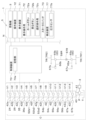
- FIG. FIG. 2 is a schematic diagram of a hydraulic system.
- FIG. 2 is a diagram showing a display device provided in a meter panel.
- FIG. 2 is a diagram showing the entire transmission.
- FIG. 2 is an internal view showing the solenoid proportional valve and the valve body.
- FIG. 2 is an internal view showing the solenoid proportional valve and the valve body.
- 1 is an example of a graph showing the pressure of hydraulic oil supplied to a hydraulic device via an electromagnetic proportional valve when air bubbles are generated in the hydraulic oil in an oil chamber and when no air bubbles are generated.
- FIG. 2 is an internal view showing the solenoid proportional valve and the valve body.
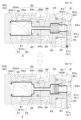
- FIG. 11 is a diagram illustrating the movement of the solenoid proportional valve in the air bleeding mode.
- FIG. 11 is a diagram illustrating the movement of the solenoid proportional valve in the air bleeding mode.
- FIG. 11 is a diagram showing an example of a first selection screen.
- FIG. 11 is a diagram showing an example of a second selection screen.
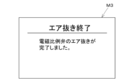
- FIG. 13 is a diagram showing an example of an end screen.
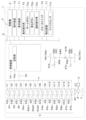
- FIG. 4 is a schematic configuration diagram of a hydraulic system according to a first modified example.
- FIG. 11 is a schematic configuration diagram of a hydraulic system according to a second modified example.
- FIG. 13 is a diagram showing an example of a presentation screen.
- FIG. 13 is a schematic configuration diagram of a hydraulic system according to a third modified example.
- FIG. 13 is a schematic configuration diagram of a hydraulic system according to a fourth modified example.
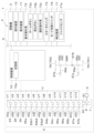
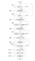
- FIG. 4 is a diagram illustrating a series of processing flows related to the air bleeding mode of the control device.
- FIG. 1 shows an example of a working machine 1.
- a tractor equipped with a working device 20 is used as an example of the working machine 1, but the working machine 1 may also be an agricultural machine such as a rice transplanter for performing agricultural work, a construction machine such as a backhoe for performing construction work, a skid steer loader, a wheel loader, etc.
- the direction in which an operator seated in the driver's seat 6 of the work machine 1 faces is referred to as the forward direction
- the opposite direction is referred to as the rearward direction
- the right side of the operator (the front side in Fig. 1) is referred to as the right side
- the left side of the operator (the back side in Fig. 1) is referred to as the left side
- the horizontal direction that is perpendicular to the fore-aft direction of the work machine 1 (the direction of arrow A3 in Fig. 1) is referred to as the machine width direction (or width direction).
- the work machine 1 is equipped with a machine body (vehicle body) 2, a traveling device 7 having front wheels 7F and rear wheels 7R and supporting the machine body 2 so that it can travel, and a protection mechanism (e.g., a cabin, canopy, etc.) 8 that is disposed above the machine body 2 and surrounds the driver's seat 6 where the operator sits, etc.
- a protection mechanism e.g., a cabin, canopy, etc.
- the aircraft 2 has a prime mover 3, which is a power source, a front frame 4, and a transmission 5.
- the prime mover 3 is a device that generates power (driving force) and is an internal combustion engine such as a gasoline engine or a diesel engine, an electric motor, etc. In this embodiment, the prime mover 3 is a diesel engine.
- the front frame 4 is connected to the engine 3 and protrudes forward from the engine 3.
- the front frame 4 is supported by the front wheels 7F.
- the transmission 5 transmits the driving force generated by the prime mover 3 to the traveling device 7, and is capable of changing the rotation speed of the driving force.
- the transmission 5 can also switch the traveling device 7 between forward and reverse. This allows the transmission 5 to change the propulsive force of the traveling device 7.
- the transmission 5 is connected to the rear of the prime mover 3 and extends rearward from the prime mover 3. The rear of the transmission 5 is also supported by the rear wheel 7F.
- the traveling device 7 is a device having front wheels 7F and rear wheels 7R.
- the rear wheels 7R include a first wheel 7R1 provided on one side (left side) of the machine body 2 in the machine body width direction, and a second wheel 7R2 provided on the other side (right side) of the machine body 2 in the machine body width direction.
- the second wheel 7R2 is separated from the first wheel 7R1 in the machine body width direction.
- the front wheels 7F may be of either a tire type or a crawler type.
- the rear wheels 7R may also be of either a tire type or a crawler type.
- FIG. 2 is a schematic diagram of the hydraulic system S.
- the work machine 1 is equipped with a hydraulic system S, which is a system that drives the work machine 1 with hydraulic oil.
- the work machine 1 (hydraulic system S) is equipped with a control device 70, a display device 71, a hydraulic oil tank T, a hydraulic pump P, a control valve V, and hydraulic equipment C.
- the control device 70 is a device that is composed of electric and electronic circuits, a CPU, programs stored in an MPU, etc.
- the control device 70 controls various devices of the work machine 1.
- the multiple devices mounted on the work machine 1 are connected to the control device 70 via an in-vehicle network N such as CAN, ISOBUS, LIN, or FlexRay.
- the control device 70 is connected to a starter switch 73 and the prime mover 3 provided in the work machine 1, and starts or stops each part including the prime mover 3 in response to the operation of the starter switch 73.
- the starter switch 73 is an operating tool for starting at least the prime mover 3.
- the starter switch 73 is provided inside the protection mechanism 8, and can be operated by an operator seated in the driver's seat 6.
- the control device 70 starts each part provided in the work machine 1.
- the control device 70 stops each part provided in the work machine 1.
- the control device 70 also has a storage unit 70a.
- the storage unit 70a is a non-volatile memory or the like, and stores various information related to the control of the control device 70.
- the display device 71 is a device capable of displaying various information.
- the display device 71 has a liquid crystal panel, a touch panel, or any other panel.
- the display device 71 is a monitor provided in the meter panel 10 provided in front of the driver's seat 6.
- FIG. 3 is a diagram showing a display device provided in the meter panel 10.
- the meter panel 10 is disposed above the column cover of the control console 9 and in front of the steering wheel 11.
- the meter panel 10 is provided with an engine tachometer 10a that displays the RPM of the prime mover 3, a water temperature gauge 10b, a fuel gauge 10c, and a display device 71.
- the display device 71 is connected to the control device 70 and the like via the in-vehicle network N.
- the display device 71 is capable of acquiring various information from devices such as the control device 70 and various sensors that are connected to the in-vehicle network N and displaying the information. In this embodiment, the display device 71 changes the display under the control of the control device 70.
- the work machine 1 is also provided with a display operation tool 72 for operating the display device 71.
- the display operation tool 72 is disposed in a position where it can be operated by the worker seated in the driver's seat 6, for example, in an arm rest disposed to the side of the driver's seat 6 or near the display device 71.
- the display operation device 72 includes a push button switch (tactile switch) that is operated by pressing, a slide switch that is operated by sliding, a dial-shaped switch (dial switch) such as a selector switch with multiple switching positions, etc.
- the display operation device 72 includes a push button switch and a dial switch.
- the push button switches are, for example, a home button 72a for transitioning the display on the display device 71 to a specified initial screen, and a back button 72b for transitioning the display on the display device 71 to the previous screen.
- a dial switch is a selection operation device 72c for operating the selection and confirmation of an item displayed on the display device 71.
- the selection operation device 72c is rotated by the worker to change the switching position, thereby accepting the selection operation of the item displayed on the display device 71. Also, the selection operation device 72c is pressed by the worker to accept the confirmation operation of the selected item.
- a push button switch or a dial switch has been described as an example of the display operation device 72, but the display operation device 72 is not limited to a physical operation device, and may be a display image (graphical interface) displayed on the display device 71 if the display device 71 has a touch panel that accepts operations.
- the display device 71 only needs to be capable of displaying information, and is not limited to a monitor provided within the meter panel 10 as described above.
- the display device 71 may be a terminal display device provided around the operator seated in the driver's seat 6, or may be a mobile terminal carried by the operator.
- the mobile terminal may be a PC or a smartphone (multi-function mobile phone) with relatively high computing power.
- the mobile terminal has a device that communicates either directly or indirectly with the in-vehicle network N, and is capable of acquiring various information from devices connected to the in-vehicle network N via the device and displaying the information.
- the hydraulic oil tank T is a tank that stores hydraulic oil.
- a drain oil passage 40 for draining hydraulic oil is connected to the hydraulic oil tank T.
- the hydraulic pump P is operated by the power (driving force) generated by the prime mover 3 and discharges hydraulic oil.
- the hydraulic pump P is also configured as a fixed displacement gear pump. Specifically, the hydraulic pump P is connected between the hydraulic oil tank T and the discharge oil passage 41, and is capable of discharging the hydraulic oil stored in the hydraulic oil tank T to the discharge oil passage 41.
- pilot oil discharged from hydraulic pump P that is used for control purposes
- pilot pressure the pressure of that pilot oil
- FIG. 2 shows only a single hydraulic pump P
- the work machine 1 hydraulic system S of the work machine 1
- a variable displacement hydraulic pump P may be used as the hydraulic pump P
- the discharge flow rate of the hydraulic pump P may be controlled by load sensing control (control by a load sensing system).
- the control valve V adjusts the flow rate and/or pressure of hydraulic oil supplied from the hydraulic pump P to the hydraulic equipment C.
- the work machine 1 is provided with a number of control valves V corresponding to the hydraulic equipment C mounted on the work machine 1.
- the work machine 1 is equipped with multiple control valves V.
- the control valves V are solenoid valves that operate to change the opening degree when a built-in solenoid is energized or deenergized, operating valves that operate in response to the operation of the operating device 12, or pilot-type switching valves that change the opening degree by moving a spool 83 with pilot oil acting on a pressure receiving section from a solenoid valve.
- the operating device 12 is a lever, various switches, etc.
- the hydraulic equipment C is operated by hydraulic oil discharged from the hydraulic pump P, and drives the work machine 1.
- the work machine 1 is equipped with multiple hydraulic equipment C.
- the hydraulic equipment C is a hydraulic actuator such as a hydraulic cylinder and a hydraulic motor driven by hydraulic oil, a hydraulic clutch that switches between transmission and disconnection of power (driving force) by the hydraulic oil acting on it, a hydraulic pump for traveling in which pilot oil acts on a servo cylinder or the like to change the angle of the swash plate to change the output.
- the hydraulic equipment C is operated by hydraulic oil to drive the work device 20 and/or the traveling device 7, thereby driving the work machine 1. In this embodiment, an example will be described in which the hydraulic equipment C drives both the work device 20 and the traveling device 7, but it is sufficient that the hydraulic equipment C can drive at least one of the work device 20 and the traveling device 7.
- the working machine 1 is equipped with a working device (implement) 20 for performing work.
- the working machine 1 can connect the working device 20 to the front and rear of the machine body 2.
- the working device 20 attached to the front of the machine body 2 is referred to as the "front-mounted working device”
- the working device 20 attached to the rear of the machine body 2 is referred to as the "rear-mounted working device.”
- the front loading work device 20A is, for example, a front loader 21.
- the front loading work device 20A is not limited to a front loader 21, and may be another work device 20 such as a sweeper.
- the front loader 21 has a support frame 22, a boom 23, a boom cylinder 24 (hydraulic equipment C), a work tool 25, and a work tool cylinder 26 (hydraulic equipment C).
- the front loader 21 is also connected to a mounting frame 16 provided at the front of the machine body 2.
- the mounting frame 16, the support frame 22, the boom 23, the boom cylinder 24, and the work tool cylinder 26 are arranged on both sides in the width direction of the machine body 2.
- the boom cylinder 24 and the work tool cylinder 26 are composed of double-acting hydraulic cylinders.
- the support frame 22 is a frame that is detachably connected to the mounting frame 16.
- the boom 23 is supported on the upper part of the support frame 22 so that it can swing freely up and down around an axis that extends in the width direction of the machine body.
- the boom cylinder 24 is installed between the support frame 22 and the boom 23, and swings the boom 23 by extending and retracting.
- the boom cylinder 24 is connected to the first control valve V1 via the first oil passage 42a.
- the first control valve V1 controls the boom cylinder 24 to extend and retract.
- the first control valve V1 is connected to the first oil passage 42a, the drain oil passage 40, and the discharge oil passage 41. By changing the opening degree, the first control valve V1 can adjust the flow rate of hydraulic oil supplied from the hydraulic pump P to the boom cylinder 24, or adjust the flow rate of hydraulic oil discharged from the boom cylinder 24 to the hydraulic oil tank T.
- a bucket is shown as an example of the working tool 25.
- the working tool 25 is provided across the tip side of the left boom 23 and the tip side of the right boom 23, and is swingably connected to the left and right booms 23 to enable lifting (scooping) and lowering (dumping) operations.
- Examples of the work tool 25 include manifold forks, pallet forks, hay forks, bale forks, roll grabs, and container buckets.
- One end of the work tool cylinder 26 is pivoted to the middle of the boom 23, and the other end is connected to the work tool 25 and the tip of the boom 23 via a link mechanism 27, and it swings the work tool 25 by extending and retracting.
- the implement cylinder 26 is connected to the second control valve V2 via the second oil passage 42b.
- the second control valve V2 controls the implement cylinder 26 to extend and retract.
- the second control valve V2 is connected to the second oil passage 42b, the drain oil passage 40, and the discharge oil passage 41. By changing the opening degree, the second control valve V2 can adjust the flow rate of hydraulic oil supplied from the hydraulic pump P to the implement cylinder 26, or adjust the flow rate of hydraulic oil discharged from the implement cylinder 26 to the hydraulic oil tank T.
- the rear-mounted working device 20B may be a tilling device for tilling, a fertilizer spreading device for spreading fertilizer, a pesticide spreading device for spreading pesticide, a harvesting device for harvesting, a harvesting device for cutting grass, etc., a spreading device for spreading grass, etc., a grass collecting device for collecting grass, etc., and a shaping device for shaping grass, etc.
- the working machine 1 is also provided with a coupling device (lifting device) 30 for connecting the rear-mounted working device 20B to the machine body 2.
- the lifting device 30 is provided at the rear of the machine body 2, and can raise and lower the attached rear-mounted working device 20B.
- the lifting device 30 has a lift arm 31, a lower link 32, a top link 33, a lift rod 34, and a lift cylinder 35.
- the front end of the lift arm 31 is supported on the upper rear part of the case (transmission case) that houses the transmission 5 so that it can swing upward or downward.
- the lift arm 31 swings (lifts and lowers) when driven by the lift cylinder 35.
- the lift cylinder 35 is composed of a single-acting hydraulic cylinder.
- the lift cylinder 35 is connected to the third control valve V3 via the third oil passage 42c.
- the third control valve V3 controls the lift cylinder 35 to extend it.
- the third control valve V3 is connected to the third oil passage 42c, the drain oil passage 40, and the discharge oil passage 41.
- the third control valve V3 adjusts the flow rate of hydraulic oil supplied from the hydraulic pump P to the bottom side of the lift cylinder 35 to extend the lift cylinder 35 and raise the rear mounting work device 20B.
- the third control valve V3 lowers the rear mounting work device 20B by its own weight by draining hydraulic oil from the bottom side of the lift cylinder 35 to the hydraulic oil tank T.
- the third control valve V3 holds the rear mounting work device 20B at a predetermined height by not draining hydraulic oil from the lift cylinder 35.
- the front end of the lower link 32 is supported on the rear lower part of the transmission 5 so that it can swing upward or downward.
- the front end of the top link 33 is supported on the rear part of the transmission 5 above the lower link 32 so that it can swing upward or downward.
- the lift rod 34 connects the lift arm 31 to the lower link 32.
- the rear part of the lower link 32 and the rear part of the top link 33 are connected to the rear mounting work device 20B.
- the lift cylinder 35 is driven (extends and retracts)
- the lift arm 31 rises and lowers
- the lower link 32 connected to the lift arm 31 via the lift rod 34 rises and lowers.
- the rear mounting work device 20B swings upward or downward (rises and falls) with the front part of the lower link 32 as a fulcrum.
- At least one of the pair of lift rods 34 of the lifting device 30 may be provided with an angle change unit 36 (hydraulic device C).
- the angle change unit 36 changes the attitude of the rear mounting work device 20B attached to the machine body 2.
- the angle change unit 36 has a change cylinder 36a composed of a hydraulic cylinder.
- the change cylinder 36a is connected to the fourth control valve V4 via the fourth oil passage 42d.
- the fourth control valve V4 controls the change cylinder 36a to expand and contract.
- the fourth control valve V4 is connected to the fourth oil passage 42d, the drain oil passage 40, and the discharge oil passage 41.
- the fourth control valve V4 adjusts the flow rate of hydraulic oil supplied from the hydraulic pump P to the bottom side of the change cylinder 36a to extend the change cylinder 36a, and adjusts the flow rate of hydraulic oil supplied from the hydraulic pump P to the rod side of the change cylinder 36a to contract the change cylinder 36a.
- a three-point link mechanism is exemplified as the lifting device 30, but the connecting device 30 is not limited to a three-point link mechanism and may be, for example, a two-point link mechanism.
- the working machine 1 has been described using a tractor as an example, but if the working machine 1 is a combine harvester, backhoe, or the like, in which the working device 20 is attached to the machine body 2 without the intermediation of the coupling device 30, the working machine 1 does not need to be equipped with the coupling device 30.
- FIG. 4 is a diagram showing the entire transmission 5.
- the transmission 5 is equipped with a main shaft (propeller shaft) 51, a shuttle section 52, a main transmission section 53, an auxiliary transmission section 54, a PTO power transmission section 55, and a front transmission section 56.
- the propeller shaft 51 is rotatably supported by the transmission 5, and driving force is transmitted to the propeller shaft 51 from the crankshaft of the prime mover 3.
- the shuttle section 52 has a shuttle shaft 52a and a forward/reverse switching section 52b.
- the shuttle shaft 52a is connected to the propeller shaft 51, and the driving force is transmitted from the propeller shaft 51.
- the forward/reverse switching unit 52b is composed of, for example, a hydraulic clutch, and switches the rotation direction of the shuttle shaft 52a, i.e., the forward and reverse of the work machine 1, by engaging and disengaging the hydraulic clutch.
- the forward/reverse switching unit 52b has a forward clutch unit 52b1 (hydraulic device C) and a reverse clutch unit 52b2 (hydraulic device C).
- the forward clutch portion 52b1 is connected to the fifth control valve V5 via the fifth oil passage 42e.
- the fifth control valve V5 controls the transmission and disconnection of power by the forward clutch portion 52b1.
- the fifth control valve V5 is connected to the fifth oil passage 42e, the drain oil passage 40, and the discharge oil passage 41.
- the reverse clutch portion 52b2 is connected to the sixth control valve V6 via the sixth oil passage 42f.
- the sixth control valve V6 controls the transmission and disconnection of power by the reverse clutch portion 52b2.
- the sixth control valve V6 is connected to the sixth oil passage 42f, the drain oil passage 40, and the discharge oil passage 41.
- the sixth control valve V6 can adjust the flow rate of hydraulic oil supplied from the hydraulic pump P to the inside of the clutch housing of the reverse clutch portion 52b2, and can adjust the flow rate of hydraulic oil discharged from the clutch housing of the reverse clutch portion 52b2 to the hydraulic oil tank T.
- the main transmission unit 53 is a continuously variable transmission mechanism that changes the speed of the transmitted driving force (rotational driving force) in a stepless manner.
- the continuously variable transmission mechanism has a traveling hydraulic pump 53a (hydraulic device C), a traveling motor 53b (hydraulic motor), and a planetary gear mechanism 53c.
- the traveling hydraulic pump 53a is operated by the driving force transmitted from the output shaft 52c of the shuttle unit 52.
- the traveling hydraulic pump 53a is, for example, an HST pump.
- the traveling hydraulic pump 53a is a swash plate type variable displacement pump having a swash plate 53a1 and a servo cylinder 53a2 to which a pilot pressure acts and which changes the angle of the swash plate 53a1.
- the servo cylinder 53a2 is connected to the seventh control valve V7 via the seventh oil passage 42g.
- the seventh control valve V7 adjusts the pilot pressure acting on the servo cylinder 53a2 to control the swash plate 53a1.
- the seventh control valve V7 is connected to the seventh oil passage 42g, the discharge oil passage 40, and the discharge oil passage 41.
- the seventh control valve V7 adjusts the pilot pressure acting on the servo cylinder 53a2 by changing the opening degree, and can change the output (discharge amount of hydraulic oil) and the discharge direction of the hydraulic oil of the traveling hydraulic pump 53a.
- the seventh control valve V7 connected to the servo cylinder 53a2 is shown as a single block, but if the servo cylinder 53a2 is a double-acting type, there are two seventh control valves V7 for controlling the servo cylinder 53a2, and if the servo cylinder 53a2 is a single-acting type, there is one seventh control valve V7 for controlling the servo cylinder 53a2.
- the travel motor 53b has an output shaft 53b1, and is a motor that rotates and drives the output shaft 53b1 with hydraulic oil discharged from the travel hydraulic pump 53a through an oil passage such as a pipe.
- the speed and direction of rotation of the output shaft 53b1 of the travel motor 53b change depending on the output of the hydraulic oil discharged from the travel hydraulic pump 53a (flow rate, pressure, and discharge direction of the hydraulic oil).
- the planetary gear mechanism 53c is a mechanism made up of multiple gears and power transmission shafts such as input shafts 53c1, 53c2 and output shaft 53c3, and includes an input shaft 53c1 to which the driving force generated by the prime mover 3 is input (transmitted) via the traveling hydraulic pump 53a, etc., an input shaft 53c2 connected to the output shaft 53b1 of the traveling motor 53b and to which the driving force of the traveling motor 53b is input (transmitted), and an output shaft 53c3 that outputs the driving force.
- the planetary gear mechanism 53c transmits the combined driving force of the driving force of the prime mover 3 and the driving force of the traveling motor 53b to the output shaft 53c3.
- the main transmission unit 53 can change the driving force output to the sub-transmission unit 54 by changing the angle of the swash plate 53a1 of the traveling hydraulic pump 53a, the rotation speed of the prime mover 3, etc.
- a continuously variable transmission mechanism is used as the main transmission unit 53, but the main transmission unit 53 may be a stepped transmission mechanism that changes speed using gears.
- the sub-transmission unit 54 is a transmission mechanism having multiple stepped gears (cogwheels) that change the speed of the transmitted rotational driving force.
- the sub-transmission unit 54 changes and outputs (changes the speed of) the rotational driving force transmitted to the sub-transmission unit 54 from the output shaft 53c3 of the planetary gear mechanism 53c by appropriately changing the connection (meshing) of the multiple gears.
- the sub-transmission unit 54 includes an input shaft 54a, a first shift clutch 54b, a second shift clutch 54c, and an output shaft 54d.
- the input shaft 54a is connected to the output shaft 53c3 of the planetary gear mechanism 53c, and is the shaft to which the driving force is input (transmitted) from the output shaft 53c3.
- the input shaft 54a inputs the transmitted driving force to the first shift clutch 54b and the second shift clutch 54c via gears, etc.
- the sub-transmission unit 54 changes the input power by switching between the engagement and disengagement of the first shift clutch 54b and the second shift clutch 54c, and outputs it to the output shaft 54d.
- the sub-transmission unit 54 is capable of two-speed shifting, first gear (low gear) and second gear (high gear), by switching between the engagement and disengagement of the first shift clutch 54b and the second shift clutch 54c.
- the first variable speed clutch 54b is connected to the eighth control valve V8 via the eighth oil passage 42h.
- the eighth control valve V8 controls the transmission and disconnection of power by the first variable speed clutch 54b.
- the eighth control valve V8 is connected to the eighth oil passage 42h, the drain oil passage 40, and the discharge oil passage 41.
- the eighth control valve V8 can adjust the flow rate of hydraulic oil supplied from the hydraulic pump P to the inside of the clutch housing of the first variable speed clutch 54b, and can adjust the flow rate of hydraulic oil discharged from the clutch housing of the first variable speed clutch 54b to the hydraulic oil tank T.
- the second variable-speed clutch 54c is connected to the ninth control valve V9 via the ninth oil passage 42i.
- the ninth control valve V9 controls the transmission and disconnection of power by the second variable-speed clutch 54c.
- the ninth control valve V9 is connected to the ninth oil passage 42i, the drain oil passage 40, and the discharge oil passage 41.
- the output shaft 54d transmits power to the rear wheel differential device 57R.
- the rear wheel differential device 57R rotatably supports the rear axle 58R to which the rear wheels 7R are attached, and drives the rear axle 58R.
- the PTO power transmission unit 55 has a PTO clutch 55a (hydraulic device C), a PTO propulsion shaft 55b, and a PTO speed change unit 55c.
- the PTO clutch 55a is, for example, a hydraulic clutch, and switches between transmitting and disconnecting the power of the propulsion shaft 51 to and from the PTO propulsion shaft 55b by switching the hydraulic clutch on and off.
- the PTO clutch 55a is connected to the tenth control valve V10 via the tenth oil passage 42j.
- the tenth control valve V10 controls the transmission and disconnection of power by the PTO clutch 55a.
- the tenth control valve V10 is connected to the tenth oil passage 42j, the drain oil passage 40, and the discharge oil passage 41.
- the tenth control valve V10 can adjust the flow rate of hydraulic oil supplied from the hydraulic pump P to the inside of the clutch housing of the PTO clutch 55a, and adjust the flow rate of hydraulic oil discharged from the clutch housing of the PTO clutch 55a to the hydraulic oil tank T.
- the PTO transmission unit 55c includes a transmission clutch and multiple gears, and changes and outputs (changes the speed of) the driving force (rotational driving force) input from the PTO propulsion shaft 55b to the PTO transmission unit 55c.
- the PTO transmission unit 55c transmits the rotational driving force to the PTO shaft 59 via gears, etc.
- the front transmission unit 56 has a first front transmission clutch 56a (hydraulic device C) and a second front transmission clutch 56b (hydraulic device C).
- the first front transmission clutch 56a and the second front transmission clutch 56b can switch between transmitting and disconnecting the rotational driving force transmitted from the sub-transmission unit 54.
- the power of the output shaft 54d is transmitted to the first front shift clutch 56a and the second front shift clutch 56b, for example, via gears and a transmission shaft.
- the driving force transmitted to the first front shift clutch 56a and the second front shift clutch 56b is transmitted to the front axle 58F via the front transmission shaft 60.
- the front transmission shaft 60 is connected to the front wheel differential device 57F, which rotatably supports the front axle 58F to which the front wheels 7F are attached, and drives the front axle 58F.
- the first front shift clutch 56a and the second front shift clutch 56b are composed of hydraulic clutches or the like.
- the first front shift clutch 56a is connected to the eleventh control valve V11 via the eleventh oil passage 42k.
- the eleventh control valve V11 controls the transmission and disconnection of power by the first front shift clutch 56a.
- the eleventh control valve V11 is connected to the eleventh oil passage 42k, the drain oil passage 40, and the discharge oil passage 41.
- the eleventh control valve V11 can adjust the flow rate of hydraulic oil supplied from the hydraulic pump P to the inside of the clutch housing of the first front shift clutch 56a, and adjust the flow rate of hydraulic oil discharged from the clutch housing of the first front shift clutch 56a to the hydraulic oil tank T.
- the second front shift clutch 56b is connected to the 12th control valve V12 via the 12th oil passage 42l.
- the 12th control valve V12 controls the transmission and disconnection of power by the second front shift clutch 56b.
- the 12th control valve V12 is connected to the 12th oil passage 42l, the drain oil passage 40, and the discharge oil passage 41.
- the 12th control valve V12 can adjust the flow rate of hydraulic oil supplied from the hydraulic pump P to the inside of the clutch housing of the second front shift clutch 56b, and can adjust the flow rate of hydraulic oil discharged from the clutch housing of the second front shift clutch 56b to the hydraulic oil tank T.
- the second front shift clutch 56b transmits the driving force transmitted from the sub-transmission unit 54 to the front wheels 7F.
- the front wheels 7F and rear wheels 7R are driven by the transmitted driving force in four-wheel drive (4WD), and the rotational speeds of the front wheels 7F and rear wheels 7R are approximately the same (4WD constant speed state, constant speed drive).
- the first front shift clutch 56a transmits the driving force transmitted from the sub-transmission unit 54 to the front wheels 7F.
- the front wheels 7F and rear wheels 7R are driven by the transmitted driving force in four-wheel drive (4WD), and the rotation speed of the front wheels 7F is faster than the rotation speed of the rear wheels 7R (4WD acceleration state, accelerated drive).
- the transmission 5 only needs to be able to switch the travel device 7 between forward and reverse, etc., and its configuration is not limited to the above configuration.
- the braking device 65 that brakes the traveling device 7 will be described in detail as a device having a hydraulic device C that drives the traveling device 7.
- the work machine 1 is equipped with a braking device 65.
- the braking device 65 has a left braking device 65a and a right braking device 65b.
- the left braking device 65a and the right braking device 65b are disk-type braking devices 65 that can be switched between a braking state in which braking is applied and a release state in which braking is released.
- the left braking device 65a is provided on the left side of the rear axle 58R and applies the brakes to the left rear wheel 7R (first wheel 7R1).
- the right braking device 65b is provided on the right side of the rear axle 58R and applies the brakes to the right rear wheel 7R (second wheel 7R2).
- a left brake pedal and a right brake pedal are provided near the driver's seat 6.
- the left connecting member 66a connected to the left brake pedal moves in the braking direction, and the left braking device 65a can be put into a braking state.
- the right connecting member 66b connected to the right brake pedal moves in the braking direction, and the right braking device 65b can be put into a braking state.
- the left connecting member 66a is connected to a left hydraulic actuator 67a (hydraulic device C) that operates with hydraulic oil.
- the left hydraulic actuator 67a is connected to a 13th control valve V13 via a 13th oil passage 42m.
- the 13th control valve V13 controls the braking and non-braking states of the left hydraulic actuator 67a.
- the 13th control valve V13 is connected to the 13th oil passage 42m, the drain oil passage 40, and the discharge oil passage 41.
- the 13th control valve V13 adjusts the pressure of the hydraulic oil acting on the left hydraulic actuator 67a by changing the opening degree, and can operate the left hydraulic actuator 67a to move the left connecting member 66a in the braking direction.
- a right hydraulic actuator 67b (hydraulic device C) that operates with hydraulic oil is connected to the right connecting member 66b.
- the right hydraulic actuator 67b is connected to the 14th control valve V14 via the 14th oil passage 42n.
- the 14th control valve V14 controls the braking state and non-braking state of the right hydraulic actuator 67b.
- the 14th control valve V14 is connected to the 14th oil passage 42n, the drain oil passage 40, and the discharge oil passage 41.
- the 14th control valve V14 adjusts the pressure of the hydraulic oil acting on the right hydraulic actuator 67b by changing the opening degree, and can operate the right hydraulic actuator 67b to move the right connecting member 66b in the braking direction.
- the left braking device 65a and the right braking device 65b can independently brake the left rear wheel 7R (first wheel 7R1) and the right rear wheel 7R (second wheel 7R2) not only by operating the left brake pedal and the right brake pedal, but also by operating the left hydraulic actuator 67a and the right hydraulic actuator 67b.
- the left braking device 65a is provided on the left side of the rear axle 58R
- the right braking device 65b is provided on the right side of the rear axle 58R
- the braking device 65 applies brakes to the rear wheel 7R of the wheels 7F, 7R.
- the braking devices 65 may be provided on the left and right sides of the front axle 58F to apply brakes to the front wheel 7F.
- At least one of the first control valve V1 to the fourteenth control valve V14 described above has an electromagnetic proportional valve SV or an electromagnetic proportional valve SV that operates to change the opening degree by energizing or deenergizing a built-in solenoid based on a control signal (control current) output from the control device 70.
- the electromagnetic proportional valve SV adjusts the flow rate and/or pressure of the hydraulic oil supplied from the hydraulic pump P to the hydraulic equipment C.
- the electromagnetic proportional valve SV in this embodiment is an electromagnetic proportional pressure reducing valve that is connected to the hydraulic oil tank T, the hydraulic pump P, and the hydraulic equipment C, and controls the supply of hydraulic oil from the hydraulic pump P to the hydraulic equipment C and the discharge of hydraulic oil from the hydraulic equipment C to the hydraulic oil tank T.
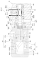
- FIG. 5 is an internal view showing the electromagnetic proportional valve SV and the valve body B.
- the electromagnetic proportional valve SV is mounted in a receiving hole 90 formed in the valve body B. It is mounted in a common valve body B for the control valves V equipped in the work machine 1, but an individual valve body B may be provided for each control valve V.
- the valve body B is formed with a plurality of flow paths 91 that constitute part of the oil paths (discharge oil path 40, discharge oil path 41, and first to fourteenth oil paths 42a to 42n, etc.) connected to the control valves V.
- the valve body B has a plurality of flow paths 91, including a first flow path 91a, a second flow path 91b, and a third flow path 91c.
- the first flow path 91a constitutes a part of the discharge oil path 40 (the end connected to the control valve V).
- the first flow path 91a discharges the hydraulic oil that has flowed in to the hydraulic oil tank T.
- the second flow path 91b constitutes a part of the oil paths (the first oil path 42a to the fourteenth oil path 42n, etc.) connected to the ports of the hydraulic equipment C (the end connected to the control valve V).
- the second flow path 91b allows the hydraulic oil heading to the hydraulic equipment C and the hydraulic oil discharged from the hydraulic equipment C to flow.
- the third flow path 91c constitutes a part of the discharge oil path 41 (the end connected to the control valve V).
- the third flow path 91c allows the hydraulic oil discharged by the hydraulic pump P to flow.
- the solenoid proportional valve SV will be described in detail below.
- the solenoid proportional valve SV has a housing 80, a spool 83 housed in the housing 80, a coil 85 controlled by the control device 70, and a moving part 87 (plunger) that moves the spool 83 by the magnetic flux generated by the coil 85.
- the housing 80 is formed from casting, resin, or the like.
- the housing 80 includes a first housing 80a that houses the spool 83 and is attached to the housing hole 90, and a second housing 80b that houses the moving part 87.
- the housing 80 also has oil chambers E1, E2, DE, multiple ports 81, and a through hole 82 formed therein.
- Oil chambers E1, E2, and DE contain hydraulic oil and their volume changes with the movement of the spool 83.
- the communication state of the multiple ports 81 with the other ports 81 is changed by the spool 83.
- the multiple ports 81 are connected to multiple flow paths 91 formed in the valve body B.
- the communication state of the multiple ports 81 with the other ports 81 is changed by the movement of the spool 83, which changes the connection of the multiple flow paths 91.
- the multiple ports 81 are formed in the first housing 80a.
- Each of the multiple ports 81 is formed in a concave shape.
- the first housing 80a is formed with a first port 81a, a second port 81b, and a third port 81c.
- the first port 81a is a port (tank port) that communicates with the hydraulic oil tank T and is connected to the first flow path 91a.
- the second port 81b is a port that communicates with the hydraulic device C and is connected to the second flow path 91b.
- the third port 81c is a port (pump port) that connects with the hydraulic pump P and is connected to the third flow path 91c.
- the through hole 82 is an annular (cylindrical) wall portion that extends from one end of the housing 80 (the end on the left side of the paper in FIG. 5) to the other end (the end on the right side of the paper in FIG. 5).
- the through hole 82 is formed from the first housing 80a to the second housing 80b.
- a spool 83 and a moving part 87 are inserted into the through hole 82, and the spool 83 and the moving part 87 move inside the through hole 82 from one end to the other end and from the other end to the one end.
- the first housing 80a has a valve hole 82a that constitutes part of the through hole 82, and the first port 81a to the third port 81c reach (are connected to) it.
- the valve hole 82a is formed by an annular wall portion formed inside the first housing 80a.
- the spool 83 can change the communication state of the first port 81a to the third port 81c by moving in the longitudinal direction of the through hole 82 (from one end to the other end inside the through hole 82, and from the other end to the first end).
- the spool 83 is formed in a cylindrical shape. In this embodiment, the spool 83 moves inside the through hole 82 to switch between a discharge position 83A that communicates with the first port 81a and the second port 81b, and a supply position 83B that communicates with the second port 81b and the third port 81c.
- Figure 5 shows the state in which the spool 83 is located at the discharge position 83A
- Figure 6 shows the state in which the spool 83 is located at the supply position 83B
- Figure 6 is an internal view showing the solenoid proportional valve SV and the valve body B.
- a first land 83a to a fourth land 83d are formed on the outer circumferential surface of the spool 83 in the longitudinal direction.
- the first land 83a to the fourth land 83d are formed to have approximately the same outer diameter.
- a connection portion 83e for connecting the first port 81a and the second port 81b is formed between the second land 83b and the third land 83c.
- the connection portion 83e can overlap (coincide) with the first port 81a, the second port 81b, and the third port 81c.
- connection portion 83e overlaps the first port 81a and the second port 81b.
- the second land 83b and the third land 83c change the port area of the first port 81a and the second port 81b in response to the longitudinal movement of the spool 83.
- connection portion 83e overlaps the second port 81b and the third port 81c.
- the second land 83b and the third land 83c change the port area of the second port 81b and the third port 81c in response to the longitudinal movement of the spool 83.
- the spool 83 abuts against the second housing 80b (solenoid core 86 described below) to restrict movement to one end, and abuts against the inner wall of the valve body B to restrict movement to the other end.
- the solenoid proportional valve SV also has an elastic member 84 (e.g., a spring) that moves the spool 83 to the discharge position 83A.
- the spring is provided between the first housing 80a and the second housing 80b, and moves the spool 83 to the other end.
- the coil 85 is a solenoid built into the electromagnetic proportional valve SV, and is demagnetized or excited based on a control signal output from the control device 70 to generate a magnetic flux.
- the coil 85 is fixed to the housing 80 (second housing 80b).
- a solenoid core 86 is provided between the first housing 80a and the second housing 80b of the housing 80.
- the solenoid core 86 is fixed to the other end of the second housing 80b by crimping. In other words, the solenoid core 86 forms part of the inner wall of the housing 80 (second housing 80b).
- the first housing 80a is fixed to the other end of the solenoid core 86 by crimping.
- the solenoid core 86 is magnetized when the coil 85 is excited, and is attracted to the moving part 87.
- the solenoid core 86 is formed with an insertion hole 86a that constitutes a part (midway part) of the through hole 82.
- a shaft 88 which will be described later, is inserted into the insertion hole 86a.
- the moving part 87 is a magnetic body, and is a plunger that moves longitudinally relative to the housing 80 due to the magnetic flux generated by the coil 85.
- the moving part 87 is magnetized when the coil 85 is excited, and is attracted to the solenoid core 86.
- a shaft 88 is connected to the other end of the moving part 87, and is connected to one end of the spool 83 via the shaft 88. As a result, the spool 83 is moved by the movement of the moving part 87.
- the moving part 87 is accommodated in an accommodating section E formed in the housing 80 (second housing 80b).
- the storage section E contains the moving part 87 together with hydraulic oil, and has oil chambers E1 and E2 partitioned by the moving part 87.
- the oil chambers E1 and E2 of the storage section E have an area (first area E1) partitioned by the side wall section 80b1, the peripheral wall section 80b2, and the moving part 87, and an area (second area E2) partitioned by the moving part 87, the peripheral wall section 80b2, and one end of the solenoid core 86.
- the volumes of the first area E1 and the second area E2 change in accordance with the movement of the moving part 87 (spool 83).
- the housing 80 is formed with a communication passage 89 that connects the oil chamber (first region E1 and second region E2) with the periphery of the spool 83 (valve hole 82a).
- the communication passage 89 is connected to the tank port 81a, and in this embodiment, it is connected to the tank port 81a via the valve hole 82a.
- the communication passage 89 includes a gap formed between the housing 80 and the moving part 87, and in this embodiment, the gap includes a first gap 89a and a second gap 89b.
- the first gap 89a is a gap formed between the moving portion 87 and the peripheral wall portion 80b2.
- the outer diameter of the moving portion 87 is less than the inner diameter of the peripheral wall portion 80b2, and the first gap 89a between the moving portion 87 and the peripheral wall portion 80b2 communicates with the first region E1 and the second region E2.
- the second gap 89b is a gap formed between the shaft 88 and the insertion hole 86a.
- the outer diameter of the shaft 88 is less than the inner diameter of the insertion hole 86a, and the second gap 89b between the shaft 88 and the insertion hole 86a communicates between the second region E2 and the valve hole 82a.
- the first region E1 communicates with the valve hole 82a via the first gap 89a, the second region E2, and the second gap 89b.
- the communication passage 89 that communicates the first region E1 with the valve hole 82a includes the second region E2.
- the second region E2 communicates with the valve hole 82a via the second gap 89b.
- a groove 89c may be formed on the outer circumferential surface of the moving portion 87 from one end to the other end.
- the groove 89c constitutes a part of the communication passage 89, and the groove 89c communicates the first region E1 with the second region E2 separately from the first gap 89a.
- the control device 70 moves the moving part 87 from a first position 87A on one side of the axial direction to a second position 87B on the other side. This causes the spool 83 to change the communication state of the first port 81a to the third port 81c.
- the normal mode is the mode in which the work machine 1 performs work.
- the control device 70 in normal mode controls the solenoid proportional valve SV in response to the operation of the operating device 12.
- the first position 87A is a position where the pressure of the hydraulic oil supplied from the hydraulic pump P to the hydraulic equipment C via the electromagnetic proportional valve SV is zero.
- the first position 87A is an initial position where the control device 70 outputs a demagnetization signal to the coil 85 (electromagnetic proportional valve SV) and no power is supplied to the coil 85, and when the moving part 87 is located at the first position 87A, the spool 83 switches to the discharge position 83A.
- this is a position where the spool 83 is moved to one end by the elastic member 84 (a position where the spool 83 abuts against the solenoid core 86).
- the second position 87B is a position where the pressure of the hydraulic oil that operates the hydraulic device C is maximum. That is, the second position 87B is a position when the hydraulic pump P discharges hydraulic oil at the maximum pressure that it can discharge.
- the spool 83 switches to the supply position 83B.
- the second position 87B is a position where the moving part 87 is away from the solenoid core 86 and does not abut against the valve body B.
- the opening of the solenoid proportional valve SV is less than maximum.
- the length (distance d1) between the moving part 87 located at the first position 87A and the side wall part 80b1 is shorter than the length (distance d2) between the moving part 87 located at the second position 87B and the side wall part 80b1 (d1 ⁇ d2).
- the current value that the control device 70 outputs to the coil 85 when moving the moving part 87 to the second position 87B is referred to as the first current value.
- the normal mode may be any mode in which the work machine 1 performs work, and when the work machine 1 is operated remotely, the control device 70 in the normal mode controls the solenoid proportional valve SV in response to the operation of the remote control device by the remote operator. Furthermore, when the work machine 1 is equipped with a sensing device that senses the surroundings of the work machine 1 and the control device 70 controls the work machine 1 autonomously (when the work machine 1 performs automatic operation), the control device 70 in the normal mode controls the solenoid proportional valve SV based on the sensing results of the sensing device.
- FIG. 7 is an example of a graph showing the pressure of the hydraulic oil supplied to the hydraulic equipment C via the solenoid proportional valve SV when air bubbles have occurred in the hydraulic oil in the oil chambers E1 and E2 (when air has been mixed in the hydraulic oil) and when no air bubbles have occurred (when no air has been mixed in the hydraulic oil).
- the horizontal axis indicates elapsed time
- the vertical axis indicates the pressure of the hydraulic oil supplied to the hydraulic equipment C via the solenoid proportional valve SV.
- pressure sensors are provided in the oil passages (first oil passage 42a to fourteenth oil passage 42n, etc.) connecting the solenoid proportional valve SV and the hydraulic equipment C, and pressure changes are shown based on the detection results of detecting the pressure of the hydraulic oil flowing through the oil passages.
- the control device 70 of this embodiment has an air bleeding mode to reduce the effect on the hydraulic device C of air trapped in the hydraulic oil in the oil chamber.
- the control device 70 controls the coil 85 to move the moving part 87 back and forth multiple times in the axial direction of the spool 83.
- the moving part 87 can move the surrounding air bubbles by moving.
- the hydraulic oil in the oil chambers E1 and E2 can be pushed out to the outside of the oil chambers E1 and E2 (to the spool 83 side) through the communication passage 89 and discharged, or the hydraulic oil on the spool 83 side that does not contain air bubbles can be sucked into the oil chambers E1 and E2 through the communication passage 89. Therefore, by moving the moving part 87 back and forth multiple times, the hydraulic oil with the dissolved air bubbles can be discharged to the outside of the oil chambers E1 and E2.
- FIG. 8 is an internal view showing the solenoid proportional valve SV and the valve body B.
- the third position 87C is a position on the other end side than the second position 87B, and in this embodiment, the moving part 87 abuts against the inner wall (solenoid core 86) of the housing 80, and is a terminal position where movement to one axial end is restricted.
- the spool 83 is at a full stroke position from the initial position (discharge position 83A).
- the length (distance d3) between the moving part 87 located at the third position 87C and the side wall part 80b1 is longer than the distances d1 and d2 (d3>d2>d1).
- the current value that the control device 70 outputs to the coil 85 when moving the moving part 87 to the third position 87C is referred to as the second current value.
- the control device 70 repeatedly outputs an excitation signal that outputs a current of the second current value to the coil 85, and a demagnetization signal that outputs no current, thereby moving the moving part 87 back and forth multiple times from the first position 87A to the third position 87C.
- the control device 70 outputs the excitation signal and the demagnetization signal for the same period of time.
- the control device 70 repeats a process of outputting an excitation signal for 0.2 seconds and then outputting a demagnetization signal for 0.2 seconds (hereinafter referred to as a series of processes).
- the time for which the control device 70 outputs the excitation signal and demagnetization signal in the air bleeding mode is not limited to 0.2 seconds, and a different number of times may be defined for each control valve V, or the time may be changed to any value by operating an interface such as the display device 71.
- Figure 9 is a diagram explaining the movement of the solenoid proportional valve SV in the air bleeding mode.
- Figure 9 also shows the flow of hydraulic oil (flows R3 and R4) when the control device 70 reciprocates the moving part 87 from the first position 87A to the third position 87C in the air bleeding mode.
- the upper diagram in Figure 9 shows the state in which the moving part 87 is located at the first position 87A
- the lower diagram in Figure 9 shows the state in which the moving part 87 is located at the third position 87C.
- the control device 70 When the control device 70 outputs a demagnetization signal to the coil 85 and then outputs an excitation signal, the magnetic flux generated by the coil 85 causes the solenoid core 86 to attract the moving part 87, and the moving part 87 moves from the first position 87A to the third position 87C, transitioning from the upper diagram to the lower diagram in FIG. 9.
- the moving part 87 By moving from the first position 87A to the third position 87C, the moving part 87 entrains air bubbles around the first region E1, the groove portion 89c, and the second region E2, and moves the air bubbles from one end of the first region E1, the groove portion 89c, and the second region E2 to the other end.
- the shaft 88 entrains air bubbles remaining in the insertion hole 86a (second gap 89b), and moves the air bubbles from the second gap 89b to the valve hole 82a.
- the spool 83 draws in the air bubbles that are trapped in the valve hole 82a and moves them to the second flow path 91b.
- the volume of the first region E1 increases and the pressure in the first region E1 decreases, allowing the hydraulic oil in the valve hole 82a that does not contain air bubbles to be sucked into the oil chambers E1 and E2.
- the control device 70 when the control device 70 outputs an excitation signal to the coil 85 and then a demagnetization signal, the spool 83 is moved to the discharge position 83A by the elastic member 84, and the moving part 87 is moved to the first position 87A so as to transition from the lower diagram to the upper diagram of FIG. 9.
- the volume of the first region E1 becomes smaller, the pressure in the first region E1 increases, and the hydraulic oil in the first region E1 flows out to the second region E2 through the first gap 89a and the groove part 89c.
- the air bubbles that flow into the second region E2 further flow out to the valve hole 82a through the second region E2 and the second gap 89b.
- the hydraulic oil flows from the first region E1 toward the valve hole 82a (flow R3), and the air bubbles generated in the hydraulic oil in the oil chambers E1 and E2 can be discharged from the oil chambers E1 and E2.
- the control device 70 moves the moving part 87 back and forth a predetermined number of times, and then ends the air bleeding mode. That is, the control device 70 repeats the series of processes a predetermined number of times, and moves the moving part 87 back and forth a predetermined number of times. The control device 70 counts the number of times the series of processes are performed, and when the count reaches the predetermined number, the count is set to zero. In this embodiment, the control device 70 repeats the series of processes a predetermined number of times, 420 times, and moves the moving part 87 back and forth 420 times from the first position 87A to the third position 87C.
- the number of times that the control device 70 repeats the series of processes in the air bleeding mode is not limited to 420 times, and a different number may be defined for each control valve V, or the number may be changed to any value by operating an interface such as the display device 71.
- the work machine 1 (hydraulic system S of the work machine 1) is equipped with a first operating tool that accepts operations.
- the control device 70 allows switching to the air bleeding mode when the second operating tool (e.g., starter switch 73) is operated together with the first operating tool.
- the first operating tool is an operating tool different from the second operating tool 74, for example, the display operating tool 72.
- the first operating tools 72a and 72b are the home button 72a and the back button 72b, and the control device 70 allows switching to the air bleeding mode when the home button 72a, the back button 72b, and the starter switch 73 are operated simultaneously.
- the operation of operating the second operating tool 74 together with the above-mentioned first operating tools 72a and 72b will be referred to as a "confirmation operation.”
- control device 70 allows switching to the air bleeding mode when the home button 72a and the back button 72b as the first operating device 72a, 72b and the starter switch 73 as the second operating device 74 are operated simultaneously, but the first operating devices 72a, 72b may be a single switch, and the control device 70 may allow switching to the air bleeding mode when either the home button 72a or the back button 72b and the starter switch 73 are operated simultaneously.
- control device 70 may also allow switching to the air removal mode when the home button 72a and the back button 72b are operated for a predetermined period of time (e.g., 2 seconds).
- the operator performs the above-mentioned confirmation operation and operates the display device 71, whereby the control device 70 is switched to the air bleeding mode.
- the control device 70 causes the display device 71 to display selection screens M1 and M2 as shown in Figures 10 and 11.
- the selection screens M1 and M2 are display screens used by dealers and manufacturers to perform maintenance on the work machine 1, and display items (graphical interfaces) for selecting the mode to switch to.
- the display device 71 displays a first selection screen M1 that displays a classification block 100 for selecting the category to which each mode belongs.
- the first selection screen M1 displays a classification block 100 (first classification block 101) for selecting an automatic adjustment mode including switching to an air bleeding mode.
- the first selection screen M1 also displays a classification block 100 (second classification block 102) for selecting a tester mode that displays information on each part of the working machine 1, a classification block 100 (third classification block 103) for selecting a diagnosis mode that diagnoses the operation of each part of the working machine 1, a classification block 100 (fourth classification block 104) for selecting a failure history mode that checks the failure history (failure history) of the working machine 1, a classification block 100 (fifth classification block 105) for selecting a setting mode that sets each part of the working machine 1, and a classification block 100 (sixth classification block 106) for selecting a manual adjustment mode that manually adjusts the setting values for controlling the working machine 1.
- classification blocks 100 displayed on the first selection screen M1 are just an example, and it is sufficient to display at least the first classification block 101.
- Other classification blocks 100 may be displayed, and the combination of classification blocks 100 to be displayed is not limited to the first classification block 101 to the sixth classification block 106.
- the display device 71 transitions the display from the first selection screen M1 to the second selection screen M2.
- the second selection screen M2 is a screen for selecting a mode included in the automatic adjustment mode.
- the second selection screen M2 displays a selection block 110 for selecting a mode including the air bleeding mode and other automatic adjustment modes.
- the second selection screen M2 displays second selection blocks 112 to sixth selection blocks 116 for selecting switching to modes for calibrating various sensors.
- the control device 70 acquires the operation signal and switches to the air bleeding mode.
- the control device 70 switches to the air bleeding mode and repeats the series of processes a predetermined number of times (420 times), then ends the air bleeding mode and switches to the normal mode.
- the display device 71 displays a screen M3 indicating that the mode has been ended. Specifically, when the air bleeding mode ends, the control device 70 causes the display device 71 to display an ending screen M3.
- FIG. 12 is a diagram showing an example of the ending screen M3. The ending screen M3 indicates that the air bleeding mode has ended.
- the display device 71 may transition to the second selection screen M2 instead of the end screen M3, as long as it can let the operator know that the air bleeding mode has ended.
- FIG. 13 is a schematic diagram of the hydraulic system S in the first modified example.
- the mode changeover switch 75 is connected to the control device 70, and outputs an operation signal to the control device 70 in response to the operation of the operator.
- the mode changeover switch is a push button switch (tactile switch), a slide switch, a selector switch, or another dial-shaped switch (dial switch), etc.
- the control device 70 may also be communicably connected to an external terminal 120, and may be allowed to switch to the air bleeding mode in response to a signal output from the external terminal 120.
- FIG. 14 is a schematic diagram of the hydraulic system S in the second modified example. As shown in FIG. 14, the hydraulic system S (working machine 1) of the working machine 1 is equipped with a communication device 76.
- the communication device 76 is a device that communicates with the external terminal 120 via a wired or wireless connection.
- the external terminal 120 is a terminal such as a PC provided at a dealer or manufacturer that performs maintenance on the working machine 1.
- the communication device 76 has a connector 76a for connecting a cable for communicating with the external terminal 120, and the control device 70 communicates with the external terminal 120 by wire via the communication device 76.
- the worker operates the external terminal 120 to switch to the air bleeding mode, and the external terminal 120 outputs a signal (instruction signal) to the control device 70 via the communication device 76, and the control device 70 switches to the air bleeding mode in response to the instruction signal.
- the control device 70 only needs to switch to the air bleeding mode based on at least a signal output from the external terminal 120, and may switch to the air bleeding mode when it receives a signal (communication permission signal) from the external terminal 120 via the communication device 76 and establishes communication by responding to the communication permission signal.
- a signal communication permission signal
- the hydraulic system S of the work machine 1 includes a detection device 77 that detects an abnormality in the solenoid proportional valve SV and/or the hydraulic equipment C, and the display device 71 may display a screen M4 suggesting a transition to the air bleeding mode when the detection device 77 detects an abnormality.
- the detection device 77 detects that an abnormality has occurred in the hydraulic equipment C based on the vibration of the hydraulic equipment C.
- the detection device 77 is, for example, a gyro sensor 77a that is attached to the hydraulic equipment C and detects angular velocities in three axes (X, Y, and Z axes).
- the gyro sensor 77a is connected to the control device 70 and outputs a detected signal (detection signal) to the control device 70.
- the control device 70 determines that the fluctuation in the detection signal output from the gyro sensor 77a exceeds a predetermined threshold, for example, it determines that abnormal vibration is occurring in the hydraulic equipment C.
- the control device 70 determines that an abnormality is occurring in the hydraulic equipment C, it causes the display device 71 to display a presentation screen M4 as shown in FIG. 15.
- FIG. 15 is a diagram showing an example of the presentation screen M4. A message is displayed on the presentation screen M4 encouraging the user to enter the air bleeding mode.
- the detection device 77 is not limited to the gyro sensor 77a attached to the hydraulic equipment C.
- the detection device 77 may detect that an abnormality has occurred in the solenoid proportional valve SV based on the pressure of the hydraulic oil supplied from the solenoid proportional valve SV to the hydraulic equipment C.
- the detection device 77 may be a pressure sensor 77b provided in the oil passage (first oil passage 42a to fourteenth oil passage 42n, etc.) connecting the solenoid proportional valve SV and the hydraulic equipment C.
- FIG. 16 is a schematic diagram of the hydraulic system S in the third modified example.
- the pressure sensor 77b is connected to the control device 70 and outputs a detected signal (detection signal) to the control device 70.
- a detected signal detection signal
- the control device 70 determines that the fluctuation in the detection signal output from the pressure sensor 77b exceeds a predetermined threshold, it determines that hydraulic pulsation has occurred in the hydraulic oil supplied from the solenoid proportional valve SV to the hydraulic device C, and that an abnormality has occurred in the solenoid proportional valve SV.
- the control device 70 may also determine whether the solenoid proportional valve SV needs to be replaced, and the display device 71 may display a screen (presentation screen M4) that indicates a transition to the air bleeding mode when the control device 70 determines that the solenoid proportional valve SV needs to be replaced.
- Figure 17 is a schematic diagram of the hydraulic system S in the fourth modified example.
- a diagnostic circuit 78 that determines whether or not the solenoid proportional valve SV is connected is connected to the control device 70, and the control device 70 determines whether or not the solenoid proportional valve SV has been replaced based on the diagnosis result of the diagnostic circuit 78. Specifically, when the control device 70 determines based on the diagnosis result of the diagnostic circuit 78 that the solenoid proportional valve SV has been disconnected from a connected state and then reconnected, it determines that the solenoid proportional valve SV has been replaced. When the control device 70 determines that the solenoid proportional valve SV has been replaced, it causes the display device 71 to display the presentation screen M4.
- the control device 70 switches to the air bleeding mode in response to a specific operation (such as a confirmation operation or an operation of the display device 71)
- the switching to the air bleeding mode may be restricted if a specific condition is not met.
- the control device 70 restricts the switching to the air bleeding mode if power transmission is not cut off in any part of the power transmission path (transmission device 5) from the prime mover 3 to the traveling device 7.
- FIG. 18 is a diagram explaining a series of process flows related to the air bleeding mode of the control device 70.
- the series of processes shown in FIG. 18 are executed by the CPU based on a software program pre-stored in the memory of the control device 70.
- the control device 70 determines whether or not an abnormality has occurred in the solenoid proportional valve SV and/or the hydraulic equipment C (S1).
- the control device 70 determines that an abnormality has occurred in the solenoid proportional valve SV and/or the hydraulic equipment C based on the detection signal output from the detection device 77 (S1: Yes)
- it causes the display device 71 to display the presentation screen M4 (S2).
- the control device 70 judges whether the first operating device 72a, 72b and the second operating device 74 have been operated to perform a confirmation operation (S3). If the control device 70 judges that the home button 72a, the back button 72b, and the starter switch 73 have been simultaneously operated to perform a confirmation operation (S3: Yes), it causes the display device 71 to display the first selection screen M1 (S4).
- the control device 70 When the first classification block 101 is selected on the first selection screen M1 (S5: Yes), the control device 70 causes the display device 71 to display the second selection screen M2 (S6). Then, when the first selection block 111 on the second selection screen M2 is selected (S7: Yes), the control device 70 switches to the air bleeding mode (S8).
- control device 70 When the control device 70 switches to the air bleeding mode (S8), it outputs an excitation signal to the coil 85 for a predetermined time (0.2 seconds) and outputs a demagnetization signal to the coil 85 for a predetermined time (0.2 seconds) (S9).
- control device 70 performs the series of processes in S10, it counts the number of times the series of processes has been performed and determines whether the number of times the series of processes has been performed has reached a predetermined number (420 times) (S10).
- the control device 70 repeats the series of processes (S9) until the series of processes has been performed a predetermined number of times (S10: No), and when it determines that the series of processes has been performed a predetermined number of times (S10: Yes), it ends the air bleeding mode (S11).
- control device 70 When the control device 70 ends the air bleeding mode (S11), it switches to the normal mode (S12). The control device 70 also causes the display device 71 to display the end screen M3 (S13).
- the steps S9 to S10 in the process flow related to the air bleeding mode shown in FIG. 18 correspond to the steps of moving the moving part 87 back and forth multiple times.
- the first region E1 and the second region E2 partitioned by the moving portion 87 are described as examples of oil chambers whose volumes change with the movement of the spool 83.
- the oil chamber may be any portion that contains hydraulic oil and whose volume changes with the movement of the spool 83, and may be, for example, a damper oil chamber DE that is partitioned by the spool 83 and suppresses vibration of the spool 83, as shown in FIG. 5, etc.
- the damper oil chamber DE is an area partitioned by the accommodation hole 90 of the valve body B, the fourth land 83d of the spool 83, and the through hole 82 (valve hole 82a).
- a preferred embodiment of the present invention provides a hydraulic system S of a work machine 1, a work machine 1, and a control method for the work machine 1, as described in the following items.
- a control device 70 for controlling the electromagnetic proportional valve SV wherein the electromagnetic proportional valve SV has a housing 80, a spool 83 accommodated in the housing 80, a coil 85 controlled by the control device 70, and a moving part 87 for moving the spool 83 by a magnetic flux generated by the coil 85, and the housing 80 is formed with oil chambers E1, E2, DE in which hydraulic oil is accommodated and whose volume varies with the movement of the spool 83, and the control device 70 has an air bleeding mode in which the coil 85 is controlled to move the moving part 87 back and forth a plurality of times in the axial direction of the spool 83.
- the control device 70 moves the moving part 87 back and forth multiple times in air bleeding mode, thereby reducing the impact on the hydraulic equipment C caused by air getting into the hydraulic oil in the oil chambers E1, E2, and DE.
- the control device 70 in a normal mode, moves the moving part 87 from a first position 87A on one side of the axial direction to a second position 87B on the other side, and, in the air bleeding mode, moves the moving part 87 back and forth multiple times from the first position 87A to a third position 87C, which is a position further away from the second position 87B.
- the moving part 87 in normal mode, can be prevented from contacting or adhering to the inner wall of the housing 80, while in air bleeding mode, the moving part 87 moves back and forth, so that air bubbles around the moving part 87 can be moved from the oil chambers E1, E2, and air bubbles in the oil chambers E1, E2, and DE can be dissolved into the hydraulic oil in the oil chambers E1, E2, and DE. Therefore, by appropriately switching between the normal mode and the air bleeding mode, it is possible to both suppress shocks and adhesion during operation of the solenoid proportional valve SV and reduce the impact on the hydraulic equipment C caused by air getting caught in the hydraulic oil in the oil chambers E1, E2, and DE.
- the moving part 87 can be prevented from contacting or adhering to the inner wall of the housing 80 without restricting the operation of the hydraulic device C.
- the moving part 87 moves a relatively long distance from the first position 87A to the third position 87C, so that the air bubbles around the moving part 87 can be moved widely.
- the fluctuation in the volume of the oil chambers E1, E2, DE i.e., the fluctuation in the pressure applied to the hydraulic oil in the oil chambers E1, E2, DE, can be made relatively large, so that the air bubbles in the oil chambers E1, E2, DE can be separated into smaller bubbles and dissolved in the hydraulic oil.
- the electromagnetic proportional valve SV has a solenoid core 86 that attracts the moving part 87 by the magnetic flux generated by the coil 85 and that forms part of the inner wall of the housing 80, and the third position 87C is a terminal position where the moving part 87 abuts against the solenoid core 86.
- the hydraulic system S of the work machine 1 in item 5 allows the moving part 87 to move a relatively long distance from the first position 87A to the third position 87C more reliably, and allows the fluctuation in the volume of the oil chambers E1, E2, and DE to be relatively large.
- the moving part 87 moves a relatively long distance from the first position 87A to the third position 87C, so the air bubbles around the moving part 87 can be moved widely.
- the fluctuation in the volume of the oil chambers E1, E2, and DE i.e., the fluctuation in the pressure applied to the hydraulic oil in the oil chambers E1, E2, and DE, can be made relatively large.
- the air bubbles in the oil chambers E1, E2, and DE can be separated into smaller bubbles and dissolved in the hydraulic oil.
- the moving part 87 moves a relatively long distance from the first position 87A to the third position 87C, so the air bubbles around the moving part 87 can be moved widely.
- the fluctuation in the volume of the oil chambers E1, E2, and DE i.e., the fluctuation in the pressure applied to the hydraulic oil in the oil chambers E1, E2, and DE, can be made relatively large.
- the air bubbles in the oil chambers E1, E2, and DE can be separated into smaller bubbles and dissolved in the hydraulic oil.
- the pressure of the hydraulic oil in the oil chambers E1 and E2 increases as the moving part 87 moves back and forth multiple times. This allows air bubbles to dissolve inside the hydraulic oil.
- the movement of the moving part 87 allows the hydraulic oil in the oil chambers E1, E2 to be pushed out of the oil chambers E1, E2 (around the spool 83, etc.) through the communication passage 89 and discharged, and the hydraulic oil on the spool 83 side to be sucked into the oil chambers E1, E2 through the communication passage 89. Therefore, by the moving part 87 moving back and forth multiple times, the hydraulic oil with the air bubbles dissolved therein can be discharged to the outside of the oil chambers E1, E2.
- the moving part 87 moves, so that the hydraulic oil in the oil chambers E1, E2 can be discharged to the hydraulic oil tank T via the communication passage 89 and the tank port 81a, and the hydraulic oil in the hydraulic oil tank T can be sucked into the oil chambers E1, E2 via the communication passage 89 and the tank port 81a.
- a work machine 1 comprising: a hydraulic system S for a work machine 1 described in any one of items 1 to 10; a machine body 2 on which the hydraulic pump P, the hydraulic device C, and the solenoid proportional valve SV are mounted; and a work device 20 and/or a traveling device 7 that are provided on the machine body 2 and driven by the hydraulic device C.
- the air bleeding mode can be used to dissolve air bubbles in the oil chambers E1, E2, and DE into the hydraulic oil in those oil chambers E1, E2, and DE, thereby preventing shocks and abnormal noises caused by air bubbles getting into the oil chambers E1, E2, and DE when the hydraulic equipment C is operating.
- the work machine 1 described in item 11 is equipped with a first operating device 72a, 72b that accepts operation, a prime mover 3 that supplies power to the hydraulic pump P, and a second operating device 74 that is different from the first operating devices 72a, 72b and is used to start the prime mover 3, and the control device 70 is allowed to switch to the air bleeding mode when the second operating device 74 is operated together with the first operating devices 72a, 72b.
- switching to the air bleeding mode involves starting the prime mover 3, so the control device 70 can be prevented from switching to the air bleeding mode while the working machine 1 is working with the working device 20 or traveling with the traveling device 7.
- the control device 70 can be communicatively connected to an external terminal 120, and the work machine 1 is allowed to switch to the air bleeding mode in response to a signal output from the external terminal 120.
- the control device 70 since it is necessary to connect the external terminal 120 to switch to the air bleeding mode, it is possible to prevent the control device 70 from switching to the air bleeding mode while the work machine 1 is performing work using the work device 20 or traveling using the travel device 7.
- the work machine 1 of item 14 reduces the impact on the hydraulic equipment C caused by air getting caught in the hydraulic oil in the oil chambers E1, E2, and DE without requiring any operation by the operator.
- the work machine 1 described in item 14 is provided with a display device 71 for displaying information, and when the control device 70 ends the air bleeding mode, the display device 71 displays a screen indicating that the air bleeding mode has been ended.
- the work machine 1 is described in any one of items 11 to 15, and is equipped with a display device 71 that displays information, and a detection device 77 that detects abnormalities in the electromagnetic proportional valve SV and/or the hydraulic equipment C, and the display device 71 displays a screen suggesting transition to the air bleeding mode when the detection device 77 detects the abnormality.
- the working machine 1 is described in any one of items 11 to 16, and is provided with a display device 71 that displays information, the control device 70 determines whether the electromagnetic proportional valve SV needs to be replaced, and the display device 71 displays a screen that suggests transitioning to the air bleeding mode when the control device 70 determines whether the electromagnetic proportional valve SV needs to be replaced.
- a control method for a working machine (1) comprising: a hydraulic pump (P); a hydraulic device (C) that is operated by hydraulic oil discharged by the hydraulic pump (P) and drives the working machine (1); an electromagnetic proportional valve (SV) that forms oil chambers (E1, E2, DE) in which hydraulic oil is stored and whose volume varies with movement of a spool (83) and that adjusts the flow rate and/or pressure of the hydraulic oil supplied from the hydraulic pump (P) to the hydraulic device (C); and a control device (70) that controls the electromagnetic proportional valve (SV), the control method for the working machine (1) comprising: a control device (70) that controls a coil (85) of the electromagnetic proportional valve (SV), and causes a moving part (87) that presses the spool (83) with a magnetic flux generated by the coil (85) to move back and forth multiple times in the axial direction of the spool (83).
- the control device 70 moves the moving part 87 back and forth multiple times in air bleeding mode, so that the air bubbles can be dissolved inside the hydraulic oil, and the impact on the hydraulic equipment C caused by air getting caught in the hydraulic oil in the oil chambers E1, E2, and DE can be reduced.
Landscapes
- Engineering & Computer Science (AREA)
- General Engineering & Computer Science (AREA)
- Mechanical Engineering (AREA)
- Physics & Mathematics (AREA)
- Fluid Mechanics (AREA)
- Mining & Mineral Resources (AREA)
- Civil Engineering (AREA)
- Structural Engineering (AREA)
- Chemical & Material Sciences (AREA)
- Analytical Chemistry (AREA)
- Fluid-Pressure Circuits (AREA)
Abstract
Description
油圧ポンプPと、前記油圧ポンプPが吐出した作動油によって作動し、且つ作業機1を駆動させるための油圧機器Cと、前記油圧ポンプPから前記油圧機器Cに供給される作動油の流量及び/又は圧力を調整する電磁比例弁SVと、前記電磁比例弁SVを制御する制御装置70と、を備え、前記電磁比例弁SVは、ハウジング80と、前記ハウジング80に収容されたスプール83と、前記制御装置70によって制御されるコイル85と、前記コイル85が発生させた磁束によって前記スプール83を移動させる移動部87と、を有し、前記ハウジング80には、作動油が収容され、且つ前記スプール83の移動に伴い容積が変動する油室E1,E2,DEが形成され、前記制御装置70は、前記コイル85を制御し、前記移動部87を前記スプール83の軸方向に複数回往復移動させるエア抜きモードを有している作業機1の油圧システムS。
前記制御装置70は、通常モードにおいて、前記移動部87を前記軸方向の一方側の第1位置87Aから他方側の第2位置87Bまで移動させ、前記エア抜きモードにおいて、前記移動部87を前記第1位置87Aから前記第2位置87Bよりも離れる方向に進んだ位置である第3位置87Cまで複数回往復移動させる項目1に記載の作業機1の油圧システムS。
前記第2位置87Bは、前記油圧機器Cが作動する作動油の圧力が最大である位置である項目2に記載の作業機1の油圧システムS。
前記第3位置87Cは、前記移動部87が前記ハウジング80の内壁と当接する終端位置である項目2又は項目3に記載の作業機1の油圧システムS。
前記電磁比例弁SVは、前記コイル85が発生させた磁束によって前記移動部87を吸引し、且つ前記ハウジング80の内壁の一部を構成するソレノイドコア86を有し、前記第3位置87Cは、前記移動部87が前記ソレノイドコア86と当接する終端位置である項目4に記載の作業機1の油圧システムS。
前記第1位置87Aは、前記電磁比例弁SVを介して前記油圧ポンプPから前記油圧機器Cに供給する作動油の圧力が零である位置である項目2~5のいずれか1つに記載の作業機1の油圧システムS。
前記第1位置87Aは、前記コイル85に電力が供給されていない初期位置である項目2~6のいずれか1つに記載の作業機1の油圧システムS。
前記油室E1,E2は、前記移動部87によって区画され、且つ当該移動部87が移動するにつれて容積が変動される項目1~7のいずれか1つに記載の作業機1の油圧システムS。
前記移動部87は、前記コイル85が発生させた磁束によって移動される磁性体を有するプランジャであり、前記ハウジング80には、前記油室E1,E2と前記スプール83の周囲とを連通する連通路89が形成されている項目1~8のいずれか1つに記載の作業機1の油圧システムS。
作動油を貯留する作動油タンクTを備え、前記ハウジング80には、前記スプール83によって他のポート81との連通状態が変動される複数のポート81が形成され、前記連通路89には、前記複数のポート81のうち、前記作動油タンクTと連通するタンクポート81aが連通されている項目9に記載の作業機1の油圧システムS。
項目1~10のいずれか1つに記載の作業機1の油圧システムSと、前記油圧ポンプP、前記油圧機器C、及び前記電磁比例弁SVが搭載された機体2と、前記機体2に設けられ、且つ前記油圧機器Cによって駆動する作業装置20及び/又は走行装置7と、を備えている作業機1。
操作を受け付ける第1操作具72a,72bと、前記油圧ポンプPに動力を供給する原動機3と、前記第1操作具72a,72bと異なり、且つ前記原動機3を始動するための第2操作具74と、を備え、前記制御装置70は、前記第1操作具72a,72bと共に、前記第2操作具74が操作された場合に、前記エア抜きモードへの切り替えが許容される項目11に記載の作業機1。
前記制御装置70は、外部端末120と通信可能に接続でき、前記外部端末120から出力された信号に応じて、前記エア抜きモードへの切り替えが許容される項目11又は項目12に記載の作業機1。
前記制御装置70は、前記エア抜きモードにおいて、前記移動部87を所定回数だけ往復移動させると、当該エア抜きモードを終了する項目11~13のいずれか1つに記載の作業機1。
情報を表示する表示装置71を備え、前記表示装置71は、前記制御装置70が前記エア抜きモードを終了すると、当該終了した旨を表示する画面を表示する項目14に記載の作業機1。
情報を表示する表示装置71と、前記電磁比例弁SV及び/又は前記油圧機器Cの異常を検出する検出装置77と、を備え、前記表示装置71は、前記検出装置77が前記異常を検出した場合に、前記エア抜きモードへの移行を提示する画面を表示する項目11~15のいずれか1つに記載の作業機1。
情報を表示する表示装置71を備え、前記制御装置70は、前記電磁比例弁SVの交換を判定し、前記表示装置71は、前記制御装置70が前記電磁比例弁SVの交換を判定した場合に、前記エア抜きモードへの移行を提示する画面を表示する項目11~16のいずれか1つに記載の作業機1。
油圧ポンプPと、前記油圧ポンプPが吐出した作動油によって作動し、且つ作業機1を駆動させるための油圧機器Cと、作動油が収容され且つスプール83の移動に伴い容積が変動する油室E1,E2,DEが形成され且つ前記油圧ポンプPから前記油圧機器Cに供給される作動油の流量及び/又は圧力を調整する電磁比例弁SVと、前記電磁比例弁SVを制御する制御装置70と、を備えた作業機1の制御方法であって、前記制御装置70が、前記電磁比例弁SVが有するコイル85を制御し、前記コイル85が発生させた磁束によって前記スプール83を押圧する移動部87を、前記スプール83の軸方向に複数回往復移動させるステップを含んでいる作業機1の制御方法。
2 :機体
3 :原動機
7 :走行装置
20 :作業装置
70 :制御装置
71 :表示装置
72a :第1操作具
72b :第1操作具
74 :第2操作具
77 :検出装置
80 :ハウジング
81 :ポート
81a :タンクポート
83 :スプール
85 :コイル
86 :ソレノイドコア
87 :移動部
87A :第1位置
87B :第2位置
87C :第3位置
89 :連通路
120 :外部端末
C :油圧機器
E1 :油室
E2 :油室
P :油圧ポンプ
S :油圧システム
SV :電磁比例弁
T :作動油タンク
Claims (18)
- 油圧ポンプと、
前記油圧ポンプが吐出した作動油によって作動し、且つ作業機を駆動させるための油圧機器と、
前記油圧ポンプから前記油圧機器に供給される作動油の流量及び/又は圧力を調整する電磁比例弁と、
前記電磁比例弁を制御する制御装置と、
を備え、
前記電磁比例弁は、ハウジングと、前記ハウジングに収容されたスプールと、前記制御装置によって制御されるコイルと、前記コイルが発生させた磁束によって前記スプールを移動させる移動部と、を有し、
前記ハウジングには、作動油が収容され、且つ前記スプールの移動に伴い容積が変動する油室が形成され、
前記制御装置は、前記コイルを制御し、前記移動部を前記スプールの軸方向に複数回往復移動させるエア抜きモードを有している作業機の油圧システム。 - 前記制御装置は、
通常モードにおいて、前記移動部を前記軸方向の一方側の第1位置から他方側の第2位置まで移動させ、
前記エア抜きモードにおいて、前記移動部を前記第1位置から前記第2位置よりも離れる方向に進んだ位置である第3位置まで複数回往復移動させる請求項1に記載の作業機の油圧システム。 - 前記第2位置は、前記油圧機器が作動する作動油の圧力が最大である位置である請求項2に記載の作業機の油圧システム。
- 前記第3位置は、前記移動部が前記ハウジングの内壁と当接する終端位置である請求項3に記載の作業機の油圧システム。
- 前記電磁比例弁は、前記コイルが発生させた磁束によって前記移動部を吸引し、且つ前記ハウジングの内壁の一部を構成するソレノイドコアを有し、
前記第3位置は、前記移動部が前記ソレノイドコアと当接する終端位置である請求項4に記載の作業機の油圧システム。 - 前記第1位置は、前記電磁比例弁を介して前記油圧ポンプから前記油圧機器に供給する作動油の圧力が零である位置である請求項2~5のいずれか1項に記載の作業機の油圧システム。
- 前記第1位置は、前記コイルに電力が供給されていない初期位置である請求項2~5のいずれか1項に記載の作業機の油圧システム。
- 前記油室は、前記移動部によって区画され、且つ当該移動部が移動するにつれて容積が変動される請求項1に記載の作業機の油圧システム。
- 前記移動部は、前記コイルが発生させた磁束によって移動される磁性体を有するプランジャであり、
前記ハウジングには、前記油室と前記スプールの周囲とを連通する連通路が形成されている請求項8に記載の作業機の油圧システム。 - 作動油を貯留する作動油タンクを備え、
前記ハウジングには、前記スプールによって他のポートとの連通状態が変動される複数のポートが形成され、
前記連通路には、前記複数のポートのうち、前記作動油タンクと連通するタンクポートが連通されている請求項9に記載の作業機の油圧システム。 - 請求項1に記載の作業機の油圧システムと、
前記油圧ポンプ、前記油圧機器、及び前記電磁比例弁が搭載された機体と、
前記機体に設けられ、且つ前記油圧機器によって駆動する作業装置及び/又は走行装置と、
を備えている作業機。 - 操作を受け付ける第1操作具と、
前記油圧ポンプに動力を供給する原動機と、
前記第1操作具と異なり、且つ前記原動機を始動するための第2操作具と、
を備え、
前記制御装置は、前記第1操作具と共に、前記第2操作具が操作された場合に、前記エア抜きモードへの切り替えが許容される請求項11に記載の作業機。 - 前記制御装置は、外部端末と通信可能に接続でき、
前記外部端末から出力された信号に応じて、前記エア抜きモードへの切り替えが許容される請求項11に記載の作業機。 - 前記制御装置は、前記エア抜きモードにおいて、前記移動部を所定回数だけ往復移動させると、当該エア抜きモードを終了する請求項11に記載の作業機。
- 情報を表示する表示装置を備え、
前記表示装置は、前記制御装置が前記エア抜きモードを終了すると、当該終了した旨を表示する画面を表示する請求項14に記載の作業機。 - 情報を表示する表示装置と、
前記電磁比例弁及び/又は前記油圧機器の異常を検出する検出装置と、
を備え、
前記表示装置は、前記検出装置が前記異常を検出した場合に、前記エア抜きモードへの移行を提示する画面を表示する請求項11に記載の作業機。 - 情報を表示する表示装置を備え、
前記制御装置は、前記電磁比例弁の交換を判定し、
前記表示装置は、前記制御装置が前記電磁比例弁の交換を判定した場合に、前記エア抜きモードへの移行を提示する画面を表示する請求項11に記載の作業機。 - 油圧ポンプと、前記油圧ポンプが吐出した作動油によって作動し、且つ作業機を駆動させるための油圧機器と、作動油が収容され且つスプールの移動に伴い容積が変動する油室が形成され且つ前記油圧ポンプから前記油圧機器に供給される作動油の流量及び/又は圧力を調整する電磁比例弁と、前記電磁比例弁を制御する制御装置と、を備えた作業機の制御方法であって、
前記制御装置が、前記電磁比例弁が有するコイルを制御し、前記コイルが発生させた磁束によって前記スプールを押圧する移動部を、前記スプールの軸方向に複数回往復移動させるステップを含んでいる作業機の制御方法。
Priority Applications (3)
| Application Number | Priority Date | Filing Date | Title |
|---|---|---|---|
| JP2025525992A JPWO2024252831A1 (ja) | 2023-06-08 | 2024-05-07 | |
| EP24819068.8A EP4726220A1 (en) | 2023-06-08 | 2024-05-07 | Hydraulic system for work machine, work machine, and method for controlling work machine |
| US19/410,179 US20260085496A1 (en) | 2023-06-08 | 2025-12-05 | Hydraulic system for working machine, working machine, and method of controlling working machine |
Applications Claiming Priority (2)
| Application Number | Priority Date | Filing Date | Title |
|---|---|---|---|
| JP2023-094837 | 2023-06-08 | ||
| JP2023094837 | 2023-06-08 |
Related Child Applications (1)
| Application Number | Title | Priority Date | Filing Date |
|---|---|---|---|
| US19/410,179 Continuation US20260085496A1 (en) | 2023-06-08 | 2025-12-05 | Hydraulic system for working machine, working machine, and method of controlling working machine |
Publications (1)
| Publication Number | Publication Date |
|---|---|
| WO2024252831A1 true WO2024252831A1 (ja) | 2024-12-12 |
Family
ID=93795333
Family Applications (1)
| Application Number | Title | Priority Date | Filing Date |
|---|---|---|---|
| PCT/JP2024/016987 Ceased WO2024252831A1 (ja) | 2023-06-08 | 2024-05-07 | 作業機の油圧システム、作業機、及び作業機の制御方法 |
Country Status (4)
| Country | Link |
|---|---|
| US (1) | US20260085496A1 (ja) |
| EP (1) | EP4726220A1 (ja) |
| JP (1) | JPWO2024252831A1 (ja) |
| WO (1) | WO2024252831A1 (ja) |
Citations (5)
| Publication number | Priority date | Publication date | Assignee | Title |
|---|---|---|---|---|
| JPH1182724A (ja) * | 1997-09-02 | 1999-03-26 | Honda Motor Co Ltd | 車両用自動変速機の制御装置 |
| JP2007255468A (ja) * | 2006-03-20 | 2007-10-04 | Kayaba Ind Co Ltd | 油圧制御装置 |
| JP2009103219A (ja) | 2007-10-23 | 2009-05-14 | Keihin Corp | 油圧制御弁のダンパ装置 |
| JP2012137157A (ja) * | 2010-12-27 | 2012-07-19 | Kubota Corp | 作業機の油圧システム及び作業機の油圧制御方法 |
| JP2019087599A (ja) * | 2017-11-06 | 2019-06-06 | Kyb株式会社 | ソレノイドアクチュエータ |
-
2024
- 2024-05-07 JP JP2025525992A patent/JPWO2024252831A1/ja active Pending
- 2024-05-07 WO PCT/JP2024/016987 patent/WO2024252831A1/ja not_active Ceased
- 2024-05-07 EP EP24819068.8A patent/EP4726220A1/en active Pending
-
2025
- 2025-12-05 US US19/410,179 patent/US20260085496A1/en active Pending
Patent Citations (5)
| Publication number | Priority date | Publication date | Assignee | Title |
|---|---|---|---|---|
| JPH1182724A (ja) * | 1997-09-02 | 1999-03-26 | Honda Motor Co Ltd | 車両用自動変速機の制御装置 |
| JP2007255468A (ja) * | 2006-03-20 | 2007-10-04 | Kayaba Ind Co Ltd | 油圧制御装置 |
| JP2009103219A (ja) | 2007-10-23 | 2009-05-14 | Keihin Corp | 油圧制御弁のダンパ装置 |
| JP2012137157A (ja) * | 2010-12-27 | 2012-07-19 | Kubota Corp | 作業機の油圧システム及び作業機の油圧制御方法 |
| JP2019087599A (ja) * | 2017-11-06 | 2019-06-06 | Kyb株式会社 | ソレノイドアクチュエータ |
Also Published As
| Publication number | Publication date |
|---|---|
| JPWO2024252831A1 (ja) | 2024-12-12 |
| US20260085496A1 (en) | 2026-03-26 |
| EP4726220A1 (en) | 2026-04-15 |
Similar Documents
| Publication | Publication Date | Title |
|---|---|---|
| US11592082B2 (en) | Work vehicle transmission and work vehicle having the same | |
| US8758195B2 (en) | Traveling speed control system for work vehicle | |
| US11247557B2 (en) | Working vehicle | |
| US8382641B2 (en) | Motor grader | |
| JP7275024B2 (ja) | 作業車両 | |
| JP5186191B2 (ja) | 走行車両 | |
| JP4966358B2 (ja) | 作業車両の制御装置 | |
| EP4726220A1 (en) | Hydraulic system for work machine, work machine, and method for controlling work machine | |
| JP5191439B2 (ja) | 作業車両搭載用制御装置 | |
| JP5174455B2 (ja) | 作業車輌 | |
| JP2019199952A (ja) | 作業車 | |
| JP5955804B2 (ja) | 作業車両 | |
| JP7293107B2 (ja) | 作業車両及び作業車両の情報表示システム | |
| EP3750762B1 (en) | Working vehicle | |
| JP7130598B2 (ja) | 作業車両 | |
| JP2017062009A (ja) | トラクタ | |
| US20250115114A1 (en) | Working vehicle | |
| JP4860271B2 (ja) | 作業車両 | |
| JP6879248B2 (ja) | 作業車両 | |
| JP2001260679A (ja) | 移動農機の走行ミッション装置 | |
| CN206268427U (zh) | 作业车辆 | |
| JP4996095B2 (ja) | 作業車両 | |
| JP2017032012A (ja) | 作業車両 | |
| JPH09164852A (ja) | 移動農機の変速装置 | |
| CN119300997A (zh) | 作业车辆 |
Legal Events
| Date | Code | Title | Description |
|---|---|---|---|
| 121 | Ep: the epo has been informed by wipo that ep was designated in this application |
Ref document number: 24819068 Country of ref document: EP Kind code of ref document: A1 |
|
| ENP | Entry into the national phase |
Ref document number: 2025525992 Country of ref document: JP Kind code of ref document: A |
|
| WWE | Wipo information: entry into national phase |
Ref document number: 2025525992 Country of ref document: JP |
|
| WWE | Wipo information: entry into national phase |
Ref document number: 2024819068 Country of ref document: EP |
|
| NENP | Non-entry into the national phase |
Ref country code: DE |
|
| ENP | Entry into the national phase |
Ref document number: 2024819068 Country of ref document: EP Effective date: 20260108 |
|
| ENP | Entry into the national phase |
Ref document number: 2024819068 Country of ref document: EP Effective date: 20260108 |
|
| ENP | Entry into the national phase |
Ref document number: 2024819068 Country of ref document: EP Effective date: 20260108 |
|
| ENP | Entry into the national phase |
Ref document number: 2024819068 Country of ref document: EP Effective date: 20260108 |
|
| ENP | Entry into the national phase |
Ref document number: 2024819068 Country of ref document: EP Effective date: 20260108 |
|
| WWP | Wipo information: published in national office |
Ref document number: 2024819068 Country of ref document: EP |