WO2024237288A1 - ガスバリア性フィルム、積層体及び包装袋 - Google Patents
ガスバリア性フィルム、積層体及び包装袋 Download PDFInfo
- Publication number
- WO2024237288A1 WO2024237288A1 PCT/JP2024/017992 JP2024017992W WO2024237288A1 WO 2024237288 A1 WO2024237288 A1 WO 2024237288A1 JP 2024017992 W JP2024017992 W JP 2024017992W WO 2024237288 A1 WO2024237288 A1 WO 2024237288A1
- Authority
- WO
- WIPO (PCT)
- Prior art keywords
- gas barrier
- layer
- skin layer
- barrier film
- film
- Prior art date
- Legal status (The legal status is an assumption and is not a legal conclusion. Google has not performed a legal analysis and makes no representation as to the accuracy of the status listed.)
- Ceased
Links
Images


Classifications
-
- B—PERFORMING OPERATIONS; TRANSPORTING
- B32—LAYERED PRODUCTS
- B32B—LAYERED PRODUCTS, i.e. PRODUCTS BUILT-UP OF STRATA OF FLAT OR NON-FLAT, e.g. CELLULAR OR HONEYCOMB, FORM
- B32B27/00—Layered products comprising a layer of synthetic resin
- B32B27/18—Layered products comprising a layer of synthetic resin characterised by the use of special additives
-
- B—PERFORMING OPERATIONS; TRANSPORTING
- B32—LAYERED PRODUCTS
- B32B—LAYERED PRODUCTS, i.e. PRODUCTS BUILT-UP OF STRATA OF FLAT OR NON-FLAT, e.g. CELLULAR OR HONEYCOMB, FORM
- B32B27/00—Layered products comprising a layer of synthetic resin
- B32B27/32—Layered products comprising a layer of synthetic resin comprising polyolefins
-
- B—PERFORMING OPERATIONS; TRANSPORTING
- B32—LAYERED PRODUCTS
- B32B—LAYERED PRODUCTS, i.e. PRODUCTS BUILT-UP OF STRATA OF FLAT OR NON-FLAT, e.g. CELLULAR OR HONEYCOMB, FORM
- B32B9/00—Layered products comprising a layer of a particular substance not covered by groups B32B11/00 - B32B29/00
-
- Y—GENERAL TAGGING OF NEW TECHNOLOGICAL DEVELOPMENTS; GENERAL TAGGING OF CROSS-SECTIONAL TECHNOLOGIES SPANNING OVER SEVERAL SECTIONS OF THE IPC; TECHNICAL SUBJECTS COVERED BY FORMER USPC CROSS-REFERENCE ART COLLECTIONS [XRACs] AND DIGESTS
- Y02—TECHNOLOGIES OR APPLICATIONS FOR MITIGATION OR ADAPTATION AGAINST CLIMATE CHANGE
- Y02W—CLIMATE CHANGE MITIGATION TECHNOLOGIES RELATED TO WASTEWATER TREATMENT OR WASTE MANAGEMENT
- Y02W30/00—Technologies for solid waste management
- Y02W30/50—Reuse, recycling or recovery technologies
- Y02W30/80—Packaging reuse or recycling, e.g. of multilayer packaging
Definitions
- This disclosure relates to gas barrier films, laminates, and packaging bags.
- Packaging materials such as packaging bags used for packaging food, beverages, medicines, etc. are required to have gas barrier properties that prevent the intrusion of gases such as oxygen that cause the contents to deteriorate, in order to prevent deterioration or spoilage of the contents and to maintain their functionality and quality. For this reason, films with gas barrier properties (gas barrier films) have traditionally been used for these packaging materials.
- One such gas barrier film is known to have, in this order, a substrate containing a thermoplastic resin, a metal oxide layer, and a gas barrier coating layer, and in which the ratio of silicon atoms to carbon atoms (Si/C) on the surface of the gas barrier coating layer, as measured by X-ray photoelectron spectroscopy, is greater than 0 and less than 0.50 (see Patent Document 1 below).
- the present disclosure has been made in consideration of the above problems, and aims to provide a gas barrier film that can suppress flavor deterioration of the contents after retort processing and has good oxygen barrier properties even after retort processing, as well as a laminate and a packaging bag using the same.
- a gas barrier film comprising: a base film containing polypropylene; and a vapor-deposited layer containing an inorganic oxide arranged on a first surface, which is one surface of the base film; the base film comprising a second skin layer having a second surface, which is the surface of the base film opposite to the first surface; and a core layer, the second skin layer containing silicon-containing particles in a ratio of 1500 ppm by mass or more and 4000 ppm by mass or less.
- the second skin layer further contains an antiblocking agent other than the silicon-containing particles.
- a laminate comprising the gas barrier film according to any one of [1] to [10] above, and a sealant layer disposed on the second skin layer side of the gas barrier film.
- a packaging bag produced by producing the laminate according to [11] or [12] above.
- the present disclosure provides a gas barrier film that can suppress flavor deterioration of the contents after retort processing and has good oxygen barrier properties even after retort processing, as well as a laminate and a packaging bag using the same.
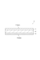
- FIG. 1 is a schematic cross-sectional view showing a base film according to an embodiment of the present disclosure.
- FIG. 1 is a schematic cross-sectional view showing a gas barrier film according to an embodiment of the present disclosure.
- FIG. 1 is a schematic cross-sectional view showing a laminate according to an embodiment of the present disclosure.
- FIG. 1 is a schematic cross-sectional view showing a laminate according to an embodiment of the present disclosure.
- the substrate film is a film (base film) that serves as a support in the gas barrier film, and contains polypropylene.
- the substrate film has a deposition layer containing an inorganic oxide formed on a first surface, which is one of the surfaces.
- the substrate film includes a second skin layer having a second surface, which is the surface opposite to the first surface, and a core layer, and the second skin layer contains silicon-containing particles in a ratio of 1500 ppm by mass to 4000 ppm by mass.
- the substrate film may further include a first skin layer having the first surface.
- the gas barrier film having a deposition layer formed on the first surface of the above-mentioned base film has a second skin layer that satisfies the above-mentioned conditions, and is therefore capable of suppressing flavor deterioration of the contents after retort processing, and of maintaining good oxygen barrier properties even after retort processing.
- FIG. 1 is a schematic cross-sectional view showing a substrate film according to one embodiment.
- the substrate film shown in FIG. 1 has a three-layer structure of a first skin layer 11 having a first surface F1, a core layer 12, and a second skin layer 13 having a second surface F2.
- the substrate film may have a two-layer structure of the second skin layer 13 and the core layer 12, or may have a multi-layer structure of four or more layers that further includes layers other than the first skin layer 11, the core layer 12, and the second skin layer 13.
- the second skin layer 13 contains silicon-containing particles.
- the silicon-containing particles include silica particles and silicate particles.
- the silicate particles include aluminum silicate and calcium silicate.
- the silicon-containing particles may be an antiblocking agent.
- the shape of the silicon-containing particles is not particularly limited, but it is preferable that the silicon-containing particles are spherical or approximately spherical in order to prevent the first skin layer 11, which is in contact with the silicon-containing particles during winding, from the viewpoint of preventing scratches.
- the silicon-containing particles may be used alone or in combination of two or more types.
- the second skin layer 13 preferably contains polypropylene.
- the second skin layer 13 may contain homopolypropylene or a copolymer of propylene and another monomer.
- the second skin layer 13 may contain a copolymer of propylene and an ⁇ -olefin.
- the copolymer may be a random copolymer.
- the melting point of the resin used in the second skin layer 13 may be 130 to 150°C.
- the content of propylene units in the copolymer may be 80 mol% or more, 90 mol% or more, 95 mol% or more, or 96 mol% or more, and may be 99.7 mol% or less, 99.5 mol% or less, 99 mol% or less, or 98 mol% or less, based on the total amount of monomer units.
- the polypropylene used in the second skin layer 13 may be a resin polymerized from fossil fuels, may be a recycled resin, or may be a resin obtained by polymerizing raw materials derived from biomass such as plants. When using these resins, they may be used alone or in combination with a resin polymerized from fossil fuels and a recycled resin or a resin obtained by polymerizing raw materials derived from biomass such as plants.
- the second skin layer 13 contains silicon-containing particles at a ratio of 1500 to 4000 ppm by mass.
- the content of silicon-containing particles in the second skin layer 13 is 1500 ppm by mass or more, good anti-blocking effect and good odor adsorption effect due to the silicon-containing particles can be obtained. This makes it possible to suppress flavor deterioration of the contents even when the contents are placed in a packaging bag and subjected to retort treatment.
- the content of silicon-containing particles in the second skin layer 13 is 4000 ppm by mass or less, it is possible to suppress the falling off of the silicon-containing particles and the occurrence of scratches due to the silicon-containing particles during the production of the gas barrier film.
- the content of silicon-containing particles in the second skin layer 13 is preferably 1500 to 3500 ppm by mass, and more preferably 2000 to 3500 ppm by mass.
- the average particle diameter of the silicon-containing particles is preferably 1 to 6 ⁇ m.
- the average particle diameter is the weight average diameter measured by the coal tar method.
- the average particle diameter of the silicon-containing particles is 1 ⁇ m or more, good anti-blocking effect and good odor adsorption effect can be obtained by the silicon-containing particles. This makes it possible to suppress the deterioration of the flavor of the contents even when the contents are placed in a packaging bag and subjected to retort treatment.
- the average particle diameter of the silicon-containing particles is 6 ⁇ m or less, it is possible to suppress the falling off of the silicon-containing particles and the occurrence of scratches due to the silicon-containing particles during the production of the gas barrier film.
- the average particle diameter of the silicon-containing particles is 2 to 5 ⁇ m.
- the second skin layer 13 may contain an antiblocking agent (hereinafter also referred to as "AB agent") other than silicon-containing particles.
- the other AB agent may be organic particles or inorganic particles. Examples of organic particles include acrylic resin particles, polymethyl methacrylate particles, polystyrene particles, polyamide particles, etc. Among these, it is preferable to use acrylic resin particles or polymethyl methacrylate particles from the viewpoint of minimizing damage to the resin surface by the particles. Any one of these AB agents may be used alone, or two or more types may be used in combination.
- the average particle diameter of the organic particles is preferably 1 to 6 ⁇ m.
- the average particle diameter of the organic particles is 1 ⁇ m or more, a good anti-blocking effect can be obtained by the organic particles.
- the average particle diameter of the organic particles is 6 ⁇ m or less, it is possible to prevent the organic particles from falling off or the organic particles from causing scratches during the production of the gas barrier film. This makes it possible to prevent deterioration of the oxygen barrier property of the gas barrier film, and the gas barrier film can have good oxygen barrier property even after retort treatment. From the viewpoint of obtaining the above effect more fully, it is more preferable that the average particle diameter of the organic particles is 2 to 5 ⁇ m.
- the content is preferably such that the total content of the silicon-containing particles and the other AB agents is 2000 to 4500 ppm by mass, 2000 to 4000 ppm by mass, or 2500 to 4000 ppm by mass.
- the second skin layer 13 may contain, for example, an antioxidant, a stabilizer, a lubricant, an antistatic agent, etc.
- the thickness of the second skin layer 13 is preferably 0.1 to 2.0 ⁇ m, and more preferably 0.3 to 1.5 ⁇ m, from the viewpoint of enabling uniform film formation.
- the first skin layer 11 preferably contains polypropylene.
- the first skin layer 11 may contain homopolypropylene or a copolymer of propylene and another monomer.
- the polypropylene may be the same as that used for the second skin layer 13.
- the first skin layer 11 may contain a copolymer of propylene and an ⁇ -olefin. This improves adhesion between the first skin layer 11 and the core layer 12, and between the first skin layer 11 and the deposition layer.
- ⁇ -olefins include ethylene, 1-butene, and 1-hexene.
- the ⁇ -olefins may be used alone or in combination of two or more.
- the copolymer may be a random copolymer.
- the melting point of the resin used in the first skin layer 11 may be 130 to 150°C.
- the polypropylene used in the first skin layer 11 may be a resin polymerized from fossil fuels, may be a recycled resin, or may be a resin obtained by polymerizing raw materials derived from biomass such as plants. When using these resins, they may be used alone or in combination with a resin polymerized from fossil fuels and a recycled resin or a resin obtained by polymerizing raw materials derived from biomass such as plants.
- the first skin layer 11 may or may not contain an AB agent.
- the first skin layer 11 containing an AB agent can improve the adhesion between the gas barrier film and the outer layer film.
- the AB agent may be silicon-containing particles or other AB agents.
- the other AB agents may be organic particles or inorganic particles. Examples of organic particles include acrylic resin particles, polymethyl methacrylate particles, polystyrene particles, polyamide particles, etc. Among these, it is preferable to use acrylic resin particles or polymethyl methacrylate particles from the viewpoint of less damage to the resin surface by the particles. Any one of these AB agents may be used alone, or two or more may be used in combination.
- the AB agent When the AB agent is a silicon-containing particle, its average particle diameter may be similar to the average particle diameter of the silicon-containing particle used in the second skin layer 13 from the same viewpoint as the second skin layer 13.
- the AB agent When the AB agent is an organic particle, its average particle diameter may be similar to the average particle diameter of the organic particle used in the second skin layer 13 from the same viewpoint as the second skin layer 13.
- the content of the AB agent in the first skin layer 11 may be 1500 ppm by mass or less, or 1000 ppm by mass or less, since good gas barrier properties can be obtained. Furthermore, the content of the AB agent in the first skin layer 11 may be 100 ppm by mass or more, 200 ppm by mass or more, or 250 ppm by mass or more, from the viewpoint of preventing blocking during deposition layer formation. In other words, the content of the AB agent in the first skin layer 11 may be 100 to 1500 ppm by mass, 200 to 1500 ppm by mass, or 250 to 1000 ppm by mass.
- the content of the antiblocking agent in the second skin layer 13 may be 1.0 times or more, or 1.2 times or more, the content of the antiblocking agent in the first skin layer 11.
- the first skin layer 11 may contain, for example, an antioxidant, a stabilizer, a lubricant, an antistatic agent, etc.
- the thickness of the first skin layer 11 is preferably 0.1 to 2.0 ⁇ m, and more preferably 0.3 to 1.5 ⁇ m, from the viewpoint of enabling uniform film formation.
- the core layer 12 preferably contains polypropylene.
- the polypropylene used in the core layer 12 may be crystalline polypropylene, and from the viewpoint of further improving the heat resistance for heat sterilization treatment, it may be homopolypropylene, which is a homopolymer of propylene.
- a random copolymer of propylene and an ⁇ -olefin, or a mixture of the copolymer and homopolypropylene, etc. may also be used.
- the polypropylene used in the core layer 12 may be a resin polymerized from fossil fuels, may be a recycled resin, or may be a resin obtained by polymerizing raw materials derived from biomass such as plants. When using these resins, they may be used alone or in combination with a resin polymerized from fossil fuels and a recycled resin or a resin obtained by polymerizing raw materials derived from biomass such as plants.
- the core layer 12 disposed between the first skin layer 11 and the second skin layer 13 does not need to contain an AB agent.
- the thickness of the core layer 12 may be 10 to 200 ⁇ m, 12 to 50 ⁇ m, or 15 to 30 ⁇ m, depending on the ease of handling when made into a packaging bag.
- the ratio of the thickness of the first skin layer 11 to the thickness of the core layer 12 may be 1/100 to 1/5, or 1/70 to 1/10.
- the thickness ratio is within the above range, the heat resistance of the entire base film 1 can be more sufficiently ensured, and the adhesion between the layers in the gas barrier film and the laminate can be further improved.
- the ratio of the thickness of the second skin layer 13 to the thickness of the core layer 12 may be 1/100 to 1/5, or 1/70 to 1/10.
- the thickness ratio is within the above range, the heat resistance of the entire base film 1 can be more sufficiently ensured, and the adhesion between the layers in the gas barrier film and the laminate can be further improved.
- the first skin layer 11 and the second skin layer 13 can be formed on the core layer 12, for example, by co-extruding a material for forming the core layer 12 with a material for forming the first skin layer 11 and the second skin layer 13.
- the multilayer film may be stretched by conventional means to form a uniaxially or biaxially oriented film.
- a first skin layer 11 is provided on one side of the core layer 12, and a second skin layer 13 is provided on the other side. Both surfaces of the base film 1 may be formed by the first skin layer 11 and the second skin layer 13. Between the core layer 12 and the first skin layer 11, a layer other than the two may be provided, but the core layer 12 and the first skin layer 11 may be in contact with each other without an intervening layer. Between the core layer 12 and the second skin layer 13, a layer other than the two may be provided, but the core layer 12 and the second skin layer 13 may be in contact with each other without an intervening layer.
- the polypropylene content in the base film 1 may be 90% by mass or more, 95% by mass or more, or 99% by mass or more, based on the total mass of the base film.
- the polypropylene content may be substantially 100% by mass (an embodiment in which the base film is made of polypropylene), based on the total mass of the base film.
- the thickness (total thickness) of the base film is not particularly limited, but may be, for example, 10 ⁇ m or more and 200 ⁇ m or less, 12 ⁇ m or more and 50 ⁇ m or less, or 15 ⁇ m or more and 30 ⁇ m or less.
- the substrate film may have an arithmetic mean height Sa1 of the surface (first face F1) facing the first skin layer of the substrate film of 30 nm or more and 80 nm or less, and an arithmetic mean height Sa2 of the surface (second face F2) facing the second skin layer of the substrate film of 40 nm or more and 120 nm or less.
- the first skin layer may contain a copolymer of propylene and an ⁇ -olefin.
- the first skin layer may be the outermost layer on one side of the substrate film, and the second skin layer may be the outermost layer on the other side of the substrate film.
- gas barrier films are manufactured by forming at least a gas barrier vapor deposition layer on a base film, but there is a problem that blocking is likely to occur when the base film on which the vapor deposition layer is formed is wound into a roll.
- One method for suppressing the occurrence of blocking is to use a base film with an uneven surface, but when a gas barrier film using such a base film is subjected to a heat sterilization treatment such as retort treatment, there is a problem that the gas barrier properties are likely to decrease.
- gas barrier films are laminated with other resin films containing polypropylene, such as a sealant layer, and used as packaging materials. Therefore, gas barrier films are required to have good adhesion to other resin films, even when they are subjected to a heat sterilization treatment such as retort treatment after being laminated with other resin films.
- the above-mentioned base film in which the first skin layer contains a copolymer of propylene and an ⁇ -olefin and satisfies the above conditions Sa1 and Sa2, has a first skin layer containing a copolymer of propylene and an ⁇ -olefin and having an arithmetic mean height Sa1 of 30 nm to 80 nm as one of the outermost layers, so that when a vapor deposition layer is formed on the first skin layer to produce a gas barrier film, even if the gas barrier film is subjected to a retort treatment, the adhesion between the first skin layer and the vapor deposition layer is good and defects such as cracks in the vapor deposition layer can be suppressed, resulting in good gas barrier properties.
- the arithmetic mean height Sa2 of the surface on the side opposite to the first skin layer (the second skin layer side) is 40 nm to 120 nm, so that blocking can be suppressed when a vapor deposition layer is formed on the first skin layer and then wound into a roll. Furthermore, by having the arithmetic mean heights Sa1 and Sa2 of both surfaces of the substrate film be within the above ranges, even if a gas barrier film is produced and then laminated with another resin film and then subjected to a retort treatment, good adhesion with the other resin film can be obtained.
- the value of Sa1 may be 30 nm or more and 80 nm or less, but may be 40 nm or more and 80 nm or less from the viewpoint that when a gas barrier film is produced, the gas barrier properties and adhesion to other resin films after retort treatment are further improved, and blocking resistance is further improved.
- the value of Sa2 may be 40 nm or more and 120 nm or less, but may be 45 nm or more and 110 nm or less from the viewpoint that when a gas barrier film is produced, the gas barrier properties and adhesion to other resin films after retort treatment are further improved, and blocking resistance is further improved.
- the total value of Sa1 and Sa2 is not particularly limited, but may be 80 nm or more and 150 nm or less, or 85 nm or more and 145 nm or less, from the viewpoint of further improving the gas barrier properties and adhesion to other resin films after retort treatment and further improving blocking resistance when a gas barrier film is produced.
- the arithmetic mean height (Sa) is a parameter that indicates the surface roughness of the base film, and means the average height of the irregularities on the base film surface.
- the arithmetic mean heights Sa1 and Sa2 of both surfaces of the base film can be measured using a three-dimensional non-contact surface shape measurement system under the condition of a measurement area of 210 ⁇ m square.
- the arithmetic mean heights Sa1 and Sa2 of the base film can be adjusted by changing the type of resin used in the first skin layer 11 and the second skin layer 13, the compounding ratio and melting point differences between multiple resins when multiple resins are used, the addition of an antiblocking agent and its compounding amount, the roll surface state during extrusion, the conditions of stretching after film formation, etc.
- the resins used homopolymers are hard because of their high crystallinity, and are less likely to block even if they are highly smooth, but tend to have poor adhesion.
- copolymers are soft resins that tend to improve adhesion, but tend to be prone to blocking even if they are less smooth.
- the gas barrier film according to this embodiment includes the above-mentioned base film 1 and a vapor deposition layer containing an inorganic oxide arranged on the first surface F1 of the base film 1.
- the gas barrier film according to this embodiment may further include a gas barrier coating layer arranged on the surface of the vapor deposition layer opposite to the base film 1.
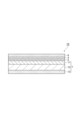
- FIG. 2 is a schematic cross-sectional view showing a gas barrier film according to one embodiment.
- the gas barrier film 10 according to this embodiment comprises, in this order, a base film 1, an anchor coat layer 2, a deposition layer 3, and a gas barrier coating layer 4.
- the anchor coat layer 2 is disposed on the surface of the base film 1 facing the first skin layer 11. Note that the gas barrier film does not necessarily have to comprise the anchor coat layer 2.
- the anchor coat layer 2 is a layer for further improving the adhesion between the base film 1 and the vapor deposition layer 3, and is provided between the base film 1 and the vapor deposition layer 3.
- a material for the anchor coat layer 2 for example, a material containing a reaction product between a polyol compound containing a (meth)acrylic resin and an isocyanate compound can be used.
- (meth)acrylic resin means at least one of "acrylic resin” and the corresponding "methacrylic resin”.
- the (meth)acrylic resin may be, for example, a (meth)acrylic polymer obtained by polymerizing a polymerizable monomer including a (meth)acrylic monomer.
- the (meth)acrylic polymer may be a homopolymer or a copolymer with a polymerizable monomer other than a (meth)acrylic monomer.
- the (meth)acrylic resin may be a resin capable of thermal crosslinking such as urethane curing or epoxy curing.
- the (meth)acrylic resin may be a polyol having two or more hydroxyl groups in one molecule, and in particular may be a (meth)acrylic polyol.
- the (meth)acrylic polyol may be a (meth)acrylic copolymer obtained by copolymerizing a hydrocarbon-based (meth)acrylate with a hydroxyl group-containing monomer, or a (meth)acrylic copolymer obtained by copolymerizing a hydrocarbon-based (meth)acrylate with a hydroxyl group-containing monomer and a monomer component other than these (other monomer component). By copolymerizing the above monomers, a (meth)acrylic polyol containing multiple hydroxyl groups can be obtained.
- the anchor coat layer 2 may contain a curing agent.
- the curing agent may be an isocyanate compound having two or more NCO groups in the molecule, from the viewpoint of excellent reactivity with the (meth)acrylic resin.
- the isocyanate compound may be a monomeric isocyanate.
- monomeric isocyanates include aromatic or araliphatic isocyanates such as tolylene diisocyanate (TDI), diphenylmethane diisocyanate (MDI), xylene diisocyanate (XDI), and tetramethylxylylene diisocyanate (TMXDI); and aliphatic isocyanates such as hexamethylene diisocyanate (HDI), bisisocyanate methylcyclohexane (H6XDI), isophorone diisocyanate (IPDI), and dicyclohexylmethane diisocyanate (H12MDI).
- TDI tolylene diisocyanate
- MDI diphenylmethane diisocyanate
- XDI xylene diisocyanate
- TMXDI tetramethylxylylene diisocyanate
- HDI he
- the isocyanate compound may be a polymer or derivative of the above-mentioned monomeric isocyanate.
- the isocyanate compound may be, for example, an isocyanate having a structure such as a trimer nurate type, an adduct type reacted with 1,1,1-trimethylolpropane, or a biuret type reacted with biuret.
- the isocyanate compound may be an isocyanate having an aromatic ring from the viewpoint of excellent reactivity with the (meth)acrylic resin.
- the content of the isocyanate compound may be an amount such that the number of OH groups in the acrylic polyol is equal to the number of NCO groups in the isocyanate compound.
- the anchor coat layer 2 may contain a silane coupling agent in order to further improve adhesion with the deposition layer 3.
- silane coupling agents include epoxy-based silane coupling agents having an epoxy group, such as 3-glycidoxypropyltrimethoxysilane; amino-based silane coupling agents having an amino group, such as 3-aminopropyltrimethoxysilane; mercapto-based silane coupling agents having a mercapto group, such as 3-mercaptopropyltrimethoxysilane; and isocyanate-based silane coupling agents having an NCO group, such as 3-isocyanatepropyltriethoxysilane. These silane coupling agents can be used alone or in combination of two or more.
- a polyurethane resin formed from an acid group-containing polyurethane and a polyamine can also be used as a material constituting the anchor coat layer 2.
- the polyurethane resin is obtained by bonding the acid groups of the acid group-containing polyurethane with the amino groups of a polyamine as a crosslinking agent.
- the polyurethane resin can be said to be a reaction product of the acid group-containing polyurethane and the polyamine, or to be formed by crosslinking the acid group-containing polyurethane with the polyamine.
- the bond between the acid group of the acid group-containing polyurethane and the amino group of the polyamine may be an ionic bond (e.g., an ionic bond between a carboxyl group and a tertiary amino group) or a covalent bond (e.g., an amide bond, etc.).
- an ionic bond e.g., an ionic bond between a carboxyl group and a tertiary amino group
- a covalent bond e.g., an amide bond, etc.
- a silane coupling agent or a carbodiimide compound may also be added to the polyurethane resin. By adding such a compound, a cross-linked structure is formed with the polyurethane resin, and the gas barrier properties or the adhesion between the substrate film 1 and the deposition layer 3 can be further improved.
- the silane coupling agent any commonly used agent can be used, and examples thereof include compounds in which an alkoxy group and an organic reactive group are bonded to a silicon atom.
- the thickness of the anchor coat layer 2 is not particularly limited as long as it is capable of improving the adhesion between the base film 1 and the deposition layer 3, but is preferably 30 nm or more. In this case, it is possible to further improve the smoothness of the surface of the anchor coat layer 2, make the thickness of the deposition layer 3 more uniform, and further improve the oxygen barrier property, compared to when the thickness of the anchor coat layer 2 is less than 30 nm. This makes it possible to further improve the oxygen barrier property of the gas barrier film 10.
- the thickness of the anchor coat layer 2 is more preferably 40 nm or more, and even more preferably 50 nm or more. By increasing the thickness of the anchor coat layer 2, it is possible to further suppress the deterioration of the gas barrier property when an external force such as stretching is applied.
- the thickness of the anchor coat layer 2 is preferably 2000 nm (2 ⁇ m) or less. In this case, the flexibility of the gas barrier film 10 is improved and the oxygen gas barrier properties of the gas barrier film 10 after abuse can be improved more than when the thickness of the anchor coat layer 2 exceeds 2000 nm. It is more preferable that the thickness of the anchor coat layer 2 is 1500 nm (1.5 ⁇ m) or less.
- the anchor coat layer 2 can be formed, for example, by applying an anchor coat solution onto the resin layer using a method such as gravure coating, roll coating, or bar coating, and then drying it.
- the surface of the base film 1 on which the deposition layer 3 is to be formed may be subjected to a surface treatment such as plasma treatment or corona treatment.
- the anchor coat layer 2 may be provided on the surface that has been subjected to the surface treatment.
- the vapor-deposited layer 3 contains an inorganic oxide. From the viewpoint of improving the gas barrier property against water vapor, oxygen, etc., the vapor-deposited layer 3 may be formed directly on the anchor coat layer 2. The vapor-deposited layer 3 may be transparent.
- the inorganic oxide for example, aluminum oxide, silicon oxide, tin oxide, magnesium oxide, and mixtures thereof can be used. From the viewpoint of excellent resistance to sterilization, the inorganic oxide may be at least one selected from aluminum oxide and silicon oxide.
- the thickness of the deposition layer 3 may be 5 nm or more, 10 nm or more, or 15 nm or more from the viewpoint of a uniform film thickness and excellent gas barrier properties, and may be 300 nm or less, 150 nm or less, or 100 nm or less from the viewpoint of preventing cracks from occurring in the deposition layer 3 even when an external force is applied after film formation. From these viewpoints, the thickness of the deposition layer 3 may be 5 to 300 nm, 10 to 150 nm, or 15 to 100 nm.
- the deposition layer 3 can be formed by, for example, a vacuum deposition method, a plasma-assisted method, an ion-beam-assisted method, a sputtering method, a reactive deposition method, or the like.
- the deposition layer 3 may be formed by a vacuum deposition method from the viewpoint of excellent productivity, or may be formed by a plasma-assisted method or an ion-beam-assisted method from the viewpoint of excellent adhesion between the deposition layer 3 and the base film 1 and from the viewpoint of improving the density of the deposition layer 3, or may be formed by a reactive deposition method in which various gases such as oxygen are blown in from the viewpoint of excellent transparency of the deposition film.
- the heating means for the vacuum deposition method may be an electron beam heating method, a resistance heating method, an induction heating method, etc.
- the heating means for the vacuum deposition method may be an electron beam heating method, because it has a wide range of evaporation material options.
- the gas barrier film 10 may further include a gas barrier coating layer 4 on the opposite side of the deposition layer 3 to the anchor coat layer 2. By including the gas barrier coating layer 4, the gas barrier film 10 can protect the deposition layer 3 and further improve the gas barrier properties.
- the gas barrier coating layer 4 may contain a silicon compound or a hydrolyzate thereof, and a water-soluble polymer having a hydroxyl group.
- the gas barrier coating layer 4 may also contain a water-soluble polymer having a hydroxyl group, and at least one selected from the group consisting of a metal alkoxide, a silane coupling agent, and hydrolyzates thereof.
- the silicon compound may be, for example, at least one selected from Si(OR 1 ) 4 and R 2 Si(OR 3 ) 3.
- OR 1 and OR 3 are each independently a hydrolyzable group, and R 2 is an organic functional group. Examples of R 2 include a vinyl group, an epoxy group, a methacryloxy group, a ureido group, and an isocyanate group.
- Si(OR 1 ) 4 may be tetraethoxysilane (Si(OC 2 H 5 ) 4 ) from the viewpoint of being relatively stable in an aqueous solvent after hydrolysis.
- water-soluble polymers having hydroxyl groups examples include polyvinyl alcohol, polyvinylpyrrolidone, starch, methyl cellulose, carboxymethyl cellulose, sodium alginate, etc.
- the water-soluble polymer having hydroxyl groups may be polyvinyl alcohol from the viewpoint of excellent gas barrier properties.
- the metal alkoxide may be a compound represented by the following general formula (1).
- M(OR 11 ) m (R 12 ) nm ...(1) R 11 and R 12 are each independently a monovalent organic group having 1 to 8 carbon atoms, and are preferably an alkyl group such as a methyl group or an ethyl group.
- M represents an n-valent metal atom such as Si, Ti, Al, or Zr.
- m is an integer from 1 to n.
- the R 11s or the R 12s may be the same or different.
- metal alkoxides include tetraethoxysilane [Si(OC 2 H 5 ) 4 ], triisopropoxyaluminum [Al(O-2′-C 3 H 7 ) 3 ], etc. Tetraethoxysilane and triisopropoxyaluminum are preferred because they are relatively stable in aqueous solvents after hydrolysis.
- the silane coupling agent includes a compound represented by the following general formula (2). Si(OR 21 ) p (R 22 ) 3-p R 23 ...(2)
- R 21 represents an alkyl group such as a methyl group or an ethyl group
- R 22 represents a monovalent organic group such as an alkyl group, an aralkyl group, an aryl group, an alkenyl group, an alkyl group substituted with an acryloxy group, or an alkyl group substituted with a methacryloxy group
- R 23 represents a monovalent organic functional group
- p represents an integer of 1 to 3.
- R 21 or R 22 may be the same or different.
- Examples of the monovalent organic functional group represented by R 23 include a monovalent organic functional group containing a glycidyloxy group, an epoxy group, a mercapto group, a hydroxyl group, an amino group, an alkyl group substituted with a halogen atom, or an isocyanate group.
- a monovalent organic functional group containing a glycidyloxy group, an epoxy group, a mercapto group, a hydroxyl group, an amino group, an alkyl group substituted with a halogen atom, or an isocyanate group may also be used.
- silane coupling agents include vinyltrimethoxysilane, ⁇ -chloropropylmethyldimethoxysilane, ⁇ -chloropropyltrimethoxysilane, 3-glycidoxypropylmethyldimethoxysilane, 3-glycidoxypropyltrimethoxysilane, 3-glycidoxypropylmethyldiethoxysilane, 3-glycidoxypropylmethyltriethoxysilane, ⁇ -methacryloxypropyltrimethoxysilane, ⁇ -methacryloxypropylmethyldimethoxysilane, and other silane coupling agents.
- the gas barrier coating layer 4 may further contain additives such as an isocyanate compound, a silane coupling agent, a dispersant, a stabilizer, a viscosity adjuster, and a colorant.
- additives such as an isocyanate compound, a silane coupling agent, a dispersant, a stabilizer, a viscosity adjuster, and a colorant.
- the thickness of the gas barrier coating layer 4 may be 0.1 ⁇ m or more, or 0.3 ⁇ m or more, and may be 5 ⁇ m or less, or 1 ⁇ m or less.
- the thickness of the gas barrier coating layer 4 may be 0.1 to 5 ⁇ m, or 0.3 to 1 ⁇ m.
- the gas barrier coating layer 4 can be formed, for example, by dissolving a water-soluble polymer in water or a water/alcohol mixed solvent, mixing with a silicon compound or its hydrolysate, a metal alkoxide, a silane coupling agent, etc., and applying this mixed solution onto the deposition layer by a method such as gravure coating, roll coating, or bar coating, and then drying.
- the content of polyvinyl alcohol in the mixed solution may be 20% by mass or more or 25% by mass or more based on the total solid content of the mixed solution from the viewpoint of facilitating the formation of a gas barrier coating layer, and may be 50% by mass or less or 40% by mass or less from the viewpoint of excellent gas barrier properties.
- the content of polyvinyl alcohol in the mixed solution may be 20 to 50% by mass or 25 to 40% by mass based on the total solid content of the mixed solution.
- the laminate according to this embodiment includes the gas barrier film 10 described above, and a sealant layer disposed on the surface of the gas barrier film 10 facing the second skin layer 13.
- the laminate according to this embodiment may further include a second base film containing polypropylene disposed on the surface of the gas barrier film 10 opposite the sealant layer.
- FIG. 3 is a schematic cross-sectional view showing a laminate according to one embodiment.
- the laminate 20 shown in FIG. 3 has a structure in which a sealant layer 23 is laminated on the second skin layer 13 of a gas barrier film 10 via an adhesive layer 24.
- Figure 4 is a schematic cross-sectional view showing a laminate according to another embodiment.
- the laminate 30 shown in Figure 4 has a structure in which a sealant layer 23 is laminated on the second skin layer 13 of the gas barrier film 10 via an adhesive layer 24, and a resin film 22 containing polypropylene as a second base film is laminated on the gas barrier coating layer 4 of the gas barrier film 10 via an adhesive layer 24.
- stretched or unstretched polypropylene film may be used as the sealant layer 23, or unstretched polypropylene film may be used.
- polypropylene as the material for the sealant layer 23, the laminate 20 can be a mono-material packaging material.
- the thickness of the sealant layer 23 is not particularly limited, but may be, for example, 10 ⁇ m or more or 20 ⁇ m or more, and 200 ⁇ m or less or 100 ⁇ m or less.
- the thickness of the sealant layer 23 may be 10 to 200 ⁇ m or 20 to 100 ⁇ m.
- the adhesive layer 24 bonds the films together.
- adhesives that make up the adhesive layer include polyurethane resins in which a bifunctional or higher isocyanate compound is reacted with a base material such as polyester polyol, polyether polyol, acrylic polyol, or carbonate polyol.
- the various polyols may be used alone or in combination of two or more.
- the adhesive layer 24 may contain a carbodiimide compound, an oxazoline compound, an epoxy compound, a phosphorus compound, a silane coupling agent, etc. in addition to the polyurethane resin described above.
- the coating amount of the adhesive layer may be, for example, 0.5 to 10 g/ m2 from the viewpoint of obtaining the desired adhesive strength, followability, processability, etc.
- the adhesive layer may be made of a polymer component derived from biomass or biodegradable from the viewpoint of environmental consideration. Also, an adhesive having barrier properties may be used for the adhesive layer.
- the resin film 22 may be laminated onto the gas barrier coating layer 4 of the gas barrier film 10 via the adhesive layer 24.
- a film of stretched homopolypropylene may be used to provide heat resistance.
- the thickness of the resin film 22 is not particularly limited, but may be, for example, 3 ⁇ m or more and 200 ⁇ m or less, or 6 ⁇ m or more and 50 ⁇ m or less.
- the packaging material can be produced using the above-mentioned laminate. If the laminate uses the above-mentioned gas barrier film, a packaging material having a sufficiently low oxygen permeability and excellent lamination strength can be produced even after heat sterilization such as retort treatment. In addition, if the laminate uses the above-mentioned gas barrier film, a packaging material capable of suppressing flavor deterioration of the contents even after heat sterilization such as retort treatment can be produced. Therefore, a packaging material produced from such a laminate can contain food, beverages, medicines, etc., and is particularly suitable for containing food and beverages.
- the laminate may be made into a bag-shaped packaging material (packaging bag) by folding one laminate in half so that the sealant layers face each other, and then heat-sealing the three sides other than the folded part, or may be made into a bag-shaped packaging material (packaging bag) by stacking two laminates so that the sealant layers face each other, and then heat-sealing the four sides.
- the packaging material may be equipped with a stopper.
- a packaging material with a stopper may be fixed by sandwiching the stopper between the two laminated sheets that form the packaging material, or a hole may be drilled in one side of the packaging material and the spout may be glued and fixed.
- the spout may be provided on the top surface of the packaging material, or on the side, bottom, or diagonally upward of the packaging material. If the contents are liquid or gel-like, in addition to the spout plug (known as a spout), a straw that reaches the bottom of the packaging material may be provided so that the contents can be directly put to the mouth and sucked out.
- Another form of packaging material with a spout is a bag-in-box in which a bag (inner bag) for containing liquids such as soft drinks or alcoholic beverages is placed in a carton (outer box).
- the laminate according to this embodiment can be used for the bag-in-box bag, particularly for a bag equipped with a spout (tube) for pouring.
- the stopper portion and the entire stopper of the cap may be made of the same resin as the base film of the gas barrier film, from the viewpoint of improving recyclability.
- the anchor coat layer forming composition was prepared as follows. ⁇ -isocyanate propyl trimethoxysilane and acrylic polyol were added into ethyl acetate as a dilution solvent, mixed, and stirred. At this time, the acrylic polyol was added at a ratio of 5 parts by mass per 1 part by mass of ⁇ -isocyanate propyl trimethoxysilane. As the acrylic polyol, GS-5756 (trade name) manufactured by Mitsubishi Rayon Co., Ltd. was used.
- tolylene diisocyanate (TDI) was added as an isocyanate compound so that the amount of NCO groups was equal to the amount of OH groups of the acrylic polyol.
- the obtained mixed solution was diluted with the dilution solvent to obtain an anchor coat layer forming composition having a solid content concentration of 2% by mass.
- composition for forming gas barrier coating layer ⁇ Preparation of composition for forming gas barrier coating layer> The following raw material solutions A, B, and C were mixed in a mass ratio of 0.5:0.4:0.1 to prepare a composition for forming a gas barrier coating layer.
- Raw material solutions A, B, and C were mixed in a mass ratio of 0.5:0.4:0.1 to prepare a composition for forming a gas barrier coating layer.
- (Raw material solution A) Polyvinyl alcohol (trade name "Kuraray Poval 60-98", manufactured by Kuraray Co., Ltd.) was dissolved in water to a solid content of 5% by mass.
- TEOS Tetraethoxysilane
- methanol manufactured by Kanto Chemical Co., Ltd.
- 0.1 N hydrochloric acid manufactured by Kanto Chemical Co., Ltd.
- Example 1 (Preparation of Base Film) First, a 1000 ⁇ m thick laminated film having a three-layer structure of a first skin layer/core layer/second skin layer was produced by melt extruding the materials of each layer with a screw extruder. At this time, homopolypropylene was used as the material of the core layer, and an ethylene-propylene random copolymer (hereinafter referred to as "copolymerized PP (1)") with a melting point of 132°C was used as the material of the first skin layer and the second skin layer. Synthetic silica particles (average particle size 5 ⁇ m) were added as an antiblocking agent (AB agent) to the second skin layer to the content shown in Table 1.
- AB agent antiblocking agent
- the laminated film was stretched 5 times in the machine direction (MD) and 10 times in the transverse direction (TD) using a tenter, and the surface on the first skin layer side was subjected to a corona treatment to obtain a simultaneously biaxially stretched polypropylene (PP) film with a thickness of 20 ⁇ m as a base film.
- the machine direction is the direction of melt extrusion
- the transverse direction is the direction perpendicular to the direction of melt extrusion.
- the first skin layer had a thickness of 1 ⁇ m
- the core layer had a thickness of 18 ⁇ m
- the second skin layer had a thickness of 1 ⁇ m.
- the surface on the first skin layer side of the base film is the first surface on which the deposition layer is formed
- the surface on the second skin layer side is the second surface.
- the composition for forming an anchor coat layer prepared as described above was applied to the first surface of the substrate film using a bar coater so that the thickness after drying was 0.2 ⁇ m, and the coating was dried at 60 ° C for 1 minute to form an anchor coat layer.
- an alumina deposition layer having a thickness of 20 nm was formed on the anchor coat layer using a vacuum deposition device.
- the composition for forming a gas barrier coating layer prepared as described above was applied to the surface of the deposition layer using a bar coater so that the thickness after drying was 0.3 ⁇ m, and the coating layer was dried in an oven at 50 ° C for 1 minute to form a gas barrier coating layer. This resulted in a gas barrier film.
- Example 2 A gas barrier film was produced in the same manner as in Example 1, except that the average particle diameter of the synthetic silica particles added to the second skin layer was changed as shown in Table 1, and polymethyl methacrylate (PMMA) particles (average particle diameter 2 ⁇ m) were further added to the second skin layer as an AB agent to the content shown in Table 1.
- PMMA polymethyl methacrylate
- Example 3 A gas barrier film was produced in the same manner as in Example 1, except that the content of synthetic silica particles in the second skin layer was changed as shown in Table 1, and PMMA particles (average particle diameter 4 ⁇ m) as an AB agent were further added to the second skin layer to the content shown in Table 1.
- Example 4 A gas barrier film was produced in the same manner as in Example 1, except that an ethylene-1-butene-1-propylene random copolymer having a melting point of 148°C (hereinafter referred to as "copolymer PP (2)") was used as the material for the first skin layer and the second skin layer.
- copolymer PP (2) an ethylene-1-butene-1-propylene random copolymer having a melting point of 148°C
- Example 5 A gas barrier film was produced in the same manner as in Example 1, except that the average particle size and content of the synthetic silica particles in the second skin layer were changed as shown in Table 1.
- Example 2 A gas barrier film was produced in the same manner as in Example 1, except that copolymer PP (2) was used as the material for the first skin layer and the second skin layer, the average particle size and content of the synthetic silica particles in the second skin layer were changed as shown in Table 1, and PMMA particles (average particle size 4 ⁇ m) were further added to the second skin layer as an AB agent to achieve the content shown in Table 1.
- a gas barrier film was prepared in the same manner as in Example 1, except that no synthetic silica particles were added to the second skin layer, and instead PMMA particles (average particle size 4 ⁇ m) were added to the second skin layer at the content shown in Table 1.
- Examples 6 to 10 and Comparative Examples 5 to 8 The gas barrier films of Examples 6 to 10 and Comparative Examples 5 to 8 were produced in the same manner as in Examples 1 to 5 and Comparative Examples 1 to 4, except that synthetic silica particles (average particle size 2 ⁇ m) were added as an AB agent to the first skin layer in the amounts shown in Table 2.
- Examples 11 to 15 and Comparative Examples 9 to 12 The gas barrier films of Examples 11 to 15 and Comparative Examples 9 to 12 were produced in the same manner as in Examples 1 to 5 and Comparative Examples 1 to 4, except that acrylic resin particles (average particle size: 2 ⁇ m) were added as an AB agent to the first skin layer in the amounts shown in Table 3.
- ⁇ Measurement of arithmetic mean height Sa> The arithmetic mean height Sa1 of the surface on the first skin layer side and the arithmetic mean height Sa2 of the surface on the second skin layer side of the substrate films produced in the Examples and Comparative Examples were measured using a three-dimensional non-contact surface shape measurement system (VertScan R3300h Lite, manufactured by Ryoka Systems Co., Ltd.) under the condition of a measurement area of 210 ⁇ m square. The results are shown in Tables 1 to 3.
- Laminate A A 60 ⁇ m-thick unstretched polypropylene film was bonded as a sealant layer to the side (second side) opposite the gas barrier coating layer (second skin layer side) of the gas barrier films produced in the Examples and Comparative Examples by dry lamination using a two-component curing urethane adhesive, to produce a laminate A consisting of a gas barrier coating layer/vapor deposition layer/anchor coat layer/first skin layer/core layer/second skin layer/adhesive layer/sealant layer.
- Laminate B The surface (first surface) of the gas barrier film prepared in the Examples and Comparative Examples on the side of the gas barrier coating layer was bonded to a biaxially oriented polypropylene film (OPP) having a thickness of 20 ⁇ m as a resin film by a dry lamination method via a two-component curing urethane adhesive.
- OPP biaxially oriented polypropylene film
- the surface (second surface) of the gas barrier film on the side of the second skin layer was bonded to a non-oriented polypropylene film (CPP) having a thickness of 60 ⁇ m as a sealant layer by a dry lamination method via a two-component curing urethane adhesive to prepare a laminate B consisting of a resin film (OPP)/gas barrier coating layer/vapor deposition layer/anchor coat layer/first skin layer/core layer/second skin layer/adhesive layer/sealant layer (CPP).
- a resin film (OPP)/gas barrier coating layer/vapor deposition layer/anchor coat layer/first skin layer/core layer/second skin layer/adhesive layer/sealant layer CPP
- the peel strength was measured using a Tensilon universal material testing machine (manufactured by A & D Co., Ltd., RTC-1250). This peel strength was used as an index of the blocking resistance of the substrate film, and was evaluated based on the following evaluation criteria. The results are shown in Tables 1 to 3. If the result is "A", it can be said that the substrate film has excellent blocking resistance.
- B Peel strength is 0.5N/150mm or more.
- ⁇ Making packaging bags> A sheet of A4 size (297 mm long side x 210 mm short side) was cut out from the laminate A prepared above. The sheet was folded in half so that the short sides of both ends overlapped, and the overlapping long sides were heat-sealed to prepare a packaging bag (pouch) with an opening. Next, 150 g of boiled chicken mince meat (containing 700 mg of amino acids per 100 g) was filled into the packaging bag as the contents, and the opening was heat-sealed to seal it. The sealed packaging bag was subjected to a retort treatment to obtain a packaging bag after retort treatment. The retort treatment (retort sterilization) was performed by holding at 120°C for 30 minutes using a hot water storage retort kettle.
- the packaging bag after retort sterilization was opened, and a part (100 mm x 100 mm) of the laminate A was cut out as an evaluation sample.
- the oxygen transmission rate (OTR) of the cut out sample was measured under conditions of 30°C and 70% RH using an oxygen transmission rate measuring device (product name "OX-TRAN2/20", manufactured by Modern Control). This measured value was used as an index of the oxygen barrier property of the laminate A.
- OTR measurement was performed in accordance with JIS K7126-2. The OTR results are shown in Tables 1 to 3.
- Adhesion strength after retort treatment A packaging bag with four sealed sides was prepared using the laminate B, and water was filled as the content. Then, a retort sterilization treatment was performed at 130° C. for 30 minutes. The laminate B that had been subjected to the retort sterilization treatment was cut into a size of 150 mm wide x 500 mm long, and the adhesion strength was measured. The adhesion strength was measured by measuring the adhesion strength between the biaxially oriented polypropylene film (OPP) and the first skin layer, and the adhesion strength between the second skin layer and the unoriented polypropylene film (CPP). The results are shown in Tables 1 to 3.
- OPP biaxially oriented polypropylene film
- CPP unoriented polypropylene film
Landscapes
- Laminated Bodies (AREA)
- Wrappers (AREA)
Priority Applications (4)
| Application Number | Priority Date | Filing Date | Title |
|---|---|---|---|
| JP2025504487A JP7761178B2 (ja) | 2023-05-18 | 2024-05-15 | ガスバリア性フィルム、積層体及び包装袋 |
| EP24807239.9A EP4706960A1 (en) | 2023-05-18 | 2024-05-15 | Gas barrier film, laminate, and packaging bag |
| CN202480012015.1A CN120677064A (zh) | 2023-05-18 | 2024-05-15 | 阻气性膜、层叠体以及包装袋 |
| JP2025171976A JP2025185134A (ja) | 2023-05-18 | 2025-10-10 | ガスバリア性フィルム、積層体及び包装袋 |
Applications Claiming Priority (4)
| Application Number | Priority Date | Filing Date | Title |
|---|---|---|---|
| JP2023082102 | 2023-05-18 | ||
| JP2023-082102 | 2023-05-18 | ||
| JP2023214215 | 2023-12-19 | ||
| JP2023-214215 | 2023-12-19 |
Publications (1)
| Publication Number | Publication Date |
|---|---|
| WO2024237288A1 true WO2024237288A1 (ja) | 2024-11-21 |
Family
ID=93519726
Family Applications (1)
| Application Number | Title | Priority Date | Filing Date |
|---|---|---|---|
| PCT/JP2024/017992 Ceased WO2024237288A1 (ja) | 2023-05-18 | 2024-05-15 | ガスバリア性フィルム、積層体及び包装袋 |
Country Status (4)
| Country | Link |
|---|---|
| EP (1) | EP4706960A1 (https=) |
| JP (2) | JP7761178B2 (https=) |
| CN (1) | CN120677064A (https=) |
| WO (1) | WO2024237288A1 (https=) |
Cited By (1)
| Publication number | Priority date | Publication date | Assignee | Title |
|---|---|---|---|---|
| JP7789873B1 (ja) * | 2024-10-04 | 2025-12-22 | 王子ホールディングス株式会社 | ポリプロピレンフィルム、包装材料、及び包装体 |
Citations (7)
| Publication number | Priority date | Publication date | Assignee | Title |
|---|---|---|---|---|
| JP2020011413A (ja) * | 2018-07-17 | 2020-01-23 | 凸版印刷株式会社 | 積層体およびパウチ |
| WO2020116544A1 (ja) * | 2018-12-05 | 2020-06-11 | 凸版印刷株式会社 | ガスバリア性フィルム |
| JP2020168834A (ja) * | 2019-04-05 | 2020-10-15 | 凸版印刷株式会社 | ガスバリア性フィルム |
| WO2021230319A1 (ja) * | 2020-05-14 | 2021-11-18 | 凸版印刷株式会社 | ガスバリアフィルム |
| WO2022004340A1 (ja) * | 2020-07-03 | 2022-01-06 | 東洋紡株式会社 | 二軸配向ポリプロピレン系フィルム |
| WO2022019192A1 (ja) * | 2020-07-21 | 2022-01-27 | 東洋紡株式会社 | 積層フィルム |
| JP2023050299A (ja) | 2021-09-30 | 2023-04-11 | 凸版印刷株式会社 | ガスバリア性積層体、包装フィルム、包装容器及び包装製品 |
Family Cites Families (1)
| Publication number | Priority date | Publication date | Assignee | Title |
|---|---|---|---|---|
| JP2023077283A (ja) | 2021-11-24 | 2023-06-05 | 大日本印刷株式会社 | バリア性基材、バリア性積層体及び包装容器 |
-
2024
- 2024-05-15 EP EP24807239.9A patent/EP4706960A1/en active Pending
- 2024-05-15 CN CN202480012015.1A patent/CN120677064A/zh active Pending
- 2024-05-15 JP JP2025504487A patent/JP7761178B2/ja active Active
- 2024-05-15 WO PCT/JP2024/017992 patent/WO2024237288A1/ja not_active Ceased
-
2025
- 2025-10-10 JP JP2025171976A patent/JP2025185134A/ja active Pending
Patent Citations (7)
| Publication number | Priority date | Publication date | Assignee | Title |
|---|---|---|---|---|
| JP2020011413A (ja) * | 2018-07-17 | 2020-01-23 | 凸版印刷株式会社 | 積層体およびパウチ |
| WO2020116544A1 (ja) * | 2018-12-05 | 2020-06-11 | 凸版印刷株式会社 | ガスバリア性フィルム |
| JP2020168834A (ja) * | 2019-04-05 | 2020-10-15 | 凸版印刷株式会社 | ガスバリア性フィルム |
| WO2021230319A1 (ja) * | 2020-05-14 | 2021-11-18 | 凸版印刷株式会社 | ガスバリアフィルム |
| WO2022004340A1 (ja) * | 2020-07-03 | 2022-01-06 | 東洋紡株式会社 | 二軸配向ポリプロピレン系フィルム |
| WO2022019192A1 (ja) * | 2020-07-21 | 2022-01-27 | 東洋紡株式会社 | 積層フィルム |
| JP2023050299A (ja) | 2021-09-30 | 2023-04-11 | 凸版印刷株式会社 | ガスバリア性積層体、包装フィルム、包装容器及び包装製品 |
Cited By (2)
| Publication number | Priority date | Publication date | Assignee | Title |
|---|---|---|---|---|
| JP7789873B1 (ja) * | 2024-10-04 | 2025-12-22 | 王子ホールディングス株式会社 | ポリプロピレンフィルム、包装材料、及び包装体 |
| WO2026074980A1 (ja) * | 2024-10-04 | 2026-04-09 | 王子ホールディングス株式会社 | ポリプロピレンフィルム、包装材料、及び包装体 |
Also Published As
| Publication number | Publication date |
|---|---|
| JPWO2024237288A1 (https=) | 2024-11-21 |
| CN120677064A (zh) | 2025-09-19 |
| JP2025185134A (ja) | 2025-12-18 |
| EP4706960A1 (en) | 2026-03-11 |
| JP7761178B2 (ja) | 2025-10-28 |
Similar Documents
| Publication | Publication Date | Title |
|---|---|---|
| US20230053232A1 (en) | Gas barrier film | |
| EP4245534A1 (en) | Laminate, packaging bag, and standing pouch | |
| JP7377425B2 (ja) | バリアフィルム、積層体及び包装袋 | |
| WO2021112243A1 (ja) | ガスバリアフィルム | |
| JP7677515B2 (ja) | ガスバリア積層体 | |
| US20240278546A1 (en) | Gas barrier film and packaging material | |
| JP7848924B2 (ja) | 包装材料、包装体及び包装物品 | |
| JP7786252B2 (ja) | 包装材料 | |
| JP2025185134A (ja) | ガスバリア性フィルム、積層体及び包装袋 | |
| JP2024096178A (ja) | ガスバリアフィルム | |
| US20260084878A1 (en) | Packaging film, packaging container, and packaged product | |
| WO2024096024A1 (ja) | 共押出多層フィルム、積層体及び包装袋 | |
| JP2021091202A (ja) | ガスバリアフィルム | |
| JP7786251B2 (ja) | 包装材料 | |
| WO2024101161A1 (ja) | ガスバリアフィルム、包装フィルム、包装袋、及び包装製品 | |
| JP2022159102A (ja) | ガスバリアフィルム、積層体および包装袋 | |
| EP4691759A1 (en) | Barrier film, layered body, packaging container, and packaging product | |
| CN118265610A (zh) | 阻隔膜、层叠体以及包装袋 | |
| JP2025104871A (ja) | 基材フィルム、ガスバリア性フィルム、積層体及び包装袋 | |
| JP2025175964A (ja) | ガスバリア性フィルム、積層体及び包装袋 | |
| JP2021109381A (ja) | ガスバリアフィルム、これを用いた積層体およびガスバリアフィルムの製造方法 | |
| JP7830375B2 (ja) | スタンディングパウチ及び包装物品 | |
| JP7736214B2 (ja) | 積層体及びそれを用いた包装製品 | |
| JP7838723B1 (ja) | 積層体及び包装材料 | |
| JP2024058265A (ja) | ガスバリア性フィルム用積層体、ガスバリア性フィルム、包装フィルム、包装容器及び包装製品 |
Legal Events
| Date | Code | Title | Description |
|---|---|---|---|
| 121 | Ep: the epo has been informed by wipo that ep was designated in this application |
Ref document number: 24807239 Country of ref document: EP Kind code of ref document: A1 |
|
| WWE | Wipo information: entry into national phase |
Ref document number: 2025504487 Country of ref document: JP |
|
| WWE | Wipo information: entry into national phase |
Ref document number: 202480012015.1 Country of ref document: CN |
|
| WWP | Wipo information: published in national office |
Ref document number: 202480012015.1 Country of ref document: CN |
|
| WWE | Wipo information: entry into national phase |
Ref document number: 2024807239 Country of ref document: EP |
|
| WWE | Wipo information: entry into national phase |
Ref document number: 202547123428 Country of ref document: IN |
|
| ENP | Entry into the national phase |
Ref document number: 2024807239 Country of ref document: EP Effective date: 20251205 |
|
| NENP | Non-entry into the national phase |
Ref country code: DE |
|
| ENP | Entry into the national phase |
Ref document number: 2024807239 Country of ref document: EP Effective date: 20251205 |
|
| ENP | Entry into the national phase |
Ref document number: 2024807239 Country of ref document: EP Effective date: 20251205 |
|
| ENP | Entry into the national phase |
Ref document number: 2024807239 Country of ref document: EP Effective date: 20251205 |
|
| ENP | Entry into the national phase |
Ref document number: 2024807239 Country of ref document: EP Effective date: 20251205 |
|
| ENP | Entry into the national phase |
Ref document number: 2024807239 Country of ref document: EP Effective date: 20251205 |
|
| ENP | Entry into the national phase |
Ref document number: 2024807239 Country of ref document: EP Effective date: 20251205 |
|
| ENP | Entry into the national phase |
Ref document number: 2024807239 Country of ref document: EP Effective date: 20251205 |
|
| WWP | Wipo information: published in national office |
Ref document number: 2024807239 Country of ref document: EP |