WO2024224874A1 - 溶接状態の検出方法及び検出装置 - Google Patents
溶接状態の検出方法及び検出装置 Download PDFInfo
- Publication number
- WO2024224874A1 WO2024224874A1 PCT/JP2024/010417 JP2024010417W WO2024224874A1 WO 2024224874 A1 WO2024224874 A1 WO 2024224874A1 JP 2024010417 W JP2024010417 W JP 2024010417W WO 2024224874 A1 WO2024224874 A1 WO 2024224874A1
- Authority
- WO
- WIPO (PCT)
- Prior art keywords
- signal strength
- signal intensity
- detecting
- reference signal
- welding
- Prior art date
- Legal status (The legal status is an assumption and is not a legal conclusion. Google has not performed a legal analysis and makes no representation as to the accuracy of the status listed.)
- Ceased
Links
Images





Classifications
-
- G—PHYSICS
- G01—MEASURING; TESTING
- G01N—INVESTIGATING OR ANALYSING MATERIALS BY DETERMINING THEIR CHEMICAL OR PHYSICAL PROPERTIES
- G01N21/00—Investigating or analysing materials by the use of optical means, i.e. using sub-millimetre waves, infrared, visible or ultraviolet light
- G01N21/62—Systems in which the material investigated is excited whereby it emits light or causes a change in wavelength of the incident light
- G01N21/71—Systems in which the material investigated is excited whereby it emits light or causes a change in wavelength of the incident light thermally excited
-
- B—PERFORMING OPERATIONS; TRANSPORTING
- B23—MACHINE TOOLS; METAL-WORKING NOT OTHERWISE PROVIDED FOR
- B23K—SOLDERING OR UNSOLDERING; WELDING; CLADDING OR PLATING BY SOLDERING OR WELDING; CUTTING BY APPLYING HEAT LOCALLY, e.g. FLAME CUTTING; WORKING BY LASER BEAM
- B23K26/00—Working by laser beam, e.g. welding, cutting or boring
- B23K26/02—Positioning or observing the workpiece, e.g. with respect to the point of impact; Aligning, aiming or focusing the laser beam
- B23K26/03—Observing, e.g. monitoring, the workpiece
- B23K26/032—Observing, e.g. monitoring, the workpiece using optical means
-
- B—PERFORMING OPERATIONS; TRANSPORTING
- B23—MACHINE TOOLS; METAL-WORKING NOT OTHERWISE PROVIDED FOR
- B23K—SOLDERING OR UNSOLDERING; WELDING; CLADDING OR PLATING BY SOLDERING OR WELDING; CUTTING BY APPLYING HEAT LOCALLY, e.g. FLAME CUTTING; WORKING BY LASER BEAM
- B23K26/00—Working by laser beam, e.g. welding, cutting or boring
-
- B—PERFORMING OPERATIONS; TRANSPORTING
- B23—MACHINE TOOLS; METAL-WORKING NOT OTHERWISE PROVIDED FOR
- B23K—SOLDERING OR UNSOLDERING; WELDING; CLADDING OR PLATING BY SOLDERING OR WELDING; CUTTING BY APPLYING HEAT LOCALLY, e.g. FLAME CUTTING; WORKING BY LASER BEAM
- B23K26/00—Working by laser beam, e.g. welding, cutting or boring
- B23K26/20—Bonding
- B23K26/21—Bonding by welding
-
- B—PERFORMING OPERATIONS; TRANSPORTING
- B23—MACHINE TOOLS; METAL-WORKING NOT OTHERWISE PROVIDED FOR
- B23K—SOLDERING OR UNSOLDERING; WELDING; CLADDING OR PLATING BY SOLDERING OR WELDING; CUTTING BY APPLYING HEAT LOCALLY, e.g. FLAME CUTTING; WORKING BY LASER BEAM
- B23K26/00—Working by laser beam, e.g. welding, cutting or boring
- B23K26/20—Bonding
- B23K26/21—Bonding by welding
- B23K26/24—Seam welding
- B23K26/244—Overlap seam welding
-
- B—PERFORMING OPERATIONS; TRANSPORTING
- B23—MACHINE TOOLS; METAL-WORKING NOT OTHERWISE PROVIDED FOR
- B23K—SOLDERING OR UNSOLDERING; WELDING; CLADDING OR PLATING BY SOLDERING OR WELDING; CUTTING BY APPLYING HEAT LOCALLY, e.g. FLAME CUTTING; WORKING BY LASER BEAM
- B23K31/00—Processes relevant to this subclass, specially adapted for particular articles or purposes, but not covered by any single one of main groups B23K1/00 - B23K28/00
- B23K31/12—Processes relevant to this subclass, specially adapted for particular articles or purposes, but not covered by any single one of main groups B23K1/00 - B23K28/00 relating to investigating the properties, e.g. the weldability, of materials
- B23K31/125—Weld quality monitoring
-
- G—PHYSICS
- G01—MEASURING; TESTING
- G01N—INVESTIGATING OR ANALYSING MATERIALS BY DETERMINING THEIR CHEMICAL OR PHYSICAL PROPERTIES
- G01N21/00—Investigating or analysing materials by the use of optical means, i.e. using sub-millimetre waves, infrared, visible or ultraviolet light
- G01N21/84—Systems specially adapted for particular applications
- G01N21/88—Investigating the presence of flaws or contamination
- G01N21/95—Investigating the presence of flaws or contamination characterised by the material or shape of the object to be examined
-
- G—PHYSICS
- G01—MEASURING; TESTING
- G01N—INVESTIGATING OR ANALYSING MATERIALS BY DETERMINING THEIR CHEMICAL OR PHYSICAL PROPERTIES
- G01N33/00—Investigating or analysing materials by specific methods not covered by groups G01N1/00 - G01N31/00
- G01N33/20—Metals
- G01N33/207—Welded or soldered joints; Solderability
-
- G—PHYSICS
- G01—MEASURING; TESTING
- G01N—INVESTIGATING OR ANALYSING MATERIALS BY DETERMINING THEIR CHEMICAL OR PHYSICAL PROPERTIES
- G01N21/00—Investigating or analysing materials by the use of optical means, i.e. using sub-millimetre waves, infrared, visible or ultraviolet light
- G01N21/17—Systems in which incident light is modified in accordance with the properties of the material investigated
- G01N21/55—Specular reflectivity
-
- G—PHYSICS
- G01—MEASURING; TESTING
- G01N—INVESTIGATING OR ANALYSING MATERIALS BY DETERMINING THEIR CHEMICAL OR PHYSICAL PROPERTIES
- G01N21/00—Investigating or analysing materials by the use of optical means, i.e. using sub-millimetre waves, infrared, visible or ultraviolet light
- G01N21/84—Systems specially adapted for particular applications
- G01N21/88—Investigating the presence of flaws or contamination
- G01N21/8806—Specially adapted optical and illumination features
Definitions
- This disclosure relates to a method and device for detecting a welding condition.
- Patent Document 1 discloses a method for detecting the welding state.
- the detection method described in Patent Document 1 includes a step of detecting reflected light from the portion irradiated with the laser and emitted light in the portion irradiated with the laser, and a step of detecting the welding state of the portion irradiated with the laser based on the detected reflected light and the detected emitted light.
- the step of detecting the welding state it is detected whether the signal level of the emitted light is equal to or higher than a predetermined first threshold and whether the signal level of the reflected light is equal to or lower than a predetermined second threshold.
- a method for detecting a welding condition includes: 1.
- a method for detecting a welding condition executed by a processor comprising: acquiring a first signal intensity indicating an intensity of thermal radiation light generated from a portion irradiated with a laser, and a second signal intensity indicating an intensity of reflected light reflected from the portion irradiated with the laser; detecting a welding state of the portion irradiated with the laser based on the first signal intensity and the second signal intensity; Including, The step of detecting the welding condition includes determining whether the first signal strength is smaller than or equal to a first reference signal strength of thermal radiation light and whether the second signal strength is greater than a second reference signal strength of reflected light.
- a welding condition detection device includes: A processor; a memory device storing instructions for execution by the processor; Equipped with The instruction: acquiring a first signal intensity indicating an intensity of thermal radiation light generated from a portion irradiated with a laser, and a second signal intensity indicating an intensity of light reflected from the portion irradiated with the laser; Detecting a welding state of the portion irradiated with the laser based on the first signal intensity and the second signal intensity; Including, The step of detecting the welding condition includes determining whether the first signal strength is smaller than or equal to a first reference signal strength of thermal radiation light and whether the second signal strength is greater than a second reference signal strength of reflected light.
- FIG. 1 is a schematic diagram for explaining an example of the mechanism of a dent caused by laser welding.
- FIG. 1 is a schematic diagram for explaining an example of the mechanism of a dent caused by laser welding.
- FIG. 1 is a schematic diagram for explaining an example of the mechanism of a dent caused by laser welding.
- FIG. 1 is a schematic block diagram showing an example of a configuration of a laser processing system including a detection device according to a first embodiment of the present disclosure.
- FIG. 9 is a schematic enlarged view of a portion Z1 of FIG. 8 .
- Graph showing an example of signal intensity of reflected light 1 is a flowchart showing an example of a process for generating a first reference signal intensity of thermal radiation light and determining a first threshold value.
- 1 is a flowchart showing an example of a process for generating a second reference signal intensity of reflected light and determining a second threshold value.
- a welding defect may occur due to the material of the object.
- One type of welding defect is a dent in the solidified part after melting. The occurrence of a dent not only impairs the appearance, but may also cause a lack of strength in the joint joined by welding. Furthermore, depending on the severity of the dent, it may progress to a hole.
- the method described in Patent Document 1 detects dents caused by the scattering of molten metal that occurs during laser welding by detecting a decrease in the signal level of reflected light from the area irradiated with the laser and an increase in the signal level of light emitted from the laser irradiated area. In this way, the method described in Patent Document 1 determines that a dent has occurred in the area irradiated with the laser.
- the mechanism by which dents are formed by laser welding differs depending on the process, such as the welding method and welding materials.
- the method described in Patent Document 1 may not be able to detect the welding condition depending on the welding method and welding materials.
- the detection method described in Patent Document 1 cannot detect the welding condition.
- the inventors therefore discovered a configuration that can detect the welding state when welding a metal plate to multiple metal plates, leading to the present disclosure.
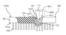
- Fig. 1 is a schematic diagram for explaining the concept of the present disclosure.
- Fig. 1 shows a state in which an object 100 is laser welded.
- the object 100 to be welded by the laser L1 has a first metal plate 101 and a number of second metal plates 102.
- the first metal plate 101 is a plate having a first surface 101a and a second surface 101b opposite the first surface 101a.
- the second metal plate 102 is a metal that is thinner than the first metal plate 101, and is, for example, a metal foil.
- the multiple second metal plates 102 are disposed on the first surface 101a of the first metal plate 101.
- the multiple second metal plates 102 are in contact with the first surface 101a of the first metal plate 101.
- the multiple second metal plates 102 are arranged at intervals in a direction perpendicular to the normal direction of the first surface 101a of the first metal plate 101. In this embodiment, the multiple second metal plates 102 are arranged at equal intervals in a direction perpendicular to the normal direction of the first surface 101a of the first metal plate 101.
- the multiple second metal plates 102 each extend in a direction intersecting the first surface 101a of the first metal plate 101.
- the multiple second metal plates 102 each extend in a direction perpendicular to the first surface 101a of the first metal plate 101.
- a laser L1 is irradiated onto the second surface 101b of the first metal plate 101.
- the laser L1 is irradiated onto the second surface 101b of the first metal plate 101 while being scanned in the direction in which the multiple second metal plates 102 are arranged.
- the portion irradiated with the laser L1 becomes hot, forming a molten portion 110.
- the molten portion 110 is a portion in which the metal is in a molten state.
- the temperature of the molten portion 110 drops, and the molten portion 110 becomes a solidified portion 112.
- the solidified portion 112 is a portion in which the molten metal has solidified.
- reflected light RL1 of the laser L1 is generated in the direction in which the laser L1 is irradiated.
- the reflected light RL1 is light that is reflected by the molten surface 111 of the molten part 110.
- thermal radiation light HL1 is also generated from the molten surface 111 in the direction in which the laser L1 is irradiated.
- the thermal radiation light HL1 is light that is radiated from the molten surface 111 of the molten part 110, which has become hot due to the irradiation of the laser L1.
- the intensity of the reflected light RL1 changes depending on the state of the molten surface 111 of the molten part 110, and the intensity of the thermal radiation light HL1 changes depending on the temperature of the molten surface 111.
- the melting state detection method and detection device disclosed herein measures the signal strength of the thermal radiation light HL1 and reflected light RL1 detected within the measurement range MS1, and detects dents that occur during welding based on changes in the two signal strengths.
- Figures 2A to 2C show schematic diagrams to explain an example of the mechanism of dents that occur due to laser welding.
- FIG. 2A shows a state in which a gap 113 occurs between the first metal plate 101 and the multiple second metal plates 102. As shown in FIG. 2A, when there is a gap 113 between the first metal plate 101 and the multiple second metal plates 102, the molten part 110 moves into the space of the gap 113.
- FIG. 2B shows the appearance of a dent on the molten surface 111.
- the movement of the molten part 110 toward the gap 113 progresses, and a dent begins to form on the molten surface 111 of the molten part 110.
- the heat of the molten part 110 moves to the second metal plate 102 due to the difference in thermal conductivity between the molten part 110 and the second metal plate 102.
- the temperature of the molten part 110 drops, and a cooling part 114 is formed.
- the cooling part 104 is the part of the molten part 110 where the temperature has dropped.
- the intensity of the thermal radiation light HL1 generated from the molten surface 111 drops.
- Figure 2C shows how the depression in the molten part 110 progresses.
- the inclination of the molten surface 111 changes, and the direction in which the reflected light RL1 is reflected is altered.
- the reflected light RL1 begins to reflect in a direction approximately parallel to the irradiation direction of the laser L1.
- specular reflected light begins to return to the area where the reflected light RL1 is detected.
- the intensity of the reflected light RL1 detected within the measurement range MS1 increases.
- the welding condition can be detected based on the decrease in intensity of the thermal radiation light HL1 and the increase in intensity of the reflected light RL1.
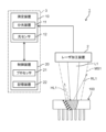
- FIG. 3 is a schematic block diagram showing an example of the configuration of a laser processing system 1 including a detection device 3 according to the first embodiment of the present disclosure.
- the laser processing system 1 includes a laser processing device 2 and a detection device 3.
- the laser processing device 2 is a device that performs laser welding by irradiating a laser L1 onto an object 100.
- the laser processing device 2 is disposed above the object 100 at a predetermined distance. The predetermined distance is set so that the spot diameter of the laser L1 on the surface of the object 100 is an appropriate size for welding.
- the laser processing device 2 also guides to a detection device 3 thermal radiation light HL1 and reflected light RL1 generated at a portion of the object 100 irradiated with the laser L1.
- FIG. 4 is a schematic diagram showing an example of the configuration of the laser processing device 2.
- the laser processing device 2 includes a laser oscillator 30, lenses 31 to 33, a half mirror 34, and an optical fiber 35.
- the laser oscillator 30 outputs a laser beam L1.
- the laser beam L1 output from the laser oscillator 30 is collimated by a lens 31.
- the collimated laser beam L1 passes through a half mirror 34 and enters a lens 32.
- the laser beam L1 is focused by the lens 32 and irradiated onto the object 100.
- Thermal radiation light HL1 and reflected light RL1 are generated from the portion of the object 100 irradiated with the laser L1.
- the thermal radiation light HL1 and reflected light RL1 are received by the lens 32.
- the optical axis of the thermal radiation light HL1 and reflected light RL1 received by the lens 32 is converted, for example, by 90° by the half mirror 34, and the thermal radiation light HL1 and reflected light RL1 are incident on the lens 33.
- the thermal radiation light HL1 and reflected light RL1 are focused by the lens 33 into the optical fiber 35.
- the optical fiber 35 transmits the thermal radiation light HL1 and reflected light RL1 to the detection device 3.
- the measurement range MS1 is determined by the core diameter of the optical fiber 35 and the focal length of the lenses 32 and 33.
- the configuration of the laser processing device 2 described above is an example and is not limited to the present disclosure.
- the laser processing device 2 may include a galvanometer mirror disposed between the half mirror 34 and the lens 32.
- the laser L1 may be scanned over the target object 100 by the galvanometer mirror.
- the detection device 3 includes a measurement device 10 and a control device 20 .
- the measuring device 10 measures a first signal intensity indicating the intensity of thermal radiation light HL1 generated from the portion irradiated with the laser L1, and a second signal intensity indicating the intensity of reflected light RL1 reflected from the portion irradiated with the laser L1.
- the measurement device 10 includes a spectroscopic device 11 and an optical sensor 12.
- the spectroscopic device 11 separates the light transmitted from the optical fiber 35 into thermal radiation light HL1 and reflected light RL1.
- the spectroscopic device 11 separates the light by wavelength.
- the thermal radiation light HL1 has a wavelength of 1300 nm
- the reflected light RL1 has a wavelength of 515 nm.
- the spectroscopic device 11 includes, for example, a half mirror, a diffraction grating, etc.
- the optical sensor 12 detects the first signal intensity of the thermal radiation light HL1 and the second signal intensity of the reflected light RL1 separated by the spectroscopic device 11.
- the measuring device 10 has two optical sensors 12 for receiving the thermal radiation light HL1 and the reflected light RL1, respectively.
- the two optical sensors are sensitive to the wavelengths of the thermal radiation light HL1 and the reflected light RL1, respectively.
- the optical sensor 12 is an element that outputs a voltage when light is input.
- the optical sensor 12 may be a photodiode, etc.
- the first signal intensity of the thermal radiation light HL1 and the second signal intensity of the reflected light RL1 detected by the optical sensor 12 are transmitted to the control device 20.
- the configuration of the measuring device 10 described above is merely an example and is not limited to this disclosure.
- the control device 20 controls the measuring device 10.
- the control device 20 receives a first signal intensity of the thermal radiation light HL1 and a second signal intensity of the reflected light RL1 from the measuring device 10, and determines the welding condition based on the first signal intensity and the second signal.
- the control device 20 includes a processor 21 and a storage device 22.
- the control device 20 realizes a predetermined function by the processor 21 executing instructions stored in the storage device 22.
- the function of the control device 20 may be configured only by hardware, or may be realized by a combination of hardware and software.
- the control device 20 may include one or more processors 21.
- the processor 21 can be configured, for example, by a microcomputer, a CPU, an MPU, a GPU, a DSU, an FPGA, an ASIC, etc.
- the processor 21 may also be configured by a dedicated electronic circuit designed to realize a specified function.
- the storage device 22 is a storage medium that stores programs and data for implementing the functions of the control device 20.
- the storage device 22 can be implemented, for example, by a hard disk drive (HDD), SSD, RAM, DRAM, ferroelectric memory, flash memory, magnetic disk, or a combination of these.
- control device 20 converts the voltage signal acquired from the measuring device 10 into a digital signal by AD conversion, and processes the signal as waveform data.
- the processed waveform data is stored in the storage device 22.
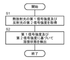
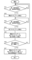
- FIG. 5 is a flowchart showing an example of the process of the detection device 3 according to the first embodiment of the present disclosure.
- FIG. 6 is a flowchart showing an example of the process of detecting the welding state.
- the detection device 3 performs steps S1 and S2.
- step S1 the detection device 3 acquires a first signal intensity indicating the intensity of the thermal radiation light HL1 and a second signal intensity indicating the intensity of the reflected light RL1.
- the spectroscopic device 11 separates the light transmitted from the optical fiber 35 into thermal radiation light HL1 and reflected light RL1.
- the optical sensor 12 receives the separated thermal radiation light HL1 and reflected light RL1, and detects a first signal intensity of the thermal radiation light HL1 and a second signal intensity of the reflected light RL1.
- the detected first signal intensity and second signal intensity are transmitted to the control device 20.
- the control device 20 obtains the first signal intensity and second signal intensity.
- step S2 the detection device 3 detects the welding condition based on the first signal intensity of the thermal radiation light HL1 and the second signal intensity of the reflected light RL1.
- step S2 steps S10 and S20 to S23 shown in FIG. 6 are performed.
- step S10 a detection time region P1 in which the first signal intensity of the thermal radiation light HL1 is equal to or lower than the first reference signal intensity is detected.
- the first reference signal intensity is the reference signal intensity of the thermal radiation light HL1 generated from the molten surface 111 during laser welding, and is the signal intensity of the thermal radiation light HL1 in a normal welding state without any abnormalities such as dents.
- the first reference signal intensity is the signal intensity of the average waveform of the thermal radiation light HL1 in a normal welding state.
- step S10 the detection time region P1 is detected using a first threshold T1 that is smaller than the first reference signal strength. Step S10 will be described in detail below with reference to Figures 7 to 9.
- FIG. 7 is a flow chart showing an example of a process for detecting the detection time region P1.
- FIG. 8 is a graph showing an example of the first signal intensity of the thermal radiation light HL1.
- FIG. 9 is a schematic enlarged view of the Z1 portion of FIG. 8. Note that the graphs shown in FIGS. 8 and 9 show the first signal intensity, first reference signal intensity, and first threshold value T1 of the thermal radiation light HL1 when a depression occurs.
- steps S11 to S16 are performed in the process of detecting detection time region P1.
- step S11 the detection device 3 determines whether the first signal strength is equal to or less than a first threshold T1, which is smaller than the first reference signal strength.
- the first reference signal strength and/or the first threshold T1 are stored, for example, in the storage device 22.
- the detection device 3 determines whether the first signal strength is smaller than or equal to the first threshold T1, which is smaller than the first reference signal strength. If the detection device 3 determines that the first signal strength is greater than the first threshold T1, it repeats step S11. If the detection device 3 determines that the first signal strength is smaller than or equal to the first threshold T1, it performs step S12.
- step S12 the detection device 3 detects a first timing th1 at which the first signal strength becomes smaller than or equal to a first threshold T1.
- step S13 the detection device 3 determines whether the first signal strength is greater than or equal to the first threshold T1 after the first timing th1 . If the detection device 3 determines that the first signal strength is less than the first threshold T1, it repeats step S13. If the detection device 3 determines that the first signal strength is greater than or equal to the first threshold T1, it performs step S14.
- step S14 the detection device 3 detects a second time th2 at which the first signal strength becomes equal to or greater than the first threshold value T1 after the first time th1 .
- step S15 the detection device 3 detects, based on the first timing th1 and the second timing th2 , the start timing t1 at which the first signal strength begins to become smaller than the first reference signal strength, and the end timing t2 at which the first signal strength becomes greater than the first reference signal strength.
- the detection device 3 detects a start timing t1 at which the first signal strength becomes equal to or less than a first reference signal strength, before the first timing th1 .
- a start timing t1 at which the first signal strength becomes equal to or less than a first reference signal strength
- the start timing t1 is the timing that is equal to or less than the first timing th1 and is closest to the first timing th1 .
- the detection device 3 detects an end timing t2 at which the first signal strength becomes equal to or greater than the first reference signal strength after the second timing th2 .
- the end timing t2 is the timing that is equal to or greater than the second timing th2 and is closest to the second timing th2 .
- step S16 the detection device 3 determines the detection time region P1 based on the start timing t1 and the end timing t2.
- step S10 steps S11 to S16 are performed to detect the detection time region P1.
- step S20 the detection device 3 determines whether the second signal intensity of the reflected light RL1 is greater than the second reference signal intensity within the detection time region P1.
- the second reference signal intensity is the reference signal intensity of the reflected light RL1 generated from the molten surface 111 during laser welding, and is the signal intensity of the reflected light RL1 when the welding condition is normal and there are no abnormalities such as dents.
- the second reference signal intensity is the signal intensity of the average waveform of the reflected light RL1 when the welding condition is normal.
- step S20 determines in step S20 that the second signal strength of the reflected light RL1 is greater than the second reference signal strength within the detection time region P1
- the process proceeds to step S21 and determines that there is a dent. If the detection device 3 determines that the second signal strength is equal to or less than the second reference signal strength within the detection time region P1, the process proceeds to step S22 and determines that there is no dent.
- the detection device 3 outputs the determination result.
- the detection device 3 may output a flag indicating whether or not a dent is present.
- the detection device 3 may output information indicating whether or not a dent is present to an output device such as a display.
- step S20 the detection device 3 determines whether or not a dent is present using a second threshold T2 that is greater than the second reference signal strength. Step S20 will be described in detail below with reference to FIG. 10.
- FIG. 10 is a graph showing an example of the signal strength of the reflected light RL1. Note that the graph shown in FIG. 10 shows the second signal strength, the second reference signal strength, and the second threshold value of the reflected light RL1 when a dent occurs.
- the detection device 3 determines whether the second signal intensity of the reflected light RL1 within the detection time region P1 is greater than or equal to a second threshold T2 that is greater than the second reference signal intensity.
- the second reference signal strength and/or the second threshold T2 are stored, for example, in the storage device 22.
- the detection device 3 determines that the second signal strength is greater than or equal to the second threshold T2 within the detection time region P1, it determines that there is a dent. If the detection device 3 determines that the second signal strength is less than the second threshold T2 within the detection time region P1, it determines that there is no dent.
- FIG. 11 is a flowchart showing an example of the process of generating the first reference signal intensity of the thermal radiation light HL1 and determining the first threshold T1.
- the detection device 3 performs steps S31 to S33 to generate a first reference signal strength and determine a first threshold value T1.
- step S31 the detection device 3 acquires N signal waveforms of the thermal radiation light HL1. Specifically, the detection device 3 acquires N signal waveforms of the thermal radiation light HL1 when the welding state is normal.
- N is, for example, 10 or more.
- step S32 the detection device 3 generates a first reference signal intensity indicating an average waveform of the thermal radiation light HL1 from the N signal waveforms. Specifically, the detection device 3 generates the average waveform of the thermal radiation light HL1 by calculating the average of the N signal intensities.
- the detection device 3 determines the first threshold T1 based on the average waveform of the thermal radiation light HL1. For example, the detection device 3 calculates the standard deviation of the average waveform of the thermal radiation light HL1, and determines the lower limit of the standard deviation as the first threshold T1. Alternatively, the detection device 3 may determine the lower limit of the standard deviation of the thermal radiation light HL1 multiplied by k as the first threshold T1. k is an integer greater than or equal to 1 and less than or equal to 5. Preferably, k is 5.
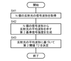
- FIG. 12 is a flowchart showing an example of a process for determining the second threshold T2 of the signal strength of the reflected light RL1.
- the detection device 3 determines the second threshold value T2 by performing steps S41 to S43.
- step S41 the detection device 3 acquires the signal waveforms of the N reflected lights RL1. Specifically, the detection device 3 acquires the signal waveforms of the N reflected lights RL1 when the welding state is normal.
- step S42 the detection device 3 generates a second reference signal intensity indicating the average waveform of the reflected light RL1 from the N signal waveforms. Specifically, the detection device 3 generates the average waveform of the reflected light RL1 by calculating the average of the N signal intensities.
- the detection device 3 determines the second threshold T2 based on the average waveform of the reflected light RL1. For example, the detection device 3 calculates the standard deviation of the average waveform of the reflected light RL1, and determines the upper limit of the standard deviation as the second threshold T2. Alternatively, the detection device 3 may determine the upper limit m times the standard deviation of the reflected light RL1 as the second threshold T2. m is an integer between 1 and 5. Preferably, m is 5.
- first reference signal strength, second reference signal strength, first threshold T1, and second threshold T2 are not limited to the present disclosure.
- the first reference signal strength and the second reference signal strength may be the median value of N signal waveforms.
- the first threshold T1 and the second threshold T2 may be set to any constant.
- the first threshold T1 and the second threshold T2 may be determined based on the maximum value of the N signal waveforms.
- the detection device 3 may use the first signal strength and the second signal strength used in the detection when determining the first reference signal strength, the second reference signal strength, the first threshold value T1, and the second threshold value T2 described above. This makes it possible to update the first reference signal strength, the second reference signal strength, the first threshold value T1, and the second threshold value T2.
- the method for detecting the welding state includes step S1 of acquiring the signal intensities of the thermal radiation light HL1 and the reflected light RL1, and step S2 of detecting the welding state.
- step S1 a first signal intensity indicating the intensity of the thermal radiation light HL1 generated from the portion irradiated with the laser L1 and a second signal intensity indicating the intensity of the reflected light RL1 reflected from the portion irradiated with the laser L1 are acquired.
- step S2 the welding state of the portion irradiated with the laser L1 is detected based on the first signal intensity and the second signal intensity.
- step S2 it is determined whether or not the first signal intensity is smaller than or equal to the first reference signal intensity of the thermal radiation light HL1 and the second signal intensity is larger than the second reference signal intensity of the reflected light RL1.
- the welding state can be detected when welding a metal plate and a plurality of metal plates. For example, when welding a first metal plate 101 having a specified surface and a plurality of second metal plates 102 arranged along a direction perpendicular to the normal direction of the specified surface, the welding condition such as dents in the area irradiated with laser L1 can be detected.
- Step S2 of detecting the welding state includes step S11 of detecting a detection time region P1, and step S12 of determining whether or not the second signal strength is greater than a second reference signal strength within the detection time region P1.
- the detection time region P1 is a time region in which the first signal strength is smaller than or equal to the first reference signal strength.
- Step S11 of detecting the detection time region P1 includes steps S21 to S24 of detecting the first timing th1 and the second timing th2 , step S25 of detecting the start timing t1 and the end timing t2 , and step S26 of determining the detection time region P1.
- the first timing th1 is the timing at which the first signal strength becomes smaller than or equal to a first threshold value T1 that is smaller than a reference signal strength
- the second timing th2 is the timing at which the first signal strength becomes larger than or equal to the first threshold value T1 after the first timing th1 .
- the start timing t1 is the timing at which the first signal strength begins to become smaller than the first reference signal strength
- the end timing t2 is the timing at which the first signal strength becomes larger than the first reference signal strength.
- the start timing t1 and the end timing t2 are detected based on the first timing th1 and the second timing th2 .
- the detection time region P1 is determined based on the start timing t1 and the end timing t2 . With this configuration, the welding state can be detected with high accuracy.
- Step S2 of detecting the welding state includes determining whether the second signal strength is greater than or equal to a second threshold T2 that is greater than the second reference signal strength. With this configuration, the welding state can be detected with higher accuracy.
- the first reference signal intensity is the signal intensity of the average waveform of the thermal radiation light HL1 when the welding condition is normal
- the second reference signal intensity is the signal intensity of the average waveform of the reflected light RL1 when the welding condition is normal.
- the first reference signal strength is the signal strength of the average waveform of the thermal radiation light HL1 in a normal welding state
- the first threshold T1 is determined by a lower limit value obtained by multiplying the standard deviation of the average waveform of the thermal radiation light HL1 by k.
- k is an integer between 1 and 5.
- the second reference signal strength is the signal strength of the average waveform of the reflected light RL1 when the welding condition is normal, and the second threshold T2 is determined by an upper limit value m times the standard deviation of the average waveform of the reflected light RL1.
- m is an integer between 1 and 5. This configuration allows the welding condition to be detected with higher accuracy.
- step S2 of detecting the welding state if it is determined that the first signal strength is equal to or less than the first reference signal strength and the second signal strength is greater than the second reference signal strength, it is determined that a dent is present.
- the detection device 3 also provides the same effects as the detection method described above.
- the detection device 3 includes the measurement device 10
- the present invention is not limited to this.
- the detection device 3 does not need to include the measurement device 10.
- the detection device 3 only needs to include a processor and a storage device 22 that stores instructions to be executed by the processor.
- information on the first signal strength and the second signal strength detected by the measuring device 10 may be stored in a server, and the detecting device 3 may obtain the first signal strength and the second signal strength from the server via a wired or wireless network.
- the detection of the detection time region P1 is performed using the first threshold value T1
- the present invention is not limited to this.
- it is sufficient to detect a time region in which the first signal intensity of the thermal radiation light HL1 is smaller than or equal to the first reference signal intensity, and the detection may be performed without using the first threshold value T1.
- the detection of a dent is performed using the second threshold value T2
- the present invention is not limited to this.
- the detection of a dent may be performed without using the second threshold value T2 as long as it can be determined based on the second signal strength of the reflected light RL1 being greater than the second reference signal strength.
- the detection time region P1 is detected when the state in which the first signal intensity of the thermal radiation light HL1 is smaller than or equal to the first reference signal intensity continues for a predetermined period of time or more.
- FIG. 13 is a flowchart showing another example of the process for detecting the detection time region P1. As shown in FIG. 13, in the first modification, the detection time region P1 is detected by performing steps S51 to S57.
- step S51 the detection device 3 determines whether the first signal strength of the thermal radiation light HL1 is smaller than or equal to the first reference signal strength. If the first signal strength of the thermal radiation light HL1 is smaller than or equal to the first reference signal strength, the detection device 3 performs step S52. If the first signal strength of the thermal radiation light HL1 is greater than the first reference signal strength, the detection device 3 repeats step S51.
- step S52 the detection device 3 detects the start timing t1 at which the first signal intensity of the thermal radiation light HL1 starts to decrease to or below the first reference signal intensity.
- step S53 the detection device 3 determines whether or not the first signal intensity of the thermal radiation light HL1 becomes greater than or equal to the first reference signal intensity after the start timing t1 . If the first signal intensity of the thermal radiation light HL1 becomes greater than or equal to the first reference signal intensity, the detection device 3 performs step S54. If the first signal intensity of the thermal radiation light HL1 is smaller than the first reference signal intensity, the detection device 3 repeats step S53.
- step S54 the detection device 3 detects the end time t2 at which the first signal strength becomes equal to or greater than the first reference signal strength after the start time t1 .
- step S55 the detection device 3 calculates a difference time td between the start timing t1 and the end timing t2 .
- the difference time td is the time from the start timing t1 to the end timing t2 .
- step S56 the detection device 3 determines whether the differential time td is equal to or greater than the third threshold T3.
- the third threshold T3 may be any constant. For example, the third threshold T3 is set to 5 ms or greater. If the differential time td is equal to or greater than the third threshold T3, the detection device 3 performs step S57. If the differential time td is smaller than the third threshold T3, the detection device 3 returns to step S51.
- step S57 the detection device 3 determines a detection time region P1 based on the start timing t1 and the end timing t2 .
- the detection time region P1 is determined by performing steps S51 to S57.
- the detection time region P1 is determined based on whether or not the difference time td is equal to or greater than the third threshold value T3.
- the present invention is not limited to this. For example, when a predetermined time or more has elapsed since the start timing t1 in a state in which the first signal intensity of the thermal radiation light HL1 is reduced to equal to or less than the first reference signal intensity, the detection device 3 may detect the end timing t2 to determine the detection time region P1.
- first, second, etc. are used herein for descriptive purposes only and should not be understood as expressing or implying the relative importance or ranking of technical features.
- Features qualified as “first” and “second” expressly or imply the inclusion of one or more of that feature.
- a detection method of one aspect of the present disclosure is a welding condition detection method executed by a processor, and includes the steps of acquiring a first signal intensity indicating an intensity of thermal radiation light generated from a portion irradiated with a laser and a second signal intensity indicating an intensity of reflected light reflected from the portion irradiated with the laser, and detecting a welding condition of the portion irradiated with the laser based on the first signal intensity and the second signal intensity, wherein the step of detecting the welding condition determines whether the first signal intensity is smaller than or equal to a first reference signal intensity of thermal radiation light and the second signal intensity is greater than a second reference signal intensity of reflected light.
- the step of detecting the welding state may include detecting a detection time region in which the first signal strength is smaller than or equal to the first reference signal strength, and determining whether or not the second signal strength is greater than the second reference signal strength within the detection time region.
- detecting the detection time region may include detecting a first timing at which the first signal strength becomes smaller than or equal to a first threshold value smaller than the first reference signal strength, and a second timing at which the first signal strength becomes larger than or equal to the first threshold value after the first timing, detecting a start timing at which the first signal strength begins to become smaller than the first reference signal strength and an end timing at which the first signal strength becomes larger than the first reference signal strength based on the first timing and the second timing, and determining the detection time region from the start timing and the end timing.
- detecting the detection time region may include detecting the detection time region when the state in which the first signal strength is smaller than or equal to the first reference signal strength continues for a predetermined period of time or more.
- the step of detecting the welding state may include determining whether the second signal strength is greater than or equal to a second threshold value that is greater than the second reference signal strength.
- the first reference signal intensity may be the signal intensity of an average waveform of thermal radiation light in a normal welding state
- the second reference signal intensity may be the signal intensity of an average waveform of reflected light in a normal welding state
- the first reference signal strength may be the signal strength of the average waveform of the thermal radiation light in a normal welding state
- the first threshold value may be determined as a lower limit value obtained by multiplying the standard deviation of the average waveform of the thermal radiation light by k, where k may be an integer between 1 and 5.
- the second reference signal strength may be the signal strength of the average waveform of the reflected light in a normal welding state
- the second threshold may be determined as an upper limit value m times the standard deviation of the average waveform of the reflected light, where m may be an integer between 1 and 5.
- the step of detecting the welding state may determine that a dent is present when it is determined that the first signal strength is equal to or smaller than the first reference signal strength and the second signal strength is greater than the second reference signal strength.
- a detection device includes a processor and a storage device storing instructions executed by the processor, the instructions including: acquiring a first signal intensity indicating the intensity of thermal radiation light generated from a portion irradiated with a laser and a second signal intensity indicating the intensity of reflected light reflected from the portion irradiated with the laser; and detecting a welding state of the portion irradiated with the laser based on the first signal intensity and the second signal intensity, the step of detecting the welding state determining whether the first signal intensity is smaller than or equal to a first reference signal intensity of thermal radiation light and whether the second signal intensity is larger than a second reference signal intensity of reflected light.
- detecting the welding state may include detecting a detection time region in which the first signal strength is smaller than or equal to the first reference signal strength, and determining whether the second signal strength is greater than the second reference signal strength within the detection time region.
- detecting the detection time region may include detecting a first timing at which the first signal strength becomes smaller than or equal to a first threshold value smaller than the first reference signal strength, and a second timing at which the first signal strength becomes larger than or equal to the first threshold value after the first timing, detecting a start timing at which the first signal strength begins to become smaller than the first reference signal strength and an end timing at which the first signal strength becomes larger than the first reference signal strength based on the first timing and the second timing, and determining the detection time region from the start timing and the end timing.
- detecting the detection time region may include detecting the detection time region when a state in which the first signal strength is smaller than or equal to the first reference signal strength continues for a predetermined period of time or more.
- detecting the welding state may include determining whether the second signal strength is greater than or equal to a second threshold value that is greater than the second reference signal strength.
- the first reference signal intensity may be the signal intensity of an average waveform of thermal radiation light in a normal welding state
- the second reference signal intensity may be the signal intensity of an average waveform of reflected light in a normal welding state
- the first reference signal strength may be the signal strength of the average waveform of the thermal radiation light in a normal welding state
- the first threshold may be determined as k times the standard deviation of the average waveform of the thermal radiation light, where k may be an integer between 1 and 5.
- the second reference signal strength may be the signal strength of the average waveform of the reflected light in a normal welding state, and the second threshold may be determined as m times the standard deviation of the average waveform of the reflected light, where m may be an integer between 1 and 5.
- the detection of the welding state may include determining that a dent is present when it is determined that the first signal strength is less than or equal to the first reference signal strength and the second signal strength is greater than the second reference signal strength.
- a program according to one aspect of the present disclosure causes a processor to execute any one of the welding condition detection methods (1) to (9).
- a non-transitory computer-readable storage medium stores a program that causes a processor to execute any one of the welding condition detection methods (1) to (9).
- the present disclosure provides a detection method and detection device capable of detecting the welding state when welding a metal plate to multiple metal plates.
- This disclosure can be applied to a detection device and detection method for the welding condition when welding with a laser.
Landscapes
- Physics & Mathematics (AREA)
- Engineering & Computer Science (AREA)
- Optics & Photonics (AREA)
- Health & Medical Sciences (AREA)
- Chemical & Material Sciences (AREA)
- Life Sciences & Earth Sciences (AREA)
- Mechanical Engineering (AREA)
- Analytical Chemistry (AREA)
- Biochemistry (AREA)
- General Health & Medical Sciences (AREA)
- General Physics & Mathematics (AREA)
- Immunology (AREA)
- Pathology (AREA)
- Plasma & Fusion (AREA)
- Food Science & Technology (AREA)
- Medicinal Chemistry (AREA)
- Nuclear Medicine, Radiotherapy & Molecular Imaging (AREA)
- Quality & Reliability (AREA)
- Laser Beam Processing (AREA)
Priority Applications (3)
| Application Number | Priority Date | Filing Date | Title |
|---|---|---|---|
| JP2025516597A JPWO2024224874A1 (https=) | 2023-04-25 | 2024-03-18 | |
| CN202480025920.0A CN121194849A (zh) | 2023-04-25 | 2024-03-18 | 焊接状态的检测方法以及检测装置 |
| US19/360,896 US20260043745A1 (en) | 2023-04-25 | 2025-10-16 | Method and device for detecting welding state |
Applications Claiming Priority (2)
| Application Number | Priority Date | Filing Date | Title |
|---|---|---|---|
| JP2023-071392 | 2023-04-25 | ||
| JP2023071392 | 2023-04-25 |
Related Child Applications (1)
| Application Number | Title | Priority Date | Filing Date |
|---|---|---|---|
| US19/360,896 Continuation US20260043745A1 (en) | 2023-04-25 | 2025-10-16 | Method and device for detecting welding state |
Publications (1)
| Publication Number | Publication Date |
|---|---|
| WO2024224874A1 true WO2024224874A1 (ja) | 2024-10-31 |
Family
ID=93256168
Family Applications (1)
| Application Number | Title | Priority Date | Filing Date |
|---|---|---|---|
| PCT/JP2024/010417 Ceased WO2024224874A1 (ja) | 2023-04-25 | 2024-03-18 | 溶接状態の検出方法及び検出装置 |
Country Status (4)
| Country | Link |
|---|---|
| US (1) | US20260043745A1 (https=) |
| JP (1) | JPWO2024224874A1 (https=) |
| CN (1) | CN121194849A (https=) |
| WO (1) | WO2024224874A1 (https=) |
Citations (5)
| Publication number | Priority date | Publication date | Assignee | Title |
|---|---|---|---|---|
| JP2000061672A (ja) * | 1998-08-20 | 2000-02-29 | Sumitomo Heavy Ind Ltd | レーザ溶接の溶接状態検出方法 |
| JP2012006036A (ja) * | 2010-06-24 | 2012-01-12 | Nishihara Denshi:Kk | 欠陥電極検出装置 |
| JP2021137867A (ja) * | 2020-03-09 | 2021-09-16 | 株式会社アマダ | レーザ溶接モニタリング装置及びレーザ溶接モニタリング方法 |
| WO2022004610A1 (ja) * | 2020-06-29 | 2022-01-06 | パナソニックIpマネジメント株式会社 | レーザ溶接装置およびレーザ溶接方法 |
| JP2022092729A (ja) * | 2020-12-11 | 2022-06-23 | 株式会社東芝 | 溶接状態の検出方法、および溶接装置 |
-
2024
- 2024-03-18 WO PCT/JP2024/010417 patent/WO2024224874A1/ja not_active Ceased
- 2024-03-18 JP JP2025516597A patent/JPWO2024224874A1/ja active Pending
- 2024-03-18 CN CN202480025920.0A patent/CN121194849A/zh active Pending
-
2025
- 2025-10-16 US US19/360,896 patent/US20260043745A1/en active Pending
Patent Citations (5)
| Publication number | Priority date | Publication date | Assignee | Title |
|---|---|---|---|---|
| JP2000061672A (ja) * | 1998-08-20 | 2000-02-29 | Sumitomo Heavy Ind Ltd | レーザ溶接の溶接状態検出方法 |
| JP2012006036A (ja) * | 2010-06-24 | 2012-01-12 | Nishihara Denshi:Kk | 欠陥電極検出装置 |
| JP2021137867A (ja) * | 2020-03-09 | 2021-09-16 | 株式会社アマダ | レーザ溶接モニタリング装置及びレーザ溶接モニタリング方法 |
| WO2022004610A1 (ja) * | 2020-06-29 | 2022-01-06 | パナソニックIpマネジメント株式会社 | レーザ溶接装置およびレーザ溶接方法 |
| JP2022092729A (ja) * | 2020-12-11 | 2022-06-23 | 株式会社東芝 | 溶接状態の検出方法、および溶接装置 |
Also Published As
| Publication number | Publication date |
|---|---|
| JPWO2024224874A1 (https=) | 2024-10-31 |
| US20260043745A1 (en) | 2026-02-12 |
| CN121194849A (zh) | 2025-12-23 |
Similar Documents
| Publication | Publication Date | Title |
|---|---|---|
| KR101007724B1 (ko) | 레이저 용접 모니터 | |
| JP5570451B2 (ja) | レーザ溶接装置およびレーザ溶接方法 | |
| JP5947740B2 (ja) | 溶接部の検査装置とその検査方法 | |
| JP5911903B2 (ja) | レーザ光の強度分布を計測するビームプロファイラ、レーザ発振器、およびレーザ加工装置 | |
| JP2002516984A (ja) | 構造物の性質を測定する装置及び方法 | |
| EP2796858A1 (en) | Optical non-destructive inspection apparatus and optical non-destructive inspection method | |
| EP3193161B1 (en) | Optical nondestructive testing method and optical nondestructive testing apparatus | |
| CN114535787A (zh) | 激光加工系统以及夹具 | |
| EP2803983A1 (en) | Infrared non-destructive inspection method and apparatus | |
| JPWO2018185973A1 (ja) | レーザ加工監視方法及びレーザ加工監視装置 | |
| JP2013535676A (ja) | 距離測定用装置 | |
| WO2022181359A1 (ja) | レーザ加工状態の判定方法及び判定装置 | |
| WO2024224874A1 (ja) | 溶接状態の検出方法及び検出装置 | |
| EP2796857A1 (en) | Optical non-destructive inspection apparatus and optical non-destructive inspection method | |
| JP2015021791A (ja) | 熱拡散率測定装置 | |
| JP6852008B2 (ja) | 光学検査装置、半導体素子及び光学検査方法 | |
| JP2010223653A (ja) | 構造物の内部状態を測定する測定装置及び測定方法 | |
| JP2010071886A (ja) | レーザ超音波検出装置及びレーザ超音波検出方法 | |
| JP7098956B2 (ja) | 光学非破壊検査方法及び光学非破壊検査装置 | |
| JP5117039B2 (ja) | 膜厚測定方法及び膜厚測定装置 | |
| JP2000028527A (ja) | レ―ザビ―ム使用亜鉛メッキ鋼板合金化度測定方法 | |
| CN113287000B (zh) | 位移测量装置和缺陷检测装置 | |
| JP2011180039A (ja) | 被検体損傷分析装置 | |
| JP7843458B2 (ja) | レーザ出力評価方法及びレーザ出力評価装置 | |
| JP2021021673A (ja) | 光学非破壊検査装置の検査情報推定装置及び光学非破壊検査システム |
Legal Events
| Date | Code | Title | Description |
|---|---|---|---|
| 121 | Ep: the epo has been informed by wipo that ep was designated in this application |
Ref document number: 24796632 Country of ref document: EP Kind code of ref document: A1 |
|
| ENP | Entry into the national phase |
Ref document number: 2025516597 Country of ref document: JP Kind code of ref document: A |
|
| WWE | Wipo information: entry into national phase |
Ref document number: 2025516597 Country of ref document: JP |
|
| NENP | Non-entry into the national phase |
Ref country code: DE |
|
| 122 | Ep: pct application non-entry in european phase |
Ref document number: 24796632 Country of ref document: EP Kind code of ref document: A1 |