WO2024224439A1 - 端子台、モータ駆動装置及びモータ駆動システム - Google Patents
端子台、モータ駆動装置及びモータ駆動システム Download PDFInfo
- Publication number
- WO2024224439A1 WO2024224439A1 PCT/JP2023/016059 JP2023016059W WO2024224439A1 WO 2024224439 A1 WO2024224439 A1 WO 2024224439A1 JP 2023016059 W JP2023016059 W JP 2023016059W WO 2024224439 A1 WO2024224439 A1 WO 2024224439A1
- Authority
- WO
- WIPO (PCT)
- Prior art keywords
- motor drive
- terminal
- drive device
- screw
- wiring member
- Prior art date
- Legal status (The legal status is an assumption and is not a legal conclusion. Google has not performed a legal analysis and makes no representation as to the accuracy of the status listed.)
- Ceased
Links
Images



Classifications
-
- H—ELECTRICITY
- H01—ELECTRIC ELEMENTS
- H01R—ELECTRICALLY-CONDUCTIVE CONNECTIONS; STRUCTURAL ASSOCIATIONS OF A PLURALITY OF MUTUALLY-INSULATED ELECTRICAL CONNECTING ELEMENTS; COUPLING DEVICES; CURRENT COLLECTORS
- H01R9/00—Structural associations of a plurality of mutually-insulated electrical connecting elements, e.g. terminal strips or terminal blocks; Terminals or binding posts mounted upon a base or in a case; Bases therefor
- H01R9/03—Connectors arranged to contact a plurality of the conductors of a multiconductor cable, e.g. tapping connections
Definitions
- the present disclosure relates to a terminal block, a motor drive device having a terminal block, and a motor drive system having multiple motor drive devices.
- Terminal blocks that are equipped on motor drive devices that require high voltage and large current have been known for some time (for example, Patent Document 1).
- the terminal block is equipped with connection terminals for electrically connecting wiring members such as cables and short bars that are wired externally to wiring members inside the device.
- wiring members such as bus bars and cables are fastened to the terminal block of each motor drive device by screwing.
- Such work of fastening wiring members to terminal blocks using screws requires a lot of work time and is not necessarily easy to work with.
- the motor drive device has a terminal block.
- the terminal block has a number of terminal parts and a base that holds the number of terminal parts.
- Each terminal part is provided with a screw structure and an insertion structure for fixing an external wiring member.
- FIG. 1 is a perspective view showing the appearance of a motor drive device according to a first embodiment.
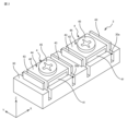
- FIG. 2 is a perspective view showing the terminal block of FIG.
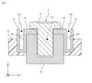
- FIG. 3 is a cross-sectional view of the terminal portion of FIG.
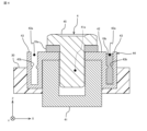
- FIG. 4 is a diagram showing a state in which a bus bar is fastened to the terminal portion of FIG.
- FIG. 5 is a perspective view showing the appearance of a motor drive device according to the second embodiment.
- FIG. 6 is a perspective view showing the terminal block of FIG.
- FIG. 7 is a cross-sectional view of the terminal portion of FIG.
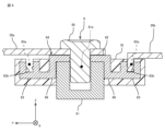
- FIG. 8 is a diagram showing a state in which a bus bar is fastened to the terminal portion of FIG.
- a motor drive device is a device that drives motors installed in robotic devices, injection molding machines, machine tools, lathes, etc.
- a motor drive device converts AC power supplied from an external AC power source into DC power using a converter such as a rectifier, and then converts the DC power into AC power using an inverter.
- the AC power generated by the motor drive device is supplied to the motor as motor drive power, thereby driving the motor.
- the motor drive device has a terminal block that functions as an input/output unit for power.
- the terminal block has a terminal portion for electrically connecting a wiring member inside the housing of the motor drive device with a wiring member outside the housing of the motor drive device.
- One feature of the motor drive device according to this embodiment is that the terminal portion is provided with two types of fixing structures for fixing the wiring member: a screw structure and an insertion structure.
- the screw structure is a structure for fixing the wiring member by using screw tightening.
- the insertion structure is a structure in which the wiring member is inserted and fitted.
- the wiring member will be described as a bus bar.
- the wiring member may be a cable, etc.
- Fig. 1 is a perspective view showing the appearance of a motor drive system 1 including a motor drive device 2 according to the first embodiment.
- the motor drive system 1 is made up of a plurality of motor drive devices 2.
- the motor drive system 1 will be described as being made up of three motor drive devices 2.
- the motor drive system 1 may be made up of two motor drive devices 2, or four or more motor drive devices 2.
- the three motor drive units 2 are arranged in a row, and two adjacent motor drive units are linked and electrically connected by bus bars 10 (10a, 10b).
- the bus bars 10 are linear conductor plates for conducting large currents, and are made of highly conductive metals such as copper, brass, and aluminum.
- the motor drive device 2 has a terminal block 3, and the terminal block 3 has two types of fixing structures, a screw structure and an insertion structure, as structures for fixing wiring members such as the bus bar 10.
- the first bus bar 10a has a through hole for screwing at an end portion, and one end is screwed to the terminal block 3 of the first motor drive device 2 using a screw structure, and the other end is screwed to the terminal block 3 of the second motor drive device 2 using a screw structure. This electrically connects the first motor drive device 2 and the second motor drive device 2.
- the second bus bar 10b has a recess or groove for the insertion structure, and one end is inserted into the terminal block 3 of the second motor drive device 2 using an insertion structure, and the other end is inserted into the terminal block 3 of the third motor drive device 2 using a screw structure. This electrically connects the second motor drive device 2 and the third motor drive device 2.
- the terminal block 3 has a non-conductive terminal seat 30 and at least one terminal portion 4 that functions as a connection terminal to which an external wiring member is connected.
- the terminal block 3 will be described as having two terminal portions 4.
- the two terminal portions 4 are arranged in a row.
- Two recesses 30a are provided in a row on the surface of the terminal seat 30, and two terminal portions 4 are fitted into the two recesses 30a, respectively.
- the two terminal portions 4 fitted into the terminal seat 30 are electrically separated from each other.
- the arrangement direction of the terminal portions 4 is defined as the X direction (also referred to as the up-down direction), the height direction of the terminal portion 4 is defined as the Z direction, and the direction perpendicular to the X direction and the Z direction is defined as the Y direction (also referred to as the left-right direction).
- FIG. 3 is a cross-sectional view of the terminal portion 4 in FIG. 2.
- FIG. 4 is a diagram showing a state in which a busbar is fixed to the terminal portion 4 in FIG. 3.
- the terminal portion 4 has both a screw structure and an insertion structure as a structure for fixing the busbar 10.
- the terminal portion 4 has a screw base 41, a conductive plate 42, a pair of insertion fittings 43, and a terminal screw 45.
- the screw base 41, the conductive plate 42, the pair of insertion fittings 43, and the terminal screw 45 are conductive.
- the screw base 41 is a rectangular parallelepiped, and a screw hole 41a is formed in its surface. The center line of the screw hole 41a is parallel to the Z direction.
- a rectangular conductive plate 42 is arranged on the surface of the screw base 41.
- a through hole continuous with the screw hole 41a of the screw base 41 is formed in the conductive plate 42.
- the screw base 41 or the conductive plate 42 has a connection structure (not shown) to which the wiring members inside the housing of the motor drive device 2 are electrically connected. Through this connection structure, the wiring members inside the housing of the motor drive device 2 are electrically connected directly to the conductive plate 42, or indirectly via the screw base 41.
- the screw base 41 and the terminal screw 45 form a screw structure for fixing the wiring member.
- the bus bar 10a is fixed between the head of the terminal screw 45 and the conductive plate 42 by screwing the terminal screw 45 into the screw hole 41a of the screw base 41, and is electrically connected to the conductive plate 42. Because the screw tightening direction of the screw structure (the center line of the screw hole 41a) is parallel to the Z direction, an operator can fix the bus bar 10a to the screw structure of the terminal part 4 from the front side (+Z direction) of the terminal part 4.
- the insert fitting 43 is configured as a groove frame having a U-shaped cross section. Specifically, the insert fitting 43 is configured of a rectangular bottom plate and a pair of rectangular side plates.
- the groove 43a of the insert fitting 43 which serves as the insertion port for the bus bar, has a depth according to the dimensions of the bus bar.
- a protrusion 43b is provided on the inner surface of each of the pair of side plates of the insert fitting 43.
- the protrusion 43b may be dot-like or linear.
- the pair of insert fittings 43 are disposed vertically and separately across the screw hole 41a of the screw base 41. Specifically, the pair of insert fittings 43 are disposed along the X direction (arrangement direction of the terminal parts 4) on both sides of the screw hole 41a of the screw base 41, with their grooves 43a parallel to the YZ plane.
- the pair of insert fittings 43 are integrally formed with the conductive plate 42.
- the fitting in which the conductive plate 42 and the pair of insert fittings 43 are integrally formed is called a terminal fitting 44.
- the pair of insert fittings 43 may be provided separately from the conductive plate 42 and electrically connected to the conductive plate 42 or the screw base 41 via a conductive connecting member.
- the insertion fittings 43 form an insertion structure that secures the wiring members.
- the busbar 10b is inserted into the groove 43a of the insertion fitting 43, and a recess or groove on the busbar 10b fits into the protrusion 43b of the insertion fitting 43, thereby securing the busbar 10b to the insertion fitting 43 and electrically connecting it to the conductive plate 42.
- the insertion surface of the insertion structure is parallel to the YZ plane and the groove 43a opens on the front side of the terminal portion 4, an operator can secure the busbar 10b to the insertion structure of the terminal portion 4 from the front side (+Z direction) of the terminal portion 4.
- the motor drive device 2 is characterized in that it has two types of fixing structures: a screw structure and an insertion structure.
- a screw structure In the method of fixing the wiring member using the insertion structure, it is only necessary to insert the wiring member into the insertion structure (insertion fitting 43).
- the labor required to line up multiple motor drive devices and connect the motor drive devices with wiring members can be reduced, and the start-up time of the motor drive system 1 can be shortened.
- both the work of screwing the wiring member into the screw structure and the work of inserting the wiring member into the groove (socket) of the insertion structure can be performed from the front side of the terminal portion 4. Therefore, even if the method of connecting the wiring member is changed midway, there is no need to change the arrangement of the motor drive device 2, and the start-up time and correction time of the operator for the motor drive system 1 can be shortened.
- the first motor drive device 2 and the second motor drive device 2 are electrically connected using a screw structure
- the second motor drive device 2 and the third motor drive device 2 are electrically connected using an insert structure.
- the worker can freely combine both the screw structure and the insert structure to configure the motor drive system 1 according to the environment in which the motor drive system 1 is actually configured.
- the motor drive devices 2 can be arranged close to each other, the motor drive devices 2 can be connected to each other with a bus bar in a short time using the insert structure.
- one motor drive device 2 can be arranged at a position away from the other motor drive device 2, and then the motor drive devices 2 can be connected to each other with a cable using the screw structure.
- the worker is given a choice of how to connect the motor drive devices, which improves the freedom of arrangement of the motor drive devices and shortens the time it takes for the worker to start up the motor drive system.
- the insertion fitting 43 which is an example of an insertion structure, is provided integrally with the conductive plate 42 that constitutes the screw structure, and can be configured as a single component fitting. Therefore, by providing both the screw structure and the insertion structure, the terminal block 3 does not become excessively large, and can be manufactured as a single component fitting, which also suppresses increases in manufacturing costs. Therefore, compared to attaching an insertion connector to a terminal block that only has a screw structure, costs can be reduced and the terminal block can be made smaller.
- the busbar can be fixed to the terminal portion 4 simply by inserting it into the insert fitting 43, so the flat busbar used in the screw structure can be simply turned around and inserted into the insert fitting 43 of the insert structure. Therefore, by having the insert fitting 43 have a depth corresponding to the width of the busbar fixed to the terminal portion 4 using the screw structure, the busbar fixed to the terminal portion 4 using the screw structure can also be used as a busbar fixed to the terminal portion 4 using the insert structure.
- the same busbar for the screw structure and the insert structure not only is it possible to suppress increases in parts costs, but it is also possible to flexibly respond to actual connection environments.
- the insertion structure is not limited to that of the first embodiment.
- a motor drive device 6 according to a second embodiment will be described with reference to Figs. 5 to 8.
- the motor drive device 6 according to the second embodiment and the motor drive device 2 according to the first embodiment have different insertion structures. Therefore, in the second embodiment, the insertion structure different from that of the first embodiment will be mainly described.
- FIG. 5 is a perspective view showing the appearance of a motor drive system 5 including a motor drive device 6 according to the second embodiment.
- the motor drive system 5 is composed of multiple motor drive devices 6.
- the motor drive device 6 has a terminal block 7, and the terminal block 7 has two types of fixing structures, a screw structure and an insertion structure, for fixing wiring members such as bus bars.
- the three motor drive devices 6 that make up the motor drive system 5 are arranged in a row, and two adjacent motor drive devices 6 are connected by bus bars 20 (20a, 20b).
- the bus bar 20a is a linear conductor plate, and through holes are drilled at both ends so that the bus bar 20 can be screwed to the motor drive devices 6.
- the bus bar 20b is configured to have both ends bent in the same direction, forming an overall U-shape.
- FIG. 6 is a perspective view showing an example of the terminal block 7 of FIG. 5.
- the terminal block 7 has a non-conductive terminal base 70 and at least one terminal portion 8 that functions as a connection terminal to which an external wiring member is connected.
- the terminal block 7 is described as having two terminal portions 8.
- the two terminal portions 8 fitted into the terminal base 70 are arranged in a row and held electrically isolated from each other.
- the arrangement direction of the terminal portions 8 is defined as the X direction (also referred to as the up-down direction)
- the height direction of the terminal portion 8 is defined as the Z direction
- the direction perpendicular to the X direction and Z direction is defined as the Y direction (also referred to as the left-right direction).
- FIG. 7 is a cross-sectional view of the terminal portion 8 in FIG. 6.
- FIG. 8 is a diagram showing a state in which a bus bar is fixed to the terminal portion 8 in FIG. 7.
- the terminal portion 8 is provided with a screw structure for fixing a wiring member and an insertion structure.
- the screw structure of the second embodiment is the same as that of the first embodiment. Therefore, a detailed description of the screw structure of the second embodiment is omitted.
- the bus bar 20a is fixed between the screw head of the terminal screw 85 and the conductive plate 82 by screwing the terminal screw 85 into the screw hole 81a of the screw base 81, and is electrically connected to the conductive plate 82.
- the screw base 81 and the terminal screw 85 constitute a screw structure for fixing the wiring member. Since the screw tightening direction of the screw structure (the center line of the screw hole 81a) is parallel to the Z direction, an operator can fix the bus bar 20a to the screw structure of the terminal portion 8 from the front side (+Z direction) of the terminal
- the insertion fitting 83 is configured as a groove frame having a U-shaped cross section. Specifically, the insertion fitting 83 is configured of a rectangular bottom plate and a pair of rectangular side plates. The groove 83a of the insertion fitting 83 has a depth according to the dimensions of the busbar. A protrusion 83b is provided on the inner surface of each of the pair of side plates of the insertion fitting 83. As shown in FIG. 6, the pair of insertion fittings 43 are distributed and arranged on the left and right sides of the screw hole 81a of the screw base 81.
- the pair of insertion fittings 83 are arranged along the Y direction (the direction perpendicular to the arrangement direction of the terminal parts 8) on both sides of the screw hole 81a of the screw base 81, with their grooves 83a parallel to the XZ plane.
- the pair of insert fittings 83 are formed integrally with the conductive plate 82.
- the fitting in which the conductive plate 82 and the pair of insert fittings 83 are formed integrally is called a terminal fitting 84.
- the pair of insert fittings 83 are each connected to both ends of the conductive plate 82 via an L-shaped conductive connecting fitting 86.
- the pair of insert fittings 83 may be provided separately from the conductive plate 82 and electrically connected to the conductive plate 82 or the screw base 81 via a conductive connecting member.
- the insertion fitting 83 constitutes an insertion structure that fixes the wiring member. Specifically, the bent portion of the end of the busbar 20b is inserted into the groove 83a of the insertion fitting 83, and the recess or groove of the busbar 20b fits into the protrusion 83b, thereby fixing the busbar 20b to the insertion fitting 83 and electrically connecting it to the conductive plate 82. Because the insertion surface of the insertion structure is parallel to the XZ plane and the groove 83a opens on the front side of the terminal portion 8, an operator can fix the busbar 20b to the insertion structure of the terminal portion 8 from the front side (+Z direction) of the terminal portion 8.
- the motor drive device 6 according to the second embodiment like the motor drive device 2 according to the first embodiment, is characterized in that it has two types of fixing structures for the wiring members: a screw structure and an insertion structure. As a result, the motor drive device 6 according to the second embodiment achieves the same effects as the motor drive device 2 according to the first embodiment.
- the terminal block includes a pair of fittings.
- the number of fittings provided on the terminal block may be one, or three or more.
- the pair of insert fittings 43 are provided distributed above and below the screw hole 41a of the screw base 41. However, the pair of insert fittings 43 may be arranged side by side only on the upper side or only on the lower side of the screw hole 41a of the screw base 41.
- the pair of insert fittings 83 are provided distributed to the left and right sides of the screw hole 81a of the screw base 81. However, the pair of insert fittings 83 may be arranged side by side only on the left side or only on the right side of the screw hole 81a of the screw base 81.
- the pair of insert fittings 43 of the first embodiment and the pair of insert fittings 83 of the second embodiment can coexist.
- the terminal block of the motor drive device may be configured to have a pair of insert fittings 43 of the first embodiment and a pair of insert fittings 83 of the second embodiment.
- the terminal block of the motor drive device may have a plurality of insert fittings distributed around the screw hole.
- the multiple insertion fittings may be arranged so that the insertion surfaces are not parallel to each other.
- the insertion structure is an insertion fitting having a U-shaped cross section, and the insertion fitting is provided with a protrusion that fits into a recess or groove in the wiring member.
- the structure is not limited to this, so long as the wiring member can be inserted and fixed.
- the insertion fitting may not be provided with a protrusion, and the pair of side plates that make up the insertion fitting may be biased in a direction toward each other so that the wiring member can be sandwiched between them.
- a protrusion to prevent the wiring member inserted into the insertion fitting from coming out may be provided on the inner surface of each of the pair of side plates that make up the insertion fitting.
- the terminal block is a distinctive feature of the motor drive device according to this embodiment. Therefore, the terminal block provided in the motor drive device according to this embodiment achieves the same effects as the motor drive device according to this embodiment, even when used as an independent device or when incorporated into a device other than the motor drive device.
- the motor drive device 2 has a terminal block 3.
- the terminal block 3 has a plurality of terminal portions 4 and a seat 30 that holds the plurality of terminal portions 4.
- Each of the terminal portions 4 is provided with a screw structure and an insertion structure for fixing an external wiring member 10.
- the insertion structure is an insertion fitting 43 having a U-shaped cross section into which the wiring member 10 is inserted.
- the terminal portion 4 has a screw base 41 having a screw hole 41a, and a terminal metal fitting 44 arranged on the surface of the screw base 41.
- the insertion metal fitting 43 is formed integrally with the terminal metal fitting 44.
- the insertion structure has another insertion metal fitting 43 having a U-shaped cross section into which the wiring member is inserted, and the insertion metal fitting 43 and the other insertion metal fitting 43 are distributed on both sides of the screw base 41.
- Appendix 5 In the motor drive device 2 described in Appendix 4, the multiple terminals 4 are arranged and held in a row, and the insertion fittings 43 are arranged along the direction in which the terminals 4 are arranged.
- the motor drive system 1 includes at least three motor drive devices 2. Each of the motor drive devices 2 is configured by the motor drive device 2 described in any one of Supplementary Notes 1 to 6. Of the at least three motor drive devices 2, a first motor drive device 2 and a second motor drive device 2 are electrically connected by a wiring member 10 fixed by a screw structure. Of the at least three motor drive devices 2, a second motor drive device 2 and a third motor drive device 2 are electrically connected by a wiring member 10 fixed by an insertion structure. (Appendix 8)
- the terminal block 3 includes at least one terminal portion 4 and a non-conductive terminal seat 30 that separately holds the at least one terminal portion 4.
- the terminal portion 4 is provided with a screw structure and an insertion structure for fixing an external wiring member 10.
Landscapes
- Motor Or Generator Frames (AREA)
- Connections Arranged To Contact A Plurality Of Conductors (AREA)
Abstract
Description
以下、図1乃至図4を参照して第1実施形態に係るモータ駆動装置を説明する。図1は、第1実施形態に係るモータ駆動装置2を含むモータ駆動システム1の外観を示す斜視図である。図1に示すように、モータ駆動システム1は、複数のモータ駆動装置2により構成される。ここでは、モータ駆動システム1は3つのモータ駆動装置2により構成されるものとして説明する。しかしながら、モータ駆動システム1は、2つのモータ駆動装置2により構成されてもよいし、4つ以上のモータ駆動装置2により構成されてもよい。
図2は、図1の端子台3の一例を示す斜視図である。図2に示すように、端子台3は、非導電性の端子台座30と、外部の配線部材が接続される接続端子として機能する少なくとも1つの端子部4とを有する。ここでは、端子台3は2つの端子部4を有するものとして説明する。2つの端子部4は一列に配列されている。端子台座30の表面には2つの窪み30aが一列に沿って設けられ、2つの窪み30aに2つの端子部4がそれぞれ嵌め込まれる。端子台座30に嵌め込まれた2つの端子部4は、相互に電気的に分離される。ここでは、端子部4の配列方向をX方向(上下方向ともいう)、端子部4の高さ方向をZ方向、X方向とZ方向とに直交する方向をY方向(左右方向ともいう)として定義する。
挿嵌構造は第1実施形態に限定されない。以下、図5乃至図8を参照して、第2実施形態に係るモータ駆動装置6を説明する。第2実施形態に係るモータ駆動装置6と第1実施形態に係るモータ駆動装置2とは、挿嵌構造が相違する。そのため、第2実施形態では、第1実施形態と相違する挿嵌構造を中心に説明する。
(付記1)
モータ駆動装置2は端子台3を有する。端子台3は、複数の端子部4と、複数の端子部4を保持する台座30とを有する。端子部4各々には、外部の配線部材10を固定するためのネジ構造と挿嵌構造とが併設される。
(付記2)
付記1に記載のモータ駆動装置2において、挿嵌構造は配線部材10が挿嵌される横断面U字形の挿嵌金具43である。
(付記3)
付記2のモータ駆動装置2において、端子部4は、ネジ孔41aを有するネジ台座41と、ネジ台座41の表面に配置される端子金具44と、を有する。挿嵌金具43は、端子金具44に一体的に形成されている。
(付記4)
付記3に記載のモータ駆動装置2において、挿嵌構造は配線部材が挿嵌される横断面U字形の他の挿嵌金具43を有し、挿嵌金具43と他の挿嵌金具43はネジ台座41を挟んで両側に分散配置される。
(付記5)
付記4に記載のモータ駆動装置2において、複数の端子部4は一列に配列保持され、挿嵌金具43は、端子部4の配列方向に沿って配置される。
(付記6)
付記4に記載のモータ駆動装置2において、複数の端子部4は一列に配列保持され、挿嵌金具43は、端子部4の配列方向と直交する方向に沿って配置される。
(付記7)
モータ駆動システム1は、少なくとも3つのモータ駆動装置2を備える。モータ駆動装置2各々は、付記1乃至付記6のいずれか一項に記載のモータ駆動装置2により構成される。少なくとも3つのモータ駆動装置2のうち第1のモータ駆動装置2と第2のモータ駆動装置2とは、ネジ構造により固定された配線部材10により電気的に接続される。少なくとも3つのモータ駆動装置2のうち第2のモータ駆動装置2と第3のモータ駆動装置2とは、挿嵌構造により固定された配線部材10により電気的に接続される。
(付記8)
端子台3は、少なくとも1つの端子部4と、少なくとも1つの端子部4を分離保持する非導電性の端子台座30と、を具備する。端子部4には、外部の配線部材10を固定するためのネジ構造と挿嵌構造とが併設される。
Claims (8)
- 端子台を有するモータ駆動装置であって、
前記端子台は、
複数の端子部と、
前記複数の端子部を保持する端子台座と、
を有し、
前記端子部各々には、外部の配線部材を固定するためのネジ構造と挿嵌構造とが併設される、モータ駆動装置。 - 前記挿嵌構造は前記配線部材が挿嵌される横断面U字形の挿嵌金具である、請求項1に記載のモータ駆動装置。
- 前記端子部は、
ネジ孔を有するネジ台座と、
前記ネジ台座の表面に配置される端子金具と、を有し、
前記挿嵌金具は、前記端子金具に一体的に形成されている、
請求項2記載のモータ駆動装置。 - 前記端子部は、前記挿嵌金具と一対をなす他の挿嵌金具をさらに有し、
前記挿嵌金具と前記他の挿嵌金具は前記ネジ台座を挟んで両側に分散配置される、
請求項3記載のモータ駆動装置。 - 前記複数の端子部は一列に配列保持され、
前記挿嵌金具は、前記端子部の配列方向に沿って配置される、請求項4記載のモータ駆動装置。 - 前記複数の端子部は一列に配列保持され、
前記挿嵌金具は、前記端子部の配列方向と直交する方向に沿って配置される、請求項4記載のモータ駆動装置。 - 少なくとも3つのモータ駆動装置を備えるモータ駆動システムであって、
前記モータ駆動装置各々は、請求項1乃至請求項6のいずれか一項に記載のモータ駆動装置により構成され、
前記少なくとも3つのモータ駆動装置のうち第1のモータ駆動装置と第2のモータ駆動装置とは、前記ネジ構造により固定された配線部材により電気的に接続され、
前記少なくとも3つのモータ駆動装置のうち第2のモータ駆動装置と第3のモータ駆動装置とは、前記挿嵌構造により固定された配線部材により電気的に接続される、
モータ駆動システム。 - 少なくとも1つの端子部と、
前記少なくとも1つの端子部を分離保持する非導電性の端子台座と、を具備し、
前記端子部には、外部の配線部材を固定するためのネジ構造と挿嵌構造とが併設される、
端子台。
Priority Applications (2)
| Application Number | Priority Date | Filing Date | Title |
|---|---|---|---|
| JP2025516320A JPWO2024224439A1 (ja) | 2023-04-24 | 2023-04-24 | |
| PCT/JP2023/016059 WO2024224439A1 (ja) | 2023-04-24 | 2023-04-24 | 端子台、モータ駆動装置及びモータ駆動システム |
Applications Claiming Priority (1)
| Application Number | Priority Date | Filing Date | Title |
|---|---|---|---|
| PCT/JP2023/016059 WO2024224439A1 (ja) | 2023-04-24 | 2023-04-24 | 端子台、モータ駆動装置及びモータ駆動システム |
Publications (1)
| Publication Number | Publication Date |
|---|---|
| WO2024224439A1 true WO2024224439A1 (ja) | 2024-10-31 |
Family
ID=93255984
Family Applications (1)
| Application Number | Title | Priority Date | Filing Date |
|---|---|---|---|
| PCT/JP2023/016059 Ceased WO2024224439A1 (ja) | 2023-04-24 | 2023-04-24 | 端子台、モータ駆動装置及びモータ駆動システム |
Country Status (2)
| Country | Link |
|---|---|
| JP (1) | JPWO2024224439A1 (ja) |
| WO (1) | WO2024224439A1 (ja) |
Citations (3)
| Publication number | Priority date | Publication date | Assignee | Title |
|---|---|---|---|---|
| JP2018078724A (ja) * | 2016-11-09 | 2018-05-17 | ファナック株式会社 | モータ駆動装置 |
| JP2018081826A (ja) * | 2016-11-16 | 2018-05-24 | ファナック株式会社 | 接続部材およびそれを具備するモータ駆動装置 |
| JP2018098863A (ja) * | 2016-12-09 | 2018-06-21 | ファナック株式会社 | ショートバー、ショートバーユニットおよびモータ駆動装置 |
-
2023
- 2023-04-24 JP JP2025516320A patent/JPWO2024224439A1/ja active Pending
- 2023-04-24 WO PCT/JP2023/016059 patent/WO2024224439A1/ja not_active Ceased
Patent Citations (3)
| Publication number | Priority date | Publication date | Assignee | Title |
|---|---|---|---|---|
| JP2018078724A (ja) * | 2016-11-09 | 2018-05-17 | ファナック株式会社 | モータ駆動装置 |
| JP2018081826A (ja) * | 2016-11-16 | 2018-05-24 | ファナック株式会社 | 接続部材およびそれを具備するモータ駆動装置 |
| JP2018098863A (ja) * | 2016-12-09 | 2018-06-21 | ファナック株式会社 | ショートバー、ショートバーユニットおよびモータ駆動装置 |
Also Published As
| Publication number | Publication date |
|---|---|
| JPWO2024224439A1 (ja) | 2024-10-31 |
Similar Documents
| Publication | Publication Date | Title |
|---|---|---|
| JP5836811B2 (ja) | ねじ締めブロックの接続構造 | |
| JP4597659B2 (ja) | ジャンクションブロック | |
| JP2005322554A (ja) | 電気機器の端子装置 | |
| CN110073588B (zh) | 电容器单元、电动压缩机 | |
| JP6403273B2 (ja) | 電気機器の接続装置 | |
| JP2019009389A (ja) | 電気機器及び分電盤 | |
| US10218096B2 (en) | Short bar, short bar unit, and motor drive device | |
| US10389214B2 (en) | Motor and producing method for motor | |
| TW201440615A (zh) | 馬達驅動裝置 | |
| JP5570313B2 (ja) | 電気接続箱 | |
| WO2024224439A1 (ja) | 端子台、モータ駆動装置及びモータ駆動システム | |
| EP3806295A1 (en) | Control device and motor device | |
| JP4149352B2 (ja) | ジャンクションブロックの接続構造 | |
| JP2000261936A (ja) | Ev用電気接続ユニットの組付構造 | |
| JP2003257516A (ja) | ブスバー及びそれを用いた電源装置 | |
| JP5268863B2 (ja) | 電力用接続導体 | |
| CN111480267A (zh) | 端子台以及空调装置 | |
| CN113437592B (zh) | 连接装置和机电组件 | |
| CN116667076A (zh) | 端子座、电气设备 | |
| US5267124A (en) | Controlling apparatus with terminal arrangement | |
| CN115915690B (zh) | 控制器 | |
| JP2008253119A (ja) | 分電盤 | |
| JP4625385B2 (ja) | 配電盤 | |
| JP4983640B2 (ja) | 低圧配電設備 | |
| WO2025126316A1 (ja) | ブスバー接続されるモータ駆動装置 |
Legal Events
| Date | Code | Title | Description |
|---|---|---|---|
| 121 | Ep: the epo has been informed by wipo that ep was designated in this application |
Ref document number: 23935222 Country of ref document: EP Kind code of ref document: A1 |
|
| ENP | Entry into the national phase |
Ref document number: 2025516320 Country of ref document: JP Kind code of ref document: A |
|
| WWE | Wipo information: entry into national phase |
Ref document number: 2025516320 Country of ref document: JP |
|
| NENP | Non-entry into the national phase |
Ref country code: DE |
|
| 122 | Ep: pct application non-entry in european phase |
Ref document number: 23935222 Country of ref document: EP Kind code of ref document: A1 |