WO2024218908A1 - 光ファイバケーブルおよびコネクタ付きケーブル - Google Patents
光ファイバケーブルおよびコネクタ付きケーブル Download PDFInfo
- Publication number
- WO2024218908A1 WO2024218908A1 PCT/JP2023/015641 JP2023015641W WO2024218908A1 WO 2024218908 A1 WO2024218908 A1 WO 2024218908A1 JP 2023015641 W JP2023015641 W JP 2023015641W WO 2024218908 A1 WO2024218908 A1 WO 2024218908A1
- Authority
- WO
- WIPO (PCT)
- Prior art keywords
- optical fiber
- fiber cable
- cable
- cable according
- jacket
- Prior art date
- Legal status (The legal status is an assumption and is not a legal conclusion. Google has not performed a legal analysis and makes no representation as to the accuracy of the status listed.)
- Ceased
Links
Images


Classifications
-
- G—PHYSICS
- G02—OPTICS
- G02B—OPTICAL ELEMENTS, SYSTEMS OR APPARATUS
- G02B6/00—Light guides; Structural details of arrangements comprising light guides and other optical elements, e.g. couplings
- G02B6/44—Mechanical structures for providing tensile strength and external protection for fibres, e.g. optical transmission cables
- G02B6/4401—Optical cables
- G02B6/4429—Means specially adapted for strengthening or protecting the cables
- G02B6/443—Protective covering
- G02B6/4432—Protective covering with fibre reinforcements
- G02B6/4433—Double reinforcement laying in straight line with optical transmission element
-
- G—PHYSICS
- G02—OPTICS
- G02B—OPTICAL ELEMENTS, SYSTEMS OR APPARATUS
- G02B6/00—Light guides; Structural details of arrangements comprising light guides and other optical elements, e.g. couplings
- G02B6/44—Mechanical structures for providing tensile strength and external protection for fibres, e.g. optical transmission cables
- G02B6/4401—Optical cables
- G02B6/4403—Optical cables with ribbon structure
-
- G—PHYSICS
- G02—OPTICS
- G02B—OPTICAL ELEMENTS, SYSTEMS OR APPARATUS
- G02B6/00—Light guides; Structural details of arrangements comprising light guides and other optical elements, e.g. couplings
- G02B6/44—Mechanical structures for providing tensile strength and external protection for fibres, e.g. optical transmission cables
- G02B6/4401—Optical cables
- G02B6/4429—Means specially adapted for strengthening or protecting the cables
- G02B6/443—Protective covering
- G02B6/4432—Protective covering with fibre reinforcements
-
- G—PHYSICS
- G02—OPTICS
- G02B—OPTICAL ELEMENTS, SYSTEMS OR APPARATUS
- G02B6/00—Light guides; Structural details of arrangements comprising light guides and other optical elements, e.g. couplings
- G02B6/44—Mechanical structures for providing tensile strength and external protection for fibres, e.g. optical transmission cables
- G02B6/4401—Optical cables
- G02B6/4429—Means specially adapted for strengthening or protecting the cables
- G02B6/4434—Central member to take up tensile loads
-
- G—PHYSICS
- G02—OPTICS
- G02B—OPTICAL ELEMENTS, SYSTEMS OR APPARATUS
- G02B6/00—Light guides; Structural details of arrangements comprising light guides and other optical elements, e.g. couplings
- G02B6/44—Mechanical structures for providing tensile strength and external protection for fibres, e.g. optical transmission cables
- G02B6/4401—Optical cables
- G02B6/4429—Means specially adapted for strengthening or protecting the cables
- G02B6/4436—Heat resistant
Definitions
- This disclosure relates to optical fiber cables and cables with connectors.
- Patent Document 1 discloses an optical fiber cable that includes multiple optical fiber cores, a strength member, and an outer jacket that covers the multiple optical fiber cores from the outside and contains the strength member.
- the strength member makes it relatively easy to bend the cable, and provides the cable with tensile strength and anti-buckling properties.
- An optical fiber cable includes: a cable core including a plurality of optical fiber cores; At least one strength member disposed along the cable core; an outer jacket that covers the cable core from the outside and contains the tension members, The tension member is provided at one location of the outer sheath in a cross-sectional view,
- the core density calculated by dividing the number of cores in the plurality of optical fibers by the cross-sectional area of the cable, is 1.5 cores/mm2 or more.
- a connector-attached cable includes: The optical fiber cable; and a multi-fiber connector to which the plurality of optical fiber cores are attached at one end of the optical fiber cable.
- FIG. 1 is a cross-sectional view perpendicular to the longitudinal direction of an optical fiber cable according to an embodiment of the present invention.
- FIG. 2 is a cross-sectional view perpendicular to the longitudinal direction of an optical fiber cable according to a modified example.
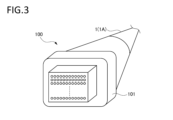
- FIG. 3 is a schematic diagram illustrating a cable with connectors.
- an optical fiber cable has a structure in which the cable core is at the center and has strength members on both sides of the jacket, the cable tends to bend easily in a 90-degree direction relative to a line connecting the strength members in a cross-sectional view, and the bending rigidity in that direction tends to be low.
- the cable tends to bend less easily in the direction in which the strength members are located, and the bending rigidity in that direction tends to be high.
- an optical fiber cable with the above structure has bending anisotropy. When air is pumped or pushed through a duct, such an optical fiber cable tends to bend in a direction with low bending rigidity, and may buckle midway through the duct.
- optical fiber cables are known in which, in a cross-sectional view, four equally spaced tension members are arranged on the outer sheath.
- the distance between the tension members embedded in the outer sheath and the bending center (in this case, the bending center coincides with the center of the cable) is large.
- compressive stress is applied to the inside of the bend, making the tension members arranged on the inside prone to buckling, breaking and being crushed.
- a large space is required to store the cable.
- optical fiber cables in order to mount the optical fiber cores at high density, it is preferable for optical fiber cables to be thin and lightweight, and the optical fiber diameter has also been reduced from the conventional 250 ⁇ m to 200 ⁇ m. To achieve high density, it is effective to make the outer jacket thinner, but if the outer jacket is thinner, the tensile members located on the inside become more likely to buckle when the cable is bent to a small diameter.
- the present disclosure aims to provide an optical fiber cable and a cable with connectors that can pack optical fiber cores at high density and in which the tensile members are less likely to buckle even when the cable is bent to a small diameter.
- An optical fiber cable includes: (1) a cable core including a plurality of optical fiber cores; At least one strength member disposed along the cable core; an outer jacket that covers the cable core from the outside and contains the tension members, The tension member is provided at one location of the outer sheath in a cross-sectional view,
- the core density calculated by dividing the number of cores in the plurality of optical fibers by the cross-sectional area of the cable, is 1.5 cores/mm2 or more.
- an optical fiber cable with a core density of 1.5 cores/mm2 or more and a high density of optical fibers can be realized.
- the strength member is provided at one location in the jacket in a cross-sectional view. By embedding the strength member at one location, the bending center when the cable is bent is closer to the strength member, and the distance between the strength member and the bending center is shorter. Therefore, compared to a case where the strength member is embedded at two or more locations in the jacket, the strength member is less likely to buckle even when the cable is bent to a small diameter. Since the cable can be easily bent to a small diameter, the cable can be easily stored in any space.
- the tensile member may be fiber-reinforced plastic (FRP).
- the tensile member is made of FRP, it has relatively high rigidity and is less likely to buckle.
- the Young's modulus of the tensile member may be 400 MPa or more and 700 MPa or less.
- the tensile body is provided at one location on the outer sheath, and the Young's modulus of the tensile body is 400 MPa or more and 700 MPa or less, so the rigidity of the tensile body is relatively low, and the tensile body is relatively flexible and less prone to buckling. If the Young's modulus of the tensile body falls below 400 MPa, its function as a tensile body decreases, and its function as a compression resistance body decreases in response to the shrinkage of the outer sheath. On the other hand, if the Young's modulus of the tensile body exceeds 700 MPa, the cable becomes difficult to bend, and storage becomes less convenient.
- the product of Young's modulus and cross-sectional area (ES product) of the tensile body may be 1000 N or more and 10000 N or less.
- the tensile body is provided at one location on the outer sheath, and the ES product of the tensile body is 1,000 N or more and 10,000 N or less, so the tensile body is less likely to buckle.
- the tensile member may be a steel wire.
- the tensile body is provided at one location on the outer sheath, and since the tensile body is made of steel wire, it has high rigidity and is less likely to buckle.
- the diameter of the tensile member may be greater than the minimum thickness of the outer sheath.
- the tension member is provided at one location on the outer sheath, and the diameter of the tension member is greater than the minimum thickness of the outer sheath, so the center of rigidity of the cable is closer to the tension member than to the center of the cable. This makes it difficult for the tension member to buckle even when the cable is bent.
- the tensile member when the optical fiber cable is bent with a bending radius that is 10 times the radius of the optical fiber cable, the tensile member may not buckle.
- the outer coating may contain a flame-retardant inorganic material.
- the outer sheath contains a flame-retardant inorganic material, it is possible to realize an optical fiber cable with excellent flame retardancy.
- the outer coating may be ethylene-vinyl acetate copolymer resin (EVA resin).
- the outer sheath is made of ethylene-vinyl acetate copolymer resin (EVA resin), making it possible to realize an optical fiber cable with excellent flame retardancy.
- EVA resin ethylene-vinyl acetate copolymer resin
- the Young's modulus of the outer covering may be 400 MPa or more and 800 MPa or less.
- the Young's modulus of the outer jacket is 400 MPa or more and 800 MPa or less, making the cable easier to bend and improving the cable's ability to be stored in any space.
- the softening point temperature of the outer covering may be 40°C or higher and 70°C or lower.
- the softening point temperature of the jacket is lower than 40°C, the jacket will easily soften even in a normal temperature environment, and the cable will easily deform due to lateral pressure, etc. If the softening point temperature of the jacket is higher than 70°C, the material will harden, and transmission characteristics at low temperatures will be easily deteriorated due to low-temperature shrinkage, etc. According to the present disclosure, since the softening point temperature of the jacket is between 40°C and 70°C, it is possible to realize an optical fiber cable that is less likely to deform even when lateral pressure, etc. is applied, and that has good transmission characteristics even at low temperatures.
- the tensile member may be arranged in a spiral shape around the cable core in the longitudinal direction of the optical fiber cable.
- the tensile members are arranged in a spiral shape, which reduces bending anisotropy and further suppresses cable buckling.
- the ratio of the area of the tensile member to the area of the outer sheath in the cross-sectional view may be 0.04 or more.
- the ratio of the area of the tensile body to the area of the outer sheath is less than 0.04, its function as a tensile body is reduced, and its function as a compression resistance body is reduced when the outer sheath shrinks. According to the present disclosure, since the ratio of the area of the tensile body to the area of the outer sheath is 0.04 or more, the tensile body is less likely to buckle.
- the optical fiber cable may be an air pressure transmission cable.
- This disclosure makes it possible to realize an optical fiber cable for air pressure transmission that can pack optical fiber cores at a high density and in which the tensile members are less likely to buckle even when the cable is bent to a small diameter.
- a connector-attached cable includes: (15) An optical fiber cable according to any one of (1) to (14) above; and a multi-fiber connector to which the plurality of optical fiber cores are attached at one end of the optical fiber cable.
- This disclosure makes cable connections easier.
- FIG. 1 is a cross-sectional view of the optical fiber cable 1 taken along a line perpendicular to the longitudinal direction.
- the optical fiber cable 1 includes a cable core 11, one tensile member 12, and an outer sheath 13.
- the optical fiber cable 1 is circular in cross section.
- the outer diameter of the optical fiber cable 1 is, for example, 9.8 mm.
- a pressure winding tape or bundling string may be wound around the outer periphery of the cable core 11.
- the optical fiber cable 1 of this embodiment is a slotless type optical fiber cable and is a cable for air pressure transmission.
- the cable core 11 is circular in cross section.
- the cable core 11 includes a plurality of optical fiber ribbons 10.
- the outer diameter of the cable core 11 is, for example, 5.8 mm.
- the cable core 11 has 24 optical fiber ribbons 10.
- the optical fiber ribbon 10 includes 12 optical fiber cores.
- the outer diameter of each optical fiber core is, for example, 165 ⁇ m or more and 250 ⁇ m or less, which is relatively thin.
- the 12 optical fiber cores are arranged in parallel in a direction perpendicular to the longitudinal direction. At least some of the adjacent optical fiber cores of the optical fiber ribbon 10 may have a connection portion where the adjacent optical fiber cores are connected and a non-connection portion where the adjacent optical fiber cores are not connected, which are intermittently provided in the longitudinal direction of the optical fiber cores.
- the optical fiber ribbon 10 is an example of a plurality of optical fiber cores.
- the core density calculated by dividing the number of cores in the multiple optical fiber cores by the cable cross-sectional area, is 1.5 cores/ mm2 or more.
- the optical fiber cable 1 of this embodiment has 288 optical fiber cores in the cable core 11.
- the cable cross-sectional area is 75.39 mm2 .
- the core density is 3.8 cores/ mm2 .
- the tensile strength member 12 is arranged along the cable core 11.
- the tensile strength member 12 is arranged in a spiral shape around the cable core 11 in the longitudinal direction of the optical fiber cable 1.
- the tensile strength member 12 is further provided at one location on the outer jacket 13 in a cross-sectional view.
- the strength member 12 is made of fiber reinforced plastic (FRP). Examples of fiber reinforced plastic include aramid FRP, glass FRP, and carbon FRP.
- FRP fiber reinforced plastic
- the strength member 12 is circular in cross section.
- the diameter of the strength member 12 is, for example, 1.8 mm.
- the diameter of the strength member 12 is greater than the minimum thickness Tmin of the outer jacket 13, which will be described later.
- the ratio of the area of the strength member 12 to the area of the outer jacket 13 in cross section is 0.04 or more.
- the Young's modulus of the tensile member 12 is 400 MPa or more and 700 MPa or less.
- the product of the Young's modulus of the tensile member 12 and the cross-sectional area of the tensile member 12 (ES product) is 1000 N or more and 10000 N or less.
- the tension members 12 are provided so as not to buckle when the optical fiber cable 1 is bent at a bending radius ten times the radius of the optical fiber cable 1. For example, in the case of the optical fiber cable 1 having an outer diameter of 9.8 mm as described above, the tension members 12 will not buckle even if the optical fiber cable 1 is bent so that the bending radius is 49 mm.
- the outer jacket 13 is provided to cover the cable core 11 from the outside and to enclose the tensile member 12.
- the base resin of the outer jacket 13 in this embodiment is ethylene-vinyl acetate copolymer resin (EVA resin).
- the outer jacket 13 may contain a flame-retardant inorganic material.
- the outer jacket 13 contains, for example, magnesium hydroxide or aluminum hydroxide.
- the Young's modulus of the outer jacket 13 in this embodiment is 400 MPa or more and 800 MPa or less.
- the softening point temperature of the outer jacket 13 is 40°C or more and 70°C or less.
- the thickness of the outer jacket 13 is not constant, and the minimum thickness is Tmin.
- the minimum thickness Tmin of the outer jacket 13 is the thickness of the outer jacket portion where the length between the cable core 11 and the outer edge of the optical fiber cable 1 is the shortest.
- the minimum thickness Tmin of the outer jacket 13 is the thickness of the outer jacket 13 located on the opposite side of the cable core 11 to the strength member 12 in a cross-sectional view ( Figure 1).
- the diameter of the strength member 12 is 1.8 mm
- the minimum thickness Tmin of the outer jacket 13 is 1.3 mm. In this way, the diameter of the strength member 12 is greater than the minimum thickness Tmin of the outer jacket 13.
- the ratio of the area of the strength members 12 to the area of the outer sheath 13 is 0.04 or more.
- the ratio of the area of the strength members 12 to the area of the outer sheath 13 is 0.05.
- the optical fiber cable 1 of this embodiment includes the cable core 11 including a plurality of optical fiber ribbons 10, one strength member 12 arranged along the cable core 11, and the jacket 13 that covers the cable core 11 from the outside and encases the strength member 12.
- the core density calculated by dividing the number of core fibers of the plurality of optical fiber cores by the cable cross-sectional area, is 1.5 cores/mm2 or more . Therefore, it is possible to realize the optical fiber cable 1 in which optical fiber cores are packed at a high density.
- the tensile strength member 12 is provided at one location on the outer jacket 13 in a cross-sectional view. Therefore, when the optical fiber cable 1 is bent, the center of bending is closer to the tensile strength member 12, and the distance between the tensile strength member 12 and the bending center is shorter. Therefore, compared to when the tensile strength member 12 is embedded in two or more locations in the outer jacket 13, the tensile strength member 12 is less likely to buckle even when the optical fiber cable 1 is bent to a small diameter. Because the optical fiber cable 1 can be easily bent to a small diameter, the storage ability of the optical fiber cable 1 in any space is also improved.
- Fig. 2 is a cross-sectional view perpendicular to the longitudinal direction of the optical fiber cable 1A.
- the optical fiber cable 1 illustrated in Fig. 1 has one tensile member 12, whereas the optical fiber cable 1A illustrated in Fig. 2 has two tensile members 12A provided at one location on the jacket 13 in the cross-sectional view.
- the two strength members 12A are adjacent to each other and form a pair of strength member sets 12S.
- the pair of strength member sets 12S are provided at one location of the jacket 13.
- Each strength member 12A is circular in cross-sectional view.
- the diameter of each strength member 12A is, for example, 1.2 mm.
- the ratio of the area of the strength members 12A to the area of the jacket 13 in cross-sectional view is 0.04 or more.
- the cable cross-sectional area is 75.4 mm 2.
- the cable core area is 26.4 mm 2. Therefore, the area of the jacket 13 is 49.0 mm 2.
- the area of the two strength members 12A is 2.26 mm 2. Therefore, the ratio of the area of the strength members 12A to the area of the jacket 13 in cross-sectional view is 0.046.
- two tensile members 12A are also provided at one location on the outer sheath 13.
- the bending center is closer to the two tensile members 12A, and the distance between the two tensile members 12A and the bending center is shorter. Therefore, the two tensile members 12A are less likely to buckle. Since the optical fiber cable 1A can be easily bent to a small diameter, the optical fiber cable 1A can be more easily stored in any space.
- the tensile body 12 is fiber reinforced plastic (FRP), but the tensile body 12 is not limited to fiber reinforced plastic (FRP).
- the tensile body 12 may be a steel wire. In this case, since the rigidity of the tensile body 12 is relatively high, the tensile body 12 is less likely to buckle even when the optical fiber cable 1 is bent.
- the tensile strength members 12 are arranged in a spiral shape around the cable core 11 in the longitudinal direction of the optical fiber cable 1, but the arrangement of the tensile strength members 12 is not limited to a spiral shape.
- the tensile strength members 12 may be arranged in a linear shape along the cable core 11 in the longitudinal direction of the optical fiber cable 1.
- a multi-core connector 101 may be provided at one end of the optical fiber cable 1 or the optical fiber cable 1A.
- FIG. 3 is a schematic diagram illustrating a connectorized cable 100. As shown in FIG. 3, the connectorized cable 100 includes the optical fiber cable 1 and a multi-core connector 101 to which multiple optical fiber cores are attached at one end of the optical fiber cable 1.
- the connectorized cable 100 may include an optical fiber cable 1A instead of the optical fiber cable 1. This configuration makes it easier to perform the optical connection of the optical fiber cable 1 or the optical fiber cable 1A.
- the pumping distance and cable temperature characteristics of optical fiber cable 1 were evaluated.
- the cable temperature characteristics were evaluated by measuring the loss when subjected to a temperature cycle from -30°C to +70°C in a drum state or in a state simulating installation, and a rating of "good” was given when the loss variation ⁇ during the test was 0.15 dB/km or less.
- the pumping distance was evaluated using the microduct pumping test defined by the IEC (International Electrotechnical Commission) (IEC60794-1-21 Method E24).
- IEC60794-1-21 Method E24 A general-purpose microduct was used for the pumping test.
- the total pumping distance in the duct was set to 1000 m or more, and the duct was arranged to turn back every 100 m.
- the radius of curvature of the duct was 40 times the outer diameter of the duct.
- the pressure in the duct was 1.3 MPa to 1.5 MPa.
- the optical fiber cable 1A according to the modified example was also evaluated for the presence or absence of buckling of the tension members 12A, the pumping distance, and the cable loss characteristics. The evaluation results are shown in Table 1.
- optical fiber cable Z is a comparative example.
- Optical fiber cable Z is a slotless type cable. In a cross-sectional view, four pairs of strength members are arranged at equal intervals at four locations on the outer sheath. Each strength member is made of aramid FRP and has a diameter of 0.5 mm. In optical fiber cable Z, of the four pairs of strength members, the strength member set corresponding to the inside of the bend buckled. The temperature characteristics were "good.” It was confirmed that the pumping distance of optical fiber cable Z was 1000 m or more.
- the strength members 12A of the optical fiber cable 1A were not confirmed.
- the temperature characteristics of the optical fiber cable 1A were "good.”
- the pumping distance of the optical fiber cable 1A was 1,000 m or more. From the above, it was confirmed that the optical fiber cable 1A has good temperature characteristics and pumping distance, and that even in a configuration in which one strength member set 12S (a pair of strength members 12A) is provided at one location on the outer jacket 13, the strength members 12A are not prone to buckling.
- Optical fiber cable 10 Optical fiber ribbon 11: Cable core 12, 12A: Tensile member 13: Sheath 100: Cable with connector 101: Multi-core connector Tmin: Minimum thickness of sheath
Landscapes
- Physics & Mathematics (AREA)
- General Physics & Mathematics (AREA)
- Optics & Photonics (AREA)
- Insulated Conductors (AREA)
Priority Applications (4)
| Application Number | Priority Date | Filing Date | Title |
|---|---|---|---|
| JP2025514966A JPWO2024218908A1 (https=) | 2023-04-19 | 2023-04-19 | |
| US18/557,999 US20260029603A1 (en) | 2023-04-19 | 2023-04-19 | Optical fiber cable and cable with connector |
| PCT/JP2023/015641 WO2024218908A1 (ja) | 2023-04-19 | 2023-04-19 | 光ファイバケーブルおよびコネクタ付きケーブル |
| EP23934053.2A EP4700449A1 (en) | 2023-04-19 | 2023-04-19 | Optical fiber cable and cable with connector |
Applications Claiming Priority (1)
| Application Number | Priority Date | Filing Date | Title |
|---|---|---|---|
| PCT/JP2023/015641 WO2024218908A1 (ja) | 2023-04-19 | 2023-04-19 | 光ファイバケーブルおよびコネクタ付きケーブル |
Publications (1)
| Publication Number | Publication Date |
|---|---|
| WO2024218908A1 true WO2024218908A1 (ja) | 2024-10-24 |
Family
ID=93152119
Family Applications (1)
| Application Number | Title | Priority Date | Filing Date |
|---|---|---|---|
| PCT/JP2023/015641 Ceased WO2024218908A1 (ja) | 2023-04-19 | 2023-04-19 | 光ファイバケーブルおよびコネクタ付きケーブル |
Country Status (4)
| Country | Link |
|---|---|
| US (1) | US20260029603A1 (https=) |
| EP (1) | EP4700449A1 (https=) |
| JP (1) | JPWO2024218908A1 (https=) |
| WO (1) | WO2024218908A1 (https=) |
Citations (8)
| Publication number | Priority date | Publication date | Assignee | Title |
|---|---|---|---|---|
| US6137936A (en) | 1999-07-22 | 2000-10-24 | Pirelli Cables And Systems Llc | Optical fiber cable with single strength member in cable outer jacket |
| JP2007041568A (ja) * | 2005-07-08 | 2007-02-15 | Nippon Telegr & Teleph Corp <Ntt> | 多心光ファイバケーブル |
| JP2010175706A (ja) * | 2009-01-28 | 2010-08-12 | Fujikura Ltd | 光ファイバケーブル及びその布設方法 |
| JP2015166806A (ja) * | 2014-03-04 | 2015-09-24 | 株式会社フジクラ | 光ケーブル及び光ケーブルの製造方法 |
| JP2020008612A (ja) * | 2018-07-03 | 2020-01-16 | 日本電信電話株式会社 | 光ファイバケーブルならびに光ファイバケーブルの製造装置および製造方法 |
| JP2022071079A (ja) * | 2018-10-11 | 2022-05-13 | 株式会社フジクラ | 光ファイバケーブル |
| JP2022165364A (ja) * | 2021-04-19 | 2022-10-31 | 古河電気工業株式会社 | 光ファイバケーブル |
| WO2023002971A1 (ja) * | 2021-07-21 | 2023-01-26 | 住友電気工業株式会社 | 光ファイバケーブル |
Family Cites Families (10)
| Publication number | Priority date | Publication date | Assignee | Title |
|---|---|---|---|---|
| US7346244B2 (en) * | 2001-03-23 | 2008-03-18 | Draka Comteq B.V. | Coated central strength member for fiber optic cables with reduced shrinkage |
| US8467650B2 (en) * | 2007-11-09 | 2013-06-18 | Draka Comteq, B.V. | High-fiber-density optical-fiber cable |
| WO2010001663A1 (ja) * | 2008-06-30 | 2010-01-07 | 日本電信電話株式会社 | 光ファイバケーブル及び光ファイバテープ |
| US8805143B2 (en) * | 2009-10-19 | 2014-08-12 | Draka Comteq, B.V. | Optical-fiber cable having high fiber count and high fiber density |
| US20110262148A1 (en) * | 2010-04-26 | 2011-10-27 | Ofs Fitel, Llc | Compact plenum-rated ribbon cables |
| US9274302B2 (en) * | 2011-10-13 | 2016-03-01 | Corning Cable Systems Llc | Fiber optic cables with extruded access features for access to a cable cavity |
| WO2019010291A1 (en) * | 2017-07-05 | 2019-01-10 | Corning Research & Development Corporation | FLAT CABLE WITH HIGH DENSITY OF FIBERS |
| EP3705923B1 (en) * | 2017-11-02 | 2025-09-17 | Sumitomo Electric Industries, Ltd. | Optical fiber unit and optical fiber cable |
| WO2020256019A1 (ja) * | 2019-06-19 | 2020-12-24 | 住友電気工業株式会社 | 光ファイバケーブル |
| WO2022076200A1 (en) * | 2020-10-07 | 2022-04-14 | Corning Research & Development Corporation | Sz strand retention of assymetrical optical fiber ribbon units by a conforming tensioned elastomer shell |
-
2023
- 2023-04-19 JP JP2025514966A patent/JPWO2024218908A1/ja active Pending
- 2023-04-19 US US18/557,999 patent/US20260029603A1/en active Pending
- 2023-04-19 WO PCT/JP2023/015641 patent/WO2024218908A1/ja not_active Ceased
- 2023-04-19 EP EP23934053.2A patent/EP4700449A1/en active Pending
Patent Citations (8)
| Publication number | Priority date | Publication date | Assignee | Title |
|---|---|---|---|---|
| US6137936A (en) | 1999-07-22 | 2000-10-24 | Pirelli Cables And Systems Llc | Optical fiber cable with single strength member in cable outer jacket |
| JP2007041568A (ja) * | 2005-07-08 | 2007-02-15 | Nippon Telegr & Teleph Corp <Ntt> | 多心光ファイバケーブル |
| JP2010175706A (ja) * | 2009-01-28 | 2010-08-12 | Fujikura Ltd | 光ファイバケーブル及びその布設方法 |
| JP2015166806A (ja) * | 2014-03-04 | 2015-09-24 | 株式会社フジクラ | 光ケーブル及び光ケーブルの製造方法 |
| JP2020008612A (ja) * | 2018-07-03 | 2020-01-16 | 日本電信電話株式会社 | 光ファイバケーブルならびに光ファイバケーブルの製造装置および製造方法 |
| JP2022071079A (ja) * | 2018-10-11 | 2022-05-13 | 株式会社フジクラ | 光ファイバケーブル |
| JP2022165364A (ja) * | 2021-04-19 | 2022-10-31 | 古河電気工業株式会社 | 光ファイバケーブル |
| WO2023002971A1 (ja) * | 2021-07-21 | 2023-01-26 | 住友電気工業株式会社 | 光ファイバケーブル |
Non-Patent Citations (1)
| Title |
|---|
| See also references of EP4700449A1 |
Also Published As
| Publication number | Publication date |
|---|---|
| US20260029603A1 (en) | 2026-01-29 |
| JPWO2024218908A1 (https=) | 2024-10-24 |
| EP4700449A1 (en) | 2026-02-25 |
Similar Documents
| Publication | Publication Date | Title |
|---|---|---|
| US8718427B2 (en) | Fiber optic cables and methods for forming the same | |
| JP7156181B2 (ja) | 光ファイバケーブル | |
| US6681071B2 (en) | Dry core indoor/outdoor fiber optic cable | |
| CN100449344C (zh) | 改进的光缆 | |
| US4093342A (en) | Optical fiber cable | |
| WO2020095958A1 (ja) | 光ファイバケーブル | |
| JP7099525B2 (ja) | 光ファイバケーブル | |
| CN104160316A (zh) | 紧凑、低成本外部设施或室内/室外光缆 | |
| JP2012083418A (ja) | 光ファイバコード | |
| US11886026B2 (en) | Optical fiber ribbon, optical fiber cable, and connector-equipped optical fiber cord | |
| JPH07270652A (ja) | 柔軟性誘電体ファイバー光ケーブル | |
| US20230305251A1 (en) | Optical fiber cable and cable with connector | |
| CN213399003U (zh) | 一种双芯扁形室内用复合光缆 | |
| JP7135744B2 (ja) | 光ファイバケーブル | |
| WO2024218908A1 (ja) | 光ファイバケーブルおよびコネクタ付きケーブル | |
| CN103616749B (zh) | 一种室内室外跳线用单芯光缆 | |
| JP2793621B2 (ja) | 平型光ファイバコード | |
| JP7743874B2 (ja) | 光ファイバケーブルおよび光ファイバケーブル接続システム | |
| JP7155617B2 (ja) | 光ファイバケーブル | |
| JP2025180970A (ja) | 光ファイバケーブル | |
| JP4047248B2 (ja) | 光ドロップケーブル | |
| WO2025057409A1 (ja) | 光ファイバケーブル | |
| TWM677435U (zh) | 光纖纜線 | |
| CN116783530A (zh) | 具有可卷曲带单元和弹性体层的光纤线缆结构 | |
| JP2006323164A (ja) | 光ファイバケーブル |
Legal Events
| Date | Code | Title | Description |
|---|---|---|---|
| WWE | Wipo information: entry into national phase |
Ref document number: 18557999 Country of ref document: US |
|
| 121 | Ep: the epo has been informed by wipo that ep was designated in this application |
Ref document number: 23934053 Country of ref document: EP Kind code of ref document: A1 |
|
| ENP | Entry into the national phase |
Ref document number: 2025514966 Country of ref document: JP Kind code of ref document: A |
|
| WWE | Wipo information: entry into national phase |
Ref document number: 2025514966 Country of ref document: JP |
|
| WWE | Wipo information: entry into national phase |
Ref document number: 2023934053 Country of ref document: EP |
|
| NENP | Non-entry into the national phase |
Ref country code: DE |
|
| ENP | Entry into the national phase |
Ref document number: 2023934053 Country of ref document: EP Effective date: 20251119 |
|
| ENP | Entry into the national phase |
Ref document number: 2023934053 Country of ref document: EP Effective date: 20251119 |
|
| ENP | Entry into the national phase |
Ref document number: 2023934053 Country of ref document: EP Effective date: 20251119 |
|
| ENP | Entry into the national phase |
Ref document number: 2023934053 Country of ref document: EP Effective date: 20251119 |
|
| ENP | Entry into the national phase |
Ref document number: 2023934053 Country of ref document: EP Effective date: 20251119 |
|
| ENP | Entry into the national phase |
Ref document number: 2023934053 Country of ref document: EP Effective date: 20251119 |
|
| ENP | Entry into the national phase |
Ref document number: 2023934053 Country of ref document: EP Effective date: 20251119 |
|
| ENP | Entry into the national phase |
Ref document number: 2023934053 Country of ref document: EP Effective date: 20251119 |
|
| ENP | Entry into the national phase |
Ref document number: 2023934053 Country of ref document: EP Effective date: 20251119 |
|
| WWP | Wipo information: published in national office |
Ref document number: 18557999 Country of ref document: US |
|
| WWP | Wipo information: published in national office |
Ref document number: 2023934053 Country of ref document: EP |