WO2024204187A1 - スタビライザの製造方法およびスタビライザ - Google Patents
スタビライザの製造方法およびスタビライザ Download PDFInfo
- Publication number
- WO2024204187A1 WO2024204187A1 PCT/JP2024/011930 JP2024011930W WO2024204187A1 WO 2024204187 A1 WO2024204187 A1 WO 2024204187A1 JP 2024011930 W JP2024011930 W JP 2024011930W WO 2024204187 A1 WO2024204187 A1 WO 2024204187A1
- Authority
- WO
- WIPO (PCT)
- Prior art keywords
- workpiece
- peripheral surface
- conductor
- stabilizer
- curved portion
- Prior art date
- Legal status (The legal status is an assumption and is not a legal conclusion. Google has not performed a legal analysis and makes no representation as to the accuracy of the status listed.)
- Ceased
Links
Images







Classifications
-
- C—CHEMISTRY; METALLURGY
- C21—METALLURGY OF IRON
- C21D—MODIFYING THE PHYSICAL STRUCTURE OF FERROUS METALS; GENERAL DEVICES FOR HEAT TREATMENT OF FERROUS OR NON-FERROUS METALS OR ALLOYS; MAKING METAL MALLEABLE, e.g. BY DECARBURISATION OR TEMPERING
- C21D1/00—General methods or devices for heat treatment, e.g. annealing, hardening, quenching or tempering
- C21D1/34—Methods of heating
- C21D1/40—Direct resistance heating
-
- B—PERFORMING OPERATIONS; TRANSPORTING
- B21—MECHANICAL METAL-WORKING WITHOUT ESSENTIALLY REMOVING MATERIAL; PUNCHING METAL
- B21D—WORKING OR PROCESSING OF SHEET METAL OR METAL TUBES, RODS OR PROFILES WITHOUT ESSENTIALLY REMOVING MATERIAL; PUNCHING METAL
- B21D53/00—Making other particular articles
- B21D53/88—Making other particular articles other parts for vehicles, e.g. cowlings, mudguards
-
- B—PERFORMING OPERATIONS; TRANSPORTING
- B21—MECHANICAL METAL-WORKING WITHOUT ESSENTIALLY REMOVING MATERIAL; PUNCHING METAL
- B21D—WORKING OR PROCESSING OF SHEET METAL OR METAL TUBES, RODS OR PROFILES WITHOUT ESSENTIALLY REMOVING MATERIAL; PUNCHING METAL
- B21D7/00—Bending rods, profiles, or tubes
-
- B—PERFORMING OPERATIONS; TRANSPORTING
- B60—VEHICLES IN GENERAL
- B60G—VEHICLE SUSPENSION ARRANGEMENTS
- B60G21/00—Interconnection systems for two or more resiliently-suspended wheels, e.g. for stabilising a vehicle body with respect to acceleration, deceleration or centrifugal forces
- B60G21/02—Interconnection systems for two or more resiliently-suspended wheels, e.g. for stabilising a vehicle body with respect to acceleration, deceleration or centrifugal forces permanently interconnected
- B60G21/04—Interconnection systems for two or more resiliently-suspended wheels, e.g. for stabilising a vehicle body with respect to acceleration, deceleration or centrifugal forces permanently interconnected mechanically
- B60G21/05—Interconnection systems for two or more resiliently-suspended wheels, e.g. for stabilising a vehicle body with respect to acceleration, deceleration or centrifugal forces permanently interconnected mechanically between wheels on the same axle but on different sides of the vehicle, i.e. the left and right wheel suspensions being interconnected
- B60G21/055—Stabiliser bars
-
- C—CHEMISTRY; METALLURGY
- C21—METALLURGY OF IRON
- C21D—MODIFYING THE PHYSICAL STRUCTURE OF FERROUS METALS; GENERAL DEVICES FOR HEAT TREATMENT OF FERROUS OR NON-FERROUS METALS OR ALLOYS; MAKING METAL MALLEABLE, e.g. BY DECARBURISATION OR TEMPERING
- C21D1/00—General methods or devices for heat treatment, e.g. annealing, hardening, quenching or tempering
- C21D1/18—Hardening; Quenching with or without subsequent tempering
-
- C—CHEMISTRY; METALLURGY
- C21—METALLURGY OF IRON
- C21D—MODIFYING THE PHYSICAL STRUCTURE OF FERROUS METALS; GENERAL DEVICES FOR HEAT TREATMENT OF FERROUS OR NON-FERROUS METALS OR ALLOYS; MAKING METAL MALLEABLE, e.g. BY DECARBURISATION OR TEMPERING
- C21D1/00—General methods or devices for heat treatment, e.g. annealing, hardening, quenching or tempering
- C21D1/34—Methods of heating
- C21D1/42—Induction heating
-
- C—CHEMISTRY; METALLURGY
- C21—METALLURGY OF IRON
- C21D—MODIFYING THE PHYSICAL STRUCTURE OF FERROUS METALS; GENERAL DEVICES FOR HEAT TREATMENT OF FERROUS OR NON-FERROUS METALS OR ALLOYS; MAKING METAL MALLEABLE, e.g. BY DECARBURISATION OR TEMPERING
- C21D9/00—Heat treatment, e.g. annealing, hardening, quenching or tempering, adapted for particular articles; Furnaces therefor
-
- C—CHEMISTRY; METALLURGY
- C21—METALLURGY OF IRON
- C21D—MODIFYING THE PHYSICAL STRUCTURE OF FERROUS METALS; GENERAL DEVICES FOR HEAT TREATMENT OF FERROUS OR NON-FERROUS METALS OR ALLOYS; MAKING METAL MALLEABLE, e.g. BY DECARBURISATION OR TEMPERING
- C21D9/00—Heat treatment, e.g. annealing, hardening, quenching or tempering, adapted for particular articles; Furnaces therefor
- C21D9/0068—Heat treatment, e.g. annealing, hardening, quenching or tempering, adapted for particular articles; Furnaces therefor for particular articles not mentioned below
-
- C—CHEMISTRY; METALLURGY
- C21—METALLURGY OF IRON
- C21D—MODIFYING THE PHYSICAL STRUCTURE OF FERROUS METALS; GENERAL DEVICES FOR HEAT TREATMENT OF FERROUS OR NON-FERROUS METALS OR ALLOYS; MAKING METAL MALLEABLE, e.g. BY DECARBURISATION OR TEMPERING
- C21D9/00—Heat treatment, e.g. annealing, hardening, quenching or tempering, adapted for particular articles; Furnaces therefor
- C21D9/02—Heat treatment, e.g. annealing, hardening, quenching or tempering, adapted for particular articles; Furnaces therefor for springs
-
- C—CHEMISTRY; METALLURGY
- C21—METALLURGY OF IRON
- C21D—MODIFYING THE PHYSICAL STRUCTURE OF FERROUS METALS; GENERAL DEVICES FOR HEAT TREATMENT OF FERROUS OR NON-FERROUS METALS OR ALLOYS; MAKING METAL MALLEABLE, e.g. BY DECARBURISATION OR TEMPERING
- C21D9/00—Heat treatment, e.g. annealing, hardening, quenching or tempering, adapted for particular articles; Furnaces therefor
- C21D9/08—Heat treatment, e.g. annealing, hardening, quenching or tempering, adapted for particular articles; Furnaces therefor for tubular bodies or pipes
-
- H—ELECTRICITY
- H05—ELECTRIC TECHNIQUES NOT OTHERWISE PROVIDED FOR
- H05B—ELECTRIC HEATING; ELECTRIC LIGHT SOURCES NOT OTHERWISE PROVIDED FOR; CIRCUIT ARRANGEMENTS FOR ELECTRIC LIGHT SOURCES, IN GENERAL
- H05B3/00—Ohmic-resistance heating
- H05B3/40—Heating elements having the shape of rods or tubes
-
- B—PERFORMING OPERATIONS; TRANSPORTING
- B60—VEHICLES IN GENERAL
- B60G—VEHICLE SUSPENSION ARRANGEMENTS
- B60G2202/00—Indexing codes relating to the type of spring, damper or actuator
- B60G2202/10—Type of spring
- B60G2202/13—Torsion spring
- B60G2202/135—Stabiliser bar and/or tube
-
- B—PERFORMING OPERATIONS; TRANSPORTING
- B60—VEHICLES IN GENERAL
- B60G—VEHICLE SUSPENSION ARRANGEMENTS
- B60G2206/00—Indexing codes related to the manufacturing of suspensions: constructional features, the materials used, procedures or tools
- B60G2206/01—Constructional features of suspension elements, e.g. arms, dampers, springs
- B60G2206/40—Constructional features of dampers and/or springs
- B60G2206/42—Springs
- B60G2206/427—Stabiliser bars or tubes
-
- B—PERFORMING OPERATIONS; TRANSPORTING
- B60—VEHICLES IN GENERAL
- B60G—VEHICLE SUSPENSION ARRANGEMENTS
- B60G2206/00—Indexing codes related to the manufacturing of suspensions: constructional features, the materials used, procedures or tools
- B60G2206/01—Constructional features of suspension elements, e.g. arms, dampers, springs
- B60G2206/70—Materials used in suspensions
- B60G2206/72—Steel
-
- B—PERFORMING OPERATIONS; TRANSPORTING
- B60—VEHICLES IN GENERAL
- B60G—VEHICLE SUSPENSION ARRANGEMENTS
- B60G2206/00—Indexing codes related to the manufacturing of suspensions: constructional features, the materials used, procedures or tools
- B60G2206/01—Constructional features of suspension elements, e.g. arms, dampers, springs
- B60G2206/80—Manufacturing procedures
- B60G2206/81—Shaping
- B60G2206/8103—Shaping by folding or bending
-
- B—PERFORMING OPERATIONS; TRANSPORTING
- B60—VEHICLES IN GENERAL
- B60G—VEHICLE SUSPENSION ARRANGEMENTS
- B60G2206/00—Indexing codes related to the manufacturing of suspensions: constructional features, the materials used, procedures or tools
- B60G2206/01—Constructional features of suspension elements, e.g. arms, dampers, springs
- B60G2206/80—Manufacturing procedures
- B60G2206/81—Shaping
- B60G2206/8106—Shaping by thermal treatment, e.g. curing hardening, vulcanisation
-
- C—CHEMISTRY; METALLURGY
- C21—METALLURGY OF IRON
- C21D—MODIFYING THE PHYSICAL STRUCTURE OF FERROUS METALS; GENERAL DEVICES FOR HEAT TREATMENT OF FERROUS OR NON-FERROUS METALS OR ALLOYS; MAKING METAL MALLEABLE, e.g. BY DECARBURISATION OR TEMPERING
- C21D2211/00—Microstructure comprising significant phases
- C21D2211/001—Austenite
-
- C—CHEMISTRY; METALLURGY
- C21—METALLURGY OF IRON
- C21D—MODIFYING THE PHYSICAL STRUCTURE OF FERROUS METALS; GENERAL DEVICES FOR HEAT TREATMENT OF FERROUS OR NON-FERROUS METALS OR ALLOYS; MAKING METAL MALLEABLE, e.g. BY DECARBURISATION OR TEMPERING
- C21D2221/00—Treating localised areas of an article
Definitions
- the present invention relates to a method for manufacturing a stabilizer and to a stabilizer.
- Vehicle suspension mechanisms use stabilizers made of steel pipes or solid steel rods.
- stabilizers have a torsion section that extends in the width direction of the vehicle, and a pair of arms that are provided on both ends of the torsion section.
- the tip of each arm section is formed with an attachment section for the suspension mechanism.
- the torsion part of the stabilizer is supported on the vehicle body via a rubber bushing, and the mounting part is connected to the suspension arm of the suspension mechanism via a connecting member.
- the arm part and torsion part function as springs against the rolling behavior of the vehicle body. This makes it possible to increase the roll rigidity of the vehicle.
- a rod-shaped workpiece is bent, and then the workpiece is subjected to heat treatment such as quenching and tempering (see, for example, Patent Documents 1 to 4).
- heat treatment such as quenching and tempering
- Known examples of such heat treatments include heating using a heating furnace, induction heating using a high-frequency coil, and electric heating, in which an electric current is passed through the stabilizer to generate heat.
- JP 2002-331326 A Japanese Patent Application Publication No. 10-297242 Japanese Patent Application Publication No. 11-189022 Patent No. 6258243
- the stabilizer has curved sections between the torsion section and each arm. For example, if heat treatment is performed on the stabilizer by electrical heating, temperature unevenness occurs in the curved sections. That is, because current tends to flow through the inner part of the curved section, the temperature of the inner part tends to increase. If such temperature unevenness occurs, the properties of the stabilizer after heat treatment may become uneven at each position of the curved section.
- one of the objectives of the present invention is to provide a method for manufacturing a stabilizer that can improve the properties in curved sections, and a stabilizer with improved properties.
- the method for manufacturing the stabilizer includes forming a curved portion in a rod-shaped workpiece by bending the workpiece, arranging an electrically floating conductor so as to face the outer peripheral surface of the bend in the curved portion, attaching a pair of terminals connected to a power source capable of supplying alternating current to the workpiece, and heating the workpiece by passing an alternating current through the workpiece via the pair of terminals.
- the conductor has a first portion, a second portion extending from the first portion, and a third portion extending from the first portion and facing the second portion. Furthermore, the conductor is arranged such that the workpiece is located between the second portion and the third portion, and the first portion faces the outer peripheral surface.
- the conductor is preferably positioned so that the distance from the outer peripheral surface is equal to or less than the outer diameter of the workpiece. In one example, the conductor is positioned so that the distance from the outer peripheral surface is constant overall. As another example, the conductor may be positioned so that the distance from the outer peripheral surface increases with increasing distance from the center of the curved portion. Also, the second and third portions may be inclined so that the distance from each other increases with increasing distance from the first portion.
- the workpiece that has undergone the bending process has a straight portion adjacent to the curved portion.
- the conductor may be arranged to face at least a portion of the straight portion.
- a ferromagnetic material may be arranged to face the inner peripheral surface of the bend in the curved portion.
- the method of manufacturing a stabilizer includes forming a first curved portion and a second curved portion in a rod-shaped workpiece by bending the workpiece, arranging a conductor in an electrically floating state so as to face the outer peripheral surface of the bend in the first curved portion, arranging a ferromagnetic body so as to face the inner peripheral surface of the bend in the second curved portion, attaching a pair of terminals connected to a power source capable of supplying alternating current to the workpiece, and heating the workpiece by passing an alternating current through the workpiece through the pair of terminals.
- the stabilizer is disposed in a vehicle suspension mechanism and includes a torsion portion that generates an elastic restoring force, an arm portion that extends in a direction different from the torsion portion, and a curved portion that connects the torsion portion and the arm portion. Furthermore, the depth of the decarburized layer in the torsion portion is 200 ⁇ m or less from the surface of the torsion portion, and the absolute value of the difference between the grain size number of the prior austenite grain boundary on the outer peripheral surface of the bend in the curved portion and the grain size number of the prior austenite grain boundary on the inner peripheral surface of the bend in the curved portion is 2 or less.
- the austenite grain size number of the outer peripheral surface and the austenite grain size number of the inner peripheral surface are both 7 or more.
- the outer diameter of the steel material constituting the torsion portion, the arm portion, and the curved portion is 30 mm or more. It is more preferable that the absolute value of the difference between the grain size number of the prior austenite grain boundary of the outer peripheral surface of the bend in the curved portion and the grain size number of the prior austenite grain boundary of the inner peripheral surface of the bend in the curved portion is 1 or less.
- the present invention provides a method for manufacturing a stabilizer that can improve the properties in curved sections, and a stabilizer with improved properties.
- FIG. 1 is a schematic perspective view showing a part of a vehicle equipped with a stabilizer according to a first embodiment.
- FIG. 2 is a schematic plan view of the stabilizer according to the first embodiment.
- FIG. 3 is an enlarged view of a portion of an arm portion of the stabilizer.
- FIG. 4 is a flowchart showing an example of a method for manufacturing the stabilizer according to the first embodiment.
- FIG. 5 is a diagram showing an example of a configuration applicable to the quenching process.
- FIG. 6 is a schematic cross-sectional view of a workpiece and a conductor in the process of being manufactured.
- FIG. 7 is a schematic cross-sectional view of the workpiece and the conductor taken along line VII-VII in FIG. FIG.
- FIG. 8 is a schematic cross-sectional view of a curved portion of the stabilizer.
- FIG. 9 is a schematic diagram for explaining the proximity effect.
- FIG. 10 is a diagram showing an example of the heating temperature distribution of the curved portion.
- FIG. 11 is a graph showing the heating temperature and grain size number during quenching.
- FIG. 12 is a schematic diagram showing the measurement positions of the temperatures plotted in FIG.
- FIG. 13 is a cross-sectional view that shows a schematic view of the vicinity of the surface layer in the torsion portion of the stabilizer.
- FIG. 14 is a schematic cross-sectional view of a conductor and a workpiece according to the second embodiment.
- FIG. 15 is a schematic cross-sectional view of the workpiece and the conductor taken along line XV-XV in FIG.
- FIG. 16 is a diagram showing an example of a configuration applicable to the hardening according to the third embodiment.
- FIG. 17 is a schematic cross-sectional view showing the configuration of a curved portion and its vicinity when hardening according to the third embodiment is performed.
- FIG. 18 is a schematic cross-sectional view showing another shape that can be applied to a ferromagnetic body.
- FIG. 19 is a diagram showing another example of the arrangement of the ferromagnetic bodies.
- Fig. 1 is a schematic perspective view showing a part of a vehicle 100 including a stabilizer 1 according to a first embodiment.
- the stabilizer 1 is connected to a suspension mechanism of a vehicle body 101 via connecting members 110A and 110B.
- the stabilizer 1 is provided with support parts 120A and 120B for supporting the stabilizer 1 on the vehicle body 101.
- support parts 120A and 120B can be used as the support parts 120A and 120B.
- the stabilizer 1 has an elongated shape in a first direction X.
- the first direction X corresponds to the width direction of the vehicle body 101.
- the stabilizer 1 is made of hollow steel.
- the stabilizer 1 may also be solid.
- FIG. 2 is a schematic plan view of the stabilizer 1.
- the stabilizer 1 has a torsion portion 2, a pair of arm portions 3A and 3B, a pair of mounting portions 4A and 4B, and a pair of curved portions 51A and 51B.
- the torsion section 2 extends linearly in the first direction X.
- the attachment section 4A is provided at the tip of the arm section 3A
- the attachment section 4B is provided at the tip of the arm section 3B.
- the attachment sections 4A and 4B are respectively connected to the connecting members 110A and 110B shown in FIG. 1.
- the arm section 3A is connected to one end of the torsion section 2 via the curved section 51A.
- the arm section 3B is connected to the other end of the torsion section 2 via the curved section 51B.
- arm portion 3A has straight portions 31A, 32A, 33A and curved portions 52A, 53A.
- Straight portion 31A extends from the end of curved portion 51A in a second direction Y perpendicular to the first direction X.
- Straight portion 32A is connected to straight portion 31A via curved portion 52A and extends in a direction intersecting the first direction X and the second direction Y.
- Straight portion 33A is connected to straight portion 32A via curved portion 53A and extends in the second direction Y.
- the stabilizer 1 has a planar shape that is symmetrical with respect to a center line CL0 that is parallel to the second direction Y. That is, the arm portion 3B has straight portions 31B, 32B, and 33B and curved portions 52B and 53B.
- the straight portion 31B extends in the perpendicular second direction Y from the end of the curved portion 51B.
- the straight portion 32B is connected to the straight portion 31B via the curved portion 52B, and extends in a direction that intersects the first direction X and the second direction Y.
- the straight portion 33B is connected to the straight portion 32B via the curved portion 53B, and extends in the second direction Y.
- FIG. 3 is an enlarged view of a portion of arm portion 3A.
- the stabilizer 1 according to this embodiment has a symmetrical shape with respect to center line CL0, so the configuration of arm portion 3B is similar to that of arm portion 3A.
- the dashed line along arm portion 3A in the figure indicates the axis AX of the stabilizer 1.
- the axis AX is generally located on the X-Y plane defined by the first direction X and the second direction Y.
- the configuration of the stabilizer 1 is not limited to this example, and the axis AX may be bent three-dimensionally to include a portion where it intersects with the X-Y plane.
- Area A1 is the area on the inside of the bend when viewed as a whole of the stabilizer 1, and is located between the arm portions 3A and 3B in the first direction X.
- Area A2 is the area on the outside of the bend when viewed as a whole of the stabilizer 1.
- the curved portions 51A, 52A, and 53A are smoothly curved with radii of curvature R1, R2, and R3, respectively.
- the center of curvature C1 of the curved portion 51A is located in region A1
- the center of curvature C2 of the curved portion 52A is located in region A2
- the center of curvature C3 of the curved portion 53A is located in region A1. That is, the stabilizer 1 passes between the centers of curvature C1 and C2.
- the stabilizer 1 also passes between the centers of curvature C2 and C3.
- the radius of curvature R1 is smaller than the radii of curvature R2 and R3.
- the radii of curvature R2 and R3 are, for example, equal, but are not limited to this example.
- Fig. 4 is a flow chart showing an example of a method for manufacturing the stabilizer 1 according to the present embodiment.
- a rod-shaped workpiece is subjected to bending (step P1).
- curved portions 51A, 52A, and 53A and curved portions 51B, 52B, and 53B are formed in the workpiece as shown in Fig. 2.
- the workpiece is a hollow steel pipe.
- step P2 the workpiece is hardened (step P2). This will be described in more detail later, but alternating current heating is used for hardening.
- step P3 the workpiece is tempered. There are no particular limitations on the tempering method, but in one example, electrical heating can be used.
- the attachment parts 4A and 4B are formed on both ends of the workpiece (step P4). Furthermore, the workpiece is subjected to shot peening (step P5). After that, a coating is formed on the surface and the support parts 120A and 120B are attached (step P6), and the stabilizer 1 is completed.
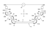
- FIG. 5 shows an example of a configuration that can be applied to the hardening of process P2.
- conductors 7A and 7B are placed on curved portions 51A and 51B, respectively, of workpiece 1a (semi-finished stabilizer) that has undergone process P1.
- first terminal 60A is attached to the end 34A of the arm portion 3A
- second terminal 60B is attached to the end 34B of the arm portion 3B.
- These terminals 60A, 60B are connected to a power source 61 that supplies alternating current.
- the frequency of the alternating current supplied by the power source 61 is not particularly limited, but as an example, a high frequency of 1 kHz or more can be used.
- the conductors 7A and 7B are electrically floating and insulated from other conductive elements such as the work 1a.
- the conductors 7A and 7B are supported by, for example, an insulating member (not shown).
- Metallic materials with excellent conductivity such as copper or aluminum can be used as the material for the conductors 7A and 7B.
- the conductors 7A and 7B may have a laminated structure of a conductive layer formed of a metallic material and an insulating layer formed of a resin or the like.
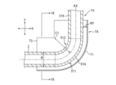
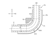
- FIG. 6 is a schematic cross-sectional view of the workpiece 1a and the conductor 7A.
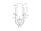
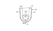
- FIG. 7 is a schematic cross-sectional view of the workpiece 1a and the conductor 7A taken along line VII-VII in FIG. 6.
- the cross-sectional view in FIG. 6 corresponds to cutting the workpiece 1a and the conductor 7A in the XY plane along the axis AX.
- the cross-sectional view in FIG. 7 corresponds to cutting the workpiece 1a and the conductor 7A in a plane perpendicular to the first direction X.
- the curved portion 51A has an outer peripheral surface 511 and an inner peripheral surface 512.
- the outer peripheral surface 511 is the portion of the surface of the workpiece 1a that is located on the outer peripheral side of the bend in the curved portion 51A.
- the inner peripheral surface 512 is the portion of the surface of the workpiece 1a that is located on the inner peripheral side of the bend in the curved portion 51A.
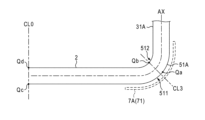
- FIG. 8 is a schematic cross-sectional view of curved portion 51A to explain outer peripheral surface 511 and inner peripheral surface 512.
- Center line CL1 shown in dashed line is a line segment passing through center of curvature C1 of curved portion 51A and axis AX.
- Another center line CL2 shown in dashed line is a line segment that is perpendicular to center line CL1 and passes through axis AX.
- Positions Q1 and Q2 shown on the surface of workpiece 1a are both points where center line CL1 intersects with the surface of workpiece 1a.
- Position Q1 is farther from center of curvature C1 than axis AX, and position Q2 is closer to center of curvature C1 than axis AX.
- Positions Q1 and Q2 each correspond to the outer shape of the cross section of curved portion 51A shown in FIG. 6.
- the outer peripheral surface 511 is the area of the surface of the workpiece 1a that includes position Q1.
- the inner peripheral surface 512 is the area of the surface of the workpiece 1a that includes position Q2.
- the surface on the position Q1 side of the center line CL2 can be defined as the outer peripheral surface 511, and the surface on the position Q2 side of the center line CL2 can be defined as the inner peripheral surface 512.
- the conductor 7A shown in Figures 6 and 7 has a first portion 71, a second portion 72, and a third portion 73.
- the boundary between the first portion 71 and the second portion 72, and the boundary between the first portion 71 and the third portion 73 are indicated by dashed lines.
- the first portion 71 faces the outer peripheral surface 511 with a gap therebetween.
- the first portion 71 is curved along the surface of the workpiece 1a.
- the second portion 72 and the third portion 73 extend from the first portion 71.
- the second portion 72 and the third portion 73 are parallel to the second direction Y, for example.
- the workpiece 1a is disposed between the second portion 72 and the third portion 73. Gaps are also formed between the second portion 72 and the workpiece 1a, and between the third portion 73 and the workpiece 1a.
- An insulating material may be disposed between the conductor 7A and the workpiece 1a.
- This insulating material may be a separate body from the conductor 7A, or may be formed integrally with the conductor 7A.
- the insulating material may be disposed in the entire space between the conductor 7A and the workpiece 1a, or may be disposed partially in the space.
- the first portion 71, the second portion 72, and the third portion 73 face not only the curved portion 51A but also the straight portions (torsion portion 2 and straight portion 31A) connected to both ends of the curved portion 51A with gaps between them.
- the conductor 7A does not have a portion that faces the inner peripheral surface 512 in the radial direction from the center of curvature C1 toward the axis AX.
- the width W1 of the gap between the first portion 71 and the workpiece 1a (the distance between the first portion 71 and the surface of the workpiece 1a) is constant overall.
- the width W2 of the gap between the second portion 72 and the workpiece 1a (the distance between the second portion 72 and the surface of the workpiece 1a) is constant overall.
- the width W3 of the gap between the third portion 73 and the workpiece 1a (the distance between the third portion 73 and the surface of the workpiece 1a) is also constant overall. Widths W1, W2, and W3 are, for example, equal, but may be different from each other.
- Widths W1, W2, and W3 are smaller than the outer diameter ⁇ of the workpiece 1a (the steel material constituting the torsion section 2, arm sections 3A, 3B, and curved sections 51A, 51B, etc.), and are preferably 1/2 or less of the outer diameter ⁇ .
- the outer diameter ⁇ is, for example, 30 mm or more. In one example, the outer diameter ⁇ is 38 mm, and the widths W1, W2, and W3 are 8 mm.
- conductor 7B are the same as those of conductor 7A.
- workpiece 1a and conductors 7A and 7B are moved relative to fixedly arranged conductors 7A and 7B, and is positioned so that the positional relationship shown in FIG. 6 and FIG. 7 is obtained.
- an alternating current is supplied from the power source 61 to a circuit including the power source 61, terminals 60A, 60B, and workpiece 1a. This causes the workpiece 1a to heat up and be hardened.
- the frequency, amplitude, and current duration of the alternating current can be determined appropriately according to the target heating temperature, etc.
- the workpiece 1a is cooled. This cooling may be natural cooling, or if rapid cooling is required, it may be performed by exposing the workpiece 1a to a liquid such as water, or by spraying a gas such as air or a liquid such as water onto the workpiece 1a.
- the skin effect increases the current density near its surface. Furthermore, in each curved portion, the current path passing near the inner surface of the bend is short, so the current density near the inner surface is likely to be high. As a result, the heating temperature near the inner surface is higher than near the outer surface. This temperature difference can be noticeable when the radius of curvature of the curved portions 51A, 51B is small, the bending angle is large, or the diameter of the workpiece 1a is large.
- conductors 7A and 7B When a current flows through a workpiece such as workpiece 1a, if an electrically floating conductor is placed nearby, the so-called proximity effect occurs. In the hardening process shown in Figure 5, this proximity effect is used to control the current density distribution (heating temperature distribution) of workpiece 1a. In other words, conductors 7A and 7B are placed in positions where the proximity effect occurs in workpiece 1a.
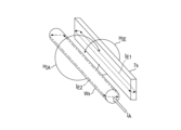
- FIG. 9 is a schematic diagram for explaining the proximity effect, showing a rod-shaped workpiece Ws and a conductor 7s disposed in its vicinity.
- a current I A from a power source flows through the workpiece Ws, a magnetic field H A is generated around the workpiece Ws (Ampere's law).
- an eddy current I E1 due to this magnetic field H IA is generated (Lenz's law). Furthermore, a magnetic field H IE due to the eddy current I E1 is generated around the conductor 7s. When this magnetic field H IE acts on the workpiece Ws, an eddy current I E2 is generated in the workpiece Ws.
- the directions of the current I A , eddy current I E1 and eddy current I E2 are as shown by the arrows in the figure. That is, in the workpiece Ws, the direction of the current I A and the direction of the eddy current I E2 are opposite in the vicinity of the side surface far from the conductor 7s. On the other hand, in the vicinity of the side surface close to the conductor 7s, the direction of the current I A and the direction of the eddy current I E2 are the same. As a result, the current density of the workpiece Ws is high in the vicinity of the side surface close to the conductor 7s. By utilizing such a proximity effect, it is possible to control the current density distribution and heating temperature distribution of the workpiece Ws.
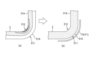
- FIG. 10 shows an example of the heating temperature distribution of the curved portion 51A when (a) AC current heating is performed without placing the conductor 7A, and when (b) AC current heating is performed with the conductor 7A placed. The darker the hatching in the figure, the higher the temperature.
- the heating temperature can be made uniform.
- FIG. 11 is a graph showing the heating temperature [°C] during quenching and the grain size number of the prior austenite grain boundary of the stabilizer 1 manufactured after this quenching.
- Experiment 1 and Analysis 1 are resistance heating using DC current
- Analyses 2 and 3 are resistance heating using AC current.
- Analysis 3 assumes the case where conductors 7A and 7B are arranged. Note that the grain size number of the prior austenite grain boundary in this embodiment can be measured by the method specified in JIS G0551.
- Figure 12 is a schematic diagram showing the measurement positions Qa, Qb, Qc, and Qd of the temperatures shown by the plots of Experiment 1 and Analysis 1-3 in Figure 11.
- Position Qa is the position where the center line CL3 of the curved portion 51A intersects with the outer peripheral surface 511.
- Position Qb is the position where the center line CL3 intersects with the inner peripheral surface 512. Note that the center line CL3 is located midway along the axis AX of the curved portion 51A and is a line segment perpendicular to the axis AX.
- Positions Qc and Qd are the positions where the center line CL0 (see Figure 2) intersects with the surface of the torsion portion 2. The center line CL0 is also a line segment perpendicular to the axis AX.
- the plot with the lowest heating temperature corresponds to position Qa
- the plot with the highest heating temperature corresponds to position Qb
- the remaining plots correspond to positions Qc and Qd.
- analysis 1 there is no temperature variation at positions Qc and Qd in the straight section (torsion section 2) due to DC current, but in the bent section (curved section 51A), current tends to flow inward, so the inner surface 512 is heated preferentially. This results in a large temperature variation at positions Qa and Qb.
- AC current heating is used in which conductors 7A and 7B are not arranged, so the area near the inner surface 512 is heated preferentially even more than in analysis 1. This results in a large temperature variation at positions Qa, Qb, Qc, and Qd.
- the temperature variation at positions Qa, Qb, Qc, and Qd is significantly reduced compared to experiment 1 and analyses 1 and 2.
- analysis 2 which does not use conductors 7A and 7B
- the plots are dispersed over a wide range with a distribution width exceeding 500°C.
- the distribution width at positions Qa, Qb, Qc, and Qd is 200°C or less. This shows that the heating temperature can be made significantly more uniform by using conductors 7A and 7B.
- the difference in grain size numbers at positions Qa, Qb, Qc, and Qd in analysis 3 is also extremely small.
- the absolute value of the difference in grain size numbers at positions Qa, Qb, Qc, and Qd is 2 or less.
- the difference in grain size numbers at positions Qa, Qb, Qc, and Qd can be further reduced.
- the shape and arrangement of conductors 7A and 7B it is possible to manufacture a stabilizer 1 in which the absolute value of the difference in grain size numbers at positions Qa, Qb, Qc, and Qd is 1 or less.
- the larger the grain size number i.e., the smaller the crystal grain size, the higher the yield strength.
- the heating temperature is significantly different between the outer peripheral surface 511 and the inner peripheral surface 512 as in Experiment 1 and Analyses 1 and 2, in order to harden the entire workpiece 1a, it is necessary to heat the area near the outer peripheral surface 511, which is less likely to be heated, to a temperature high enough to harden the entire workpiece.
- the area near the inner peripheral surface 512 which is more likely to be heated, is heated to a higher temperature than necessary, causing the crystal grain size to become coarse and the yield strength to decrease.
- heating is more than necessary, which reduces the heating efficiency.
- the heating temperature is uniform as in this embodiment (Analysis 3), it is difficult to generate parts that are heated to a higher temperature than necessary, and therefore the coarsening of the crystal grain size near the inner peripheral surface 512 is suppressed and the heating efficiency is improved.
- the workpiece 1a itself is heated, so heating efficiency is improved compared to when a heating furnace is used to heat the workpiece 1a.
- AC heating allows for more rapid heating than when a heating furnace is used, so improved heating efficiency can be expected from this standpoint as well.
- rapid heating is expected to result in finer crystal grains.
- the grain size numbers at positions Qa, Qb, Qc, and Qd in analysis 3 are all 7 or greater, and it can be seen that the crystal grains are generally finer than in analyses 1 and 2.
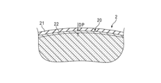
- FIG. 13 is a cross-sectional view that shows a schematic view of the vicinity of the surface layer in the torsion portion 2.
- the surface 20 of the torsion portion 2 is covered with a coating film 21.
- a decarburized layer 22 is formed near the surface 20.
- the use of AC current heating allows for rapid heating of the workpiece 1a, and therefore the generation of the decarburized layer 22 can be suppressed compared to, for example, using a heating furnace.
- the depth DP of the decarburized layer 22 from the surface 20 is 200 ⁇ m or less.
- the depth DP corresponds to the total decarburized layer depth that can be measured using the method specified in JIS G0558.
- the example in FIG. 14 differs from the example in FIG. 6 in that the width of the gap between the first portion 71 and the workpiece 1a is not constant. Specifically, the gap becomes larger the further away from the center of the curved portion 51A (the portion along the center line CL3). Thus, the gap has a minimum width W1a in the portion along the center line CL3 and a maximum width W1b at both ends facing the torsion portion 2 and the straight portion 31A.
- the width W1a is smaller than the outer diameter ⁇ of the workpiece 1a, and is preferably equal to or less than 1/2 of the outer diameter ⁇ .
- the width W1b is also smaller than the outer diameter ⁇ , but this example is not limited to this.
- the second portion 72 and the third portion 73 are not parallel.
- the second portion 72 and the third portion 73 are inclined so that the distance between them increases as they move away from the first portion 71.
- the inner surface 512 near the center of the curved portion 51A becomes hot. Furthermore, the temperature of the inner surface 512 decreases as it approaches the torsion portion 2 and the straight portion 31A.
- the configuration of the conductor 7A according to this embodiment is effective in reducing such uneven heating.
- the gap between the conductor 7A and the workpiece 1a according to the temperature distribution that can occur when AC heating is performed without using the conductor 7A, it is expected that the heating temperature can be made even more uniform.
- a third embodiment will be described.
- another example of the arrangement of conductors in AC heating is disclosed.
- the configuration other than the arrangement of the conductors can be the same as that of the first or second embodiment.
- FIG. 16 is a diagram showing an example of a configuration applicable to hardening according to the third embodiment.
- conductors 7A and 7B are arranged for curved portions 51A and 51B, respectively.
- conductors 8A and 8B are arranged for curved portions 52A and 52B, respectively, and conductors 9A and 9B are arranged for curved portions 53A and 53B, respectively.
- conductors 8A, 8B, 9A, and 9B The same configuration as conductors 7A and 7B can be applied to conductors 8A, 8B, 9A, and 9B. That is, conductors 8A and 8B have a first portion 81 that faces the outer peripheral surfaces of curved portions 52A and 52B, respectively. Conductors 9A and 9B also have a first portion 91 that faces the outer peripheral surfaces of curved portions 53A and 53B, respectively. Conductors 8A, 8B, 9A, and 9B also have portions that correspond to second portion 72 and third portion 73 of conductors 7A and 7B.
- the heating temperature and crystal grain size can be made uniform not only in curved portions 51A and 51B but also in curved portions 52A, 52B, 53A, and 53B.
- a ferromagnetic body 10 is arranged.
- the ferromagnetic body 10 can be formed of, for example, ferrite, but is not limited to this example.
- the ferromagnetic body 10 is, for example, cylindrical and extends in a direction perpendicular to the first direction X and the second direction Y, and faces the inner peripheral surface 512 via a gap.
- the gap is, for example, smaller than the outer diameter ⁇ of the workpiece 1a.
- the ferromagnetic body 10 has the function of influencing the magnetic flux generated when current is passed through the workpiece 1a, and inducing the current density to the outer peripheral surface 511.
- the heating temperature of the workpiece 1a can be controlled with greater precision. If the influence of the ferromagnetic body 10 is wider than necessary, a shield to suppress the influence of the ferromagnetic body 10 may be placed near the workpiece 1a.
- FIG. 18 is a schematic cross-sectional view showing other shapes that can be applied to the ferromagnetic body 10.
- the ferromagnetic body 10 has a sector-shaped cross-sectional shape.
- the curved surface portion of the ferromagnetic body 10 faces the inner peripheral surface 512 with a gap therebetween.
- various other shapes can be applied to the ferromagnetic body 10.
- the ferromagnetic body 10 shown in Figures 17 and 18 is also disposed near the curved portion 51B.
- the ferromagnetic body 10 may also be disposed near the other curved portions 52A, 52B, 53A, and 53B.
- FIG. 19 is a diagram showing another example of the arrangement of the ferromagnetic bodies 10.
- conductors 7A, 7B, 9A, and 9B are arranged for curved portions 51A, 51B, 53A, and 53B (first curved portions), respectively.
- ferromagnetic bodies 10A and 10B are arranged for curved portions 52A and 52B (second curved portions), respectively.
- the first parts 71 of the conductors 7A and 7B face the outer peripheral surfaces of the bends of the curved portions 51A and 51B, respectively, with a gap between them.
- the first parts 91 of the conductors 9A and 9B face the outer peripheral surfaces of the bends of the curved portions 53A and 53B, respectively, with a gap between them.
- the ferromagnetic bodies 10A and 10B face the inner peripheral surfaces of the bends of the curved portions 52A and 52B, respectively, with a gap between them.
- the workpiece 1a shown by the dashed line can be moved in the direction indicated by the arrow AR and set at the heating position. This makes it easier to position the workpiece 1a, improving the manufacturing efficiency of the stabilizer 1.
- the configuration and arrangement of the conductors and ferromagnetic materials used in the AC heating of the workpiece 1a can be modified in various ways.
- the AC heating disclosed in each embodiment can also be used for heat treatments other than hardening of the workpiece 1a.
Landscapes
- Chemical & Material Sciences (AREA)
- Engineering & Computer Science (AREA)
- Mechanical Engineering (AREA)
- Physics & Mathematics (AREA)
- Thermal Sciences (AREA)
- Crystallography & Structural Chemistry (AREA)
- Materials Engineering (AREA)
- Metallurgy (AREA)
- Organic Chemistry (AREA)
- General Induction Heating (AREA)
- Vehicle Body Suspensions (AREA)
Priority Applications (6)
| Application Number | Priority Date | Filing Date | Title |
|---|---|---|---|
| JP2025510920A JPWO2024204187A1 (https=) | 2023-03-31 | 2024-03-26 | |
| KR1020257035806A KR20250168504A (ko) | 2023-03-31 | 2024-03-26 | 스태빌라이저의 제조 방법 및 스태빌라이저 |
| CN202480019465.3A CN120882887A (zh) | 2023-03-31 | 2024-03-26 | 稳定器制造方法及稳定器 |
| EP24780299.4A EP4692380A1 (en) | 2023-03-31 | 2024-03-26 | Method for manufacturing stabilizer, and stabilizer |
| MX2025011236A MX2025011236A (es) | 2023-03-31 | 2025-09-23 | Metodo de fabricacion de estabilizador, y estabilizador |
| US19/343,453 US20260022432A1 (en) | 2023-03-31 | 2025-09-29 | Manufacturing method of stabilizer and stabilizer |
Applications Claiming Priority (2)
| Application Number | Priority Date | Filing Date | Title |
|---|---|---|---|
| JP2023-057985 | 2023-03-31 | ||
| JP2023057985 | 2023-03-31 |
Related Child Applications (1)
| Application Number | Title | Priority Date | Filing Date |
|---|---|---|---|
| US19/343,453 Continuation US20260022432A1 (en) | 2023-03-31 | 2025-09-29 | Manufacturing method of stabilizer and stabilizer |
Publications (1)
| Publication Number | Publication Date |
|---|---|
| WO2024204187A1 true WO2024204187A1 (ja) | 2024-10-03 |
Family
ID=92906655
Family Applications (1)
| Application Number | Title | Priority Date | Filing Date |
|---|---|---|---|
| PCT/JP2024/011930 Ceased WO2024204187A1 (ja) | 2023-03-31 | 2024-03-26 | スタビライザの製造方法およびスタビライザ |
Country Status (7)
| Country | Link |
|---|---|
| US (1) | US20260022432A1 (https=) |
| EP (1) | EP4692380A1 (https=) |
| JP (1) | JPWO2024204187A1 (https=) |
| KR (1) | KR20250168504A (https=) |
| CN (1) | CN120882887A (https=) |
| MX (1) | MX2025011236A (https=) |
| WO (1) | WO2024204187A1 (https=) |
Citations (10)
| Publication number | Priority date | Publication date | Assignee | Title |
|---|---|---|---|---|
| JPH01111848A (ja) * | 1987-10-26 | 1989-04-28 | Nisshin Steel Co Ltd | スタビライザーに用いられるパイプ素管 |
| JPH10297242A (ja) | 1997-04-30 | 1998-11-10 | Tube Forming:Kk | 自動車の懸架装置におけるスタビライザおよびその製造方法 |
| JPH11189022A (ja) | 1997-12-26 | 1999-07-13 | Tube Foming Co Ltd | 自動車の懸架装置におけるスタビライザおよびその製造方法 |
| JP2002331326A (ja) | 2001-03-08 | 2002-11-19 | Nhk Spring Co Ltd | 中空スタビライザおよびその製造方法 |
| WO2008111200A1 (ja) * | 2007-03-14 | 2008-09-18 | Shinko Metal Products Co., Ltd. | シームレス鋼管、シームレス鋼管を用いた中空ばねおよびその製造方法 |
| JP2012144752A (ja) * | 2011-01-06 | 2012-08-02 | Chuo Spring Co Ltd | 腐食疲労強度に優れるばね |
| JP2016084515A (ja) * | 2014-10-27 | 2016-05-19 | Jfeスチール株式会社 | ばね用鋼およびばね |
| WO2017169235A1 (ja) * | 2016-03-30 | 2017-10-05 | 日本発條株式会社 | 中空スタビライザ製造方法及び中空スタビライザ製造装置 |
| JP6258243B2 (ja) | 2015-03-23 | 2018-01-10 | 日本発條株式会社 | スタビライザおよびその製造方法 |
| EP3742865A1 (de) * | 2019-05-23 | 2020-11-25 | ITG Induktionsanlagen GmbH | Verfahren zur konduktiven erwärmung von gekrümmten metallischen werkstücken, anlage zur ausführung des verfahrens, sowie feldführungselement zur ausführung des verfahrens oder als teil der anlage |
-
2024
- 2024-03-26 KR KR1020257035806A patent/KR20250168504A/ko active Pending
- 2024-03-26 JP JP2025510920A patent/JPWO2024204187A1/ja active Pending
- 2024-03-26 CN CN202480019465.3A patent/CN120882887A/zh active Pending
- 2024-03-26 EP EP24780299.4A patent/EP4692380A1/en active Pending
- 2024-03-26 WO PCT/JP2024/011930 patent/WO2024204187A1/ja not_active Ceased
-
2025
- 2025-09-23 MX MX2025011236A patent/MX2025011236A/es unknown
- 2025-09-29 US US19/343,453 patent/US20260022432A1/en active Pending
Patent Citations (10)
| Publication number | Priority date | Publication date | Assignee | Title |
|---|---|---|---|---|
| JPH01111848A (ja) * | 1987-10-26 | 1989-04-28 | Nisshin Steel Co Ltd | スタビライザーに用いられるパイプ素管 |
| JPH10297242A (ja) | 1997-04-30 | 1998-11-10 | Tube Forming:Kk | 自動車の懸架装置におけるスタビライザおよびその製造方法 |
| JPH11189022A (ja) | 1997-12-26 | 1999-07-13 | Tube Foming Co Ltd | 自動車の懸架装置におけるスタビライザおよびその製造方法 |
| JP2002331326A (ja) | 2001-03-08 | 2002-11-19 | Nhk Spring Co Ltd | 中空スタビライザおよびその製造方法 |
| WO2008111200A1 (ja) * | 2007-03-14 | 2008-09-18 | Shinko Metal Products Co., Ltd. | シームレス鋼管、シームレス鋼管を用いた中空ばねおよびその製造方法 |
| JP2012144752A (ja) * | 2011-01-06 | 2012-08-02 | Chuo Spring Co Ltd | 腐食疲労強度に優れるばね |
| JP2016084515A (ja) * | 2014-10-27 | 2016-05-19 | Jfeスチール株式会社 | ばね用鋼およびばね |
| JP6258243B2 (ja) | 2015-03-23 | 2018-01-10 | 日本発條株式会社 | スタビライザおよびその製造方法 |
| WO2017169235A1 (ja) * | 2016-03-30 | 2017-10-05 | 日本発條株式会社 | 中空スタビライザ製造方法及び中空スタビライザ製造装置 |
| EP3742865A1 (de) * | 2019-05-23 | 2020-11-25 | ITG Induktionsanlagen GmbH | Verfahren zur konduktiven erwärmung von gekrümmten metallischen werkstücken, anlage zur ausführung des verfahrens, sowie feldführungselement zur ausführung des verfahrens oder als teil der anlage |
Also Published As
| Publication number | Publication date |
|---|---|
| JPWO2024204187A1 (https=) | 2024-10-03 |
| KR20250168504A (ko) | 2025-12-02 |
| CN120882887A (zh) | 2025-10-31 |
| MX2025011236A (es) | 2025-10-01 |
| EP4692380A1 (en) | 2026-02-11 |
| US20260022432A1 (en) | 2026-01-22 |
Similar Documents
| Publication | Publication Date | Title |
|---|---|---|
| US7525073B2 (en) | Transverse flux electric inductors | |
| JP3061648B2 (ja) | 誘導硬化装置 | |
| EP2900036B1 (en) | High-frequency induction heating device and processing device | |
| WO2024204187A1 (ja) | スタビライザの製造方法およびスタビライザ | |
| JP2012515430A (ja) | 複雑形状の加工品の誘導加熱処理 | |
| CA3287582A1 (en) | Method for manufacturing stabilizer, and stabilizer | |
| US20250230850A1 (en) | Coil spring, suspension device, and coil spring manufacturing method | |
| JP5390868B2 (ja) | 誘導加熱コイル | |
| JP4332551B2 (ja) | 複雑な形状の加工品の誘電加熱処理 | |
| EP3011063B1 (en) | Inductor for single-shot induction heating of complex workpieces | |
| WO2024142977A1 (ja) | コイルばねおよびその製造方法 | |
| JP7746605B2 (ja) | 交流通電加熱方法および交流通電加熱装置 | |
| JP5481100B2 (ja) | 誘導加熱コイル、誘導加熱装置及び部品製造装置 | |
| US20240237158A9 (en) | Induction heating device and method for heating stabilizers | |
| JPS62280325A (ja) | 長い導電性工作片を周辺誘導電流によつて熱処理する方法及びその為の装置 | |
| WO2025134521A1 (ja) | コイルばね、懸架装置およびコイルばねの製造方法 | |
| WO2024204183A1 (ja) | コイルばねの製造方法 | |
| EP4589030A1 (en) | Mobile hardening method and mobile hardening device | |
| JP2008150661A (ja) | 焼戻用加熱コイル | |
| JP4963947B2 (ja) | 薄板製部材の熱処理方法および装置 | |
| JP3824779B2 (ja) | 高周波焼入方法及び誘導加熱コイル | |
| JPH01184234A (ja) | 高疲労強度コイルばねの製造方法 | |
| CN115866819A (zh) | 热处理装置以及热处理方法 | |
| WO2025203949A1 (ja) | コイルばね、懸架装置およびコイルばねの製造方法 | |
| JP3106815B2 (ja) | 高周波焼入コイル |
Legal Events
| Date | Code | Title | Description |
|---|---|---|---|
| 121 | Ep: the epo has been informed by wipo that ep was designated in this application |
Ref document number: 24780299 Country of ref document: EP Kind code of ref document: A1 |
|
| ENP | Entry into the national phase |
Ref document number: 2025510920 Country of ref document: JP Kind code of ref document: A |
|
| WWE | Wipo information: entry into national phase |
Ref document number: 2025510920 Country of ref document: JP |
|
| WWE | Wipo information: entry into national phase |
Ref document number: 202480019465.3 Country of ref document: CN |
|
| WWE | Wipo information: entry into national phase |
Ref document number: 2501006322 Country of ref document: TH |
|
| ENP | Entry into the national phase |
Ref document number: 1020257035806 Country of ref document: KR Free format text: ST27 STATUS EVENT CODE: A-0-1-A10-A15-NAP-PA0105 (AS PROVIDED BY THE NATIONAL OFFICE) |
|
| WWE | Wipo information: entry into national phase |
Ref document number: KR1020257035806 Country of ref document: KR Ref document number: 202517103394 Country of ref document: IN |
|
| WWE | Wipo information: entry into national phase |
Ref document number: 2024780299 Country of ref document: EP |
|
| WWP | Wipo information: published in national office |
Ref document number: 202480019465.3 Country of ref document: CN |
|
| NENP | Non-entry into the national phase |
Ref country code: DE |
|
| ENP | Entry into the national phase |
Ref document number: 2024780299 Country of ref document: EP Effective date: 20251031 |
|
| ENP | Entry into the national phase |
Ref document number: 2024780299 Country of ref document: EP Effective date: 20251031 |
|
| ENP | Entry into the national phase |
Ref document number: 2024780299 Country of ref document: EP Effective date: 20251031 |
|
| ENP | Entry into the national phase |
Ref document number: 2024780299 Country of ref document: EP Effective date: 20251031 |
|
| WWP | Wipo information: published in national office |
Ref document number: 202517103394 Country of ref document: IN |
|
| ENP | Entry into the national phase |
Ref document number: 2024780299 Country of ref document: EP Effective date: 20251031 |
|
| ENP | Entry into the national phase |
Ref document number: 2024780299 Country of ref document: EP Effective date: 20251031 |
|
| ENP | Entry into the national phase |
Ref document number: 2024780299 Country of ref document: EP Effective date: 20251031 |
|
| ENP | Entry into the national phase |
Ref document number: 2024780299 Country of ref document: EP Effective date: 20251031 |
|
| WWP | Wipo information: published in national office |
Ref document number: 2024780299 Country of ref document: EP |