WO2024201835A1 - ロボット制御装置及びロボット制御システム - Google Patents
ロボット制御装置及びロボット制御システム Download PDFInfo
- Publication number
- WO2024201835A1 WO2024201835A1 PCT/JP2023/012943 JP2023012943W WO2024201835A1 WO 2024201835 A1 WO2024201835 A1 WO 2024201835A1 JP 2023012943 W JP2023012943 W JP 2023012943W WO 2024201835 A1 WO2024201835 A1 WO 2024201835A1
- Authority
- WO
- WIPO (PCT)
- Prior art keywords
- variable
- value
- processor
- robot
- unit
- Prior art date
- Legal status (The legal status is an assumption and is not a legal conclusion. Google has not performed a legal analysis and makes no representation as to the accuracy of the status listed.)
- Ceased
Links
Images









Classifications
-
- B—PERFORMING OPERATIONS; TRANSPORTING
- B25—HAND TOOLS; PORTABLE POWER-DRIVEN TOOLS; MANIPULATORS
- B25J—MANIPULATORS; CHAMBERS PROVIDED WITH MANIPULATION DEVICES
- B25J9/00—Program-controlled manipulators
- B25J9/16—Program controls
- B25J9/1674—Program controls characterised by safety, monitoring, diagnostic
Definitions
- This disclosure relates to a robot control device and a robot control system.
- robot program commands have the function of communicating with CNC (computerized numerical control) industrial machines and accessing CNC setting variables. By obtaining or writing setting variables with these commands, the robot or robot control device and the CNC industrial machines can confirm and request each other's status.
- Access to variables for CNC settings requires the execution of an access command in the robot program. For this reason, the CNC industrial machine cannot make requests to the robot or robot control device at any time, but must wait until the access command is executed in the robot or robot control device. For the same reason, it is difficult for the robot or robot control device and the industrial machine to monitor each other's status. To make requests at any time and monitor the other's status, it is possible to synchronize the robot and CNC industrial machine. In order to synchronize the robot and CNC industrial machine, multiple signals must be prepared. However, CNC variables are usually 8-byte or 16-byte variables. For this reason, if the robot or robot control device obtains one variable to monitor the status of one of the CNC industrial machines, the amount of communication data becomes enormous and the communication cycle becomes slow.
- the problem that the embodiments of the present disclosure aim to solve is to provide a robot control device and a robot control system that can periodically read (acquire) or write variables for setting industrial machines and use them as variable data for the robot.
- the robot control device of the embodiment includes an acquisition unit, a storage unit, and an allocation memory unit.
- the acquisition unit repeatedly acquires variable values from an industrial machine.
- the storage unit writes the variable values acquired by the acquisition unit to a storage area that stores the variable values.
- the allocation memory unit stores allocation data indicating the location or address of the storage area to which the variable is written.
- This disclosure enables a robot control device to read (acquire) or write variables of industrial machinery and use them in the same way as variable data of a robot.
- FIG. 1 is a block diagram showing an example of a main configuration of a control system according to an embodiment and components included in the control system.
- 1 is a block diagram showing an example of main functions and main configurations of a control system according to an embodiment
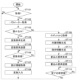
- 4 is a flowchart showing an example of processing according to the first embodiment performed by a processor of the control device in FIG. 1 .
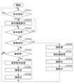
- 4 is a flowchart showing an example of processing according to the first and second embodiments by a processor of the industrial machine in FIG. 1 .
- 4 is a flowchart showing an example of processing according to the first and second embodiments by a processor of the control device in FIG. 1 .
- 4 is a flowchart showing an example of processing according to the first and second embodiments by a processor of the teaching device in FIG.
- the processor 110 functions as, for example, an allocation unit 111, a data conversion unit 112, a startup unit 113, a stop unit 114, and a target unit 115.
- the starting unit 113 starts the robot 300 .
- the stopping unit 114 stops the robot 300 .
- the RAM 130 includes, for example, two types of memory areas: a memory area 131 and an IO memory area 132.
- the memory area 131 is a memory area for storing data other than IO data.
- the IO memory area 132 is a memory area for storing IO data, and is a memory area capable of storing IO data. The IO data will be described later.
- the memory area 131 and the IO memory area 132 may be physically present on the same memory, or may be physically present on different memories. However, in the first embodiment, the RAM 130 does not need to include the IO memory area 132.
- a storage device other than the RAM 130 such as the ROM 120 or the auxiliary storage device 140 , may include the IO memory area 132 .
- the RAM 130 is also allocated a startup area 133 and an alarm area 134.
- the startup area 133 and the alarm area 134 will be described later.
- the auxiliary storage device 140 is an auxiliary storage device of a computer with the processor 110 at its core.
- the auxiliary storage device 140 is, for example, an EEPROM (electrical erasable programmable read-only memory), a HDD (hard disk drive), or flash memory.
- the auxiliary storage device 140 stores, for example, system software and application software from among the above programs.
- the auxiliary storage device 140 also stores data used by the processor 110 in performing various processes, data generated by the processes in the processor 110, various setting values, etc.
- the auxiliary storage device 140 and the like also store parameter information, allocation information and first execution information, which will be described later.
- the allocation information and first execution information may be stored in a device other than the control device 100.
- the parameter information is information that stores, for example, at least one of settings related to obtaining the setting variables 241 from the industrial machine 200 and settings related to writing the setting variables 241 to the industrial machine 200.
- the value of each setting in the parameter information is set, for example, by a user, administrator, or designer of the control system 1. A default value may be set for each setting in the parameter information.
- the value of each setting in the parameter information may be changeable or unchangeable.
- the auxiliary storage device 140 may store multiple pieces of parameter information.
- the control interface is an interface through which the control device 100 communicates with the robot 300.
- the control device 100 controls the robot 300 by communicating with the robot 300 via the control interface 150.
- the communication interface 160 is an interface through which the control device 100 communicates with the industrial machine 200, the teaching device 400, and the like.
- the communication interface 160 communicates, for example, via a network.
- the communication interface 160 communicates without using a network.
- the network is, for example, a communication network including a LAN (local area network) or the Internet.
- the control device 100 communicates with the industrial machine 200, the teaching device 400, and the like via the communication interface 160.
- Bus 170 includes a control bus, an address bus, a data bus, etc., and transmits signals exchanged between each part of the control device 100.
- the industrial machine 200 is, for example, a machine tool or a peripheral device of a machine tool. Alternatively, the industrial machine 200 may be some other machine.
- the control method of the industrial machine 200 is CNC. Alternatively, the control method of the industrial machine 200 may be NC or some other method.
- the industrial machine 200 includes, as an example, a processor 210, a ROM 220, a RAM 230, an auxiliary storage device 240, a communication interface 250, an input device 260, and a display device 270.
- a bus 280 and the like connect these various parts.
- the processor 210 is the central part of the computer that performs calculations and control processes necessary for the operation of the industrial machine 200, and performs various calculations and processes.
- the processor 210 is, for example, a CPU, MPU, SoC, DSP, GPU, ASIC, PLD, or FPGA. Alternatively, the processor 210 is a combination of two or more of these. The processor 210 may also be a combination of these with a hardware accelerator or the like.
- the processor 210 controls each part to realize various functions of the industrial machine 200 based on programs such as firmware, system software, and application software stored in the ROM 220 or the auxiliary storage device 240.
- the processor 210 also executes processes described below based on the programs. A part or all of the programs may be incorporated into the circuitry of the processor 210.
- the ROM 220 and the RAM 230 are main memory devices of the computer with the processor 210 at its core.
- the ROM 220 is a non-volatile memory used exclusively for reading data.
- the ROM 220 stores, for example, firmware among the above programs.
- the ROM 220 also stores data used by the processor 210 when performing various processes.
- the RAM 230 is a memory used for reading and writing data.
- the RAM 230 is used as a work area for storing data that is temporarily used when the processor 210 performs various processes.
- the RAM 230 is typically a volatile memory.
- the auxiliary storage device 240 is an auxiliary storage device of a computer with the processor 210 at its core.
- the auxiliary storage device 240 is, for example, an EEPROM, a HDD, or a flash memory.
- the auxiliary storage device 240 stores, for example, system software and application software from among the above programs.
- the auxiliary storage device 240 also stores data used by the processor 210 when performing various processes, data generated by the processes in the processor 210, various setting values, etc.
- the auxiliary storage device 240 or RAM 230 stores the setting variables 241.
- the user of the industrial machine 200 can change the values of the setting variables 241.
- the setting variables 241 determine various settings of the industrial machine 200 or the control system 1.
- the setting variables 241 behave like global variables or external variables, for example.
- the auxiliary storage device 240 or RAM 230 may store multiple setting variables 241.
- One setting variable 241 may include multiple values. In this case, each of the multiple values determines a setting.
- the setting variables 241 are shown as being stored in the auxiliary storage device 240 as an example.
- the above programs include, for example, an industrial machine program 242 and a ladder program 243.
- the industrial machine program 242 and the ladder program 243 are described as being stored in the auxiliary storage device 240 as an example.
- the industrial machine program 242 is, for example, a program for the industrial machine 200 to perform processing and is created by an end user.
- the ladder program 245 performs, for example, processing for operating the industrial machine 200 and for linking with external devices.
- the input device 260 accepts operations by an operator of the industrial machine 200.
- the input device 260 is, for example, a keyboard, a keypad, a touchpad, a mouse, or a controller.
- the input device 260 may also be a device for voice input.
- the bus 280 includes a control bus, an address bus, a data bus, etc., and transmits signals exchanged between each part of the industrial machine 200.
- the processor 410 is the central part of the computer that performs the calculations and control processes necessary for the operation of the teaching device 400, and performs various calculations and processes.
- the processor 410 is, for example, a CPU, MPU, SoC, DSP, GPU, ASIC, PLD, or FPGA. Alternatively, the processor 410 is a combination of two or more of these. The processor 410 may also be a combination of these with a hardware accelerator.
- the processor 410 controls each part to realize various functions of the teaching device 400 based on programs such as firmware, system software, and application software stored in the ROM 420 or the auxiliary storage device 440.
- the processor 410 also executes the processes described below based on the programs. Note that a part or all of the programs may be incorporated into the circuitry of the processor 410.
- the auxiliary storage device 440 is an auxiliary storage device of a computer with the processor 410 at its core.
- the auxiliary storage device 440 is, for example, an EEPROM, a HDD, or a flash memory.
- the auxiliary storage device 440 stores, for example, system software and application software among the above programs.
- the auxiliary storage device 440 also stores data used by the processor 410 when performing various processes, data generated by the processes in the processor 410, various setting values, etc.
- the communication interface 450 is an interface through which the teaching device 400 communicates with the control device 100 and the like.
- the communication interface 450 communicates, for example, via the network described above. Alternatively, the communication interface 450 communicates without using a network.
- the teaching device 400 communicates with the control device 100 and the like via the communication interface 450.
- the input device 460 accepts operations by an operator of the teaching device 400.
- the input device 460 is, for example, a keyboard, a keypad, a touchpad, a mouse, or a controller.
- the input device 460 may also be a device for voice input.
- the display device 470 displays a screen for notifying the operator of the teaching device 400 of various information.
- the display device 470 is, for example, a display such as a liquid crystal display or an organic EL display.
- a touch panel can also be used as the input device 460 and the display device 470. That is, the display panel of the touch panel can be used as the display device 470, and the pointing device of the touch panel that allows touch input can be used as the input device 460.
- the bus 480 includes a control bus, an address bus, a data bus, etc., and transmits signals exchanged between each part of the teaching device 400.
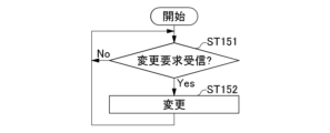
- FIGs. 3, 5, and 7 are flowcharts showing an example of the process by the processor 110 of the control device 100.
- the processor 110 executes the processes of Figs. 3, 5, and 7 based on a program stored in, for example, the ROM 120 or the auxiliary storage device 140.
- Figs. 4 and 8 are flowcharts showing an example of the process by the processor 210 of the industrial machine 200.
- the processor 210 executes the process of Fig.
- Fig. 6 is a flowchart showing an example of the process by the processor 410 of the teaching device 400.
- the processor 410 executes the process of Fig. 6 based on a program stored in, for example, the ROM 420 or the auxiliary storage device 440.
- the processor 110 of the control device 100 executes, for example, the processes of FIG. 3, FIG. 5, and FIG. 7 in parallel or in parallel.
- the processor 210 of the industrial machine 200 executes, for example, the processes of FIG. 4 and FIG. 8 in parallel or in parallel.
- the processor 110 of the control device 100 determines whether or not to acquire parameter information.
- the processor 110 determines, for example, to acquire parameter information at every predetermined time TP.
- the processor 110 determines to acquire parameter information when the current time is after the predetermined time CT.
- the processor 110 determines to acquire parameter information when an input instructing the processor 110 to acquire parameter information is received.
- the input instructing the processor 110 to acquire parameter information is, for example, an input from a program executed by the control device 100.
- the input instructing the processor 110 to acquire parameter information may be an input from outside the control device 100.
- the processor 110 determines, for each piece of parameter information, whether or not to acquire the parameter information. Alternatively, if the processor 110 determines to acquire the parameter information, it determines which parameter information to acquire.
- the processor 110 may use a different time TP for each piece of parameter information to be acquired.
- the processor 110 determines that the parameter information is to be acquired when the time TP corresponding to the parameter information has elapsed since the acquisition of the parameter information. Note that the time PT corresponding to the parameter information is, for example, included in the parameter information.
- first parameter information and second parameter information.
- the time TP corresponding to the first parameter information is time TP1.
- the first parameter information includes time TP1.
- the time TP corresponding to the second parameter information is time TP2.
- the second parameter information includes time TP2.
- the processor 110 determines to acquire the first parameter information. If the time elapsed since the second parameter information was last acquired is equal to or greater than time TP2, the processor 110 determines to acquire the second parameter information.
- the processor 110 may use a different time CT for each piece of parameter information acquired.
- step ST101 determines No in step ST101 and repeats the processing of step ST101.
- the processor 110 determines Yes in step ST101 and proceeds to step ST102.
- step ST102 the processor 110 acquires parameter information from the auxiliary storage device 140 or the like. If there is a plurality of pieces of parameter information, the processor 110 acquires, for example, the parameter information determined to be acquired in step ST101.
- step ST103 the processor 110 determines whether to acquire the setting variables 241 from the industrial machine 200.
- the parameter information includes, for example, information indicating whether to acquire the setting variables 241 from the industrial machine 200 or to write the setting variables 241 to the industrial machine 200 (hereinafter referred to as "setting information").
- the processor 110 determines whether to acquire the setting variables 241 from the industrial machine 200 by referring to the setting information. If the processor 110 determines to acquire the setting variables 241 from the industrial machine 200, it determines Yes in step ST103 and proceeds to step ST104.
- the parameter information includes the setting information. Therefore, in step ST101, determining whether to acquire parameter information indicating that the setting variables 241 are to be acquired from the industrial machine 200 can also be said to be determining whether to acquire the setting variables 241 from the industrial machine 200. Also, in step ST101, determining whether to acquire parameter information indicating that the setting variables 241 are to be written to the industrial machine 200 can also be said to be determining whether to write the setting variables 241 to the industrial machine 200.
- step ST104 the processor 110 generates a variable request.
- the variable request is information that requests the industrial machine 200 to transmit the setting variables 241.
- the variable request may also include designation information that designates the setting variables 241 to be transmitted.
- the processor 110 acquires the designation information from, for example, the parameter information acquired in step ST102.
- the processor 110 then generates a variable request that includes the designation information.
- step ST105 the processor 110 instructs the communication interface 160 to send a variable request to the industrial machine 200.
- the communication interface 160 Upon receiving this instruction to send, the communication interface 160 sends the variable request to the industrial machine 200.
- the sent variable request is received by the communication interface 250 of the industrial machine 200.
- step ST121 of FIG. 4 the processor 210 of the industrial machine 200 determines whether or not a variable request has been received by the communication interface 250. If a variable request has not been received, the processor 210 determines No in step ST121 and proceeds to step ST122.
- step ST122 the processor 210 determines whether or not a write request has been received by the communication interface 250. If a write request has not been received, the processor 210 determines No in step ST122 and returns to step ST121. Thus, the processor 210 goes into a standby state in which steps ST121 and ST122 are repeated until a variable request or a write request is received.
- processor 210 If the processor 210 receives a variable request while in a standby state in which it repeats steps ST121 and ST122, it determines Yes in step ST121 and proceeds to step ST123.
- step ST123 the processor 210 acquires the setting variables 241 from the auxiliary storage device 240 or the RAM 230.
- the processor 210 acquires, for example, the setting variables 241 targeted by the specification information included in the variable request received in step ST121. Alternatively, the processor 210 may acquire all of the setting variables 241.
- step ST124 the processor 210 generates a variable response.
- the variable response is information that includes the setting variables 241 acquired in step ST123.
- step ST125 the processor 210 instructs the communication interface 160 to transmit the variable response generated in step ST124 to the industrial machine 200 that sent the variable request.
- the communication interface 160 Upon receiving this transmission instruction, transmits the variable response to the industrial machine 200.
- the transmitted variable response is received by the communication interface 250 of the industrial machine 200.
- the processor 210 returns to step ST121.
- step ST106 of FIG. 3 the processor 110 of the control device 100 waits for a variable response to be received by the communication interface 250. If a variable response is received, the processor 110 judges Yes in step ST106 and proceeds to step ST107.
- the processor 110 acquires allocation information from the auxiliary storage device 140 or the like.
- the allocation information stores information about the monitored variables.
- the monitored variables are the setting variables 241 or variables for inputting the values of the setting variables 241.
- the monitored variables are variables that may be subject to monitoring in the process shown in FIG. 5.
- the processor 110 allocates the monitored variables to the RAM 130 or the like, for example, when starting the processes shown in FIG. 3 and FIG. 5 or when the control device 100 is started.
- the auxiliary storage device 140 may store the setting variables 241.
- the number of monitored variables may be one or more.
- the allocation information includes information indicating which monitoring variable each setting variable 241 is to be stored in.
- the allocation information includes information indicating which part of which monitoring variable each setting variable 241 is to be stored in.
- the allocation information defines which monitoring variable is to be stored in, for example, by the address of a storage area such as the RAM 130 to which the monitoring variable is assigned or the auxiliary storage device 140 that stores the monitoring variable.
- the allocation information includes information indicating which address of the storage area each setting variable 241 is to be stored in.
- the allocation information defines which monitoring variable is to be stored in, for example, by the variable name.
- the variable name is an example of the location of the storage area where the setting variable 241 is stored.
- the allocation information may also define the storage area of multiple monitoring variables by one address.
- the allocation information defines the storage area by the address of the beginning of the multiple monitoring variables and the length from the beginning to the end of the multiple monitoring variables. Note that the multiple monitoring variables are assumed to be consecutively arranged in the storage area.
- RAM 230 or auxiliary storage device 240 is an example of a storage area that stores the values of variables.
- the area that stores monitored variables is an example of a storage area that stores the values of variables. Therefore, the allocation information is an example of assignment data that indicates the location or address of the storage area where the values of the variables are stored.
- the allocation information is an example of assignment data that stores the location or address of the storage area that stores the values of the multiple variables.
- allocation information that defines the storage areas for multiple monitored variables by one address is an example of assignment data that stores one address that indicates the storage area that stores the values of the multiple variables.
- the auxiliary storage device 140 that stores the allocation information is an example of an assignment memory unit that stores the assignment data.
- step ST108 the processor 110 inputs (stores) (writes) the setting variable 241 received in step ST106 into the monitoring variable indicated by the allocation information. If the allocation information indicates which address the setting variable 241 is to be stored in, the processor 110 inputs (stores) the setting variable 241 into the address indicated in the allocation information. After processing step ST108, the processor 110 returns to step ST101. As described above, the processor 110 repeats steps ST101 to ST108. As a result, the processor 110 repeatedly acquires the setting variable 241 from the industrial machine 200 periodically or irregularly, and inputs it into the monitoring variable.
- the processor 110 functions as an example of a storage unit that writes the value of the variable acquired by the acquisition unit into a storage area that stores the value of the variable.
- the processor 110 does not have to perform the process of step ST101. In this case, the processor 110 starts the process shown in FIG. 3 from step ST102. Then, after the process of step ST108, the processor 110 returns to step ST102. In this case, the processor 110 repeatedly acquires the setting variable 241 from the industrial machine 200 by repeating steps ST102 to ST108 without going through the judgment of step ST101.
- the processor 110 functions as an example of an acquisition unit that repeatedly acquires variable values from the industrial machine by executing the processes of steps ST101 to ST108 in FIG. 3.
- step ST131 of FIG. 5 the processor 110 of the control device 100 checks each monitored variable. That is, the processor 110 obtains the value of each monitored variable.
- step ST132 processor 110 determines whether the value of each monitored variable has changed since it was last acquired. If the value of any monitored variable has changed since it was last acquired, processor 110 determines Yes in step ST132 and proceeds to step ST133. On the other hand, if the value of any monitored variable has not changed since it was last acquired, processor 110 determines No in step ST132 and proceeds to step ST134.
- step ST133 the processor 110 generates a display request.
- the display request includes the monitored variables or the values of the monitored variables.
- the display request is information that requests the teaching device 400 to display the values of the monitored variables.
- the processor 110 instructs the communication interface 160 to transmit the display request to the industrial machine 200.
- the communication interface 160 Upon receiving this transmission instruction, transmits the display request to the industrial machine 200.
- the transmitted display request is received by the communication interface 450 of the industrial machine 200.
- the processor 410 of the teaching device 400 that receives the display request displays the monitored variable screen on the display device 470.
- the monitored variable screen includes, for example, an image showing the value of the monitored variable whose value has been changed.
- step ST141 of FIG. 6 the processor 410 of the teaching device 400 determines whether or not a display request has been received by the communication interface 450. If a display request has not been received, the processor 410 determines No in step ST141 and proceeds to step ST142.
- processor 410 determines whether or not to change the value of the variable.
- Processor 410 determines that the value of the variable is to be changed when, for example, an operational input is made to instruct the change of the value of the variable displayed on input device 460. If processor 410 does not determine that the value of the variable is to be changed, it determines No in step ST142 and returns to step ST141. Thus, processor 410 enters a standby state in which it repeats steps ST141 and ST142 until a display request is received or it is determined that the value of the variable is to be changed.
- step ST141 If a display request is received while in a standby state in which steps ST141 and ST142 are repeated, the processor 410 determines Yes in step ST141 and proceeds to step ST143.
- step ST143 the processor 410 generates an image corresponding to the variable screen.
- the processor 410 then instructs the display device 470 to display this generated image.
- the display device 470 displays the variable screen.
- FIG. 9 is a diagram showing an example of a variable screen SC1a displayed on the display device 470.
- the variable screen is a screen that includes the values of the monitoring variables included in the display request.
- the variable screen allows an operation to instruct the user to change the displayed variable values.
- the variable screen also allows an operation to instruct how the variable values are to be changed.
- the operator of the teaching device 400 can give these instructions by, for example, operating the input device 460.
- the variable screen SC1a includes an area AR1 as an example.
- Area AR1 shows the numerical value of each variable.
- Data [1] through Data [16] show the numbers assigned to each variable. However, in the state shown in Figure 9, only variables Data [1] and Data [2] exist. Variables Data [3] through Data [16] are unused or do not exist.
- Each of the variables displayed in area AR1 can be selected using the input device 460 or the like.
- each variable displayed in area AR1 can be changed using input device 460 or the like.
- processor 410 determines in step ST142 of FIG. 6 that the value of the variable is to be changed.
- the change information described below includes the content of the change in value caused by the operation.
- step ST143 the processor 410 returns to step ST141.
- step ST143 the processor 410 functions as an example of a display unit that cooperates with the display device 470 to display the value of the variable.
- step ST142 determines Yes in step ST142 and proceeds to step ST144.
- step ST144 the processor 410 generates a change request.
- the change request includes change information indicating the content of the change to the variable.
- the change request is information that instructs the control device 100 to change the value of the monitored variable in accordance with the change information.
- the processor 410 instructs the communication interface 450 to send the change request to the control device 100.
- the communication interface 450 sends the change request to the control device 100.
- the sent change request is received by the communication interface 160 of the control device 100.
- the processor 410 returns to step ST141.
- the processor 410 functions as an example of a change unit that changes the value of a variable by executing the processing of step ST144.
- step ST151 of FIG. 7 the processor 110 of the control device 100 waits for a change request to be received by the communication interface 160. If a change request is received, the processor 110 judges Yes in step ST151 and proceeds to step ST152.
- step ST152 the processor 110 changes the value of the monitored variable according to the change information in the change request received in step ST151. After processing step ST152, the processor 110 returns to step ST151.
- the processor 110 acquires first execution information from the auxiliary storage device 140 or the like.
- the first execution information stores, for each monitored variable, what processing is executed when the monitored variable reaches a certain value.
- the first execution information stores, for example, information identifying the monitored variable, the value, and information indicating the processing to be executed in association with each other.
- the first execution information indicates that the associated processing is executed when the value of the monitored variable reaches the associated value.
- the first execution information stores that the robot 300 is started when the monitoring variable stored in the start-up area 133 becomes a predetermined value.
- the first execution information stores that the robot 300 is stopped when the monitoring variable stored in the alarm area 134 becomes a predetermined value. Note that the monitoring variable stored in the alarm area 134 indicates that an alarm has occurred in the industrial machine 200 when the value of the monitoring variable becomes the predetermined value.
- step ST135 processor 110 determines whether or not to execute a process corresponding to the value of setting variable 241. That is, for example, for each monitored variable, if the value is the associated value in the first execution information, processor 110 determines to execute a process associated with that monitored variable and that value in the first execution information. If processor 110 does not determine to execute the process, it determines No in step ST135 and returns to step ST131. On the other hand, if processor 110 determines to execute the process, it determines Yes in step ST135 and proceeds to step ST136.
- step ST136 processor 110 executes the processing determined to be executed in step ST135. After processing in step ST136, processor 110 returns to step ST131.
- processor 110 monitors the monitored variable, and executes the specified processing when the value of the monitored variable becomes a predetermined value.
- processor 110 inputs the value of setting variable 241 to the monitored variable by the processing in FIG. 3. Therefore, processor 110 monitors the setting variable by the processing in FIG. 3 and FIG. 5, and executes the specified processing when the value of the setting variable becomes a predetermined value.
- the monitoring variable in this example is a monitoring variable that stores a setting variable 241 indicating that an alarm has occurred in the industrial machine 200 and the content of the alarm.
- the predetermined value in this example is a value indicating that an alarm has occurred, for example 1.
- the predetermined process in this example is stopping the robot 300.
- the stopping unit 114 stops the robot 300. If the processor 110 determines in step ST134 that the value of the monitoring variable in this example has become 1, it stops the robot 300 in step ST135. The processor 110 stops the robot 300, for example, by stopping the robot program.
- the predetermined process include starting the robot 300, causing the robot 300 to perform a predetermined operation, executing various robot programs, and the control device 100 executing a predetermined process.
- the processor 110 starts the robot 300, for example, by executing a robot program that includes a start command.
- the start unit 113 starts the robot 300.
- the predetermined value may be a range.
- the predetermined value may be 1 to 3.
- the processor 110 executes the predetermined process when the value of the monitored variable is between 1 and 3.
- predetermined values there may be multiple predetermined values. And there may be multiple predetermined processes. For example, suppose there are two predetermined values, a first predetermined value and a second predetermined value. And there are two predetermined processes, a first predetermined process and a second predetermined process. And the process corresponding to the first predetermined value is the first predetermined process, and the process corresponding to the second predetermined value is the second predetermined process.
- the processor 110 executes the first predetermined process when the value of the monitored variable is the first predetermined value. And the processor 110 executes the second predetermined process when the value of the monitored variable is the second predetermined value.
- the value of the monitored variable and the specified value are not limited to being numeric.
- the value of the monitored variable and the specified value may be, for example, a character string, a date, a Boolean type, a pointer, an object, or a structure.
- the specified value may be a value indicating the absence of a value, such as null or nothing.
- the specified processing will be further explained using FIG. 10.
- the value of a certain setting variable 241 (hereinafter referred to as the "target variable") changes when the industrial machine 200 performs a certain action or when a certain operation is performed on the industrial machine 200 (hereinafter referred to as the "value change trigger").
- the control system 1 can cause the control device 100 to perform some specified processing in response to the value change trigger.
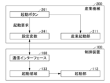
- FIG. 10 Such an example will be explained using FIG. 10.
- FIG. 10 is a block diagram for explaining an example of the operation of the control device 100 and the industrial machine 200.
- the industrial machine 200 is provided with, for example, a start button 261 as an input device 260.
- the start button 261 is a button for starting and stopping the industrial machine 200.
- the start button 261 When the start button 261 is operated while the industrial machine 200 is stopped, the industrial machine 200 starts and begins operation.
- the start button 261 When the start button 261 is operated while the industrial machine 200 is operating, the industrial machine 200 stops.
- the start button 261 When the start button 261 is operated while the industrial machine 200 is stopped, it outputs a start request signal.
- the start button 261 When the start button 261 is operated while the industrial machine 200 is operating, it outputs a stop request signal.
- the processor 210 receives input of the start request signal and the stop request signal.
- the processor 210 When the processor 210 receives a start request signal, it changes the value of the setting variable 241 (target variable) to a value indicating that the industrial machinery 200 is operating. Conversely, when the processor 210 receives a stop request signal, it changes the value of the target variable to a value indicating that the industrial machinery 200 is stopped.
- the operation of the start button 261 acts as a value change trigger, changing the value of this target variable.
- the input of a start request signal or a stop request signal acts as a value change trigger, changing the value of this target variable.
- the processor 210 also functions as an industrial startup unit 211 by executing a program stored in the ROM 220 or the auxiliary storage device 240.
- the industrial startup unit 211 starts an industrial machinery program 242 in order to operate the industrial machinery 200 in response to the operation of the startup button 261.
- the processor 110 of the control device 100 acquires the target variable via the communication interface 160, as described in the explanation of Figs. 3 and 4.
- the control device 100 stores the acquired target variable or the value of the target variable in the start-up area 133 as a monitored variable.
- the processor 110 monitors the change in the value of the target variable by monitoring the start-up area 133.
- the processor 11 performs a predetermined process, for example, starting the robot 300.
- the start-up unit 113 performs the startup.
- the processor 11 performs a predetermined process, for example, stopping the robot 300.
- the stop unit 114 performs the stop.
- the operation of the start button 261 starts or stops not only the industrial machine 200 but also the robot 300.
- the processor 110 functions as an example of an execution unit that executes a predetermined process corresponding to a predetermined value when the value of the variable written to the storage area is a predetermined value.
- the processor 110 determines No in step ST103 in FIG. 3 and proceeds to step ST109.
- step ST109 the processor 110 acquires the instruction variable.
- the instruction variable is a variable that indicates the write content indicated by the instruction information described below.
- the processor 110 uses the acquisition information in the parameter information acquired in step ST102 to determine which variable to acquire as the instruction variable.
- the acquisition information is information that defines which variable to acquire as the instruction variable.
- the processor 110 acquires the instruction variable, for example, from the memory area of the robot 300. Alternatively, the processor 110 may acquire the instruction variable from the RAM 130 or the auxiliary storage device 140, or an external device.
- the value of the instruction variable is an example of a value stored in the storage area. Therefore, by executing the process of step ST109, the processor 110 functions as an example of a robot variable acquisition unit that acquires the value stored in the storage area.
- the processor 110 In step ST110, the processor 110 generates target information.
- the target information is information indicating the write target.
- the write target indicates, for example, which setting variable 241 is the target to which a value is to be written (stored).
- the target information indicates the write target or the position of the write target, for example, by a variable name or address.
- the processor 110 determines the write target, for example, by using the target determination information in the parameter information acquired in step ST102.
- the target determination information is information that determines which setting variable 241 is the target to which a value is to be written.
- the target determination information determines the setting variable 241, for example, by a variable name or address.
- the target determination information is an example of allocation data that indicates the variable of the industrial machine 200 that stores the value acquired by the robot variable acquisition unit.
- the auxiliary storage device 140 that stores the target determination information is also an example of an allocation storage unit that stores the allocation data.
- step ST111 the processor 110 generates instruction information.
- the instruction information is information indicating the contents to be written to the setting variable 241.
- the contents to be written indicated by the instruction information is, for example, the value of the instruction variable acquired in step ST109.
- the target information is an example of variable designation data indicating the variable of the industrial machine to which the value is to be written.
- step ST112 the processor 110 generates a write request.
- the write request includes the target information generated in step ST110 and the instruction information generated in step ST111.
- the write request is information that instructs the industrial machine 200 to write the content indicated in the instruction information to the target indicated in the target information.
- step ST113 the processor 110 instructs the communication interface 160 to transmit the write request generated in step ST112 to the industrial machinery 200.
- the communication interface 160 Upon receiving this transmission instruction, transmits the write request to the industrial machinery 200.
- the transmitted write request is received by the communication interface 250 of the industrial machinery 200.
- step ST122 determines Yes in step ST122 and proceeds to step ST126.
- step ST126 the processor 210 writes the value indicated by the instruction information to the setting variable 241 to be written, which is stored in the auxiliary storage device 240 or RAM 230, etc., in accordance with the write request received in step ST122. If the value indicated by the instruction information differs from the value of the setting variable 241 to be written, the processor 210 changes the value by overwriting the value. However, if the value indicated by the instruction information and the value of the setting variable 241 to be written are the same, the processor 210 does not need to overwrite.
- step ST127 the processor 210 generates a completion response.
- the completion response is information indicating that writing of the value based on the write request has been completed.
- step ST1208 the processor 210 instructs the communication interface 250 to transmit the completion response generated in step ST127 to the control device 100 that sent the write request. Upon receiving this instruction to transmit, the communication interface 250 transmits the completion response to the control device 100. The transmitted completion response is received by the communication interface 160 of the control device 100. After processing step ST128, the processor 210 returns to step ST121.
- step ST114 of FIG. 3 the processor 110 of the control device 100 waits for a write request to be received by the communication interface 160. If a write request is received, the processor 110 determines Yes in step ST114 and returns to step ST101.
- the processor 110 repeats steps ST101 to ST103 and steps ST109 to ST114. As a result, the processor 110 repeatedly transmits write requests to the industrial machine 200 on a regular or irregular basis.
- the processor 110 functions as an example of a transmission unit that periodically and repeatedly transmits to the industrial machine the value acquired by the robot variable acquisition unit and variable designation data indicating the variable of the industrial machine to which the value is to be written, by working together with the communication interface 250 to execute the processing of step ST112.
- the processor 110 functions as an example of a transmission unit by executing the processing of step ST112.
- step ST161 of FIG. 8 the processor 210 of the industrial machine 200 checks the values of each setting variable 241 by referring to the auxiliary storage device 240 or the RAM 230, etc.
- step ST162 the processor 210 determines whether or not to execute processing according to the value of each setting variable 241. For example, when the value of the setting variable 241 is a predetermined value that is set for each setting variable 241, the processor 110 determines that the processing is to be executed. If the processor 210 does not execute the processing, the processor 210 determines No in step ST162 and returns to step ST161. On the other hand, if the processor 210 executes the processing, the processor 210 determines Yes in step ST162 and proceeds to step ST163.
- step ST163 the processor 210 executes a predetermined process corresponding to the predetermined value. After the process of step ST163, the processor 210 returns to step ST161. As described above, the processor 210 monitors the setting variable 241 by the process of FIG. 8, and executes the predetermined process when the value of the setting variable 241 becomes a predetermined value.
- the control device 100 repeatedly reads (acquires) the setting variables 241 from the industrial machine 200. This allows the control device 100 to monitor the setting variables of the industrial machine 200. Furthermore, by acquiring the setting variables 241, the control device 100 can use the setting variables 241 as variables of the robot. Furthermore, when adding a signal to a conventional CNC industrial machine, it is necessary to add processing for the added signal to the ladder program. However, end users of CNC industrial machines usually cannot change the ladder program. Therefore, end users request the industrial machine manufacturer or the like to change the ladder program. This results in a large amount of work being required to change the ladder program. On the other hand, the setting variables 241 can be referenced in the machining program without the need to change the ladder program.
- the control device 100 uses allocation information that stores one location or one address that indicates an assigned memory area for storing the values of multiple variables. This allows the control device 100 to store multiple setting variables 241 together.
- the control device 100 executes a corresponding predetermined process when the setting variable 241 acquired from the industrial machine 200 is a predetermined value. This allows the industrial machine 200 to operate the control device 100 and the robot 300 using the setting variable 241.
- the predetermined process is to execute or stop a robot program. Therefore, in the control system 1 of the first embodiment, the industrial machine 200 can execute or stop a robot program.
- the control device 100 stops the robot 300 based on the value of the setting variable 241 indicating that an alarm has occurred. Therefore, the control device 100 of the first embodiment can stop the robot 300 when an abnormality occurs in the control device 100, for example.
- the control device 100 repeatedly acquires the instruction variable and transmits a write request to the industrial machine 200. This allows the control device 100 to rewrite the setting variable 241 of the industrial machine 200 when the value of the instruction variable changes. Therefore, the control device 100 can operate the industrial machine 200 using the instruction variable.
- the teaching device 400 changes the value of the setting variable 241.
- the control system 1 of the first embodiment allows the setting variable 241 to be manually rewritten.
- control device 100 converts the setting variables 241 into IO (input/output) data and stores the data in the IO memory area. Also, the control system 1 of the second embodiment differs from the first embodiment in that the instruction variables are IO data and are stored in an IO memory area.
- the configuration of the control system 1 of the second embodiment is similar to that of the first embodiment, and therefore a description thereof will be omitted.
- the auxiliary storage device 140 and the like store IO memory information, which will be described later, instead of the allocation information.
- the auxiliary storage device 140 and the like store second execution information, which will be described later, instead of the first execution information.
- FIG 11 is a flowchart showing an example of processing by the processor 210 of the industrial machine 200.
- the processor 210 executes the processing of Figure 11 based on a program stored in, for example, the ROM 220 or the auxiliary storage device 240.
- Figure 13 is a flowchart showing an example of processing by the processor 410 of the teaching device 400.
- the processor 410 executes the processing of Figure 13 based on a program stored in, for example, the ROM 420 or the auxiliary storage device 440.
- the processor 110 of the control device 100 executes the processes shown in Figures 5, 7, and 11.
- the processor 110 executes, for example, the processes of Figures 5, 7, and 11 in parallel or in parallel.
- the processor 210 of the industrial machine 200 executes the processes shown in Figures 4 and 8, similar to the first embodiment.
- the processor 410 of the teaching device 400 executes the processes shown in Figures 6 and 13. Descriptions of operations in the second embodiment that are similar to those in the first embodiment will be omitted.
- the processor 210 of the industrial machine 200 transmits the setting variable 241 as floating-point data in ST125 of FIG. 4.
- the processor 210 converts the setting variable 241 to floating-point data and transmits it.
- the processor 210 transmits the setting variable 241 stored in floating-point data.
- the industrial machine 200 uses a 32-bit floating-point data type or a 64-bit double-precision floating-point data type as the floating-point data type. In the case of a double-precision floating-point data type, a total of 64 bits are arranged from the beginning in the following order: 1 bit for the sign part, 11 bits for the exponent part, and 52 bits for the mantissa part.
- Each setting variable 241 is normally 1 bit. By storing the value of each setting variable 241 in each bit of the floating-point type, 64 1-bit setting variable 241 values can be stored in the case of double-precision floating-point type data. In the case of n-bit floating-point type data, n 1-bit setting variable 241 values can be stored. Note that n is a positive number.
- the industrial machine 200 can also use a setting variable 241 of 2 or more bits.
- the setting variable 241 is m bits
- the value of the setting variable 241 is stored using m bits of floating-point data.
- m is an integer of 2 or more.
- the auxiliary storage device 140 of the control device 100 and the auxiliary storage device 240 of the industrial machine 200 store bit information.
- the bit information is data that defines which bit of the floating-point data stores which value of the setting variable 241.
- the processor 210 of the industrial machine 200 uses the bit information to convert the setting variable 241 into floating-point data.
- the processor 210 uses the bit information to store the setting variable 241 in the auxiliary storage device 240 or RAM 230, etc., in the form of floating-point data.
- step ST106 of FIG. 11 if the processor 110 of the control device 100 judges Yes in step ST106 of FIG. 11, it proceeds to step ST201.
- step ST201 the processor 110 converts the setting variable 241 received in step ST106 into IO data.
- IO data is a sequence of multiple binary data values such as “0” and “1", “ON” and “OFF”, or "True” and “False”. Therefore, IO data is data like an array of Boolean variables. Binary data values can also be seen as 1-bit binary data.
- the processor 110 converts the setting variable 241 into IO data. Two methods for converting into IO data are shown below: (i) and (ii).
- each bit of a variable expressed in binary is used as IO.
- the received setting variable 241 is floating-point data, which is a variable expressed in binary. Therefore, the processor 110 uses the value of each bit of the floating-point data as is as IO data. For example, if the first four digits of the floating-point data are "0100", the first digit of the IO data is "0”, the second digit is “1”, the third digit is "0”, and the fourth digit is "0".
- Conversion method 2 is a method in which the absolute value of a positive number obtained by rounding off the decimal point of the value of the setting variable 241 is extracted, converted to binary, and used as IO. For example, assume that the number expressed in decimal of the floating-point type data before conversion is "-1234.567". In this case, the processor 110 rounds off the decimal point of "-1234.567” to "-1234". Then, the processor 110 obtains the absolute value of this value. Here, the absolute value is "1234". Furthermore, the processor 110 converts this absolute value into binary integer type data. Here, the value converted to binary is, for example, "0000 0100 1101 0011” if it is 16 bits.
- the processor 110 uses each bit of this value as IO data. With this value, the first IO data will be “0”, the second will be “0”, the third will be “0”, the fourth will be “0”, the fifth will be “0”, the sixth will be “1”, the seventh will be “0”, and so on.
- the configuration variable 241 is a floating-point type, it may not be possible to manipulate it bit by bit.
- conversion method 1 is used to manipulate only specific IOs of the control device 100 from the processor 210, the user must calculate the floating-point type when manipulating a specific bit, which is time-consuming.
- Conversion method 2 has the effect of reducing this time-consuming work, in exchange for the amount of data communicated being reduced.
- the processor 110 functions as an example of an IO conversion unit that converts the value of the variable acquired by the acquisition unit into IO data.
- the processor 110 acquires IO memory information.
- the IO memory information stores information about the IO memory area 132.
- the IO memory information includes information indicating where in the IO memory area 132 the value of which setting variable 241 is to be stored.
- the IO memory information indicates where the value of each setting variable 241 is to be stored, for example, by storing at which address in the IO memory area 132 the first piece of converted IO data is to be stored. For example, if the address at which the first piece of IO data is stored is X, the address at which the second piece of IO data is to be stored is X+1.
- the IO memory information may also include information indicating which setting variable 241 is to be stored at each address.
- the IO memory information is an example of allocation data.
- step ST203 the processor 110 stores the IO data converted in step ST201 at the address indicated by the IO memory information in the IO memory area 132.
- the IO memory area 132 stores the setting variable 241 in each bit.
- the processor 110 returns to step ST201.
- the IO memory area 132 is an example of a storage area for storing the value of a variable.
- the area of the IO memory area 132 for storing the value of the setting variable 241 is an example of a storage area for storing the value of a variable.
- the processor 110 functions as an example of an acquisition unit that repeatedly acquires variable values from the industrial machine by executing the process of FIG. 11.
- the processor 110 uses the configuration variables 241 stored in the IO memory area 132 instead of the monitoring variables in the process of FIG. 5.
- the processor 110 uses the second execution information instead of the first execution information in the processing of steps ST134 to ST136.
- the second execution information stores, for example, for each address of the IO memory area 132, what processing is executed when what value is reached.
- the second execution information stores, for example, the address of the IO memory area 132, the value, and information indicating the processing to be executed in association with each other.
- the second execution information indicates that the associated predetermined processing is executed when the value of the address of the IO memory area 132 becomes the associated value.
- the second execution information may also be capable of storing what processing is executed when each of the values of the addresses of the multiple IO memory areas 132 becomes a predetermined value determined for each address. For example, the second execution information may be capable of storing that a predetermined processing is executed when the value of a certain address Y1 is 1 and the value of a certain address Y2 is 0.
- step ST135 for example, if the value stored in each address of the IO memory area 132 is a value associated in the second execution information, the processor 110 determines to execute a process associated with that address and that value in the second execution information. As described above, the processor 110 monitors the values stored in each address of the IO memory area 132, and executes the specified process when the value becomes a predetermined value. As described above, the processor 110 inputs the value of the setting variable 241 to the IO memory area 132 by the process of FIG. 11. Therefore, the processor 110 monitors the setting variable 241 by the process of FIG. 11 and FIG. 5, and executes the specified process when the value of the setting variable 241 becomes a predetermined value.
- the change request is information that instructs the control device 100 to change the value of the setting variable 241 stored in the IO memory area 132 according to the change information.
- the processor 110 of the control device 100 changes the value of the setting variable 241 stored in the IO memory area 132 according to the change information in the received change request.
- FIG. 12 is a diagram showing an example of a variable screen SC1b displayed on the display device 470.
- the variable screen SC1b is a variable screen that displays (ii) the setting variables 241 converted by conversion method 2.
- the variable screen SC1b includes an area AR2, as an example.
- Area AR2 shows the value of each bit of the variable in binary representation.
- the variable in binary representation shown in area AR2 is a variable in binary representation converted using (ii) conversion method 2 of data [1].
- data [1] each bit is used as an area for setting.
- data [1] is viewed as a 32-bit floating-point number, it becomes the number 21.123.
- conversion method 2 is "21" in decimal and "0000 0000 0001 0101" in binary.
- only the lowest 16 digits of the binary number are shown here. The highest 16 digits are all zero.
- the value of each bit displayed in area AR2 can be changed using input device 460 or the like.
- processor 410 determines that the value of the variable is to be changed in step ST142 of FIG. 6.
- the change information includes the content of the change in value caused by the operation.
- the processor 110 changes the setting variables 241 stored in the IO memory area 132 instead of the monitoring variables.
- step ST135 the processor 110 determines to execute processing according to the value of the setting variable 241 if the value of the setting variable 241 stored in the IO memory area 132 is a predetermined value.
- the teaching device 400 can also display a screen for checking and editing the robot program (hereinafter referred to as the "editing screen").
- the editing screen and the processing related to the editing screen will be described with reference to FIG. 13.
- the processor 410 of the teaching device 400 starts the processing shown in FIG. 13 in response to, for example, receiving an instruction to display the editing screen.
- step ST211 of FIG. 13 the processor 410 of the teaching device 400 waits for the designation of a robot program to be edited.
- the operator of the teaching device 400 performs an operation to designate the robot program to be edited. If the processor 410 receives the designation of the robot program to be edited, it judges Yes in step ST211 and proceeds to step ST212.
- step ST212 the processor 410 of the teaching device 400 generates an image corresponding to the editing screen SC2 as shown in FIG. 14.
- the processor 410 then instructs the teaching device 400 to display the generated image.
- the processor 410 of the teaching device 400 Upon receiving the display instruction, the processor 410 of the teaching device 400 causes the display device 470 to display the editing screen SC2.
- FIG. 14 is a diagram showing an example of the editing screen SC2.
- the editing screen SC2 is a screen for editing a robot program.
- the editing screen SC2 includes an area AR10 and an area AR20.
- Area AR10 is an area that displays the program to be edited. Area AR10 displays the program using one or more images IM11. Each image IM1 shows an instruction in the program. Image IM1 shows the content of the instruction using, for example, a pictogram. Area AR10 may also display each instruction using text, etc. Using area AR10, it is possible to add, change, and delete instructions.
- area AR10 can be operated to specify the command to be edited.
- each image IM1 is a button.
- the command corresponding to the operated image IM1 becomes the target for editing. Note that if no command is specified as the target for editing, for example, the first command automatically becomes the target for editing.
- Area AR20 is an area for editing the command to be edited.
- the command to be edited is displayed in area AR20.
- Area AR20 includes areas AR21 to AR25, as an example. Note that area AR20 may include areas different from areas AR21 to AR25, depending on the command to be edited.
- Area AR21 is an area that displays the command to be edited.
- "DO [1]” is displayed as the command.
- "DO [1]” is an output command. Note that the "1" part is a number displayed in area AR22.
- Area AR22 is an area for specifying the setting variable 241 for which a value change or the like is to be performed.
- the target setting variable 241 can be specified by inputting a number, address, variable name, or the like indicating the setting variable 241 into area AR22.
- the "setting variable 241 specified as the target for which a value change or the like is to be performed" is hereinafter referred to as the "specified variable.”
- Area AR22 also displays a number, address, variable name, or the like that identifies the specified setting variable 241.
- Area AR23 is an area for changing the value of a specified variable.
- the value of the specified variable can be changed by inputting a value into area AR23.
- Area AR23 also displays the current value of the specified variable.
- Area AR24 displays the current value of data (hereinafter referred to as "change data") whose value will be changed when the command displayed in area AR21 is executed.
- the change data is, for example, an instruction variable. Therefore, the change data is stored, for example, in a memory area of the robot 300.
- Area AR25 displays the value of the changed data after the command is executed.
- processor 410 determines whether or not to change the command to be edited. For example, if an operation has been performed to instruct a change to the command to be edited, processor 410 determines that the command to be edited is to be changed. If processor 410 does not determine that the command to be edited is to be changed, processor 410 determines No in step ST213 and proceeds to step ST214.
- step ST214 processor 410 determines whether or not an operation to designate a designated variable has been performed. For example, the input to area AR22 described above is an operation to designate a designated variable. If an operation to designate a designated variable has not been performed, processor 410 determines No in step ST214 and proceeds to step ST215.
- step ST215 processor 410 determines whether an operation has been performed to instruct a change in the value of the designated variable. For example, inputting a value into area AR23 described above is an operation that instructs a change in value. If an operation that instructs a change in the value of the designated variable has not been performed, processor 410 determines No in step ST215 and returns to step ST214. Thus, processor 410 enters a standby state in which steps ST213 to ST215 are repeated until it is determined that the command to be edited is to be changed, an operation that specifies a designated variable is performed, or an operation that instructs a change in the value of the designated variable is performed.
- processor 410 determines that the command to be edited is to be changed while in a standby state in which steps ST213 to ST215 are repeated, it determines Yes in step ST213 and returns to step ST212. Then, processor 410 updates the display of editing screen SC1 in the processing of step ST212 to a screen corresponding to the changed command to be edited.
- processor 410 determines Yes in step ST214 and proceeds to step ST216.
- step ST216 the processor 410 obtains the value of the specified variable from the RAM 130 of the control device 100, etc.
- step ST217 the processor 410 obtains the current value of the change data.
- step ST218 the processor 410 uses the current values of the specified variables to calculate the value of the changed data after the command to be edited is executed.
- step ST219 processor 410 displays the value acquired in step ST217 in area AR24.
- processor 410 also displays the value calculated in step ST218 in area AR25.
- processor 410 returns to step ST212.
- processor 410 determines Yes in step ST215 and proceeds to step ST220.
- step ST220 the processor 410 generates a change request.
- the change request includes change information indicating the content of the change to the variable.
- the change request is information that instructs the control device 100 to change the value of the setting variable 241 stored in the IO memory area 132 in accordance with the change information.
- the change information includes a number or address that identifies the specified variable and the changed value of the specified variable.
- the changed value is the value specified by the operation that instructs the change of the value of the specified variable.
- the change request is the same as step ST144 in FIG. 6.
- the processor 410 instructs the communication interface 450 to transmit the change request to the industrial machine 200.
- the communication interface 450 transmits the change request to the industrial machine 200.
- the transmitted change request is received by the communication interface 450 of the industrial machine 200.
- the processor 410 functions as an example of a change unit that changes the values of the variables in response to editing of the robot program.
- step ST221 the processor 410 uses the changed value of the specified variable to calculate the value of the changed data after the command to be edited is executed.
- step ST222 processor 410 displays the value calculated in step ST221 in area AR25. After processing step ST222, processor 410 returns to step ST214.
- the processor 410 functions as an example of an editing unit that edits a robot program for controlling a robot by executing the process shown in FIG. 13.
- step ST103 if the processor 110 of the control device 100 determines No in step ST103, it proceeds to step ST204.
- step ST204 the processor 110 obtains a value indicating the written content of the setting variable 241 from the IO memory area 132 of the RAM 130.
- the value is, for example, an indicator variable in the form of binary IO data. Note that the value has been converted into IO data, for example, by a method similar to that of step ST201.
- the processor 110 converts the indicator variable into IO data by a method similar to that of step ST201 and stores it in the IO memory area 132.
- step ST205 the processor 110 converts the value acquired in step ST204 from binary IO data to a data format before conversion to IO data.
- the data format before conversion is the same as the data format of the setting variable 241.
- the data format before conversion is, for example, a decimal numeric value.
- the data format of the setting variable 241 is not usually IO data.
- the processor 110 functions as an example of a conversion unit that converts the value acquired by the robot variable acquisition unit into a data format other than IO data.
- step ST206 the processor 110 generates a write request.
- the write request includes target information and instruction information, as in the second embodiment. However, the write content indicated by the instruction information indicates the value converted in step ST205.
- the processor 110 instructs the communication interface 160 to transmit the write request to the industrial machine 200. Upon receiving this transmission instruction, the communication interface 160 transmits the write request to the industrial machine 200. The transmitted write request is received by the communication interface 250 of the industrial machine 200. After processing step ST206, the processor 110 returns to step ST201.
- the processor 210 rewrites the setting variable 241 in accordance with the write request, as in the second embodiment.
- control system 1 of the second embodiment provides the same effects as the second embodiment.
- the control device 100 converts the setting variables 241 into IO data. If a signal with a pre-assigned purpose is prepared to perform a specific process, such as externally executing or stopping a robot program, it can be operated with 1-bit data, the data size is small, and the system is easy to read. Furthermore, by using 1-bit data, the amount of data communication can be reduced compared to transmitting numerical data.
- control device 100 uses each bit of a variable expressed in binary as IO. This allows the control device 100 to include multiple settings in one numerical value.
- control device 100 has an IO memory area 132. Therefore, the control device 100 can store the instruction variables as IO data.
- the teaching device 400 changes the value of the setting variable 241 in response to editing of the robot program.
- the control system 1 of the second embodiment is capable of editing the robot program in a manner that involves changing the value of the setting variable 241.
- the above embodiment can be modified as follows.
- the control system of the embodiment may include, instead of the teaching device 400, a display device that does not have a function for creating a robot program.
- some or all of the processing performed by the teaching device 400 may be performed by the control device 100 or the robot 300.
- the control device of the embodiment may include some or all of the configuration of the teaching device 400.
- Processor 110, processor 210, and processor 410 may implement some or all of the processing implemented by programs in the above embodiments through a hardware circuit configuration.
- the program that realizes the processing of the embodiment is transferred, for example, in a state stored in a non-transitory storage medium within the device.
- the device may be transferred without the program stored therein.
- the program may then be transferred separately and written to the device.
- the program may be transferred, for example, by recording it on a removable, non-transitory storage medium, or by downloading it via a network such as the Internet or a LAN.
- Control system 100 Control device 110, 210, 410 Processor 111 Allocation unit 112 Data conversion unit 113 Start unit 114 Stop unit 115 Target unit 120, 220, 420 ROM 130,230,430 RAM 131 Memory area 132 IO memory area 133 Start area 134 Alarm area 140, 240, 440 Auxiliary storage device 150 Control interface 160, 250, 450 Communication interface 170, 280, 480 Bus 200 Industrial machine 211 Industrial start section 241 Setting variable 242 Industrial machine program 243 Ladder program 260, 460 Input device 261 Start button 270, 470 Display device 300 Robot 400 Teaching device
Landscapes
- Engineering & Computer Science (AREA)
- Robotics (AREA)
- Mechanical Engineering (AREA)
- Numerical Control (AREA)
- Manipulator (AREA)
- Programmable Controllers (AREA)
Abstract
Description
また、ロボットプログラムの命令にはCNC(computerized numerical control)産業機械と通信してCNCの設定用の変数にアクセスする機能がある。この命令で設定用の変数を取得又は書き込みすることで、ロボット又はロボット制御装置とCNC産業機械とは、互いに相手の状態確認及び要求ができる。
〔第1実施形態〕
実施形態に係る制御システム1について図1及び図2を用いて説明する。
図1は、実施形態に係る制御システム1及び制御システム1に含まれる構成要素の要部構成の一例を示すブロック図である。図2は、実施形態に係る制御システム1の要部機能及び要部構成の一例を示すブロック図である。
制御システム1は、ロボット300の制御などを行うシステムである。制御システム1は、一例として、制御装置100、産業機械200、ロボット300及び教示装置400を含む。制御システム1は、ロボット制御システムの一例である。
データ変換部112は、設定変数241をIOデータに変換する。設定変数241については後述する。
停止部114は、ロボット300を停止する。
ROM120は、専らデータの読み出しに用いられる不揮発性メモリである。ROM120は、上記のプログラムのうち、例えばファームウェアなどを記憶する。また、ROM120は、プロセッサー110が各種の処理を行う上で使用するデータなども記憶する。なお、ROM120は、複数のメモリによって構成されていても良い。
なお、RAM130に代えて、ROM120又は補助記憶装置140などのRAM130以外の記憶装置がIOメモリ領域132を備えていても良い。
ROM220は、専らデータの読み出しに用いられる不揮発性メモリである。ROM220は、上記のプログラムのうち、例えばファームウェアなどを記憶する。また、ROM220は、プロセッサー210が各種の処理を行う上で使用するデータなども記憶する。
RAM230は、データの読み書きに用いられるメモリである。RAM230は、プロセッサー210が各種の処理を行う上で一時的に使用するデータを記憶するワークエリアなどとして利用される。RAM230は、典型的には揮発性メモリである。
産業機械プログラム242は、例えば、産業機械200が加工するためのプログラムでありエンドユーザーが作成する。ラダープログラム245は、例えば、産業機械200を操作するため、また外部機器との連携をとるための処理をおこなう。
ROM420は、専らデータの読み出しに用いられる不揮発性メモリである。ROM420は、上記のプログラムのうち、例えばファームウェアなどを記憶する。また、ROM420は、プロセッサー410が各種の処理を行う上で使用するデータなども記憶する。
RAM430は、データの読み書きに用いられるメモリである。RAM430は、プロセッサー410が各種の処理を行う上で一時的に使用するデータを記憶するワークエリアなどとして利用される。RAM430は、典型的には揮発性メモリである。
産業機械200のプロセッサー210は、例えば、図4及び図8の処理を並行又は並列で実行する。
第1実行情報は、一例として、起動領域133に記憶された監視変数が所定の値になった場合にロボット300を起動することを記憶する。第1実行情報は、一例として、アラーム領域134に記憶された監視変数が所定の値になった場合にロボット300を停止することを記憶する。なお、アラーム領域134に記憶される監視変数は、値が当該所定の値である場合に産業機械200においてアラームが発生したことを示す。
指示変数の値は、格納領域に格納されている値の一例である。したがって、プロセッサー110は、ステップST109の処理を実行することで、格納領域に格納されている値を取得するロボット変数取得部の一例として機能する。
第2実施形態の制御システム1では、第1実施形態とは異なり、制御装置100は設定変数241をIO(input/output)データに変換してIOメモリ領域に記憶する。
また、第2実施形態の制御システム1は、第1実施形態とは異なり、指示変数がIOデータである。また、指示変数は、IOメモリ領域に記憶されている。
第2実施形態の制御システム1の構成は第1実施形態と同様であるので説明を省略する。
変換方法1では、バイナリ表現の変数の各ビットをIOとして使用する。受信した設定変数241はバイナリ表現の変数である浮動小数点型のデータである。このため、プロセッサー110は、浮動小数点型の各ビットの値をそのまま用いてIOデータとする。例えば、浮動小数点型のデータの先頭4桁が「0100」である場合、IOデータの1つ目は「0」、2つ目は「1」、3つ目は「0」、4つ目は「0」である。
変換方法2は、設定変数241の値の小数点以下を四捨五入した正数の絶対値を取り出し、バイナリに変換してIOとして使用する方法である。変換前の浮動小数点型のデータを10進数で表した数が例えば「-1234.567」であるとする。この場合、プロセッサー110は、「-1234.567」の小数点以下を四捨五入して「-1234」とする。そして、プロセッサー110は、この値の絶対値を求める。ここでは、絶対値は、「1234」である。さらに、プロセッサー110は、この絶対値を2進数の整数型のデータに変換する。ここでは、2進数に変換された値は、一例として16ビットであれば「0000 0100 1101 0011」である。プロセッサー110は、この値の各ビットを、IOデータとして用いる。この値であれば、IOデータの1つ目は「0」、2つ目は「0」、3つ目は「0」、4つ目は「0」、5つ目は「0」、6つ目は「1」、7つ目は「0」…である。
なお、IOメモリ領域132は、変数の値を記憶する格納領域の一例である。また、IOメモリ領域132のうち、設定変数241の値を格納する領域は、変数の値を記憶する格納領域の一例である。
実施形態の制御システムは、教示装置400に代えて、ロボットプログラムを作成する機能を備えない表示装置を含んでも良い。
100 制御装置
110,210,410 プロセッサー
111 割付部
112 データ変換部
113 起動部
114 停止部
115 対象部
120,220,420 ROM
130,230,430 RAM
131 メモリ領域
132 IOメモリ領域
133 起動領域
134 アラーム領域
140,240,440 補助記憶装置
150 制御インターフェース
160,250,450 通信インターフェース
170,280,480 バス
200 産業機械
211 産業起動部
241 設定変数
242 産業機械プログラム
243 ラダープログラム
260,460 入力デバイス
261 起動ボタン
270,470 表示デバイス
300 ロボット
400 教示装置
Claims (11)
- 産業機械から変数の値を繰り返し取得する取得部と、
前記取得部によって取得された前記変数の値を、前記変数の値を格納する格納領域に書き込む格納部と、
前記変数を書き込む、前記格納領域の箇所又はアドレスを示す割り当てデータを記憶する割り当て記憶部と、を備えるロボット制御装置。 - 前記取得部によって取得された前記変数の値をIOデータに変換するIO変換部をさらに備え、
前記格納部は、前記IO変換部によって変換された前記変数の値を前記格納領域に書き込み、
前記格納領域は、IOメモリ領域内にある、請求項1に記載のロボット制御装置。 - 前記取得部は、複数の前記変数の値を繰り返し取得し、
前記割り当て記憶部は、複数の前記変数の値を格納する前記格納領域の1つの前記箇所又は1つの前記アドレスを示す前記割り当てデータを記憶し、
前記格納部は、前記割り当てデータに基づき、複数の前記変数の値を前記格納領域に書き込む、請求項2に記載のロボット制御装置。 - 前記格納領域に書き込まれた前記変数の値が所定の値である場合、前記所定の値に対応した所定の処理を実行する実行部をさらに備える、請求項1に記載のロボット制御装置。
- 前記所定の処理は、ロボットプログラムの実行又は停止である、請求項4に記載のロボット制御装置。
- 前記変数は、アラームが発生したことを示し、
前記所定の処理は、ロボットの停止である、請求項4に記載のロボット制御装置。 - 格納領域に格納されている値を取得するロボット変数取得部と、
前記ロボット変数取得部によって取得される値を格納する産業機械の変数を示した割り当てデータを記憶する割り当て記憶部と、
前記ロボット変数取得部によって取得された値と、前記値を書き込む前記産業機械の変数を示す変数指定データとを、前記産業機械に周期的に繰り返し送信する送信部と、を備える、ロボット制御装置。 - 前記格納領域は、IOメモリ領域であり、
前記格納領域に記憶された値は、IOデータであり、
前記ロボット変数取得部は、前記IOデータを取得し、
前記ロボット変数取得部によって取得された値をIOデータ以外のデータ形式に変換する変換部をさらに備え、
前記送信部は、前記変換部によって変換された値を前記産業機械に送信する、請求項7に記載のロボット制御装置。 - ロボット制御装置及び表示装置を含み、
前記ロボット制御装置は、
産業機械から変数の値を繰り返し取得する取得部と、
前記取得部によって取得された前記変数の値を、前記変数の値を格納する格納領域に書き込む格納部と、
前記変数を書き込む、前記格納領域の箇所又はアドレスを示す割り当てデータを記憶する割り当て記憶部と、を備え、
前記表示装置は、前記変数の値を表示する表示部を備える、ロボット制御システム。 - 前記表示装置は、前記変数の値を変更する変更部をさらに備える、請求項9に記載のロボット制御システム。
- 前記表示装置は、
ロボットを制御するためのロボットプログラムを編集する編集部と、
前記ロボットプログラムの編集に応じて前記変数の値を変更する変更部と、をさらに備える、請求項9に記載のロボット制御システム。
Priority Applications (5)
| Application Number | Priority Date | Filing Date | Title |
|---|---|---|---|
| CN202380095971.6A CN120883155A (zh) | 2023-03-29 | 2023-03-29 | 机器人控制装置以及机器人控制系统 |
| JP2023543023A JP7534552B1 (ja) | 2023-03-29 | 2023-03-29 | ロボット制御装置及びロボット制御システム |
| DE112023005683.8T DE112023005683T5 (de) | 2023-03-29 | 2023-03-29 | Roboter-Steuerungsvorrichtung und Roboter-Steuerungssystem |
| PCT/JP2023/012943 WO2024201835A1 (ja) | 2023-03-29 | 2023-03-29 | ロボット制御装置及びロボット制御システム |
| TW113108665A TW202438264A (zh) | 2023-03-29 | 2024-03-08 | 機器人控制裝置及機器人控制系統 |
Applications Claiming Priority (1)
| Application Number | Priority Date | Filing Date | Title |
|---|---|---|---|
| PCT/JP2023/012943 WO2024201835A1 (ja) | 2023-03-29 | 2023-03-29 | ロボット制御装置及びロボット制御システム |
Publications (1)
| Publication Number | Publication Date |
|---|---|
| WO2024201835A1 true WO2024201835A1 (ja) | 2024-10-03 |
Family
ID=92261450
Family Applications (1)
| Application Number | Title | Priority Date | Filing Date |
|---|---|---|---|
| PCT/JP2023/012943 Ceased WO2024201835A1 (ja) | 2023-03-29 | 2023-03-29 | ロボット制御装置及びロボット制御システム |
Country Status (5)
| Country | Link |
|---|---|
| JP (1) | JP7534552B1 (ja) |
| CN (1) | CN120883155A (ja) |
| DE (1) | DE112023005683T5 (ja) |
| TW (1) | TW202438264A (ja) |
| WO (1) | WO2024201835A1 (ja) |
Citations (2)
| Publication number | Priority date | Publication date | Assignee | Title |
|---|---|---|---|---|
| WO2020144772A1 (ja) * | 2019-01-09 | 2020-07-16 | 三菱電機株式会社 | 数値制御装置および数値制御方法 |
| WO2022097719A1 (ja) * | 2020-11-09 | 2022-05-12 | ファナック株式会社 | 数値制御システム及び産業機械の制御方法 |
-
2023
- 2023-03-29 CN CN202380095971.6A patent/CN120883155A/zh active Pending
- 2023-03-29 JP JP2023543023A patent/JP7534552B1/ja active Active
- 2023-03-29 DE DE112023005683.8T patent/DE112023005683T5/de active Pending
- 2023-03-29 WO PCT/JP2023/012943 patent/WO2024201835A1/ja not_active Ceased
-
2024
- 2024-03-08 TW TW113108665A patent/TW202438264A/zh unknown
Patent Citations (2)
| Publication number | Priority date | Publication date | Assignee | Title |
|---|---|---|---|---|
| WO2020144772A1 (ja) * | 2019-01-09 | 2020-07-16 | 三菱電機株式会社 | 数値制御装置および数値制御方法 |
| WO2022097719A1 (ja) * | 2020-11-09 | 2022-05-12 | ファナック株式会社 | 数値制御システム及び産業機械の制御方法 |
Also Published As
| Publication number | Publication date |
|---|---|
| JPWO2024201835A1 (ja) | 2024-10-03 |
| DE112023005683T5 (de) | 2025-11-27 |
| TW202438264A (zh) | 2024-10-01 |
| CN120883155A (zh) | 2025-10-31 |
| JP7534552B1 (ja) | 2024-08-14 |
Similar Documents
| Publication | Publication Date | Title |
|---|---|---|
| JP4877068B2 (ja) | ソフトウェア開発支援プログラム、ソフトウェア開発支援方法 | |
| JP6821101B1 (ja) | 数値制御装置 | |
| JP6608889B2 (ja) | 数値制御装置、産業機械に含まれる装置及び数値制御システム | |
| JP7534552B1 (ja) | ロボット制御装置及びロボット制御システム | |
| CN113366450B (zh) | 信息处理装置、备份方法、恢复方法及程序 | |
| CN119403661A (zh) | 监视装置以及机器人监视系统 | |
| WO2019207679A1 (ja) | モニタ支援装置、プログラマブルロジックコントローラ、モニタ支援方法およびモニタ支援プログラム | |
| CN112643403B (zh) | 机床的参数设定装置以及参数设定系统 | |
| JPH09244727A (ja) | Cnc装置のマン・マシン・インターフェイス操作方法 | |
| JP2003271209A (ja) | 制御装置並びに拡張機器及びプログラミングツール | |
| JP7572542B2 (ja) | ロボット制御装置、ロボット制御システム及びロボット制御方法 | |
| JP2003295910A (ja) | ユニット及びツール機器並びにプログラム製品 | |
| JPH0399380A (ja) | 収集データの格納方法 | |
| JP2880330B2 (ja) | プログラマブルコントローラのプログラミング装置 | |
| CN107003649A (zh) | 系统设计辅助工具 | |
| JPH07253876A (ja) | プログラム作成装置 | |
| JPH0863219A (ja) | プログラム高速チェック機能を有する数値制御装置 | |
| JPH1091477A (ja) | 制御用マイクロコンピュータ装置及び該装置の保守ツール | |
| JP4813823B2 (ja) | テストシステム及びテスト方法 | |
| JPWO2018096675A1 (ja) | 加工プログラム変換装置及び数値制御装置 | |
| JP2002297211A (ja) | Ncプログラムの集約方法。 | |
| JP2001318710A (ja) | システムコントローラおよび生産システムにおけるデータ送受信方法 | |
| CN120523116A (zh) | 可编程逻辑控制器、控制方法、存储介质和程序产品 | |
| JP4474631B2 (ja) | モニタリングシステム | |
| JP2007226446A (ja) | 数値制御装置、工作機械及びコンピュータプログラム |
Legal Events
| Date | Code | Title | Description |
|---|---|---|---|
| WWE | Wipo information: entry into national phase |
Ref document number: 2023543023 Country of ref document: JP |
|
| 121 | Ep: the epo has been informed by wipo that ep was designated in this application |
Ref document number: 23930473 Country of ref document: EP Kind code of ref document: A1 |
|
| WWE | Wipo information: entry into national phase |
Ref document number: 202380095971.6 Country of ref document: CN |
|
| WWE | Wipo information: entry into national phase |
Ref document number: 112023005683 Country of ref document: DE |
|
| WWP | Wipo information: published in national office |
Ref document number: 202380095971.6 Country of ref document: CN |
|
| 122 | Ep: pct application non-entry in european phase |
Ref document number: 23930473 Country of ref document: EP Kind code of ref document: A1 |