WO2024201682A1 - 屋根水切り部材および屋根水切り部材を備える屋根 - Google Patents
屋根水切り部材および屋根水切り部材を備える屋根 Download PDFInfo
- Publication number
- WO2024201682A1 WO2024201682A1 PCT/JP2023/012343 JP2023012343W WO2024201682A1 WO 2024201682 A1 WO2024201682 A1 WO 2024201682A1 JP 2023012343 W JP2023012343 W JP 2023012343W WO 2024201682 A1 WO2024201682 A1 WO 2024201682A1
- Authority
- WO
- WIPO (PCT)
- Prior art keywords
- roof
- component
- base
- bending
- rising
- Prior art date
- Legal status (The legal status is an assumption and is not a legal conclusion. Google has not performed a legal analysis and makes no representation as to the accuracy of the status listed.)
- Ceased
Links
Images





Classifications
-
- E—FIXED CONSTRUCTIONS
- E04—BUILDING
- E04D—ROOF COVERINGS; SKY-LIGHTS; GUTTERS; ROOF-WORKING TOOLS
- E04D13/00—Special arrangements or devices in connection with roof coverings; Protection against birds; Roof drainage ; Sky-lights
-
- E—FIXED CONSTRUCTIONS
- E04—BUILDING
- E04D—ROOF COVERINGS; SKY-LIGHTS; GUTTERS; ROOF-WORKING TOOLS
- E04D13/00—Special arrangements or devices in connection with roof coverings; Protection against birds; Roof drainage ; Sky-lights
- E04D13/04—Roof drainage; Drainage fittings in flat roofs, balconies or the like
- E04D13/0404—Drainage on the roof surface
- E04D13/0481—Drainage guiding provisions, e.g. deflectors or stimulation by inclined surfaces
-
- E—FIXED CONSTRUCTIONS
- E04—BUILDING
- E04D—ROOF COVERINGS; SKY-LIGHTS; GUTTERS; ROOF-WORKING TOOLS
- E04D13/00—Special arrangements or devices in connection with roof coverings; Protection against birds; Roof drainage ; Sky-lights
- E04D13/03—Sky-lights; Domes; Ventilating sky-lights
-
- E—FIXED CONSTRUCTIONS
- E04—BUILDING
- E04D—ROOF COVERINGS; SKY-LIGHTS; GUTTERS; ROOF-WORKING TOOLS
- E04D13/00—Special arrangements or devices in connection with roof coverings; Protection against birds; Roof drainage ; Sky-lights
- E04D13/04—Roof drainage; Drainage fittings in flat roofs, balconies or the like
- E04D13/0404—Drainage on the roof surface
-
- E—FIXED CONSTRUCTIONS
- E04—BUILDING
- E04D—ROOF COVERINGS; SKY-LIGHTS; GUTTERS; ROOF-WORKING TOOLS
- E04D13/00—Special arrangements or devices in connection with roof coverings; Protection against birds; Roof drainage ; Sky-lights
- E04D13/14—Junctions of roof sheathings to chimneys or other parts extending above the roof
- E04D13/147—Junctions of roof sheathings to chimneys or other parts extending above the roof specially adapted for inclined roofs
- E04D13/1473—Junctions of roof sheathings to chimneys or other parts extending above the roof specially adapted for inclined roofs specially adapted to the cross-section of the parts extending above the roof
- E04D13/1476—Junctions of roof sheathings to chimneys or other parts extending above the roof specially adapted for inclined roofs specially adapted to the cross-section of the parts extending above the roof wherein the parts extending above the roof have a generally circular cross-section
-
- E—FIXED CONSTRUCTIONS
- E04—BUILDING
- E04D—ROOF COVERINGS; SKY-LIGHTS; GUTTERS; ROOF-WORKING TOOLS
- E04D13/00—Special arrangements or devices in connection with roof coverings; Protection against birds; Roof drainage ; Sky-lights
- E04D13/04—Roof drainage; Drainage fittings in flat roofs, balconies or the like
- E04D13/0404—Drainage on the roof surface
- E04D13/0481—Drainage guiding provisions, e.g. deflectors or stimulation by inclined surfaces
- E04D2013/0486—Deflectors
Definitions
- This disclosure relates to roof flashing members and roofs equipped with roof flashing members.
- Patent Document 1 a through hole is provided in the roof underlayment (called a sheathing board in the document) of the roof.
- a water drainage member is then provided above the through hole in the roof underlayment.
- through holes may be provided in the roof to allow wiring to be drawn from inside the room to the outside.
- wiring passes through through holes provided in the roof underlayment of the roof.
- a plate-shaped member is attached to the portion of the roof underlayment that includes the through hole.
- the plate-shaped member has an opening that overlaps with the through hole in the roof underlayment.
- a water drainage member is provided above the opening in the plate-shaped member.
- a roof flashing member that solves the above problem is a roof flashing member that is provided on a roof underlayment of a sloping roof, and includes a base portion that is arranged to follow the roof underlayment, and a rising portion that is provided at the base lower end of the base portion when the roof flashing member is attached to the roof underlayment, and the base lower end has a first base lower end that extends diagonally downward from the apex of the base lower end in the attached state, and a second base lower end that extends diagonally downward from the apex of the base lower end in a direction different from the direction in which the first base lower end extends, and the rising portion has a first rising portion that is configured as a portion that rises up to follow the first base lower end by bending a component that constitutes the roof flashing member, and a second rising portion that is configured as a portion that rises up to follow the second base lower end by bending a component.
- the rising portion can receive water flowing down from above the roof gutter member. The water can then be guided along the first rising portion as well as along the second rising portion. Furthermore, the first rising portion is formed by bending a component member, and the second rising portion is formed by bending a component member. This allows for less waste material compared to when the base portion and the rising portion are formed from separate members and the rising portion is then attached to the base portion.
- the component has, in an unfolded state before folding, a lower end that extends in a straight line and an upper end that is parallel to the lower end, the base portion has a bent portion that is bent so that a first lower end that is part of the lower end and a second lower end that is part of the lower end other than the first lower end intersect, the first raised portion is formed by folding a portion of the component including the first lower end, and the second raised portion is formed by folding a portion of the component including the second lower end.
- the roof flashing member has a structure formed from a single component member. This makes it possible to reduce the number of parts required to form the roof flashing member.
- the folding portion has a mountain fold portion perpendicular to the lower end and a valley fold portion, and the valley fold portion extends from the intersection of the upper end and the mountain fold portion so as to diagonally intersect with the mountain fold portion in the unfolded state. According to this configuration, the folding portion has a two-fold structure.
- the fold portion has a mountain fold portion perpendicular to the lower end, a first valley fold portion, and a second valley fold portion
- the first valley fold portion extends from the intersection of the upper end and the mountain fold portion so as to intersect the mountain fold portion obliquely in a first direction in the unfolded state
- the second valley fold portion extends from the intersection of the upper end and the mountain fold portion so as to intersect the mountain fold portion obliquely in a second direction different from the first direction in the unfolded state.
- the fold portion has a three-fold structure.
- the component has, in an unfolded state before folding, a lower end that extends in a straight line and an upper end that is parallel to the lower end, the base portion has a folded portion that is folded so that a third lower end that is part of the lower end and a first upper end that is part of the upper end intersect, the first raised portion is formed by folding a portion of the component including the third lower end, and the second raised portion is formed by folding a portion of the component including the first upper end.
- the folded portion has a single folding structure.
- the first raised portion is formed by bending a first component member
- the second raised portion is formed by bending a second component member
- the base portion is formed by the first component member and the second component member.
- a roof that solves the above problem is a sloping roof that includes a roof flashing member according to any one of (1) to (6) above, and the roof flashing member is disposed above the through hole of the roof underlayment.
- the roof flashing member can be formed by bending the constituent members. This makes it possible to reduce waste materials during roof construction.
- the roof guttering member and roof equipped with the roof guttering member disclosed herein can reduce waste materials.
- FIG. 1 is a cross-sectional view of a roof of a building.
- FIG. 2 is a perspective view of a roof flashing member on the roof of a building.
- 1A to 1C are diagrams showing a method for forming a cutout portion in a waterproof sheet.
- 1 is a diagram showing components in a first step of a method for forming a roof flashing member according to a first embodiment.
- FIG. FIG. 2 is a diagram showing components in the second step of the method for forming a roof flashing member according to the first embodiment.
- FIG. 11 is a diagram showing components in a first step of a method for forming a roof flashing member according to a second embodiment.
- 13 is a diagram showing components in the first step of a method for forming a roof flashing member according to the third embodiment.
- the roof 1 of a building and the roof flashing member 10 will be described with reference to Figs. 1 to 7.
- the roof 1 includes an inclined slope beam 2, a roof underlayment 3 provided on the slope beam 2, a waterproof sheet 4 laid on the roof underlayment 3, and a roof member 5 placed on the waterproof sheet 4.
- the roof underlayment 3 is made of wood.
- the waterproof sheet 4 is made of a strip-shaped sheet.
- the waterproof sheet 4 is laid so as to extend in the horizontal direction.
- a plurality of waterproof sheets 4 are arranged from top to bottom. In two adjacent waterproof sheets 4, the lower end of the upper waterproof sheet 4 is laid so as to overlap the upper end of the lower waterproof sheet 4.
- a plurality of roof members 5 are arranged from top to bottom.
- the lower end of the upper roof member 5 is placed so as to overlap the upper end of the lower roof member 5.
- Rainwater may enter the interior of the roof 1 through the gap between the roof members 5.
- Rainwater leaking from the roof member 5 flows down along the surface of the waterproof sheet 4.
- the waterproof sheet 4 protects the roof underlayment 3 from water.
- Wiring 6 may be arranged on roof 1. Examples of wiring 6 include power wiring and signal wiring. Wiring 6 is drawn from inside the room to outside via roof 1. Alternatively, wiring 6 is drawn from outside to inside the room via roof 1. For example, when installing electrical equipment on roof 1, these wirings 6 are arranged on roof 1. Examples of electrical equipment include solar panels, antennas, and lighting devices.
- a through hole 3A is provided in the roof 1. Specifically, the through hole 3A is provided so as to penetrate the roof underlayment 3. The wiring 6 passes through the through hole 3A.
- the through hole 3A may be circular, rectangular, or triangular.
- the roof 1 is provided with a roof drainage member 10.
- the roof drainage member 10 is provided on the roof underlayment 3 of the sloping roof 1.
- the roof drainage member 10 is positioned above the through hole 3A in the roof underlayment 3 so that rainwater leaking from the roof member 5 does not enter the through hole 3A.
- the waterproof sheet 4 has a cutout 4A that exposes the through hole 3A.
- the cutout 4A of the waterproof sheet 4 is formed by folding a portion of the waterproof sheet 4 along a cutting line 4B. This reduces waste material.
- the cutout 4A of the waterproof sheet 4 is formed by cutting out a portion of the waterproof sheet 4.
- the roof flashing member 10 will be described with reference to FIGS.
- the roof flashing member 10 is provided on the roof underlayment 3 of the sloping roof 1.
- the roof flashing member 10 comprises a base portion 11 and a rising portion 20.
- the base portion 11 is arranged so as to fit along the roof underlayment 3.
- the base portion 11 is arranged below the waterproof sheet 4.
- the rising portion 20 is arranged so as to fit along the cutout portion 4A of the waterproof sheet 4.
- the rising portion 20 is then arranged on top of the waterproof sheet 4.
- the roof guttering member 10 is formed by bending one component 30.
- the component 30 is a plate-shaped member in an unfolded, unfolded state.
- the component 30 is made of aluminum or stainless steel.
- the component 30 is rectangular in shape.
- the component 30 In an unfolded, unfolded state before bending, the component 30 has a lower end 31 that extends in a straight line and an upper end 32 that is parallel to the lower end 31.
- the lower end 31 of the component 30 has a first lower end 31A and a second lower end 31B that is part of the lower end 31 other than the first lower end 31A.
- the base portion 11 has a bent portion 15 that is bent so that a first lower end 31A of the component member 30 and a second lower end 31B of the component member 30 intersect with each other.
- the folded portion 15 has a mountain fold portion 16 perpendicular to the lower end 31 and a valley fold portion 17 .
- the valley fold 17 extends from the intersection 18 between the upper end 32 of the component 30 and the mountain fold 16 so as to intersect diagonally with the mountain fold 16 when the component 30 is in an unfolded state.
- the valley fold 17 intersects with the mountain fold 16 at a predetermined angle.
- the predetermined angle is an angle in the range of 30 degrees to 60 degrees.
- the first lower end 31A and the second lower end 31B of the component 30 intersect.
- This folding also forms a first plate portion 11A that extends diagonally downward from the base center line C in the attached state, and a second plate portion 11B that extends diagonally downward from the base center line C in the attached state.
- the base center line C coincides with the valley fold 17.
- the second plate portion 11B is configured symmetrically to the first plate portion 11A with respect to the base center line C.
- the overlapping portion 19 formed by the folding at the mountain fold 16 and the folding at the valley fold 17 overlaps the first plate portion 11A.
- the base portion 11 has a lower base end 12 and an upper base end 13 .
- the base lower end 12 has a first base lower end 12 A and a second base lower end 12 B.
- the first base lower end 12 A is the lower end of the first plate portion 11 A.
- the second base lower end 12 B is the lower end of the second plate portion 11 B.
- the first base lower end 12A extends obliquely downward from the base lower end apex portion 14.
- the first base lower end 12A is a portion from which a first rising portion 21, which will be described later, rises.
- the second base lower end 12B extends obliquely downward from the base lower end apex portion 14 in a direction different from the direction in which the first base lower end 12A extends.
- the second base lower end 12B is a portion from which a second rising portion 22, which will be described later, rises.
- the rising portion 20 is provided at the base lower end 12 of the base portion 11 when the roof guttering member 10 is attached to the roof underlayment 3.
- the rising portion 20 has a first rising portion 21 and a second rising portion 22.
- the first raised portion 21 is formed by bending a portion of the component 30 that includes the first lower end 31A. Specifically, the first raised portion 21 is formed as a portion that rises up to fit along the first base lower end 12A by bending the component 30.
- the second raised portion 22 is formed by bending a portion of the component 30 that includes the second lower end 31B. Specifically, the second raised portion 22 is formed as a portion that rises up to fit along the second base lower end 12B by bending the component 30.
- a method of forming the roof flashing member 10 will now be described with reference to FIGS. 4, in the first step, a first line L1 for mountain fold 16 is drawn in the longitudinal middle of rectangular component 30 so as to be perpendicular to bottom end 31. Then, a second line L2 for valley fold 17 is drawn in component 30 so as to pass through intersection 18 between first line L1 and top end 32 of component 30 and to diagonally intersect first line L1.
- the component 30 is mountain-folded along the first line L1 and valley-folded along the second line L2. This causes the first lower end 31A and the second lower end 31B of the component 30 to intersect.
- the overlapping portion 19 overlaps the first plate portion 11A.
- a first cut 33 is made in the component 30 near the first lower end 31A
- a second cut 34 is made in the component 30 near the second lower end 31B.
- the positions of the first cut 33 and the second cut 34 are shown in FIG. 4.
- the first raised portion 21 is formed by bending the portion of the component 30 that includes the first lower end 31A.
- the second raised portion 22 is formed by bending the portion of the component 30 that includes the second lower end 31B.
- the roof flashing member 10 is composed of multiple components, there is a risk of a large amount of waste material.
- waste material is generated from the component members 30 that constitute the base, and waste material is generated from the component members 30 that constitute the rising portion 20.
- the roof flashing member 10 of this embodiment is constructed by bending the component members 30. Therefore, waste material can be reduced in the process of forming the roof flashing member 10.
- the roof flashing member 10 includes a base portion 11 and a rising portion 20 provided at a base lower end 12 of the base portion 11.
- the first rising portion 21 is configured as a portion that rises along the first base lower end 12A due to bending of the component member 30.
- the second rising portion 22 is configured as a portion that rises along the second base lower end 12B due to bending of the component member 30.
- the rising portion 20 can receive water flowing down from above the roof gutter member 10. The water can then be guided along the first rising portion 21 and also along the second rising portion 22. Furthermore, the first rising portion 21 is formed by bending the component member 30, and the second rising portion 22 is formed by bending the component member 30. Therefore, waste material can be reduced compared to when the base portion 11 and the rising portion 20 are formed from separate members and then the rising portion 20 is attached to the base portion 11.
- the bent portion 15 of the base portion 11 is a portion bent so that a first lower end 31A, which is part of the lower end 31, and a second lower end 31B, which is part of the lower end 31 other than the first lower end 31A, intersect.
- the first raised portion 21 is formed by bending a portion of the component 30 that includes the first lower end 31A.
- the second raised portion 22 is formed by bending a portion of the component 30 that includes the second lower end 31B.
- the folding portion 15 has a mountain fold 16 that is perpendicular to the lower end 31, and a valley fold 17.
- the valley fold 17 extends from the intersection 18 between the upper end 32 and the mountain fold 16 so as to diagonally intersect with the mountain fold 16. With this configuration, the folding portion 15 has a two-fold structure.
- the roof flashing member 10 is positioned above the through hole 3A of the roof underlayment 3. With this configuration, the roof flashing member 10 can be formed by bending the structural member 30, which reduces waste materials during the construction of the roof 1.
- Second Embodiment A method for forming the roof flashing member 10 will be described with reference to Figures 8 to 11.
- components common to the first embodiment are given the same reference numerals as those in the first embodiment, and descriptions of overlapping components will be omitted.
- the roof flashing member 10 comprises a base portion 11, a first raised portion 21, and a second raised portion 22.
- the roof flashing member 10 is formed by bending one component member 30.
- the component member 30 In the unfolded state before bending, the component member 30 has a lower end 31 that extends in a straight line and an upper end 32 that is parallel to the lower end 31 (see FIG. 8).
- the lower end 31 of the component member 30 has a first lower end 31A and a second lower end 31B that is part of the portion of the lower end 31 other than the first lower end 31A.
- the base portion 11 has a bent portion 15 that is bent so that a first lower end 31A of the component member 30 and a second lower end 31B of the component member 30 intersect with each other.
- the folded portion 15 has a mountain fold 35 that is perpendicular to the lower end 31 when the component member 30 is in an unfolded state, a first valley fold 36 , and a second valley fold 37 .
- the first valley fold 36 extends from an intersection 38 between the upper end 32 and the mountain fold 35 so as to intersect the mountain fold 35 obliquely in the first direction when the component 30 is in an unfolded state (see FIG. 8).
- the first valley fold 36 intersects the mountain fold 35 at a predetermined angle.
- the predetermined angle is an angle in the range of 30 degrees to 60 degrees.
- the second valley fold 37 extends from an intersection 38 between the upper end 32 and the mountain fold 35 so as to intersect the mountain fold 35 obliquely in a second direction different from the first direction when the component 30 is in an unfolded state (see FIG. 8).
- the second valley fold 37 intersects the mountain fold 35 at a predetermined angle.
- the predetermined angle is an angle in the range of 30 degrees to 60 degrees. In one example, when the component 30 is in an unfolded state, the angle of the second valley fold 37 relative to the mountain fold 35 is equal to the angle of the first valley fold 36 relative to the mountain fold 35.
- the component 30 is folded at the mountain fold 35.
- the component 30 is folded at the first valley fold 36. Furthermore, the component 30 is folded at the second valley fold 37.
- the base portion 11 has a first plate portion 11A that extends diagonally downward from the base center line C in the attached state, and a second plate portion 11B that extends diagonally downward from the base center line C in the attached state.
- the second plate portion 11B is configured symmetrically to the first plate portion 11A with respect to the base center line C.
- An overlapping portion 39 formed by the mountain fold portion 35, the first valley fold portion 36, and the second valley fold portion 37 of the component member 30 rises perpendicular to the first plate portion 11A and the second plate portion 11B. The overlapping portion 39 is further folded.
- the first raised portion 21 is formed by bending a portion of the component 30 that includes the first lower end 31A.
- the second raised portion 22 is formed by bending a portion of the component 30 that includes the second lower end 31B.
- a third line L3 for a mountain fold 35 is drawn in the middle of the longitudinal direction of a rectangular component 30 so as to be perpendicular to the bottom end 31.
- a fourth line L4 for a first valley fold 36 is drawn in the component 30 so as to pass through an intersection 38 of the third line L3 and the top end 32 of the component 30 and to intersect the third line L3 obliquely.
- a fifth line L5 for a second valley fold 37 is drawn in the component 30 so as to pass through an intersection 38 of the third line L3 and the top end 32 of the component 30 and to intersect the third line L3 obliquely.
- the fifth line L5 is provided symmetrically to the fourth line L4 with respect to the third line L3.
- the component 30 is mountain folded along the third line L3, valley folded along the fourth line L4, and further valley folded along the fifth line L5. This causes the first lower end 31A and the second lower end 31B of the component 30 to intersect.
- the overlapping portion 39 stands up relative to the first plate portion 11A and the second plate portion 11B.
- the overlapping portion 39 is folded to reduce its height.
- the first rising portion 21 is formed by bending a portion of the component 30 that includes the first lower end 31A.
- the second rising portion 22 is formed by bending a portion of the component 30 that includes the second lower end 31B.
- the folded portion 15 has a mountain fold 35 perpendicular to the lower end 31, a first valley fold 36, and a second valley fold 37.
- the first valley fold 36 extends from an intersection 38 between the upper end 32 and the mountain fold 35 so as to diagonally intersect with the mountain fold 35 in a first direction.
- the second valley fold 37 extends from an intersection 38 between the upper end 32 and the mountain fold 35 so as to diagonally intersect with the mountain fold 35 in a second direction different from the first direction.
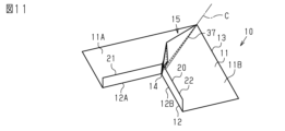
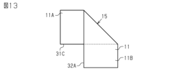
- a roof drainage member 10 according to a third embodiment will be described with reference to Figures 12 to 15.
- components common to the first embodiment are given the same reference numerals as those in the first embodiment, and descriptions of overlapping components will be omitted.
- the roof drainage member 10 comprises a base portion 11, a first rising portion 21, and a second rising portion 22.
- the roof drainage member 10 is formed by bending one component member 30. In the unfolded state before bending, the component member 30 has a lower end 31 that extends in a straight line and an upper end 32 that is parallel to the lower end 31 (see FIG. 12).
- the lower end 31 of the component member 30 has a third lower end 31C.
- the upper end 32 of the component member 30 has a first upper end 32A.
- the base portion 11 has a bent portion 15 that is bent so that the third lower end 31C of the component member 30 and the first upper end 32A of the component member 30 intersect with each other.
- the folded portion 15 has a valley fold 41 that diagonally intersects the lower end 31 and the upper end 32.
- the folded portion 15 extends from the lower end 31 toward the upper end 32.
- the valley fold 41 intersects with the lower end 31 at a predetermined angle (see FIG. 12 ).
- the predetermined angle is an angle in the range of 30 degrees to 60 degrees.
- the component 30 is folded at the valley fold 41.
- the base portion 11 has a first plate portion 11A that extends diagonally downward from the base center line C in the attached state, and a second plate portion 11B that extends diagonally downward from the base center line C in the attached state.
- the second plate portion 11B is configured symmetrically to the first plate portion 11A with respect to the base center line C.
- the first raised portion 21 is formed by bending a portion of the component 30 that includes the third lower end 31C.
- the second raised portion 22 is formed by bending a portion of the component 30 that includes a first upper end 32A.
- FIG. 12 A method of forming the roof flashing member 10 will be described with reference to Figures 12 to 15. As shown in FIG. 12, in the first step, a sixth line L6 for a valley fold 41 is drawn in the middle of the rectangular component member 30 in the longitudinal direction.
- the component 30 in a second step, is valley-folded along the sixth line L6, so that the third lower end 31C and the first upper end 32A of the component 30 intersect with each other.
- a third incision 43 is made in the component 30 near the third lower end 31C and a fourth incision 44 is made in the component 30 near the first upper end 32A.
- the first raised portion 21 is formed by bending the portion of the component 30 that includes the third lower end 31C.
- the second raised portion 22 is formed by bending the portion of the component 30 that includes the first upper end 32A.
- the bent portion 15 is a portion bent so that a third lower end 31C, which is a part of the lower end 31, and a first upper end 32A, which is a part of the upper end 32, intersect.
- the first raised portion 21 is formed by bending a portion of the component member 30 that includes the third lower end 31C.
- the second raised portion 22 is formed by bending a portion of the component member 30 that includes the first upper end 32A.
- a roof dripping member 10 according to a third embodiment will be described with reference to Figures 16 to 18.
- components common to the first embodiment are given the same reference numerals as those in the first embodiment, and descriptions of overlapping components will be omitted.
- the roof drainage member 10 includes a base portion 11, a first rising portion 21, and a second rising portion 22.
- the roof drainage member 10 is composed of a first component member 51 and a second component member 52.
- the first component 51 has a first rising portion 21.
- the first rising portion 21 is formed by bending the first component 51. Specifically, the first rising portion 21 is formed by bending a portion including a first lower end 51B at a lower end 51A of the first component 51.
- the first rising portion 21 is provided with an extension portion 53.
- the extension portion 53 is formed as a portion that overlaps the second rising portion 22.
- the extension portion 53 extends from a first side end 21A of the first rising portion 21.
- the first side end 21A is an end of the first rising portion 21 that is closer to the second rising portion 22 when the first component 51 and the second component 52 are joined together.
- the first component 51 further has a first region R1 that overlaps the second component 52.
- the second component member 52 has a second rising portion 22.
- the second rising portion 22 is formed by bending the second component member 52. Specifically, the second rising portion 22 is formed by bending a portion of the lower end 52A of the second component member 52 including the second lower end 52B.
- An extension portion 53 extending from the first rising portion 21 is overlapped on the second rising portion 22 (see FIG. 18 ).
- the second rising portion 22 is connected to the first rising portion 21 by the extension portion 53.
- the second component member 52 further has a second region R2 overlapping the first component member 51.
- the base portion 11 is composed of a first component member 51 and a second component member 52. Specifically, the base portion 11 has a portion where the first region R1 of the first component member 51 and the second region R2 of the second component member 52 overlap.
- the base portion 11 has a first plate portion 11A that extends diagonally downward from the base center line C in the attached state, and a second plate portion 11B that extends diagonally downward from the base center line C in the attached state.
- the second plate portion 11B is configured symmetrically to the first plate portion 11A with respect to the base center line C.
- a method of forming the roof flashing member 10 will be described with reference to Figures 16 to 18.
- a long rectangular plate-like member is divided into two to produce a first component member 51 and a second component member 52.
- a fifth cut 55 is made in a portion corresponding to the extension portion 53, and further, a portion corresponding to the first lower end 51B is folded to produce the first rising portion 21 and the extension portion 53.
- the portions other than the portions corresponding to the first rising portion 21 and the extension portion 53 are folded back.
- the second raised portion 22 is created by bending the portion of the rectangular second component member 52 that corresponds to the second lower end 52B. Then, the portion of the lower end 52A other than the portion that corresponds to the second raised portion 22 is bent backwards.
- the first region R1 of the first component 51 is overlapped on the second region R2 of the second component 52 so that the first rising portion 21 and the second rising portion 22 intersect. Then, the first region R1 of the first component 51 and the second region R2 of the second component 52 are joined by a joining means. Furthermore, the extension portion 53 extending from the first rising portion 21 is joined to the second rising portion 22 by a joining means. Examples of joining means include bonding with an adhesive, welding, brazing, joining with rivets, etc.
- the first rising portion 21 is formed by bending the first component member 51.
- the second rising portion 22 is formed by bending the second component member 52.
- the base portion 11 is formed by the first component member 51 and the second component member 52.
- the roof flashing member 10 is formed by the first component member 51 and the second component member 52.
- Such a roof flashing member 10 can improve dimensional accuracy because it has fewer bending structures.
- the roof flashing member 10 is formed by joining the first component member 51, which has a simple rectangular shape, to the second component member 52, which also has a simple rectangular shape, less waste material is generated.
- the first raised portion 21 is connected to the second raised portion 22 by an extension portion 53 extending from the first raised portion 21. This makes it possible to prevent water from leaking from the gap between the first raised portion 21 and the second raised portion 22.
- the above-described embodiments are examples of possible forms of the roof flashing member 10 and the roof 1, and are not intended to limit the forms.
- the roof flashing member 10 and the roof 1 may take forms different from those exemplified in the above-described embodiments. Examples of such forms include those in which a part of the configuration of each embodiment is replaced, changed, or omitted, or those in which a new configuration is added to the embodiment. Modified examples of the embodiments are shown below.
- the roof flashing member 10 may be manufactured in a factory. Also, the roof flashing member 10 may be created by workers at a construction site of a building. In each embodiment, the order of folding is not limited. For example, in the first embodiment, the folding for forming the first rising portion 21 and the second rising portion 22 may be performed before the mountain fold and the valley fold.
- the roof flashing member is provided on a roof underlayment of a sloping roof, and includes a base portion arranged to follow the roof underlayment, and a rising portion provided at a base lower end of the base portion in an attached state in which the roof flashing member is attached to the roof underlayment.
- the base lower end has a first base lower end extending diagonally downward from a base lower end apex portion in the attached state, and a second base lower end extending diagonally downward from the base lower end apex portion in a direction different from the direction in which the first base lower end extends.
- the rising portion has a first rising portion configured as a portion rising to follow the first base lower end by bending a component member constituting the roof flashing member, and a second rising portion configured as a portion rising to follow the second base lower end by bending the component member.
- the component has, in an unfolded state before folding, a lower end that extends in a straight line and an upper end that is parallel to the lower end.
- the base portion has a folded portion that is folded so that a first lower end that is a part of the lower end and a second lower end that is a part of the lower end other than the first lower end intersect.
- the first raised portion is formed by folding a portion of the component including the first lower end.
- the second raised portion is formed by folding a portion of the component including the second lower end.
- the folding portion has a mountain fold portion perpendicular to the lower end and a valley fold portion.
- the valley fold portion extends from an intersection of the upper end and the mountain fold portion so as to diagonally intersect with the mountain fold portion in the unfolded state.
- the folded portion has a mountain fold perpendicular to the lower end, a first valley fold, and a second valley fold.
- the first valley fold extends from an intersection of the upper end and the mountain fold so as to intersect the mountain fold obliquely in a first direction in the unfolded state.
- the second valley fold extends from an intersection of the upper end and the mountain fold so as to intersect the mountain fold obliquely in a second direction different from the first direction in the unfolded state.
- the component has a lower end that extends in a straight line and an upper end that is parallel to the lower end in an unfolded state before folding.
- the base portion has a bent portion that is bent so that a third lower end that is a part of the lower end and a first upper end that is a part of the upper end intersect.
- the first raised portion is formed by folding a portion of the component that includes the third lower end.
- the second raised portion is formed by folding a portion of the component that includes the first upper end.
- the first rising portion is formed by bending a first component member
- the second rising portion is formed by bending a second component member
- the base portion is formed by the first component member and the second component member.
- a sloping roof comprising the roof flashing member according to any one of appendices 1 to 6.
- the roof flashing member is disposed above a through hole in a roof underlayment.
Landscapes
- Engineering & Computer Science (AREA)
- Architecture (AREA)
- Civil Engineering (AREA)
- Structural Engineering (AREA)
- Roof Covering Using Slabs Or Stiff Sheets (AREA)
- Building Environments (AREA)
Priority Applications (4)
| Application Number | Priority Date | Filing Date | Title |
|---|---|---|---|
| GB2515056.6A GB2642608A (en) | 2023-03-27 | 2023-03-27 | Roof-draining member and roof provided with roof-draining member |
| AU2023438983A AU2023438983A1 (en) | 2023-03-27 | 2023-03-27 | Roof-draining member and roof provided with roof-draining member |
| JP2025509306A JPWO2024201682A1 (https=) | 2023-03-27 | 2023-03-27 | |
| PCT/JP2023/012343 WO2024201682A1 (ja) | 2023-03-27 | 2023-03-27 | 屋根水切り部材および屋根水切り部材を備える屋根 |
Applications Claiming Priority (1)
| Application Number | Priority Date | Filing Date | Title |
|---|---|---|---|
| PCT/JP2023/012343 WO2024201682A1 (ja) | 2023-03-27 | 2023-03-27 | 屋根水切り部材および屋根水切り部材を備える屋根 |
Publications (1)
| Publication Number | Publication Date |
|---|---|
| WO2024201682A1 true WO2024201682A1 (ja) | 2024-10-03 |
Family
ID=92903530
Family Applications (1)
| Application Number | Title | Priority Date | Filing Date |
|---|---|---|---|
| PCT/JP2023/012343 Ceased WO2024201682A1 (ja) | 2023-03-27 | 2023-03-27 | 屋根水切り部材および屋根水切り部材を備える屋根 |
Country Status (4)
| Country | Link |
|---|---|
| JP (1) | JPWO2024201682A1 (https=) |
| AU (1) | AU2023438983A1 (https=) |
| GB (1) | GB2642608A (https=) |
| WO (1) | WO2024201682A1 (https=) |
Citations (4)
| Publication number | Priority date | Publication date | Assignee | Title |
|---|---|---|---|---|
| JPH01150726U (https=) * | 1988-03-29 | 1989-10-18 | ||
| JPH0218050U (https=) * | 1988-07-15 | 1990-02-06 | ||
| US5077943A (en) * | 1990-07-19 | 1992-01-07 | Mcgady Donald L | Corner flashing |
| US5675940A (en) * | 1996-10-15 | 1997-10-14 | Bahar; Reuben | Skylight leakage barrier |
-
2023
- 2023-03-27 JP JP2025509306A patent/JPWO2024201682A1/ja active Pending
- 2023-03-27 AU AU2023438983A patent/AU2023438983A1/en active Pending
- 2023-03-27 WO PCT/JP2023/012343 patent/WO2024201682A1/ja not_active Ceased
- 2023-03-27 GB GB2515056.6A patent/GB2642608A/en active Pending
Patent Citations (4)
| Publication number | Priority date | Publication date | Assignee | Title |
|---|---|---|---|---|
| JPH01150726U (https=) * | 1988-03-29 | 1989-10-18 | ||
| JPH0218050U (https=) * | 1988-07-15 | 1990-02-06 | ||
| US5077943A (en) * | 1990-07-19 | 1992-01-07 | Mcgady Donald L | Corner flashing |
| US5675940A (en) * | 1996-10-15 | 1997-10-14 | Bahar; Reuben | Skylight leakage barrier |
Also Published As
| Publication number | Publication date |
|---|---|
| GB2642608A (en) | 2026-01-14 |
| AU2023438983A1 (en) | 2025-09-11 |
| JPWO2024201682A1 (https=) | 2024-10-03 |
Similar Documents
| Publication | Publication Date | Title |
|---|---|---|
| JP5671643B2 (ja) | 屋根パネル及び建物の屋根構造 | |
| JP5588556B1 (ja) | コーナー水切り材、屋根パネル及び建物の屋根構造 | |
| WO2024201682A1 (ja) | 屋根水切り部材および屋根水切り部材を備える屋根 | |
| EP2034099A2 (en) | Module for a modular roof, method for assembling a modular roof and modular roof | |
| JP7222401B2 (ja) | 屋根の製造方法及び屋根構造並びにそれらに用いる屋根ユニット | |
| JP7413139B2 (ja) | 屋根構造及びカバー部材 | |
| JP5410255B2 (ja) | 建物 | |
| JP2002332720A (ja) | 箱型はぜ葺き屋根、太陽電池モジュール板を組み込んだ箱型はぜ葺き屋根、太陽電池モジュール板の取りつけ、取り外し方法および屋根の施工方法 | |
| JP3831493B2 (ja) | 建物の屋根構造 | |
| JP2020200615A (ja) | 平板スレート屋根の補修構造、補修方法、並びに補修用谷板 | |
| JP5651229B1 (ja) | 屋根パネルの接続構造及び建物の屋根構造 | |
| JP2013144912A (ja) | 屋根構造 | |
| JP3843018B2 (ja) | 増築建物とその施工方法 | |
| JP2011117137A (ja) | 屋根構造 | |
| JP2022142047A (ja) | 雨押え構造体 | |
| JP3865625B2 (ja) | 建物の屋根構造 | |
| KR20060092441A (ko) | 패널방식의 지붕 골조 시스템 | |
| JP2025089626A (ja) | 庇構造 | |
| JP3097027B2 (ja) | 瓦棒屋根の改築方法および改築屋根 | |
| JP2003227177A (ja) | ユニット建物 | |
| JPH05171729A (ja) | 屋根構造 | |
| JPH0643301Y2 (ja) | 柱上パネル受具 | |
| JPH11229727A (ja) | 開口部付き屋根 | |
| JP2010070999A (ja) | 屋根の構造 | |
| JPH0953307A (ja) | 腰折れ屋根 |
Legal Events
| Date | Code | Title | Description |
|---|---|---|---|
| 121 | Ep: the epo has been informed by wipo that ep was designated in this application |
Ref document number: 23930322 Country of ref document: EP Kind code of ref document: A1 |
|
| WWE | Wipo information: entry into national phase |
Ref document number: AU2023438983 Country of ref document: AU |
|
| ENP | Entry into the national phase |
Ref document number: 2025509306 Country of ref document: JP Kind code of ref document: A |
|
| WWE | Wipo information: entry into national phase |
Ref document number: 2025509306 Country of ref document: JP |
|
| ENP | Entry into the national phase |
Ref document number: 2023438983 Country of ref document: AU Date of ref document: 20230327 Kind code of ref document: A Ref document number: 202515056 Country of ref document: GB Kind code of ref document: A Free format text: PCT FILING DATE = 20230327 |
|
| WWE | Wipo information: entry into national phase |
Ref document number: 2515056.6 Country of ref document: GB |
|
| NENP | Non-entry into the national phase |
Ref country code: DE |
|
| WWP | Wipo information: published in national office |
Ref document number: 2515056.6 Country of ref document: GB |
|
| 122 | Ep: pct application non-entry in european phase |
Ref document number: 23930322 Country of ref document: EP Kind code of ref document: A1 |