WO2024201591A1 - レーダの取付構造 - Google Patents
レーダの取付構造 Download PDFInfo
- Publication number
- WO2024201591A1 WO2024201591A1 PCT/JP2023/011914 JP2023011914W WO2024201591A1 WO 2024201591 A1 WO2024201591 A1 WO 2024201591A1 JP 2023011914 W JP2023011914 W JP 2023011914W WO 2024201591 A1 WO2024201591 A1 WO 2024201591A1
- Authority
- WO
- WIPO (PCT)
- Prior art keywords
- vertical wall
- radar
- top plate
- vehicle
- bracket
- Prior art date
- Legal status (The legal status is an assumption and is not a legal conclusion. Google has not performed a legal analysis and makes no representation as to the accuracy of the status listed.)
- Ceased
Links
Images


Classifications
-
- G—PHYSICS
- G01—MEASURING; TESTING
- G01S—RADIO DIRECTION-FINDING; RADIO NAVIGATION; DETERMINING DISTANCE OR VELOCITY BY USE OF RADIO WAVES; LOCATING OR PRESENCE-DETECTING BY USE OF THE REFLECTION OR RERADIATION OF RADIO WAVES; ANALOGOUS ARRANGEMENTS USING OTHER WAVES
- G01S13/00—Systems using the reflection or reradiation of radio waves, e.g. radar systems; Analogous systems using reflection or reradiation of waves whose nature or wavelength is irrelevant or unspecified
- G01S13/88—Radar or analogous systems specially adapted for specific applications
- G01S13/93—Radar or analogous systems specially adapted for specific applications for anti-collision purposes
- G01S13/931—Radar or analogous systems specially adapted for specific applications for anti-collision purposes of land vehicles
-
- G—PHYSICS
- G01—MEASURING; TESTING
- G01S—RADIO DIRECTION-FINDING; RADIO NAVIGATION; DETERMINING DISTANCE OR VELOCITY BY USE OF RADIO WAVES; LOCATING OR PRESENCE-DETECTING BY USE OF THE REFLECTION OR RERADIATION OF RADIO WAVES; ANALOGOUS ARRANGEMENTS USING OTHER WAVES
- G01S7/00—Details of systems according to groups G01S13/00, G01S15/00, G01S17/00
- G01S7/02—Details of systems according to groups G01S13/00, G01S15/00, G01S17/00 of systems according to group G01S13/00
- G01S7/03—Details of HF subsystems specially adapted therefor, e.g. common to transmitter and receiver
Definitions
- This case concerns the mounting structure of a radar that is installed at the front or rear end of a vehicle and emits radar waves.
- radar millimeter wave radar, laser radar, etc.
- the radar is fixed to the vehicle body via a mounting member (bracket) (see, for example, Patent Document 1).
- the radar irradiates radar waves (radio waves, laser beams, etc.) toward the front and rear of the vehicle, and detects, for example, the presence or absence of an object within this irradiation range and the distance to the object. Detection by the radar needs to be performed with high accuracy. For this reason, the radar can be firmly fixed to the vehicle body to prevent the radar from vibrating due to the shaking of the vehicle while it is traveling.
- Patent Document 2 discloses a configuration in which the bracket that secures the radar is provided with deformation sections (first deformation section, second deformation section, etc.) formed, for example, by notches. With this configuration, it is said that when a load is applied, the deformation sections easily deform, causing the radar located in front of the vehicle to move backward, thereby reducing the impact on the object being hit.
- Patent Document 2 when the portion that becomes the starting point of deformation when a load is applied is configured as a notch, there is a problem in that stress concentration is likely to occur in the notch portion.
- the pedestrian When a vehicle comes into contact with a pedestrian, the pedestrian may collide with the radar head-on or may collide with the radar in a position that is not directly facing the radar. Therefore, in either case, a configuration that can reduce the load (shock) on the pedestrian is desirable.
- the radar mounting structure in this case was devised in consideration of these issues, and one of its objectives is to improve pedestrian protection performance in the event of a vehicle collision. However, this objective is not the only objective. Another objective of this case is to achieve effects that cannot be obtained with conventional technology, which are derived from the configurations shown in the "Mode for Carrying Out the Invention" described below.
- the disclosed vehicle body structure can be realized as the embodiments (application examples) disclosed below, which solve at least part of the above problems.
- Each embodiment from embodiment 2 onwards is an embodiment that can be selected additionally as appropriate, and each is an embodiment that can be omitted. None of the embodiments from embodiment 2 onwards discloses an embodiment or configuration that is essential to the present case.
- the disclosed radar mounting structure includes a radar that emits radar waves, and a bracket that is provided at the front or rear end of a vehicle, connects and fixes two vehicle body members at different heights in the vertical direction, and fixes the radar.
- the bracket has a first portion that is hat-shaped when viewed from the side of the vehicle, including a first top plate that is spaced in the front-rear direction from a first fixing surface for the vehicle body member and to which the radar is fixed, and an upper vertical wall and a lower vertical wall that extend from the upper edge and lower edge of the first top plate toward the first fixing surface.
- the bracket has a second portion that is hat-shaped when viewed from above the vehicle, including a second top plate that is spaced in the front-rear direction from a second fixing surface for the vehicle body member and is provided at least one of the upper edge of the upper vertical wall and the lower edge of the lower vertical wall, and a left vertical wall and a right vertical wall that extend from the left edge and right edge of the second top plate toward the second fixing surface.
- bracket extends from the first top plate to the left vertical wall and the right vertical wall and has a convex or concave bead.
- bracket extends from the first top plate to the left vertical wall and the right vertical wall and has a convex or concave bead.
- bracket extends from the first top plate to the left vertical wall and the right vertical wall and has a convex or concave bead.
- Aspect 3 it is preferable that the upper vertical wall and the lower vertical wall extend obliquely with respect to the first top plate, and the left vertical wall and the right vertical wall extend obliquely with respect to the second top plate.
- the second portion has the second top plate formed continuously from a lower edge of the lower vertical wall and fixed to a bumper beam as the lower vehicle body member.
- Aspect 5 In any of Aspects 1 to 3 above, it is preferable that the second top plate is formed continuously from an upper edge of the upper vertical wall and a lower edge of the lower vertical wall.
- the bracket has a third portion that protrudes in a direction away from the first fixing surface in the front-rear direction beyond the radar fixed to the first top plate.
- Aspect 7 In the above aspect 6, it is preferable that the third portion is a surface portion extending in the up-down direction and the front-rear direction along each of the left edge and the right edge of the first tabletop.
- Aspect 8 In any of Aspects 1 to 7 above, it is preferable that the first portion and the second portion of the bracket are integrally formed.
- the disclosed radar mounting structure allows the bracket to deform and appropriately release the radar regardless of the pedestrian's collision position relative to the radar, thereby improving pedestrian protection performance in the event of a vehicle collision.
- FIG. 2 is a perspective view illustrating a mounting structure of the radar according to the embodiment.
- 2 is a perspective view of the radar and the bracket included in the mounting structure of FIG. 1, viewed from the lower left.
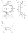
- FIG. 3A is a front view of the bracket of FIG. 2
- FIG. 3B is a right side view (viewed in the direction of the arrow B in FIG. 3A)
- FIG. 3C is a bottom view (viewed in the direction of the arrow C in FIG. 3A).
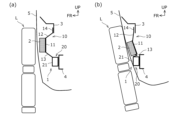
- 2A and 2B are schematic left side views for explaining the action when a pedestrian directly faces the radar and collides with a vehicle having the mounting structure of FIG. 1 , where FIG. 2A shows the state immediately before the collision, and FIG. 2B shows the state at the time of the collision.
- FIG. 2A and 2B are schematic top views for explaining the action when a pedestrian collides with a vehicle having the mounting structure of FIG. 1 without facing the radar directly, in which (a) shows the state immediately before the collision, and (b) shows the state at the time of the collision.
- the definition of directions is that the front-to-rear direction (vehicle length direction) is defined based on the forward and backward direction of the vehicle, and the left-to-right direction (vehicle width direction) is defined based on the front-to-rear direction.
- the up-to-down direction is defined based on the state in which the vehicle is stopped on a flat road surface.
- This mounting structure can be applied to either the front or rear of a vehicle.
- this mounting structure is a structure for fixing a radar that irradiates radar waves to the front of the vehicle to the front end of the vehicle using a bracket.
- this mounting structure is a structure for fixing a radar that irradiates radar waves to the rear of the vehicle to the rear end of the vehicle using a bracket.
- Fig. 1 is a diagram for explaining a mounting structure applied to the front side of a vehicle, and is a perspective view of the front end of the vehicle as viewed from a slightly leftward direction.
- the mounting structure of this embodiment includes a radar 2 that irradiates radar waves and a bracket 1 to which the radar 2 is fixed.
- One mounting structure is provided at approximately the center in the vehicle width direction.
- the radar 2 is a detection device such as a millimeter wave radar or laser radar.
- the radar 2 for example, emits radar waves (radio waves, laser beams, etc.) toward the front of the vehicle, and detects the presence or absence of objects within this irradiation range and the distance to the objects.
- the irradiation range of the radar 2 expands radially the further away from the radar 2 (the further forward the vehicle).
- the radar 2 in this embodiment is composed of a rectangular parallelepiped radar body 2A and a frame body 2B that is fixed to the bracket 1 with the radar body 2A attached.
- the bracket 1 is provided at the front end of the vehicle.
- the bracket 1 connects two vehicle body members 3, 4 arranged at different heights in the vertical direction and is fixed to the vehicle body members 3, 4.
- the upper body member 3 is a bumper bracket
- the lower body member 4 is a bumper beam.
- the bumper bracket 3 is a member to which the bumper fascia 5 is attached and fixed to the vehicle body.
- the bumper beam 4 is a structural member that extends in the vehicle width direction and connects between a pair of left and right side members (not shown) that extend in the front-rear direction.
- the bumper beam 4 has a higher strength than the bumper bracket 3.
- These body members 3, 4 are disposed spaced apart from each other in the up-down direction.
- these body members 3, 4 may be disposed such that the positions of their respective front faces are slightly spaced apart in the front-rear direction.
- the bracket 1 has its upper portion fixed to the upper vehicle body member 3 and its lower portion fixed to the lower vehicle body member 4.
- first fixing surface 1A the former fixing point
- second fixing surface 1B the latter fixing point
- the bracket 1 is mechanically fastened and fixed at these fixing surfaces 1A and 1B, for example, by bolts or screws. This suppresses shaking of the bracket 1 (and thus the radar 2) due to vehicle body vibrations while traveling.
- FIG. 2 is a perspective view of the bracket 1 with the radar 2 fixed thereto, viewed from below and to the left.
- FIGS. 3(a)-(c) are a front view, a left side view, and a bottom view of the bracket 1, respectively. Note that in FIG. 3(b), parts of the vehicle body members 3 and 4 are indicated by two-dot chain lines.
- the bracket 1 has a first portion 10 that is hat-shaped when viewed from the side of the vehicle, and a second portion 20 that is hat-shaped when viewed from above (or below) the vehicle.
- the first portion 10 and the second portion 20 are provided integrally.
- the bracket may also have the first portion 10 and the second portion 20 provided separately and integrated (joined, welded, etc.).
- the first portion 10 is a hat-shaped portion that opens rearward when viewed from the side of the vehicle, and has a first top plate 11, an upper vertical wall 12, a lower vertical wall 13, and an upper flange 14.
- the first top plate 11 is the surface portion to which the radar 2 is fixed, and extends in the vertical direction and the vehicle width direction. As shown in FIG. 3(b), the first top plate 11 forms the top surface portion of the hat shape, and is positioned at a distance from the first fixing surface 1A in the fore-and-aft direction (forward in this embodiment).
- the first top plate 11 of this embodiment has a substantially rectangular fixing surface 11a and extensions 11b extending upward and downward from the centers of the upper and lower edges of the fixing surface 11a.
- the fixing surface 11a is formed in a substantially rectangular shape that is equal to or slightly larger than the outer shape of the frame body 2B of the radar 2.
- the fixing surface 11a may be provided with holes for fixing the radar 2, openings through which the wiring of the radar 2 is inserted, etc.
- the extensions 11b are not essential and may be omitted.
- the upper vertical wall 12 is a surface portion extending from the upper edge of the first top plate 11 toward the first fixed surface 1A, and extends at least in the vehicle width direction.
- the upper vertical wall 12 is continuously formed from the upper edge of the upper extension portion 11b of the first top plate 11 toward the rear and slightly upward.
- the lower vertical wall 13 is a surface portion extending from the lower edge of the first top plate 11 toward the first fixed surface 1A, and extends at least in the vehicle width direction.
- the lower vertical wall 13 is continuously formed from the lower edge of the lower extension portion 11b of the first top plate 11 toward the rear and slightly downward.
- both the upper vertical wall 12 and the lower vertical wall 13 extend obliquely with respect to the first top plate 11 so that the angle with the first top plate 11 is greater than 90 degrees.
- the upper flange 14 is a surface portion formed continuously upward from the upper edge of the upper vertical wall 12, and constitutes the first fixed surface 1A described above.
- the upper flange 14 is the part that is fixed to the upper vehicle body member 3.
- the first part 10 does not have a lower flange that corresponds to the upper flange 14, and the second top plate 21 (described below) of the second part 20 is provided at the position of this lower flange.
- the first portion 10 of this embodiment has a pair of upper ribs 15 that run along the left and right edges of the upper vertical wall 12 and protrude upward and forward. Furthermore, the first portion 10 has a pair of lower ribs 16 that run along the left and right edges and protrude at least forward from the lower extension 11b to the lower vertical wall 13.
- the upper ribs 15 and lower ribs 16 contribute to improving the rigidity of the bracket 1. Note that these upper ribs 15 and lower ribs 16 are not essential and can be omitted.
- the second portion 20 is a hat-shaped portion that opens rearward when viewed from the top-bottom direction of the vehicle, and has a second top plate 21, a left vertical wall 22, a right vertical wall 23, a left flange 24, and a right flange 25.
- the second top plate 21 is a surface portion provided on the lower edge of the lower vertical wall 13 of the first portion 10, and is provided continuously downward from this lower edge and extends in the up-down and vehicle width directions.
- the second top plate 21 forms the top surface portion of the hat shape, and is disposed spaced apart from the second fixing surface 1B in the fore-and-aft direction (forward in this embodiment).
- the first portion 10 forms an upper hat structure in the vertical direction (up-down direction)
- the second portion 20 forms a lower hat structure in the horizontal direction (vehicle width direction).
- the second top plate 21 in this embodiment is generally rectangular in shape with a left-right dimension that is longer than the top-down dimension.
- the left-right dimension of the second top plate 21 is at least equal to or greater than the left-right dimension of the lower edge of the lower vertical wall 13.
- the top-down dimension of the second top plate 21 is also generally equal to the top-down dimension of the upper flange 14, and its front-to-rear position is generally equal to the front-to-rear position of the upper flange 14.
- the second top plate 21 can also be said to be a part that replaces the lower flange of the first part 10.
- the left vertical wall 22 is a surface portion extending from the left edge of the second top plate 21 toward the second fixed surface 1B, and extends at least in the front-rear direction.
- the left vertical wall 22 is continuously formed from the entire left edge of the second top plate 21 toward the rear and left (outside the vehicle).
- the right vertical wall 23 is a surface portion extending from the right end of the second top plate 21 toward the second fixed surface 1B, and extends at least in the front-rear direction.
- the right vertical wall 23 is continuously formed from the entire right edge of the second top plate 21 toward the rear and right (outside the vehicle). In other words, both the left vertical wall 22 and the right vertical wall 23 extend obliquely with respect to the second top plate 21 so that the angle with the second top plate 21 is greater than 90 degrees.
- the left flange 24 is a surface portion that is continuously formed from the entire left edge of the left vertical wall 22 to the left (outside of the vehicle), and constitutes the above-mentioned second fixing surface 1B.
- the right flange 25 is a surface portion that is continuously formed from the entire right edge of the right vertical wall 23 to the right (outside of the vehicle), and constitutes the above-mentioned second fixing surface 1B.
- both the left flange 24 and the right flange 25 are parts that are fixed to the lower body member 4.
- the bracket 1 of this embodiment has a bead 40 that extends from the first top plate 11 to the left vertical wall 22 and the right vertical wall 23.
- the bead 40 is a portion whose plate surface is concave or convex.
- the bead 40 extends from the lower extension 11b of the first top plate 11 to the lower vertical wall 13 and the second top plate 21, and branches to the left and right at the second top plate 21, with the left end extending to the left vertical wall 22 and the right end extending to the right vertical wall 23.
- the bead 40 has an inverted T-shape when the bracket 1 is viewed from the front.
- the beads 40 are provided across the corners formed by the first top plate 11 and the lower vertical wall 13, the corners formed by the lower vertical wall 13 and the second top plate 21, the corners formed by the second top plate 21 and the left vertical wall 22, and the corners formed by the second top plate 21 and the right vertical wall 23. This improves the rigidity of the surface portion (corner) on which the beads 40 are provided without increasing the plate thickness of the bracket 1.
- the bracket 1 of this embodiment has a third portion 30 that protrudes forward (in the direction away from the first fixed surface 1A in the front-rear direction) from the radar 2 fixed to the first top plate 11.
- the front end portion of the third portion 30 is located forward of the forefront position of the radar 2. This makes it easier for the load to be input to the third portion 30 before the radar 2 in the event of a vehicle collision, and damage to the radar 2 can be suppressed.
- the third portion 30 in this embodiment is a surface portion that extends in the up-down and front-rear directions along the left and right edges of the first top plate 11, as shown in FIG. 2 and FIG. 3(a)-(c). That is, a pair of third portions 30 are provided on the left and right sides. More specifically, the left third portion 30 extends forward from substantially the entire left edge of the fixing surface 11a of the first top plate 11, and is provided as a substantially rectangular planar portion in side view. Similarly, the right third portion 30 extends forward from substantially the entire right edge of the fixing surface 11a of the first top plate 11, and is provided as a substantially rectangular planar portion in side view. As shown in FIG. 3(c), the bracket 1 forms a U-shape that is open forward with the first top plate 11 and the left and right third portions 30. The radar 2 is disposed inside this U-shape.
- the bracket 1 is provided at the front end of the vehicle, connects two vehicle body members 3, 4 arranged at different heights in the vertical direction, and is fixed to these vehicle body members 3, 4.
- the bracket 1 has a first portion 10 that is hat-shaped when viewed from the side of the vehicle, and a second portion 20 that is hat-shaped when viewed from above (or below) the vehicle.
- the first portion 10 includes a first top plate 11, which is spaced forward from a first fixing surface 1A for the vehicle body member 3 and to which the radar 2 is fixed, and an upper vertical wall 12 and a lower vertical wall 13 extending rearward (toward the first fixing surface 1A) from the upper and lower edges of the first top plate 11, respectively.
- the second portion 20 includes a second top plate 21, which is spaced forward from a second fixing surface 1B for the vehicle body member 4 and is provided on the lower edge of the lower vertical wall 13, and a left vertical wall 22 and a right vertical wall 23 extending rearward (toward the second fixing surface 1B) from the left and right edges of the second top plate 21, respectively.
- the above-mentioned bracket 1 has a two-tiered hat structure consisting of a vertical upper hat structure (first portion 10) and a horizontal lower hat structure (second portion 20).
- the bracket 1 can deform to appropriately allow the radar 2 to escape regardless of the position at which the pedestrian collides with the radar 2, thereby improving pedestrian protection performance in the event of a vehicle collision.
- the illumination range of the radar 2 does not include any parts or parts that make up the vehicle (for example, uneven parts of the bumper fascia 5, bolts, etc.) to avoid false detection.
- the area of the bumper fascia 5 that overlaps with the illumination range of the radar 2 needs to be a substantially flat surface without uneven parts.
- the portion to which the radar 2 is fixed (first top plate 11) can be moved forward and away from the first fixing surface 1A to the vehicle body member 3.
- the radar 2 can be positioned closer to the bumper fascia 5. This makes it possible to reduce the area of the bumper fascia 5 that overlaps with the irradiation range of the radar 2, thereby narrowing the constraints on the bumper fascia 5 (the area that must be a substantially flat surface without uneven parts). This increases the freedom of design of the bumper fascia 5.
- the bracket 1 extends from the first top plate 11 to the left vertical wall 22 and the right vertical wall 23, and has a convex or concave bead 40. Under normal circumstances other than when a vehicle collision occurs, the bracket 1 needs to protect the radar 2 from vehicle vibrations in order to prevent false detections by the radar 2, and is therefore required to have a certain degree of rigidity. On the other hand, in the event of a collision with a pedestrian, the bracket 1 needs to deform to absorb the load (shock).
- the bead 40 is provided across the connecting portion between the first portion 10 and the second portion 20, so the rigidity of the portion where the bead 40 is provided can be increased without excessively increasing the strength of the entire bracket 1. In this way, the rigidity of the bracket 1 can be increased and vibrations suppressed without affecting pedestrian protection, and false detection by the radar 2 can be suppressed.
- the upper vertical wall 12 and the lower vertical wall 13 of the first portion 10 extend obliquely relative to the first top plate 11, and the left vertical wall 22 and the right vertical wall 23 of the second portion 20 extend obliquely relative to the second top plate 21.
- the vertical walls 12, 13, 22, and 23 are inclined rather than perpendicular to the top plates 11 and 21, when a load (impact) is applied, the vertical walls 12, 13, 22, and 23 are easily deformed without being stiffened. This further improves pedestrian protection performance.
- the second top plate 21 of the second part 20 of the bracket 1 is formed continuously from the lower edge of the lower vertical wall 13 of the first part 10 and is fixed to the bumper beam as the lower vehicle body member 4.
- the bumper beam 4 has high strength and is not easily deformed during a collision, so the second part 20 is fixed to the bumper beam 4, making it easy to absorb the reaction force. Therefore, when a collision occurs in a position where the pedestrian and the radar 2 are not directly facing each other, the bracket 1 is more likely to deform, so that the pedestrian protection performance can be further improved.
- the vibration of the radar 2 can be suppressed.
- the bracket 1 can be made lighter than a configuration in which the second part 20 is provided both above and below the first part 10.
- the bracket 1 described above has a third portion 30 that protrudes forward from the radar 2 fixed to the first top plate 11.
- the load is input to the third portion 30 before the radar 2, making it easier to suppress damage to the radar 2.
- the load can be absorbed by deformation of only the third portion 30, which can prevent damage to the radar 2. In this case, replacement costs in the event of a minor collision can be suppressed.
- the third portion 30 is provided as a surface portion extending in the up-down and front-rear directions along the left and right edges of the first top plate 11. In this way, by providing the third portion 30 as a surface portion on each of the left and right edges of the first top plate 11 so as to sandwich the radar 2 from the left and right, the third portion 30 can receive the load before the radar 2 regardless of the angle of collision, and damage to the radar 2 in the event of a light collision can be further prevented.
- the first portion 10 and the second portion 20 are integrally formed, making it possible to simplify and produce the bracket 1 at low cost.
- bracket 1 is provided with the second portion 20 only at the lower end of the first portion 10, but the second portion 20 may be provided only at the upper end of the first portion 10, or may be provided at both the upper and lower ends of the first portion 10.
- the bracket may include a second top plate provided at the upper edge of the upper vertical wall 12 of the first portion 10 (continuously formed from the upper edge), and a left vertical wall and a right vertical wall extending from the left edge and the right edge of the second top plate, respectively, toward the second fixing surface side, and may have a second portion that is hat-shaped when viewed from above (or below) the vehicle.
- the bracket is more likely to deform when a collision occurs at a position where the pedestrian and the radar 2 do not face each other. This makes it possible to further improve pedestrian protection performance.
- the third portion 30 may be a surface portion that follows the entire outer edge of the first portion 10, or may be formed in the shape of a protrusion or pin. Alternatively, the third portion 30 may be omitted.
- each vertical wall 12, 13, 22, 23 may be provided perpendicular to each top plate 11, 21, and the front-to-back dimensions of the upper vertical wall 12 and the lower vertical wall 13 do not have to be equal.
- a bead 40 is provided, its shape does not have to be an inverted T-shape. The bead 40 is not essential and can be omitted.
- the mounting structure applied to the front side of the vehicle has been described in detail, but this mounting structure may be applied only to the rear side of the vehicle, or to both the front and rear sides of the vehicle.
- the "front end of the vehicle” in the above-mentioned embodiment should be read as the "rear end of the vehicle"
- "front of the vehicle” or “front of the vehicle” should be read as "rear of the vehicle” or "rear of the vehicle”.
- This technology can be used in the vehicle manufacturing industry where radar mounting structures are used.
Landscapes
- Engineering & Computer Science (AREA)
- Radar, Positioning & Navigation (AREA)
- Remote Sensing (AREA)
- Physics & Mathematics (AREA)
- Computer Networks & Wireless Communication (AREA)
- General Physics & Mathematics (AREA)
- Electromagnetism (AREA)
- Radar Systems Or Details Thereof (AREA)
Priority Applications (2)
| Application Number | Priority Date | Filing Date | Title |
|---|---|---|---|
| JP2025509230A JP7816634B2 (ja) | 2023-03-24 | 2023-03-24 | レーダの取付構造 |
| PCT/JP2023/011914 WO2024201591A1 (ja) | 2023-03-24 | 2023-03-24 | レーダの取付構造 |
Applications Claiming Priority (1)
| Application Number | Priority Date | Filing Date | Title |
|---|---|---|---|
| PCT/JP2023/011914 WO2024201591A1 (ja) | 2023-03-24 | 2023-03-24 | レーダの取付構造 |
Publications (1)
| Publication Number | Publication Date |
|---|---|
| WO2024201591A1 true WO2024201591A1 (ja) | 2024-10-03 |
Family
ID=92904051
Family Applications (1)
| Application Number | Title | Priority Date | Filing Date |
|---|---|---|---|
| PCT/JP2023/011914 Ceased WO2024201591A1 (ja) | 2023-03-24 | 2023-03-24 | レーダの取付構造 |
Country Status (2)
| Country | Link |
|---|---|
| JP (1) | JP7816634B2 (https=) |
| WO (1) | WO2024201591A1 (https=) |
Citations (5)
| Publication number | Priority date | Publication date | Assignee | Title |
|---|---|---|---|---|
| JP2007030535A (ja) * | 2005-07-22 | 2007-02-08 | Mazda Motor Corp | レーダーユニットの取付構造 |
| JP2019167015A (ja) * | 2018-03-23 | 2019-10-03 | 本田技研工業株式会社 | 車体前部構造 |
| DE102018216784A1 (de) * | 2018-09-28 | 2020-04-02 | Continental Automotive Gmbh | Sensoranordnung für ein Fahrzeug und Fahrzeug |
| CN211918607U (zh) * | 2020-04-16 | 2020-11-13 | 广州汽车集团股份有限公司 | 前碰预警雷达安装结构和汽车 |
| CN213594230U (zh) * | 2020-11-09 | 2021-07-02 | 一汽解放汽车有限公司 | 一种车用的雷达固定结构及商用车 |
-
2023
- 2023-03-24 JP JP2025509230A patent/JP7816634B2/ja active Active
- 2023-03-24 WO PCT/JP2023/011914 patent/WO2024201591A1/ja not_active Ceased
Patent Citations (5)
| Publication number | Priority date | Publication date | Assignee | Title |
|---|---|---|---|---|
| JP2007030535A (ja) * | 2005-07-22 | 2007-02-08 | Mazda Motor Corp | レーダーユニットの取付構造 |
| JP2019167015A (ja) * | 2018-03-23 | 2019-10-03 | 本田技研工業株式会社 | 車体前部構造 |
| DE102018216784A1 (de) * | 2018-09-28 | 2020-04-02 | Continental Automotive Gmbh | Sensoranordnung für ein Fahrzeug und Fahrzeug |
| CN211918607U (zh) * | 2020-04-16 | 2020-11-13 | 广州汽车集团股份有限公司 | 前碰预警雷达安装结构和汽车 |
| CN213594230U (zh) * | 2020-11-09 | 2021-07-02 | 一汽解放汽车有限公司 | 一种车用的雷达固定结构及商用车 |
Also Published As
| Publication number | Publication date |
|---|---|
| JPWO2024201591A1 (https=) | 2024-10-03 |
| JP7816634B2 (ja) | 2026-02-18 |
Similar Documents
| Publication | Publication Date | Title |
|---|---|---|
| WO2014069113A1 (ja) | フェンダ支持部構造 | |
| JP5969417B2 (ja) | 車体前部構造 | |
| CN113212151B (zh) | 车辆部件的支承构造 | |
| JP2014136453A (ja) | 車両用フード構造 | |
| JP2023053477A (ja) | 車両の前部構造 | |
| US10414262B2 (en) | Power unit mount structure | |
| CN119329617A (zh) | 车身前部结构 | |
| JP2921183B2 (ja) | 自動車の前部車体構造 | |
| JP7816634B2 (ja) | レーダの取付構造 | |
| JP7501227B2 (ja) | 車体前部構造 | |
| JP3765234B2 (ja) | 車体前部構造 | |
| JP2016060398A (ja) | 自動車のボンネット構造 | |
| US20240067269A1 (en) | Front vehicle-body structure of vehicle | |
| JP7508812B2 (ja) | 車両前部構造 | |
| JP7246836B2 (ja) | 車両前部構造 | |
| JP7322750B2 (ja) | 車体前部構造 | |
| JP2023053478A (ja) | 車両の前部構造 | |
| JP7234523B2 (ja) | 車両側部構造 | |
| JP6996371B2 (ja) | 電池パック取付け構造 | |
| JP6597673B2 (ja) | 車両の前部車体構造 | |
| KR101910872B1 (ko) | 차량용 범퍼 스태이 유닛 | |
| JP7697478B2 (ja) | 車台のフレーム構造 | |
| JP7518479B2 (ja) | 車台のフレーム構造 | |
| JP2005022459A (ja) | フード支持構造 | |
| JP7380450B2 (ja) | 車両の前部車体構造 |
Legal Events
| Date | Code | Title | Description |
|---|---|---|---|
| 121 | Ep: the epo has been informed by wipo that ep was designated in this application |
Ref document number: 23930232 Country of ref document: EP Kind code of ref document: A1 |
|
| WWE | Wipo information: entry into national phase |
Ref document number: 2025509230 Country of ref document: JP |
|
| NENP | Non-entry into the national phase |
Ref country code: DE |
|
| 122 | Ep: pct application non-entry in european phase |
Ref document number: 23930232 Country of ref document: EP Kind code of ref document: A1 |