WO2024201581A1 - ハイブリッド車両 - Google Patents
ハイブリッド車両 Download PDFInfo
- Publication number
- WO2024201581A1 WO2024201581A1 PCT/JP2023/011881 JP2023011881W WO2024201581A1 WO 2024201581 A1 WO2024201581 A1 WO 2024201581A1 JP 2023011881 W JP2023011881 W JP 2023011881W WO 2024201581 A1 WO2024201581 A1 WO 2024201581A1
- Authority
- WO
- WIPO (PCT)
- Prior art keywords
- rotation speed
- axle
- motor
- actuator
- vehicle
- Prior art date
- Legal status (The legal status is an assumption and is not a legal conclusion. Google has not performed a legal analysis and makes no representation as to the accuracy of the status listed.)
- Ceased
Links
Images




Classifications
-
- B—PERFORMING OPERATIONS; TRANSPORTING
- B60—VEHICLES IN GENERAL
- B60W—CONJOINT CONTROL OF VEHICLE SUB-UNITS OF DIFFERENT TYPE OR DIFFERENT FUNCTION; CONTROL SYSTEMS SPECIALLY ADAPTED FOR HYBRID VEHICLES; ROAD VEHICLE DRIVE CONTROL SYSTEMS FOR PURPOSES NOT RELATED TO THE CONTROL OF A PARTICULAR SUB-UNIT
- B60W10/00—Conjoint control of vehicle sub-units of different type or different function
- B60W10/02—Conjoint control of vehicle sub-units of different type or different function including control of driveline clutches
-
- B—PERFORMING OPERATIONS; TRANSPORTING
- B60—VEHICLES IN GENERAL
- B60W—CONJOINT CONTROL OF VEHICLE SUB-UNITS OF DIFFERENT TYPE OR DIFFERENT FUNCTION; CONTROL SYSTEMS SPECIALLY ADAPTED FOR HYBRID VEHICLES; ROAD VEHICLE DRIVE CONTROL SYSTEMS FOR PURPOSES NOT RELATED TO THE CONTROL OF A PARTICULAR SUB-UNIT
- B60W10/00—Conjoint control of vehicle sub-units of different type or different function
- B60W10/04—Conjoint control of vehicle sub-units of different type or different function including control of propulsion units
- B60W10/08—Conjoint control of vehicle sub-units of different type or different function including control of propulsion units including control of electric propulsion units, e.g. motors or generators
-
- B—PERFORMING OPERATIONS; TRANSPORTING
- B60—VEHICLES IN GENERAL
- B60W—CONJOINT CONTROL OF VEHICLE SUB-UNITS OF DIFFERENT TYPE OR DIFFERENT FUNCTION; CONTROL SYSTEMS SPECIALLY ADAPTED FOR HYBRID VEHICLES; ROAD VEHICLE DRIVE CONTROL SYSTEMS FOR PURPOSES NOT RELATED TO THE CONTROL OF A PARTICULAR SUB-UNIT
- B60W20/00—Control systems specially adapted for hybrid vehicles
- B60W20/20—Control strategies involving selection of hybrid configuration, e.g. selection between series or parallel configuration
-
- Y—GENERAL TAGGING OF NEW TECHNOLOGICAL DEVELOPMENTS; GENERAL TAGGING OF CROSS-SECTIONAL TECHNOLOGIES SPANNING OVER SEVERAL SECTIONS OF THE IPC; TECHNICAL SUBJECTS COVERED BY FORMER USPC CROSS-REFERENCE ART COLLECTIONS [XRACs] AND DIGESTS
- Y02—TECHNOLOGIES OR APPLICATIONS FOR MITIGATION OR ADAPTATION AGAINST CLIMATE CHANGE
- Y02T—CLIMATE CHANGE MITIGATION TECHNOLOGIES RELATED TO TRANSPORTATION
- Y02T10/00—Road transport of goods or passengers
- Y02T10/60—Other road transportation technologies with climate change mitigation effect
- Y02T10/62—Hybrid vehicles
Definitions
- the present invention relates to a hybrid vehicle.
- Patent Document 1 describes a hybrid vehicle equipped with a power split mechanism having a first rotating element connected to the engine, a second rotating element connected to a first motor having a power generating function, and a third rotating element connected to the second motor and an output member, a shifting unit provided between the engine and the power split mechanism, and an engagement device that sets the shifting unit to a neutral state or a shifting state.
- the rotation speed of the motor when switching the shifting unit from the neutral state to the shifting state, the rotation speed of the motor is controlled so that when the differential rotation speed of the engagement device falls within a predetermined predetermined rotation speed as the difference from the synchronous rotation speed, the engagement of the engagement device is started with the torque of the motor controlled to a constant value.
- the vehicle may transition from a driving mode in which the motor is disconnected from the axle and the vehicle runs using the internal combustion engine as the drive source to a driving mode in which the vehicle runs using at least the motor as the drive source.
- rotation synchronization control is executed to synchronize the motor rotation speed with the axle rotation speed when switching driving modes.
- the present invention was made in consideration of these problems, and its purpose is to provide a hybrid vehicle that can quickly connect the electric motor for driving to the axles while minimizing the occurrence of shock as much as possible during sudden deceleration or acceleration.
- the hybrid vehicle of the present invention comprises an internal combustion engine, a traction electric motor, an engagement device that switches between connection and disconnection of the traction electric motor and an axle, an actuator that operates the engagement device, and when switching from a first driving mode in which the vehicle runs using the internal combustion engine as a drive source with the connection between the traction electric motor and the axle disconnected, to a second driving mode in which the vehicle runs using at least the traction electric motor as a drive source, the motor rotation speed and the axle rotation speed are synchronized and then the engagement device engages the traction electric motor and the axle. and a control device that starts the operation of the actuator to connect the electric motor for traveling and the axle.
- the control device calculates an expected time until the motor rotation speed reaches the axle rotation speed based on the motor rotation speed and the axle rotation speed, and when the expected time is equal to or less than a predetermined operating time of the actuator, starts the operation of the actuator to connect the electric motor for traveling and the axle by the engagement device.
- the predetermined operating time is set to a different value when the absolute value of the rate of change is equal to or greater than the predetermined value than when the absolute value of the rate of change is less than the predetermined value.
- the predetermined operation time is set shorter than when the absolute value of the rate of change is less than the predetermined value.
- the actuator operation time is set shorter than normal, thereby improving the accuracy of calculation of the predicted arrival time.
- the predicted arrival time and the actuator's predetermined operation time can be set to values that are closer to each other, thereby increasing the probability that the connection between the traveling electric motor and the axle will be completed when the motor rotation speed reaches the axle rotation speed. As a result, the occurrence of shocks can be more appropriately suppressed.
- control device calculates the predicted arrival time when the rate of change is equal to or greater than the predetermined value on the deceleration side during synchronization between the motor rotation speed and the axle rotation speed, and starts operation of the actuator when the predicted arrival time falls below the predetermined operating time.
- the hybrid vehicle of the present invention makes it possible to quickly connect the electric motor for driving to the axle while minimizing shocks as much as possible during sudden deceleration or acceleration.
- FIG. 1 is a schematic diagram showing a hybrid vehicle according to an embodiment
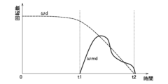
- 5 is an explanatory diagram illustrating an example of a time change in axle rotation speed and converted motor rotation speed
- FIG. 10 is an explanatory diagram illustrating an example of a comparative example of changes in axle rotation speed and converted motor rotation speed over time when a vehicle suddenly decelerates
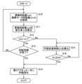
- FIG. 5 is a flowchart illustrating an example of a process of engagement control according to the embodiment.
- 10 is an explanatory diagram illustrating an example of time changes in axle rotation speed and converted motor rotation speed during rapid deceleration of a vehicle when engagement control according to an embodiment is executed
- FIG. 11 is an explanatory diagram illustrating an example of how the axle rotation speed and the converted motor rotation speed change over time when the vehicle rapidly accelerates in a case where the engagement control of the embodiment is executed.
- FIG. 1 is a schematic diagram showing a hybrid vehicle according to an embodiment.
- Hybrid vehicle 1 (hereinafter referred to as “vehicle 1”) is a plug-in hybrid (PHEV) vehicle that can run by driving front wheels 3 with the output of engine 2 (internal combustion engine), and is equipped with a front motor 4 (electric motor for driving) that drives front wheels 3.
- PHEV plug-in hybrid
- the engine 2 drives the axle 8 of the front wheels 3 via the reduction gear 7, and also drives the motor generator 9 via the reduction gear 7 to generate electricity.
- the front motor 4 is powered by the power supplied from the drive battery 11 and the motor generator 9 via the front inverter 10, and drives the axle 8 of the front wheels 3 via the reduction gear 7.
- the reduction gear 7 incorporates an engine clutch 7a that switches the transmission of power between the output shaft of the engine 2 and the axle 8, and a motor clutch 7b that switches the transmission of power between the front motor 4 and the axle 8.
- the engine clutch 7a and the motor clutch 7b (engagement devices) are wet-type multi-plate hydraulic friction engagement devices.
- the engine clutch 7a is actuated by hydraulic pressure from a hydraulic first actuator 31, and the motor clutch 7b is actuated by hydraulic pressure from a hydraulic second actuator 32.
- the engine clutch 7a and the motor clutch 7b are not limited to hydraulic types, but may be electric friction engagement devices, and are not limited to friction engagement devices, but may be meshing engagement devices.
- the vehicle 1 of this embodiment also includes a motor rotation speed detection sensor 41 that detects the rotation speed of the front motor 4, and an axle rotation speed detection sensor 42 that detects the axle rotation speed ⁇ d of the axle 8.
- the motor rotation speed detection sensor 41 and the axle rotation speed detection sensor 42 output the detection results to the hybrid control unit 20 (control device, hereinafter referred to as "HCTU 20").
- the driving battery 11 is composed of secondary batteries such as lithium ion batteries, and has a battery module (not shown) which is made up of multiple battery cells.
- the driving battery 11 is provided with a battery monitoring unit 11a which monitors the state of charge of the battery module.
- the vehicle 1 also has a charger 21 which charges the driving battery 11 externally from an external power source, and external power supply is also possible.
- HCTU20 is a control device that performs overall control of vehicle 1, and is composed of input/output devices, storage devices (ROM, RAM, non-volatile RAM, etc.), a central processing unit (CPU), etc.
- HCTU20 inputs various operation information and detection amounts detected by various sensors (not shown), such as accelerator opening, brake stroke, vehicle speed, and wheel speed.
- HCTU20 also inputs the rotation speed of front motor 4 from motor rotation speed detection sensor 41 and the axle rotation speed ⁇ d of axle 8 from axle rotation speed detection sensor 42.
- HCTU20 calculates the motor rotation speed as an axle conversion value by dividing the input rotation speed of front motor 4 by the reduction ratio of reducer 7. In the following explanation, the motor rotation speed as an axle conversion value is referred to as "converted motor rotation speed ⁇ md".
- the HCTU 20 calculates information necessary for controlling the vehicle 1, such as the required driving force required for the vehicle 1 to run, based on the various detection amounts and various operational information input. Based on the calculated information, the HCTU 20 outputs various control signals to the engine control unit 14, the front inverter 10, the reduction gear 7, etc., and controls the output of the engine 2 and the front motor 4, the output (generated power) of the motor generator 9, the operation of the first actuator 31, and the second actuator 32, etc.
- the HCTU 20 also controls the driving mode of the vehicle 1.
- the driving modes of the vehicle 1 include an EV driving mode, a series driving mode, a parallel driving mode, and an engine driving mode.
- the EV driving mode the engine 2 is stopped, and the front motor 4 is driven by power supplied from the drive battery 11 to drive the vehicle 1.
- the series driving mode the motor generator 9 is operated by the engine 2, and the front motor 4 is driven by power generated by the motor generator 9 and power supplied from the drive battery 11 to drive the vehicle 1.
- the parallel driving mode power is mechanically transmitted from the engine 2 to the axle 8 via the reduction gear 7, and the front motor 4 is driven by power generated by the motor generator 9 and power supplied from the drive battery 11 to drive the vehicle.
- the engine driving mode power is mechanically transmitted from the engine 2 to the axle 8 via the reduction gear 7 to drive the vehicle 1.
- the motor clutch 7b in the engine driving mode, the motor clutch 7b is opened by the second actuator 32, and the connection between the front motor 4 and the axle 8 is released. This reduces the load acting on the axle 8 when power from the front motor 4 is not used for driving.
- the motor clutch 7b in the EV driving mode, series driving mode, and parallel driving mode, the motor clutch 7b is engaged by the second actuator 32, and the front motor 4 and the axle 8 are connected.
- the engine driving mode in which the connection between the front motor 4 and the axle 8 is released will be referred to as the "first driving mode”
- the EV driving mode, series driving mode, and parallel driving mode in which the front motor 4 and the axle 8 are connected will be referred to as the "second driving mode”.
- the HCTU 20 switches the driving mode according to the establishment of various predetermined conditions. For example, when the vehicle speed becomes equal to or lower than a first predetermined vehicle speed while driving in the engine driving mode, the HCTU 20 shifts the driving mode to the series driving mode. Also, for example, when the vehicle speed becomes equal to or higher than a second predetermined vehicle speed that is higher than the first predetermined vehicle speed while driving in the engine driving mode, the HCTU 20 shifts the driving mode to the parallel driving mode. In this way, when the driving mode is shifted from the first driving mode (engine driving mode) to the second driving mode (EV driving mode, series driving mode, or parallel driving mode), the front motor 4 and the axle 8 are connected by engaging the motor clutch 7b. At that time, the HCTU 20 executes rotation synchronization control to synchronize the converted motor rotation speed ⁇ md of the front motor 4 with the axle rotation speed ⁇ d.
- FIG. 2 is an explanatory diagram illustrating the time change of the axle rotation speed ⁇ d and the converted motor rotation speed ⁇ md.
- the axle rotation speed ⁇ d is indicated by a dashed line
- the converted motor rotation speed ⁇ md is indicated by a solid line.
- the vehicle speed becomes equal to or lower than a first predetermined vehicle speed, and the condition for transitioning to the series driving mode is established, so that the rotation synchronization control of the converted motor rotation speed ⁇ md to the axle rotation speed ⁇ d is started at time t1.
- the rotation synchronization control is a control that drives the front motor 4 so that the converted motor rotation speed ⁇ md converges to the axle rotation speed ⁇ d by feedback control such as PID control. For example, when the difference in rotation speed between the converted motor rotation speed ⁇ md and the axle rotation speed ⁇ d remains within a predetermined range for a predetermined synchronization completion determination time, it is determined that the rotation synchronization is completed.
- the HCTU 20 determines that rotation synchronization is complete at time t2, it starts the operation of the second actuator 32 to engage the motor clutch 7b.
- the second actuator 32 operates for a predetermined operating time ta.
- the operating time ta is the time required from when it is determined that the rotation synchronization is complete until the motor clutch 7b is fully engaged, and is determined in advance taking into consideration the time for the HCTU 20 to output an operating command to the second actuator 32 and the operating delay time of the second actuator 32.
- the second actuator 32 is also configured to be able to adjust the operating time ta as appropriate.
- FIG. 3 is an explanatory diagram illustrating the time changes of the axle rotation speed ⁇ d and the converted motor rotation speed ⁇ md when the vehicle 1 suddenly decelerates as a comparative example.
- the example shown in FIG. 3 assumes a situation in which the vehicle 1 traveling in engine driving mode decelerates more rapidly than in the example shown in FIG. 2.
- rotation synchronization may not be completed by the time the vehicle 1 stops at time t2.
- the front motor 4 and the axle 8 cannot be connected by the time the vehicle 1 stops, and the vehicle 1 cannot promptly start traveling using the power of the front motor 4 when it starts moving again.
- the vehicle speed of the vehicle 1 traveling in the engine driving mode reaches or exceeds the second predetermined vehicle speed and the vehicle 1 rapidly accelerates, it may take time for the converted motor rotation speed ⁇ md to synchronize with the axle rotation speed ⁇ d, as in the example shown in FIG. 3 above, and the front motor 4 and the axle 8 may not be connected promptly. As a result, it may not be possible to obtain sufficient output in response to the driver's acceleration request.
- FIG. 4 is a flowchart showing an example of the process of the engagement control of the embodiment. The process shown in Figure 4 is executed by the HCTU 20 when the execution of the rotation synchronization control is started.
- HCTU20 first acquires the axle rotation speed ⁇ d and the converted motor rotation speed ⁇ md (step S10). Specifically, HCTU20 acquires the axle rotation speed ⁇ d detected by the axle rotation speed detection sensor 42. HCTU20 also acquires the rotation speed detected by the motor rotation speed detection sensor 41, and calculates and acquires the converted motor rotation speed ⁇ md. Next, HCTU20 calculates the rate of change ⁇ of the axle rotation speed ⁇ d per unit time (step S11). The rate of change ⁇ is a positive value when the vehicle 1 is accelerating, and a negative value when the vehicle 1 is decelerating.
- HCTU20 judges whether the absolute value of the calculated rate of change ⁇ is less than a predetermined value ⁇ 1 (step S12). That is, HCTU20 judges whether the vehicle 1 has suddenly decelerated or accelerated while the rotation synchronization control is being executed.
- the predetermined value ⁇ 1 and the above unit time may be arbitrarily set as values that can be used to judge whether the vehicle 1 is suddenly decelerating or accelerating.
- step S12 judges whether the absolute value of the rate of change ⁇ is less than the predetermined value ⁇ 1 (Yes in step S12), that is, when HCTU20 judges that the vehicle 1 is not suddenly decelerating or accelerating, it judges whether the rotation synchronization between the converted motor rotation speed ⁇ md and the axle rotation speed ⁇ d has been completed (step S13).
- HCTU20 judges that the rotation synchronization has been completed.
- step S13 When the HCTU 20 determines that rotation synchronization has not been completed (No in step S13), it repeats the processing from step S10 onwards. On the other hand, when the HCTU 20 determines that synchronization has been completed (Yes in step S13), it outputs an operation command to the second actuator 32 (step S14) and ends this routine. As a result, when the second actuator 32 completes engagement of the motor clutch 7b, the front motor 4 and the axle 8 are connected, and thereafter, the converted motor rotation speed ⁇ md and the axle rotation speed ⁇ d are equal, as shown in FIG. 2.
- the HCTU 20 determines that the absolute value of the rate of change ⁇ is equal to or greater than the predetermined value ⁇ 1 (No in step S12), i.e., when it determines that the vehicle 1 has suddenly decelerated or accelerated, it calculates the predicted arrival time ⁇ t (see FIG. 5) until the converted motor rotation speed ⁇ md and the axle rotation speed ⁇ d match (step S15).
- the predicted arrival time ⁇ t may be calculated based on the differential rotation speed between the converted motor rotation speed ⁇ md and the axle rotation speed ⁇ d, the rate of change per unit time of the converted motor rotation speed ⁇ md, and the above-mentioned rate of change ⁇ of the axle rotation speed ⁇ d. Note that in the process of step S15, the latest converted motor rotation speed ⁇ md and axle rotation speed ⁇ d are obtained at the time of execution to calculate the predicted arrival time ⁇ t.
- HCTU20 determines whether the calculated expected arrival time ⁇ t is equal to or less than the predetermined operation time ta of the second actuator 32 (step S16). When HCTU20 determines that the expected arrival time ⁇ t is greater than the operation time ta (No in step S16), it repeats the processing from step S15 onwards. On the other hand, when HCTU20 determines that the expected arrival time ⁇ t is equal to or less than the operation time ta (Yes in step S16), it outputs an operation command to the second actuator 32 (step S14) and ends this routine.
- FIG. 5 is an explanatory diagram illustrating the time change of the axle rotation speed ⁇ d and the converted motor rotation speed ⁇ md during sudden deceleration of the vehicle 1 when the engagement control of the embodiment is executed.
- the rate of change ⁇ of the axle rotation speed ⁇ d becomes equal to or exceeds a predetermined value ⁇ 1 on the deceleration side (negative side) due to sudden deceleration of the vehicle 1.
- an expected arrival time ⁇ t until the converted motor rotation speed ⁇ md and the axle rotation speed ⁇ d match is calculated, and when the expected arrival time ⁇ t becomes equal to or less than the operation time ta at time t2, an operation command is output to the second actuator 32 and the second actuator 32 starts to operate.
- the operation time ta has elapsed
- the engagement of the motor clutch 7b is completed at time t3 and the front motor 4 and the axle 8 are connected, and thereafter, the converted motor rotation speed ⁇ md and the axle rotation speed ⁇ d match as shown by the solid line.
- the dashed double-dashed line in the figure shows the behavior of the converted motor rotation speed ⁇ md when the second actuator 32 is not operated (the behavior shown in FIG. 3).
- the motor clutch 7b can be fully engaged near the point where the converted motor rotation speed ⁇ md and the axle rotation speed ⁇ d match (intersect). This makes it possible to connect the front motor 4 and the axle 8 before waiting for synchronization to be completed, while minimizing the occurrence of shock as much as possible. Therefore, the front motor 4 and the axle 8 are connected before the vehicle 1 stops, and it is possible to output the power of the front motor 4 and start traveling when restarting. Also, in this case, since the vehicle 1 is under conditions of rapid deceleration, it is considered that the impact of the shock felt by the occupants of the vehicle 1 due to the engagement of the motor clutch 7b is small.
- FIG. 6 is an explanatory diagram illustrating the time change of the axle rotation speed ⁇ d and the converted motor rotation speed ⁇ md during sudden acceleration of the vehicle 1 when the engagement control of the embodiment is executed.
- a situation is assumed in which the vehicle 1 traveling in the engine driving mode suddenly accelerates.
- the rate of change ⁇ of the axle rotation speed ⁇ d becomes equal to or exceeds a predetermined value ⁇ 1 on the acceleration side (positive side) due to the sudden acceleration of the vehicle 1, and the expected arrival time ⁇ t is calculated.
- the predetermined operation time ta may be set to a different value when the rate of change ⁇ is equal to or greater than the predetermined value ⁇ 1 and when the rate of change ⁇ is less than the predetermined value ⁇ 1. More specifically, when the rate of change ⁇ is equal to or greater than the predetermined value ⁇ 1, the predetermined operation time ta may be set to a shorter value than when the rate of change ⁇ is less than the predetermined value ⁇ 1.
- the operation time ta of the second actuator 32 is set to a shorter operation time ta2.
- the predicted arrival time ⁇ t2 when the operation time is equal to or less than ta2 will be shorter than the predicted arrival time ⁇ t described above, and as a result, the calculation accuracy of the predicted arrival time ⁇ t2 can be improved.
- the predicted arrival time ⁇ t2 and the actuator's predetermined operation time ta2 can be made to have values that are closer to each other, and the probability that the motor clutch 7b will be fully engaged when the converted motor rotation speed ⁇ md reaches the axle rotation speed ⁇ d can be increased. As a result, the occurrence of shocks can be more appropriately suppressed.
- the operation time ta of the second actuator 32 may be set to a longer time.
- the operation time ta may be adjusted appropriately depending on the calculation accuracy of the predicted arrival time ⁇ t and the magnitude of the shock caused by the speed of the engagement operation of the motor clutch 7b. In this way, by appropriately adjusting the operation time ta of the second actuator 32 when the vehicle 1 is suddenly decelerating or accelerating, the occurrence of shock caused by the connection between the front motor 4 and the axle 8 can be more appropriately suppressed.
- the connection between the front motor 4 and the axle 8 is initiated so that the predicted arrival time ⁇ t for the converted motor rotation speed ⁇ md to reach the axle rotation speed ⁇ d roughly coincides with the predetermined operation time ta of the second actuator 32.
- the front motor 4 and the axle 8 are connected near the time when the converted motor rotation speed ⁇ md reaches the axle rotation speed ⁇ d. Therefore, according to the vehicle 1, it is possible to quickly connect the front motor 4 and the axle 8 during sudden deceleration or acceleration while minimizing the occurrence of shock as much as possible.
- the present invention is applied to vehicle 1, which is a plug-in hybrid vehicle, but the present invention may be applied to any hybrid vehicle that has an internal combustion engine as a drive source and a motor for driving.
- steps S15 and S16 is executed both during sudden deceleration and sudden acceleration of the vehicle 1, i.e., when the absolute value of the rate of change ⁇ of the axle rotation speed ⁇ d is equal to or greater than the predetermined value ⁇ 1.
- the processing of steps S15 and S16 may be executed only during sudden deceleration of the vehicle 1, i.e., only when the rate of change ⁇ of the axle rotation speed ⁇ d is equal to or greater than the predetermined value ⁇ 1 on the deceleration side (negative side).
- the rotation synchronization control and the process of FIG. 4 are performed using the converted motor rotation speed ⁇ md and the axle rotation speed ⁇ d, but the rotation synchronization control and the process of FIG. 4 may also be performed using the motor converted value of the axle rotation speed ⁇ d and the rotation speed of the front motor 4.
- "synchronizing the motor rotation speed and the axle rotation speed” and “the motor rotation speed reaching the axle rotation speed” refer to the rotation speeds that take into account the gear ratio in a mechanism such as the reducer 7 that is arranged between the front motor 4 and the axle 8.
- Vehicle Hybrid vehicle
- Engine internal combustion engine
- Front motor electric motor for driving
- Reducer 7b
- Motor clutch engagement device
- Axle 20
- HCTU Hybrid Control Unit: Control Device
- Second actuator actuator
- Motor revolution speed detection sensor Axle revolution speed detection sensor ta, ta2 Operation time ⁇ Rate of change ⁇ 1 Predetermined value ⁇ t, ⁇ t2 Anticipated arrival time ⁇ d
- Axle revolution speed ⁇ md Converted motor revolution speed (motor revolution speed)
Landscapes
- Engineering & Computer Science (AREA)
- Chemical & Material Sciences (AREA)
- Combustion & Propulsion (AREA)
- Transportation (AREA)
- Mechanical Engineering (AREA)
- Automation & Control Theory (AREA)
- Electric Propulsion And Braking For Vehicles (AREA)
- Hybrid Electric Vehicles (AREA)
Abstract
車両は、フロントモータと車軸との接続が解除された状態でエンジンを駆動源として走行するエンジン走行モード(第1走行モード)から、フロントモータを駆動源として走行する第2走行モードへと切り替えるときに、換算モータ回転数ωmdと車軸回転数ωdとを同期させてからモータクラッチによりフロントモータと車軸とを接続させるように第2アクチュエータの作動を開始させるHCTU(制御装置)を備える。HCTUは、換算モータ回転数ωmdと車軸回転数ωdとの同期中に車軸回転数ωdの単位時間あたりの変化率αが所定値α1以上である場合、換算モータ回転数ωmdが車軸回転数ωdに到達するまでの予想到達時間Δtを算出し、予想到達時間Δtが第2アクチュエータの所定の動作時間ta以下となったときに、モータクラッチによりフロントモータと車軸とを接続させるように第2アクチュエータの作動を開始させる。
Description
本発明は、ハイブリッド車両に関する。
従来、駆動源としての内燃機関およびモータを備えたハイブリッド車両において、走行モードを切り換える際に、モータの回転数を当該モータが接続される部材の回転数に同期させる制御に関する技術が知られている。例えば、特許文献1には、エンジンに連結された第1回転要素と、発電機能を有する第1モータに連結された第2回転要素と、第2モータおよび出力部材に連結された第3回転要素とを有する動力分割機構と、エンジンと動力分割機構との間に設けられた変速部と、変速部をニュートラル状態または変速状態に設定する係合装置とを備えたハイブリッド車両が記載されている。このハイブリッド車両では、変速部をニュートラル状態から変速状態に切り替える際、モータの回転数を制御することによって、係合装置の差回転数が同期回転数からの差として予め定められた所定回転数以内となった場合に、モータのトルクを一定に制御した状態で係合装置の係合を開始する。
ところで、駆動源としての内燃機関およびモータを備えたハイブリッド車両では、モータと車軸とを切り離した状態で内燃機関を駆動源として走行する走行モードから、少なくともモータを駆動源として走行する走行モードへと移行する場合がある。この場合、モータを車軸に接続する際のショックを抑制するために、上述したように、走行モードの切り替えに際してモータ回転数を車軸回転数に同期する回転同期制御が実行される。
しかしながら、モータ回転数の車軸回転数への同期には時間を要するため、例えば車両が停車前に急減速した場合、車両が停車するまでに同期完了が間に合わないことがあり得る。その結果、車両の再発進時にモータの車軸への接続が完了しておらず、モータの動力を用いた走行を速やかに開始できない可能性がある。また、例えば車両が急加速した場合、モータ回転数の車軸回転数への同期に時間を要すると、運転者の加速要求に対して十分な出力を得ることができない可能性がある。このように、車両の急減速時や急加速時には、モータと車軸と接続を速やかに完了することが求められる。
本発明はこのような課題に鑑みてなされたものであり、その目的とするところは、急減速時や急加速時に、できる限りショックの発生を抑制しながら、走行用電動モータと車軸とを速やかに接続可能なハイブリッド車両を提供することにある。
上記目的を達成するため、本発明のハイブリッド車両は、内燃機関と、走行用電動モータと、前記走行用電動モータと車軸との接続および接続の解除を切り替える係合装置と、前記係合装置を動作させるアクチュエータと、前記走行用電動モータと前記車軸との接続が解除された状態で前記内燃機関を駆動源として走行する第1走行モードから、少なくとも前記走行用電動モータを駆動源として走行する第2走行モードへと切り替えるときに、モータ回転数と車軸回転数とを同期させてから前記係合装置により前記走行用電動モータと前記車軸とを接続させるように前記アクチュエータの作動を開始させる制御装置とを備え、前記制御装置は、前記モータ回転数と前記車軸回転数との同期中に前記車軸回転数の単位時間あたりの変化率の絶対値が所定値以上であるとき、前記モータ回転数および前記車軸回転数に基づいて前記モータ回転数が前記車軸回転数に到達するまでの予想到達時間を算出し、前記予想到達時間が前記アクチュエータの所定の動作時間以下となると、前記係合装置により前記走行用電動モータと前記車軸とを接続させるように前記アクチュエータの作動を開始させる。
この構成により、車軸回転数の変化率の絶対値が所定値以上であり車両が急減速や急加速をした場合には、モータ回転数が車軸回転数に到達するまでの予想到達時間とアクチュエータの所定の動作時間とが概ね一致するように、走行用電動モータと車軸との接続が開始される。その結果、モータ回転数が車軸回転数に到達する時点の近傍で走行用電動モータと車軸とが接続される。したがって、本発明のハイブリッド車両によれば、急減速時や急加速時に、できる限りショックの発生を抑制しながら、走行用電動モータと車軸とを速やかに接続することが可能となる。
また、前記所定の動作時間は、前記変化率の絶対値が前記所定値以上である場合と、前記変化率の絶対値が前記所定値未満である場合とで、異なる値に設定されることが好ましい。この構成により、車両が急減速や急加速をしている場合に、アクチュエータの動作時間を適切に調整して、走行用電動モータと車軸との接続によるショックの発生をより適切に抑制することができる。
また、前記所定の動作時間は、前記変化率の絶対値が前記所定値以上である場合、前記変化率の絶対値が所定値未満であるときに比べて短く設定されることが好ましい。この構成により、車両が急減速や急加速をしている場合に、アクチュエータの動作時間を通常時に比べて短くすることで、上記予想到達時間の算出精度を高めることができる。つまり、予想到達時間とアクチュエータの所定の動作時間とをより近似した値とし、モータ回転数が車軸回転数に到達した時点で走行用電動モータと車軸との接続が完了する確率を高めることができる。その結果、ショックの発生をより適切に抑制することができる。
また、前記制御装置は、前記モータ回転数と前記車軸回転数との同期中に前記変化率が減速側に前記所定値以上であるとき、前記予想到達時間を算出し、前記予想到達時間が前記所定の動作時間以下となると前記アクチュエータの作動を開始させることが好ましい。この構成により、走行用電動モータと車軸との接続によるショックの影響を車両の搭乗者が感じづらい急減速時において、走行用電動モータと車軸とを速やかに接続することが可能となる。
本発明のハイブリッド車両によれば、急減速時や急加速時に、できる限りショックの発生を抑制しながら、走行用電動モータと車軸とを速やかに接続可能となる。
以下、図面に基づき本発明の一実施形態について説明する。図1は、実施形態のハイブリッド車両を示す概略構成図である。ハイブリッド車両1(以下、「車両1」と称する)は、エンジン2(内燃機関)の出力によって前輪3を駆動して走行可能であると共に、前輪3を駆動するフロントモータ4(走行用電動モータ)を備えたプラグインハイブリッド(PHEV)車両である。
エンジン2は、減速機7を介して前輪3の車軸8を駆動すると共に、減速機7を介してモータジェネレータ9を駆動して発電させる。フロントモータ4は、フロントインバータ10を介して駆動用バッテリ11およびモータジェネレータ9から電力を供給されて駆動し、減速機7を介して前輪3の車軸8を駆動する。
減速機7には、エンジン2の出力軸と車軸8との間の動力の伝達を切り替えるエンジンクラッチ7aと、フロントモータ4と車軸8との間の動力の伝達を切り替えるモータクラッチ7bとが内蔵されている。エンジンクラッチ7aおよびモータクラッチ7b(係合装置)は、湿式多板式の油圧式摩擦係合装置である。エンジンクラッチ7aは、油圧式の第1アクチュエータ31からの油圧により作動し、モータクラッチ7bは、油圧式の第2アクチュエータ32からの油圧により作動する。なお、エンジンクラッチ7aおよびモータクラッチ7bは、油圧式に限らず電動式の摩擦係合装置であってもよいし、摩擦係合装置に限らず噛み合い式の係合装置であってもよい。
また、本実施形態の車両1は、フロントモータ4の回転数を検出するモータ回転数検出センサ41と、車軸8の車軸回転数ωdを検出する車軸回転数検出センサ42とを備えている。モータ回転数検出センサ41および車軸回転数検出センサ42は、検出結果をハイブリッドコントロールユニット20(制御装置。以下、「HCTU20」と称する)に出力する。
駆動用バッテリ11は、リチウムイオン電池などの二次電池で構成され、複数の電池セルをまとめて構成された図示しない電池モジュールを有する。駆動用バッテリ11には、電池モジュールの充電率(State Of Charge)などを監視するバッテリモニタリングユニット11aが設けられている。また、車両1は、駆動用バッテリ11を外部電源によって外部充電する充電機21を備え、外部給電も可能である。
HCTU20は、車両1の総合的な制御を行う制御装置であり、入出力装置、記憶装置(ROM、RAM、不揮発性RAM等)、中央演算処理装置(CPU)等を含んで構成される。HCTU20は、アクセル開度、ブレーキストローク、車速、車輪速といった図示しない各種センサにより検出される検出量や各種動作情報を入力する。また、HCTU20は、モータ回転数検出センサ41からフロントモータ4の回転数、車軸回転数検出センサ42から車軸8の車軸回転数ωdを入力する。HCTU20は、入力したフロントモータ4の回転数を減速機7の減速比で除算した車軸換算値としてのモータ回転数を算出する。以下の説明では、車軸換算値としてのモータ回転数を「換算モータ回転数ωmd」と称する。
HCTU20は、入力した各種検出量や各種動作情報などに基づいて、車両1の走行に要求される要求駆動力といった車両1の制御に必要な情報を演算する。HCTU20は、演算した情報に基づいて、エンジンコントロールユニット14、フロントインバータ10、減速機7などに各種制御信号を出力し、エンジン2およびフロントモータ4の出力、モータジェネレータ9の出力(発電電力)、第1アクチュエータ31、第2アクチュエータ32の動作などを制御する。
また、HCTU20は、車両1の走行モードを制御する。車両1の走行モードは、EV走行モード、シリーズ走行モード、パラレル走行モードおよびエンジン走行モードを含む。EV走行モードでは、エンジン2を停止し、駆動用バッテリ11から供給される電力によりフロントモータ4を駆動して車両1を走行させる。シリーズ走行モードでは、エンジン2によりモータジェネレータ9を作動し、モータジェネレータ9により発電された電力および駆動用バッテリ11から供給される電力によりフロントモータ4を駆動して車両1を走行させる。パラレル走行モードでは、エンジン2から減速機7を介して車軸8に機械的に動力を伝達すると共に、モータジェネレータ9により発電した電力や駆動用バッテリ11から供給される電力によってフロントモータ4を駆動して走行させる。また、エンジン走行モードでは、エンジン2から減速機7を介して車軸8に機械的に動力を伝達して車両1を走行させる。
本実施形態の車両1では、エンジン走行モードにおいて第2アクチュエータ32によりモータクラッチ7bが開放状態とされ、フロントモータ4と車軸8との接続が解除される。それにより、フロントモータ4からの動力を走行に用いない場合に車軸8に作用する負荷を低減している。一方で、EV走行モード、シリーズ走行モードおよびパラレル走行モードにおいては、第2アクチュエータ32によりモータクラッチ7bが係合状態とされ、フロントモータ4と車軸8とが接続される。以下、フロントモータ4と車軸8との接続が解除されるエンジン走行モードを適宜「第1走行モード」と称し、フロントモータ4と車軸8とが接続されるEV走行モード、シリーズ走行モードおよびパラレル走行モードを適宜「第2走行モード」と称する。
そして、HCTU20は、種々の所定条件の成立に応じて、上記走行モードを切り替える。HCTU20は、例えば、エンジン走行モードで走行している状態で車速が第1所定車速以下となったとき、走行モードをシリーズ走行モードに移行させる。また、HCTU20は、例えば、エンジン走行モードで走行している状態で車速が第1所定車速より大きい第2所定車速以上となったとき、走行モードをパラレル走行モードに移行させる。このように、走行モードを第1走行モード(エンジン走行モード)から第2走行モード(EV走行モード、シリーズ走行モードまたはパラレル走行モード)に移行させる場合、モータクラッチ7bの係合によりフロントモータ4と車軸8との接続が行われる。その際、HCTU20は、フロントモータ4の上記換算モータ回転数ωmdを車軸回転数ωdに同期させる回転同期制御を実行する。
図2を参照しながら回転同期制御について説明する。図2は、車軸回転数ωdと換算モータ回転数ωmdとの時間変化の様子を例示する説明図である。図2および後述する図3から図6においては、車軸回転数ωdを破線、換算モータ回転数ωmdを実線で示している。いま、エンジン走行モードで走行している車両1が減速した後、停車した状況を想定する。図示するように、車速が第1所定車速以下となり、シリーズ走行モードへの移行条件が成立したことで、時刻t1において換算モータ回転数ωmdの車軸回転数ωdへの回転同期制御が開始される。回転同期制御は、PID制御といったフィードバック制御によって換算モータ回転数ωmdが車軸回転数ωdに収束するようにフロントモータ4を駆動する制御であり、例えば換算モータ回転数ωmdと車軸回転数ωdとの差回転数が所定範囲内の状態が所定の同期完了判定時間にわたって継続した場合に回転同期が完了したと判定される。
HCTU20は、時刻t2において回転同期が完了したと判定すると、モータクラッチ7bの係合させるように第2アクチュエータ32の作動を開始させる。このとき、第2アクチュエータ32は、所定の動作時間taで動作する。動作時間taは、上記回転同期が完了したと判定してからモータクラッチ7bが完全係合するまでに要する時間であり、HCUT20から第2アクチュエータ32への作動指示を出力する時間や第2アクチュエータ32の動作遅れ時間などを考慮して予め定められる。また、第2アクチュエータ32は、適宜、動作時間taを調整可能に構成されている。
それにより、時刻t3においてモータクラッチ7bが完全係合してフロントモータ4と車軸8とが接続され、以降は、実線で示すように換算モータ回転数ωmdと車軸回転数ωdが一致した値となる。このように、時刻t4において車両1の停車が完了する前にフロントモータ4と車軸8とを接続しておくことで、車両1が再発進する際に、EV走行モードやシリーズ走行モードでフロントモータ4の動力を用いた走行を速やかに開始することができる。
これに対して、図3は、比較例としての車両1の急減速時における車軸回転数ωdと換算モータ回転数ωmdとの時間変化の様子を例示する説明図である。図3に示す例では、エンジン走行モードで走行している車両1が図2に示す例よりも急減速した状況を想定している。この場合、時刻t1で回転同期制御が開始された後、換算モータ回転数ωmdが車軸回転数ωdに収束するようにフロントモータ4を駆動制御しても、時刻t2での車両1の停車までに回転同期が完了しないことがあり得る。その結果、車両1が停車するまでにフロントモータ4と車軸8とを接続することができず、車両1が再発進する際にフロントモータ4の動力を用いた走行を速やかに開始できなくなってしまう。
また、例えばエンジン走行モードで走行している車両1の車速が第2所定車速以上となったことでパラレル走行モードへと移行する場合に、車両1が急加速していると、上記図3に示した例と同様に換算モータ回転数ωmdの車軸回転数ωdへの同期に時間を要してしまい、フロントモータ4と車軸8とを速やかに接続することができない可能性がある。その結果、運転者の加速要求に対して十分な出力を得ることができない。
以上のように、車両1の急減速時や急加速時には、フロントモータ4の車軸8への接続を速やかに完了することが求められる。そこで、実施形態の車両1は、以下に説明するモータクラッチ7bの係合制御を実行する。図4は、実施形態の係合制御の処理の一例を示すフローチャートである。図4に示す処理は、回転同期制御が実行開始されたとき、HCTU20により実行される。
HCTU20は、まず、車軸回転数ωdと換算モータ回転数ωmdとを取得する(ステップS10)。具体的には、HCTU20は、車軸回転数検出センサ42で検出された車軸回転数ωdを取得する。また、HCTU20は、モータ回転数検出センサ41で検出された回転数を取得し、上記換算モータ回転数ωmdを算出して取得する。次に、HCTU20は、車軸回転数ωdの単位時間あたりの変化率αを算出する(ステップS11)。変化率αは、車両1が加速している場合に正の値となり、車両1が減速している場合に負の値となる。
次に、HCTU20は、算出した変化率αの絶対値が所定値α1未満であるか否かを判定する(ステップS12)。すなわち、HCTU20は、回転同期制御の実行中に車両1が急減速または急加速したか否かを判定する。所定値α1や上記単位時間は、車両1が急減速や急加速をしていると判断可能な値として任意に定められればよい。そして、HCTU20は、変化率αの絶対値が所定値α1未満であると判定したとき(ステップS12でYes)、すなわち、車両1が急減速または急加速していないと判定したとき、換算モータ回転数ωmdと車軸回転数ωdとの回転同期が完了したか否かを判定する(ステップS13)。HCTU20は、上述したように、換算モータ回転数ωmdと車軸回転数ωdとの差回転数が所定範囲内の状態が所定の同期完了判定時間にわたって継続した場合、回転同期が完了したと判定する。
HCTU20は、回転同期が完了していないと判定したとき(ステップS13でNo)、ステップS10以降の処理を繰り返し実行する。一方、HCTU20は、同期が完了したと判定したとき(ステップS13でYes)、第2アクチュエータ32へと作動指示を出力し(ステップS14)、本ルーチンを終了する。これにより、第2アクチュエータ32によりモータクラッチ7bの係合が完了すると、フロントモータ4と車軸8とが接続され、以降は、図2に例示したように換算モータ回転数ωmdと車軸回転数ωdとが一致した状態となる。
これに対して、HCTU20は、変化率αの絶対値が所定値α1以上であると判定したとき(ステップS12でNo)、すなわち、車両1が急減速または急加速したと判定したとき、換算モータ回転数ωmdと車軸回転数ωdとが一致するまでの予想到達時間Δt(図5参照)を算出する(ステップS15)。予想到達時間Δtは、換算モータ回転数ωmdと車軸回転数ωdとの差回転数、換算モータ回転数ωmdの単位時間あたりの変化率および車軸回転数ωdの上記変化率αに基づいて算出さればよい。なお、ステップS15の処理では、実行時点で最新の換算モータ回転数ωmdと車軸回転数ωdとを取得して予想到達時間Δtを算出する。
次に、HCTU20は、算出した予想到達時間Δtが第2アクチュエータ32の所定の動作時間ta以下であるか否かを判定する(ステップS16)。HCTU20は、予想到達時間Δtが動作時間taよりも大きいと判定したとき(ステップS16でNo)、ステップS15以降の処理を繰り返し実行する。一方、HCTU20は、予想到達時間Δtが動作時間ta以下であると判定したとき(ステップS16でYes)、第2アクチュエータ32へと作動指示を出力し(ステップS14)、本ルーチンを終了する。
実施形態の係合制御の作用について、図5および図6を参照しながら詳細に説明する。まず、図5は、実施形態の係合制御を実行した場合の車両1の急減速時における車軸回転数ωdと換算モータ回転数ωmdとの時間変化の様子を例示する説明図である。いま、時刻t1で回転同期制御が開始された後、車両1の急減速により車軸回転数ωdの変化率αが減速側(負側)に所定値α1以上となったとする。それにより、換算モータ回転数ωmdと車軸回転数ωdとが一致するまでの予想到達時間Δtが算出され、時刻t2で予想到達時間Δtが動作時間ta以下となると、第2アクチュエータ32に作動指示が出力されて第2アクチュエータ32が作動を開始する。その結果、動作時間taが経過すると、時刻t3でモータクラッチ7bの係合が完了してフロントモータ4と車軸8とが接続され、以降は、実線で示すように換算モータ回転数ωmdと車軸回転数ωdとが一致した値となる。なお、図中の二点鎖線は、第2アクチュエータ32を作動させなかった場合の換算モータ回転数ωmdの挙動(図3に例示した挙動)を示している。
このように、予想到達時間Δtが動作時間ta以下となった時点で第2アクチュエータ32の作動を開始させることにより、換算モータ回転数ωmdと車軸回転数ωdとが一致する(交差する)時点の近傍でモータクラッチ7bを完全係合させることができる。それにより、できる限りショックの発生を抑制しつつ、同期完了を待つ前にフロントモータ4と車軸8とを接続することができる。したがって、車両1の停車前にフロントモータ4と車軸8とが接続されており、再発進時にフロントモータ4の動力を出力して走行を開始することが可能となる。また、この場合、車両1が急減速している条件下であるため、モータクラッチ7bの係合により車両1の搭乗者が感じるショックの影響は小さいと考えられる。
次に、図6は、実施形態の係合制御を実行した場合の車両1の急加速時における車軸回転数ωdと換算モータ回転数ωmdとの時間変化の様子を例示する説明図である。図6に示す例では、エンジン走行モードで走行している車両1が急加速した状況を想定している。この場合も、時刻t1で回転同期制御が開始された後、車両1の急加速により車軸回転数ωdの変化率αが加速側(正側)に所定値α1以上となり、予想到達時間Δtが算出される。そして、時刻t2で予想到達時間Δtが動作時間ta以下となると、第2アクチュエータ32に作動指示が出力されて第2アクチュエータ32が作動を開始する。その結果、換算モータ回転数ωmdと車軸回転数ωdとが一致する(交差する)時点の近傍でモータクラッチ7bが完全係合する。これにより、できる限りショックの発生を抑制しつつ、同期完了を待つ前にフロントモータ4と車軸8とを接続することができ、フロントモータ4の動力を速やかに出力して運転者の加速要求に応えることが可能となる。また、この場合、換算モータ回転数ωmdと車軸回転数ωdとの双方が増加側に変化していることから、回転同期が完了していない状態でモータクラッチ7bを係合させたとしても、運転者が感じるショックの影響は小さいと考えられる。
ここで、図5および図6では、予想到達時間Δtと第2アクチュエータ32の所定の動作時間taとが一致した例を記載しているが、実際には予想到達時間Δtと動作時間taとの間には誤差が生じ得る。そのため、換算モータ回転数ωmdが車軸回転数ωdに到達した時点(時刻t3)でモータクラッチ7bが完全係合するとは限らない。そこで、予想到達時間Δtと動作時間taとの間に生じる誤差を小さくするために、所定の動作時間taを、変化率αが所定値α1以上である場合と変化率αが所定値α1未満である場合とで異なる値に設定してもよい。より詳細には、所定の動作時間taは、変化率αが所定値α1以上である場合、変化率αが所定値α1未満であるときに比べて短く設定されてもよい。
いま、図5に例示するように、変化率αが所定値α1以上である場合に、第2アクチュエータ32の動作時間taをより短い動作時間ta2に設定したとする。この場合、動作時間ta2以下となったときの予想到達時間Δt2は、上述した予想到達時間Δtよりも短くなり、その結果として予想到達時間Δt2の算出精度を高めることができる。つまり、予想到達時間Δt2とアクチュエータの所定の動作時間ta2とをより近似した値とし、換算モータ回転数ωmdが車軸回転数ωdに到達した時点でモータクラッチ7bが完全係合する確率を高めることができる。その結果、ショックの発生をより適切に抑制することができる。
また、第2アクチュエータ32を緩やかに動作させた方がショックの発生を抑制できる場合には、第2アクチュエータ32の動作時間taをより長い時間に設定してもよい。つまり、動作時間taは、予想到達時間Δtの算出精度およびモータクラッチ7bの係合動作の速度によるショックの大きさに応じて、適宜調整されてもよい。このように、車両1が急減速や急加速をしている場合に、第2アクチュエータ32の動作時間taを適切に調整することで、フロントモータ4と車軸8との接続によるショックの発生をより適切に抑制することができる。
以上説明したように、実施形態の車両1では、車軸回転数ωdの変化率αが所定値α1以上であり車両1が急減速や急加速をした場合、換算モータ回転数ωmdが車軸回転数ωdに到達するまでの予想到達時間Δtと第2アクチュエータ32の所定の動作時間taとが概ね一致するように、フロントモータ4と車軸8との接続が開始される。その結果、換算モータ回転数ωmdが車軸回転数ωdに到達する時点の近傍でフロントモータ4と車軸8とが接続される。したがって、車両1によれば、急減速時や急加速時に、できる限りショックの発生を抑制しながら、フロントモータ4と車軸8とを速やかに接続することが可能となる。
以上で実施形態の説明を終えるが、本発明の態様はこの実施形態に限定されるものではない。例えば、本実施形態では、プラグインハイブリッド車両としての車両1に本発明を適用するものとしたが、本発明は、駆動源としての内燃機関と走行用のモータとを備えるハイブリッド車両に適用されればよい。
また、本実施形態では、車両1の急減速時および急加速時の双方において、すなわち、車軸回転数ωdの変化率αの絶対値が所定値α1以上であるときにステップS15、S16の処理を実行するものとした。ただし、車両1の急減速時のみ、すなわち、車軸回転数ωdの変化率αが減速側(負側)に所定値α1以上であるときのみに、ステップS15、S16の処理を実行するものとしてもよい。この構成により、上述したように、フロントモータ4と車軸8との接続によるショックの影響を車両1の搭乗者が感じづらい急減速時において、フロントモータ4と車軸8とを速やかに接続することが可能となる。
また、本実施形態では、換算モータ回転数ωmdと車軸回転数ωdとを用いて回転同期制御や図4の処理を実行するものとしたが、車軸回転数ωdのモータ換算値とフロントモータ4の回転数とを用いて回転同期制御や図4の処理を実行するものとしてもよい。つまり、「モータ回転数と車軸回転数とを同期させる」、「モータ回転数が車軸回転数に到達する」とは、フロントモータ4と車軸8との間に配置される減速機7といった機構での変速比を考慮した回転数同士を対象とするものである。
1 車両(ハイブリッド車両)
2 エンジン(内燃機関)
4 フロントモータ(走行用電動モータ)
7 減速機
7b モータクラッチ(係合装置)
8 車軸
20 HCTU(ハイブリッドコントロールユニット:制御装置)
32 第2アクチュエータ(アクチュエータ)
41 モータ回転数検出センサ
42 車軸回転数検出センサ
ta、ta2 動作時間
α 変化率
α1 所定値
Δt、Δt2 予想到達時間
ωd 車軸回転数
ωmd 換算モータ回転数(モータ回転数)
2 エンジン(内燃機関)
4 フロントモータ(走行用電動モータ)
7 減速機
7b モータクラッチ(係合装置)
8 車軸
20 HCTU(ハイブリッドコントロールユニット:制御装置)
32 第2アクチュエータ(アクチュエータ)
41 モータ回転数検出センサ
42 車軸回転数検出センサ
ta、ta2 動作時間
α 変化率
α1 所定値
Δt、Δt2 予想到達時間
ωd 車軸回転数
ωmd 換算モータ回転数(モータ回転数)
Claims (4)
- 内燃機関と、
走行用電動モータと、
前記走行用電動モータと車軸との接続および接続の解除を切り替える係合装置と、
前記係合装置を動作させるアクチュエータと、
前記走行用電動モータと前記車軸との接続が解除された状態で前記内燃機関を駆動源として走行する第1走行モードから、少なくとも前記走行用電動モータを駆動源として走行する第2走行モードへと切り替えるときに、モータ回転数と車軸回転数とを同期させてから前記係合装置により前記走行用電動モータと前記車軸とを接続させるように前記アクチュエータの作動を開始させる制御装置とを備え、
前記制御装置は、
前記モータ回転数と前記車軸回転数との同期中に前記車軸回転数の単位時間あたりの変化率の絶対値が所定値以上であるとき、前記モータ回転数および前記車軸回転数に基づいて前記モータ回転数が前記車軸回転数に到達するまでの予想到達時間を算出し、前記予想到達時間が前記アクチュエータの所定の動作時間以下となると、前記係合装置により前記走行用電動モータと前記車軸とを接続させるように前記アクチュエータの作動を開始させるハイブリッド車両。 - 前記所定の動作時間は、前記変化率の絶対値が前記所定値以上である場合と、前記変化率の絶対値が前記所定値未満である場合とで、異なる値に設定される請求項1に記載のハイブリッド車両。
- 前記所定の動作時間は、前記変化率の絶対値が前記所定値以上である場合、前記変化率の絶対値が前記所定値未満であるときに比べて短く設定される請求項2に記載のハイブリッド車両。
- 前記制御装置は、前記モータ回転数と前記車軸回転数との同期中に前記変化率が減速側に前記所定値以上であるとき、前記予想到達時間を算出し、前記予想到達時間が前記所定の動作時間以下となると前記アクチュエータの作動を開始させる請求項1から請求項3のいずれか一項に記載のハイブリッド車両。
Priority Applications (2)
| Application Number | Priority Date | Filing Date | Title |
|---|---|---|---|
| PCT/JP2023/011881 WO2024201581A1 (ja) | 2023-03-24 | 2023-03-24 | ハイブリッド車両 |
| JP2025509221A JPWO2024201581A1 (ja) | 2023-03-24 | 2023-03-24 |
Applications Claiming Priority (1)
| Application Number | Priority Date | Filing Date | Title |
|---|---|---|---|
| PCT/JP2023/011881 WO2024201581A1 (ja) | 2023-03-24 | 2023-03-24 | ハイブリッド車両 |
Publications (1)
| Publication Number | Publication Date |
|---|---|
| WO2024201581A1 true WO2024201581A1 (ja) | 2024-10-03 |
Family
ID=92904025
Family Applications (1)
| Application Number | Title | Priority Date | Filing Date |
|---|---|---|---|
| PCT/JP2023/011881 Ceased WO2024201581A1 (ja) | 2023-03-24 | 2023-03-24 | ハイブリッド車両 |
Country Status (2)
| Country | Link |
|---|---|
| JP (1) | JPWO2024201581A1 (ja) |
| WO (1) | WO2024201581A1 (ja) |
Citations (3)
| Publication number | Priority date | Publication date | Assignee | Title |
|---|---|---|---|---|
| JP2008155831A (ja) * | 2006-12-25 | 2008-07-10 | Toyota Motor Corp | 車両用駆動装置の制御装置 |
| JP2012066609A (ja) * | 2010-09-21 | 2012-04-05 | Toyota Motor Corp | 車両用駆動制御装置 |
| JP2018083509A (ja) * | 2016-11-22 | 2018-05-31 | トヨタ自動車株式会社 | 車両の制御装置 |
-
2023
- 2023-03-24 JP JP2025509221A patent/JPWO2024201581A1/ja active Pending
- 2023-03-24 WO PCT/JP2023/011881 patent/WO2024201581A1/ja not_active Ceased
Patent Citations (3)
| Publication number | Priority date | Publication date | Assignee | Title |
|---|---|---|---|---|
| JP2008155831A (ja) * | 2006-12-25 | 2008-07-10 | Toyota Motor Corp | 車両用駆動装置の制御装置 |
| JP2012066609A (ja) * | 2010-09-21 | 2012-04-05 | Toyota Motor Corp | 車両用駆動制御装置 |
| JP2018083509A (ja) * | 2016-11-22 | 2018-05-31 | トヨタ自動車株式会社 | 車両の制御装置 |
Also Published As
| Publication number | Publication date |
|---|---|
| JPWO2024201581A1 (ja) | 2024-10-03 |
Similar Documents
| Publication | Publication Date | Title |
|---|---|---|
| JP4562195B2 (ja) | ハイブリッド電気自動車の変速制御装置 | |
| KR101360060B1 (ko) | 하이브리드 차량의 시동모터 고장시 엔진 시동 제어 방법 및 시스템 | |
| JP5338743B2 (ja) | ハイブリッド自動車 | |
| JP6156243B2 (ja) | ハイブリッド車両の制御装置 | |
| CN103492250B (zh) | 车辆控制装置 | |
| KR101393562B1 (ko) | 하이브리드 차량의 주행 모드 변환 제어 방법 및 시스템 | |
| KR102935115B1 (ko) | 전기자동차의 사륜구동 전환 제어 시스템 및 방법 | |
| JP2000343965A (ja) | ハイブリッド車両 | |
| JPWO2009069637A1 (ja) | ハイブリッドシステムの制御方法 | |
| JP3566142B2 (ja) | ハイブリッド車両の制御装置 | |
| CN112660099A (zh) | 混合动力车辆的驱动控制装置 | |
| KR20140146907A (ko) | 하이브리드 자동차의 배터리 방전 파워 제한시 주행모드 변환 방법 및 시스템 | |
| JP2011061945A (ja) | 電気自動車の車輪スリップ制御装置 | |
| KR102648823B1 (ko) | 하이브리드 차량의 엔진 시동 방법 및 장치 | |
| JP3585392B2 (ja) | ハイブリッド車両 | |
| WO2024201581A1 (ja) | ハイブリッド車両 | |
| KR100980966B1 (ko) | 하이브리드 차량의 변속 방법 | |
| EP4316897B1 (en) | Vehicle drive device | |
| WO2020153429A1 (ja) | 車両用駆動装置及びハイブリッド車両 | |
| JP2010158973A (ja) | 車両用駆動装置の制御方法および制御装置 | |
| JP6145968B2 (ja) | ハイブリッドシステム | |
| JP5685887B2 (ja) | ハイブリッド車両の制御装置 | |
| KR20170119534A (ko) | 마일드 하이브리드 차량용 크루즈 제어 방법 및 장치 | |
| JP2001322540A (ja) | 車両用減速度制御装置 | |
| JP2010179845A (ja) | ハイブリッド車両の駆動制御装置及び駆動制御方法 |
Legal Events
| Date | Code | Title | Description |
|---|---|---|---|
| 121 | Ep: the epo has been informed by wipo that ep was designated in this application |
Ref document number: 23930222 Country of ref document: EP Kind code of ref document: A1 |
|
| WWE | Wipo information: entry into national phase |
Ref document number: 2025509221 Country of ref document: JP |
|
| NENP | Non-entry into the national phase |
Ref country code: DE |
|
| 122 | Ep: pct application non-entry in european phase |
Ref document number: 23930222 Country of ref document: EP Kind code of ref document: A1 |