WO2024189822A1 - 車両用フレーム - Google Patents
車両用フレーム Download PDFInfo
- Publication number
- WO2024189822A1 WO2024189822A1 PCT/JP2023/010077 JP2023010077W WO2024189822A1 WO 2024189822 A1 WO2024189822 A1 WO 2024189822A1 JP 2023010077 W JP2023010077 W JP 2023010077W WO 2024189822 A1 WO2024189822 A1 WO 2024189822A1
- Authority
- WO
- WIPO (PCT)
- Prior art keywords
- vehicle
- wall
- gusset
- bulkhead
- disposed
- Prior art date
- Legal status (The legal status is an assumption and is not a legal conclusion. Google has not performed a legal analysis and makes no representation as to the accuracy of the status listed.)
- Ceased
Links
Images


Classifications
-
- B—PERFORMING OPERATIONS; TRANSPORTING
- B62—LAND VEHICLES FOR TRAVELLING OTHERWISE THAN ON RAILS
- B62D—MOTOR VEHICLES; TRAILERS
- B62D21/00—Understructures, i.e. chassis frame on which a vehicle body may be mounted
- B62D21/07—Understructures, i.e. chassis frame on which a vehicle body may be mounted wide-hipped frame type, i.e. a wide box-shaped mid portion with narrower sections extending from said mid portion in both fore and aft directions
-
- B—PERFORMING OPERATIONS; TRANSPORTING
- B62—LAND VEHICLES FOR TRAVELLING OTHERWISE THAN ON RAILS
- B62D—MOTOR VEHICLES; TRAILERS
- B62D21/00—Understructures, i.e. chassis frame on which a vehicle body may be mounted
- B62D21/15—Understructures, i.e. chassis frame on which a vehicle body may be mounted having impact absorbing means, e.g. a frame designed to permanently or temporarily change shape or dimension upon impact with another body
- B62D21/152—Front or rear frames
Definitions
- the present invention relates to a vehicle frame.
- a vehicle frame structure that has a pair of side rails that extend along the front-to-rear direction of the vehicle, the widthwise spacing at the front of the vehicle is narrower than at the rear, and a bent portion is provided between the front and rear of the vehicle, a cab mount bracket that is provided at the bent portion and protrudes outward in the vehicle width direction, a load transfer member that is provided within the side rails and has a front wall that is arranged along the front side of the vehicle width direction, the front wall overlapping the rear part of the cab mount bracket when the vehicle is viewed from the side, and a cross member that is spanned across the pair of side rails, is arranged behind the cab mount bracket, and overlaps with the load transfer member when the vehicle is viewed from the side (Patent Document 1).
- the portion of the side rail where the cab mount bracket is installed is more rigid than other portions of the side rail and is less likely to deform. Therefore, in the above conventional technology, in a full-wrap collision in which the collision load is input to the front end of the side rail (also called the side frame), a part of the side rail does not deform in the fore-and-aft direction of the vehicle, and the collision energy cannot be efficiently absorbed.
- the problem that this invention aims to solve is to provide a vehicle frame that can efficiently absorb the collision energy input to the vehicle.
- the present invention solves the above problem in a vehicle frame that includes a side frame, a cab mount bracket attached to the side frame so as to protrude outward in the width direction of the vehicle, and a gusset that is fixed to the rear side of the vehicle of the cab mount bracket and faces the side frame by not connecting the gusset to the side frame.
- the present invention allows collision energy input to a vehicle to be efficiently absorbed.
- FIG. 1 is a plan view illustrating an example of a vehicle frame according to an embodiment of the present invention.
- FIG. 2 is a side view of the vehicle frame shown in FIG.
- FIG. 2 is a perspective view of a main portion of the vehicle frame shown in FIG. 1 .
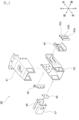
- FIG. 4 is an exploded perspective view of the gusset shown in FIG. 3 .
- FIG. 4 is an exploded perspective view of the cab mount bracket shown in FIG. 3 .
- FIG. 2 is an exploded perspective view of the bulkhead shown in FIG. 1 .
- 2 is a plan view showing the action of the vehicle frame shown in FIG. 1 in absorbing collision energy in a full-overlap collision.
- FIG. FIG. 2 is a plan view (part 1) showing the action of the vehicle frame shown in FIG. 1 in absorbing collision energy in a small overlap collision.
- FIG. 2 is a plan view (part 2) showing the effect of the vehicle frame shown in FIG. 1 in absorbing collision energy in a small overlap collision.
- FIG. 1 is a plan view showing an example of a vehicle frame according to an embodiment of the present invention.
- the frame 1 shown in Fig. 1 is a framework-like structure located under the vehicle body and mainly supporting the vehicle body.
- the vehicle according to this embodiment is a vehicle equipped with a ladder frame like the frame 1 shown in Fig. 1, and is, for example, a cargo vehicle including a pickup truck, a sports utility vehicle (SUV), etc.
- the vehicle body is a general term for the body shell, the driver's cab, the functional parts of the vehicle body, the loading platform, etc.
- the body shell refers to the box-shaped structure that makes up the passenger compartment, luggage compartment, engine compartment, etc., and includes doors, hood, trunk lid, etc.
- the driver's cab refers to the structure that makes up the passenger compartment, engine compartment, etc., and is in its completed state as an equipment with all fittings attached.
- Body functional parts refer to the mechanical components that open and close the doors and windows, and include window glass, weather strips, etc.
- the cargo bed refers to the structure that holds cargo.
- the frame 1 shown in FIG. 1 has a structure on the front side of the vehicle for absorbing collision energy input to the vehicle.
- the frame 1 has a side frame 10, a first cross member 20, a second cross member 30, a cab mount bracket 40, a gusset 50, and a bulkhead 60.
- These components are manufactured from steel plates such as high-strength steel plates.
- the side frame 10 is a component that supports the body shell as well as the engine and its accessories, which are heavy objects, and extends in the fore-and-aft direction of the vehicle at the front of the vehicle (specifically, at a position forward of the passenger compartment).
- the side frames 10 are disposed on both the right and left sides of the vehicle. In other words, a pair of side frames 10, 10 are disposed on one vehicle, as shown in Figure 1.
- the side frames 10 are also called side members.
- the cross section of the side frame 10 perpendicular to the front-to-rear direction of the vehicle has a bag structure.
- the cross section of the side frame 10 is a closed cross section.
- the side frame 10 is manufactured, for example, by joining two parts press-formed into a U-shape by spot welding or the like. There are no particular limitations on the shape of the side frame 10, so long as it is within a range that can adequately support the vehicle body.
- the side frame 10 has weak parts 11-14 that induce crushing in the longitudinal direction of the vehicle when a collision load is input in a full-overlap collision.
- the weak parts include beads and notches.
- the positions at which the weak parts are provided are not particularly limited, but for example, as shown in FIG. 1, the weak parts are provided on the front and rear sides of the cab mount bracket 40. Alternatively, the weak parts may be provided on the front or rear sides of the cab mount bracket 40.
- FIG. 1 which is a plan view
- the lower side of the side frame 10 is provided with weak parts at positions corresponding to the positions of the weak parts provided on the upper side of the side frame 10.
- FIG. 2 which is a side view
- a weak part 15 is provided at a position corresponding to the upper weak part 11
- a weak part 16 is provided at a position corresponding to the upper weak part 13.
- the first cross member 20 and the second cross member 30, like the side frame 10 are components that support the engine and its accessories as well as the body shell, and extend in the width direction of the vehicle to connect the pair of side frames 10, 10. As shown in FIG. 1, the first cross member 20 is attached to the front ends of the pair of side frames 10, 10 so as to bridge the two ends, and the second cross member 30 is attached to the rear ends of the pair of side frames 10, 10 so as to bridge the two ends.
- the cross sections of the first cross member 20 and the second cross member 30 perpendicular to the width direction of the vehicle have a bag structure.
- the cross sections of the first cross member 20 and the second cross member 30 are closed cross sections.
- the shape of the first cross member 20 and the second cross member 30 is not particularly limited as long as it is within a range that can adequately support the vehicle body.
- the second cross member 30 will also be simply referred to as the cross member 30.
- the cab mount bracket 40 shown enlarged in the lower left of Figure 1, is a component that supports the vehicle body that is attached above it, and has a mount portion M for providing a cab mount (not shown).
- the cab mount bracket 40 is attached to the side frame 10 by welding or the like so that it protrudes outward in the width direction of the vehicle.
- the cab mount bracket 40 located on the left side of the vehicle in Figure 1 is attached so that it protrudes to the left from the side frame 10 located on the left side of the vehicle.
- the shape and attachment position of the cab mount bracket 40 can be set as appropriate within a range that allows the vehicle body to be appropriately supported.
- the gusset 50 shown enlarged in the lower left of Figure 1, is a part that reinforces the cab mount bracket 40, and is attached to the rear side of the vehicle of the cab mount bracket 40.
- the gusset 50 shown in Figure 1 is fixed to the rear side of the vehicle of the cab mount bracket 40 with a bolt.
- the gusset 50 may also be fixed to the cab mount bracket 40 by welding or the like. Note that fixing the gusset 50 to the cab mount bracket 40 means that the gusset 50 is fixed in a fixed position relative to the cab mount bracket 40 so that it does not move.
- the gusset 50 in this embodiment is fixed to the cab mount bracket 40 but is not connected to the side frame 10.
- the gusset 50 is fixed to the rear side of the cab mount bracket 40 and is not connected to the side frame 10.
- connecting the gusset 50 to the side frame 10 means stopping the gusset 50 in a fixed position relative to the side frame 10 so that it does not move, and includes welding the gusset 50 to the side frame 10, attaching the gusset 50 to the side frame 10 with bolts or adhesive, and attaching the gusset 50 to the side frame 10 via parts such as stays.
- the gusset 50 and the side frame 10 are spaced apart from each other, and the gusset 50 is disposed to face the side frame 10 at a specified distance.
- the specified distance between the gusset 50 and the side frame 10 is a distance at which the rear end of the gusset 50 contacts the side frame 10 when a collision load is input to the cab mount bracket 40, and at which the gusset 50 does not inhibit deformation of the side frame 10 (specifically, crushing in the fore-aft direction of the vehicle) when a collision load is input to the side frame 10; for example, this distance is 5 to 40 mm.
- the bulkhead 60 shown enlarged in the lower left of FIG. 1, is a part that reinforces the joint between the side frame 10 and the second cross member 30, and is provided inside the side frame 10.
- the side frame 10 has a bag-like structure in cross section perpendicular to the longitudinal direction of the vehicle, and has a cavity inside, so that a part such as the bulkhead 60 can be provided inside.
- the bulkhead 60 is disposed in a position near the second cross member 30 inside the side frame 10, as shown enlarged in the lower left of FIG. 1, in order to reinforce the joint between the side frame 10 and the second cross member 30.
- the shape of the bulkhead 60 can be any shape that appropriately reinforces the joint described above and can be accommodated inside the side frame 10.
- FIG. 2 is a side view of the frame 1 shown in FIG. 1.
- the bulkhead 60 overlaps with the second cross member 30 in the fore-and-aft direction of the vehicle.
- the bulkhead 60 and the second cross member 30 are projected onto a projection plane parallel to the fore-and-aft direction of the vehicle, at least a portion of the shadow of the bulkhead 60 and the shadow of the second cross member 30 overlap on the projection plane.
- the rear end E of the gusset 50 overlaps with the bulkhead 60 in the fore-and-aft direction of the vehicle when the vehicle is viewed from the side.
- the gusset 50 and the bulkhead 60 are projected onto a projection plane parallel to the fore-and-aft direction of the vehicle, at least a portion of the shadow of the gusset 50 and the shadow of the bulkhead 60 overlap on the projection plane.
- Figure 3 is a perspective view of the main parts of the frame 1 shown in Figure 1, seen from the upper left rear of the vehicle.
- the gusset 50 is composed of a first gusset part 51, which is the main body of the gusset, a second gusset part 52 that reinforces the first gusset part 51, and a third gusset part 53 that closes the opening of the first gusset part 51.
- FIG. 4 is an exploded perspective view of the gusset 50 shown in FIG. 3.
- the shape of the first gusset part 51 is, for example, a right triangle in which the front-rear side and the width side of the vehicle form a right angle when viewed from above.
- the first gusset part 51 is provided with a hole H1 through which the bolt B1 passes, a hole H2 through which the bolt B2 passes, a hole H3 through which the bolt B3 passes, a hole H7 through which the bolt B4 passes, and a hole H8 through which the bolt B5 passes.
- the first gusset part 51 is provided with holes (not shown) at positions corresponding to the holes H1, H2, and H3 on the opposite side of the holes H1, H2, and H3 (i.e., the lower side of the vehicle).
- the second gusset part 52 has a shape that reinforces the mounting portion where the first gusset part 51 is mounted to the cab mount bracket 40, and like the first gusset part 51, is provided with a hole H4 through which bolt B1 passes, a hole H5 through which bolt B2 passes, a hole H6 through which bolt B3 passes, a hole H9 through which bolt B4 passes, and a hole H10 through which bolt B5 passes.
- holes are provided on the opposite side of holes H4, H5, and H6 (i.e., the underside of the vehicle) at positions corresponding to holes H4, H5, and H6, respectively.
- the first gusset part 51, the second gusset part 52, and the third gusset part 53 are manufactured, for example, by press forming a steel plate.
- the third gusset part 53 is welded to the side frame 10 side of the first gusset part 51, and the second gusset part 52 is placed over the first gusset part 51 to which the third gusset part 53 is welded, and then fixed to the cab mount bracket 40 by bolts B1 to B5.
- the bolts B1, B2, and B3 pass through the third bracket parts 43a, 43b, and 43c of the cab mount bracket 40, respectively, and are fixed by nuts N1, N2, and N3.
- the bolts B4 and B5 are fixed by nuts N4 and N5 provided on the cab mount bracket 40, respectively.
- the shape of the gusset 50 is not particularly limited as long as it has a predetermined distance from the side frame 10 and at least a portion of the rear end E shown in FIG. 2 overlaps with the bulkhead 60 in the fore-and-aft direction of the vehicle when viewed from the side.
- the cab mount bracket 40 is formed by joining a first bracket part 41 and a second bracket part 42 by welding or the like. Both the first bracket part 41 and the second bracket part 42 are press-formed parts whose cross section perpendicular to the width direction of the vehicle is U-shaped, with the cross section of the first bracket part 41 opening downward and the cross section of the second bracket part 42 opening upward.
- Figure 5 is an exploded perspective view of the cab mount bracket 40 shown in Figure 3.
- the first bracket part 41 and the second bracket part 42 are press-formed products having a U-shaped cross section as shown in Figure 4, for example, and can be shaped appropriately within the range in which the cab mount bracket 40 can be fixed to the side frame 10 and the gusset 50 can be fixed to the cab mount bracket 40.
- the third bracket parts 43a, 43b, and 43c are sleeves through which the bolts B1, B2, and B3 pass, respectively, and are attached to the fourth bracket part 44, which is a bracket, by welding or the like.
- the fourth bracket part 44 to which the third bracket parts 43a, 43b, and 43c are attached is attached to the second bracket part 42 by welding or the like. There are no particular limitations on the shapes of these parts.
- the fifth bracket part 45 is a bracket that fixes the cab mount bracket 40 to the side frame 10, and is welded to the second bracket part 42, for example.
- the sixth bracket part 46 is a part that holds nuts N4 and N5, and is housed in a case that combines the seventh bracket part 47 and the eighth bracket part 48.
- These parts are also manufactured by press forming of steel plate, and are joined by welding, etc. as necessary. There are no particular limitations on the shapes of these parts.
- Figure 6 is an exploded perspective view of the bulkhead 60 shown in Figure 1, viewed from the upper left front of the vehicle.
- the bulkhead 60 includes a front wall 61, a rear wall 62, a first upper wall 63a, a second upper wall 63b, a first lower wall 64a, a second lower wall 64b, a left wall 65, a right wall 66, a vertical wall 67, a first horizontal wall 68a, and a second horizontal wall 68b.
- These components are manufactured, for example, by press forming a steel plate.
- the front wall 61 is disposed on the front side of the vehicle and is a member perpendicular to the fore-and-aft direction of the vehicle
- the rear wall 62 is disposed on the rear side of the vehicle and is a member perpendicular to the fore-and-aft direction of the vehicle.
- the first upper wall 63a and the second upper wall 63b are disposed on the upper side of the vehicle and are members perpendicular to the height direction of the vehicle
- the first lower wall 64a and the second lower wall 64b are disposed on the lower side of the vehicle and are members perpendicular to the height direction of the vehicle.
- the first upper wall 63a, the first lower wall 64a, and the front wall 61 are formed of a single plate material.
- the left wall 65 is a member that is arranged on the outer side of the vehicle in the width direction (on the left side in the case of the bulkhead 60 shown in FIG. 1) and perpendicular to the vehicle width direction.
- the left wall 65 is a member that the end E of the gusset 50 contacts in a small overlap collision, and functions as a reinforcing wall of the side frame 10. Therefore, when the vehicle is viewed from the side, the left wall 65, which is a reinforcing wall, overlaps with at least a portion of the second cross member 30 and at least a portion of the end E of the gusset 50 in the fore-and-aft direction of the vehicle.
- the left wall 65 which is a reinforcing wall, overlaps with a portion of the second cross member 30 and a portion of the end E of the gusset 50.
- the right wall 66 is a member that is positioned on the inside of the vehicle's width (on the right side in the case of the bulkhead 60 shown in FIG. 1) and perpendicular to the vehicle's width.
- the right wall 66 is a member that transmits the collision load from the side frame 10 to the second cross member 30 in a small overlap collision, and is fixed inside the side frame 10 near the joint between the side frame 10 and the second cross member 30.
- the vertical wall 67 is disposed between the front wall 61 and the rear wall 62 when the vehicle is viewed from the side, and is a member perpendicular to the front-rear direction of the vehicle.
- the first horizontal wall 68a and the second horizontal wall 68b are disposed between the upper wall and the lower wall when the vehicle is viewed from the side, and are members perpendicular to the height direction.
- the horizontal wall is divided into the first horizontal wall 68a on the front side of the vehicle and the second horizontal wall 68b on the rear side of the vehicle, the first horizontal wall 68a is disposed between the first upper wall 63a and the first lower wall 64a, and the second horizontal wall 68b is disposed between the second upper wall 63b and the second lower wall 64b.
- Both the vertical wall 67 and the horizontal wall are members that increase the strength of the bulkhead 60.
- the second upper wall 63b, the second lower wall 64b, and the vertical wall 67 may be a single plate material.
- the second horizontal wall 68b is welded to the rear wall 62.
- the second upper wall 63b and the second lower wall 64b are welded to the rear wall 62. Since the vertical wall 67 is integral with the second upper wall 63b and the second lower wall 64b, the second horizontal wall 68b is covered by the vertical wall 67.
- the first horizontal wall 68a is welded to the vertical wall 67.
- the first upper wall 63a and the first lower wall 64a are welded to the vertical wall 67.
- the left wall 65 and the right wall 66 are welded to the welded components.
- the chamfered surface between the front wall 61 and the first upper wall 63a and the chamfered surface between the front wall 61 and the first lower wall 64a are considered to be part of the front wall 61.
- the chamfered surface between the vertical wall 67 and the second upper wall 63b and the chamfered surface between the vertical wall 67 and the second lower wall 64b are considered to be part of the vertical wall 67.
- the upper wall is divided into a first upper wall 63a on the front side of the vehicle and a second upper wall 63b on the rear side of the vehicle, but the first upper wall 63a and the second upper wall 63b on the rear side may be one member and formed into a single upper wall.
- the first lower wall 64a on the front side of the vehicle and the second lower wall 64b on the rear side of the vehicle may be one member and formed into a single lower wall.
- the upper wall, the lower wall, and one of the front wall 61 or the rear wall 62 may be made of a single plate material.
- first horizontal wall 68a on the front side of the vehicle and the second horizontal wall 68b on the rear side of the vehicle may be one member and formed into a single horizontal wall. If the horizontal walls are formed into a single member, the vertical wall 67 will be divided into an upper part of the vehicle and a lower part of the vehicle.
- the front wall 61, rear wall 62 and vertical wall 67 may be perpendicular to the longitudinal direction of the side frame 10 (i.e. perpendicular to the inner top and bottom surfaces of the side frame 10).
- the upper wall (first upper wall 63a and second upper wall 63b), lower wall (first bottom wall 64a and second bottom wall 64b), first horizontal wall 68a and second horizontal wall 68b may be perpendicular to the lateral direction of the side frame 10 (i.e. parallel to the inner top and bottom surfaces of the side frame 10).
- the left wall 65 and right wall 66 may be parallel to the inner side surfaces of the side frame 10.
- FIG. 7 is a plan view showing the deformation of the frame 1 in a full-overlap collision in which a collision load is input to the front end of the side frame 10.
- a collision load F1 is input to the front end of the side frame 10 via the first cross member 20.
- the side frame 10 to which the collision load F1 is input is crushed at the weak parts 11 and 12, and deforms in the direction of the arrow A1 along the fore-and-aft direction of the vehicle.
- the side frame 10 also is crushed at the weak parts 13 and 14, and deforms in the direction of the arrow A2 along the fore-and-aft direction of the vehicle.
- the side frame 10 is crushed in the fore-and-aft direction of the vehicle in parts other than the part where the cab mount bracket 40 is attached, and absorbs the collision energy input to the vehicle.
- the gusset 50 inhibits deformation of the side frame 10, so the vehicle does not collapse in the fore-and-aft direction at the weak parts 13, 14. Therefore, the amount of collision energy that can be absorbed by the side frame 10 is reduced compared to when the gusset 50 is not connected to the side frame 10.
- Figure 8 is a plan view showing the deformation of the frame 1 in a small overlap collision in which the collision load is not input to the front end of the side frame 10.
- the first cross member 20 moves in the direction of arrow A3, and as shown in Figure 9, the collision load F2 is input to the cab mount bracket 40, not the front end of the side frame 10.
- the cab mount bracket 40 moves in the direction of arrow A4 together with the gusset 50, and the rear end E of the gusset 50 comes into contact with the side frame 10.
- This contact transmits the collision load F3 from the rear end E of the gusset 50 to the side frame 10.
- the side frame 10 deforms in the direction of arrow A5 from the part of the side frame 10 that comes into contact with the end E due to the collision load F3.
- the bulkhead 60 provided within the side frame 10 receives the collision load F3 and transmits the collision load F4 to the second cross member 30.
- the frame side frame 10 and second cross member 30 deforms and absorbs the collision energy even in a small overlap collision.
- a vehicle frame that includes a side frame extending in the front-rear direction of the vehicle at the front side of the vehicle, a cab mount bracket 40 attached to the side frame so as to protrude outward in the width direction of the vehicle, and a gusset 50 fixed to the rear side of the vehicle of the cab mount bracket 40 and provided facing the side frame, the gusset 50 being uncoupled to the side frame.
- the vehicle frame of this embodiment includes a bulkhead 60 provided within the side frame, the cross section of which perpendicular to the longitudinal direction of the vehicle has a bag structure, and a cross member 30 extending in the width direction of the vehicle and connecting the pair of side frames, at least a portion of the bulkhead 60 overlaps with the cross member 30 in the longitudinal direction when the vehicle is viewed from the side, and at least a portion of the rear end E of the gusset 50 overlaps with the bulkhead 60 in the longitudinal direction when the vehicle is viewed from the side.
- This allows the collision load to be appropriately transmitted to the side frame 10 and the cross member 30 in a small overlap collision.
- the bulkhead 60 includes a front wall 61 disposed at the front side of the vehicle and perpendicular to the fore-and-aft direction, a rear wall 62 disposed at the rear side and perpendicular to the fore-and-aft direction, and a vertical wall 67 disposed between the front wall 61 and the rear wall 62 when the vehicle is viewed from the side and perpendicular to the fore-and-aft direction. This increases the strength of the bulkhead 60.
- the bulkhead 60 is disposed on the upper side of the vehicle and has an upper wall perpendicular to the height direction of the vehicle, and a lower wall disposed on the lower side of the vehicle and perpendicular to the height direction. This increases the strength of the bulkhead 60.
- the bulkhead 60 is disposed between the upper wall and the lower wall when the vehicle is viewed from the side, and has a lateral wall perpendicular to the height direction. This increases the strength of the bulkhead 60.
- the bulkhead 60 comprises a front wall 61 disposed at the front side of the vehicle and perpendicular to the fore-and-aft direction, a rear wall 62 disposed at the rear side and perpendicular to the fore-and-aft direction, an upper wall disposed at the upper side of the vehicle and perpendicular to the height direction of the vehicle, and a lower wall disposed at the lower side of the vehicle and perpendicular to the height direction, and the upper wall, the lower wall, and one of the front wall 61 or the rear wall 62 are made of a single plate material. This simplifies the configuration of the bulkhead 60.
- the bulkhead 60 is provided with a vertical wall 67 that is arranged between the front wall 61 and the rear wall 62 when the vehicle is viewed from the side and is perpendicular to the fore-and-aft direction, and a horizontal wall that is arranged between the upper wall and the lower wall when the vehicle is viewed from the side and is perpendicular to the height direction, the upper wall consisting of a first upper wall 63a on the front side and a second upper wall 63b on the rear side, the lower wall consisting of a first lower wall 64a on the front side and a second lower wall 64b on the rear side, the horizontal wall consisting of a first horizontal wall 68a on the front side and a second horizontal wall 68b on the rear side, the first upper wall 63a, the first lower wall 64a and the front wall 61 are formed from a single plate material, and the second upper wall 63b, the second lower wall 64b and the vertical wall 67 are formed from a single plate
- the bulkhead 60 is disposed on the outer side in the width direction and has a reinforcing wall perpendicular to the width direction, and the reinforcing wall overlaps at least a portion of the cross member 30 and at least a portion of the end of the gusset 50 in the fore-and-aft direction when the vehicle is viewed from the side. This allows the collision load to be appropriately transmitted to the side frame 10 and the cross member 30 in a small overlap collision.
- a vehicle that includes the vehicle frame described above. This allows the collision energy input to the vehicle to be appropriately absorbed.
Landscapes
- Engineering & Computer Science (AREA)
- Chemical & Material Sciences (AREA)
- Combustion & Propulsion (AREA)
- Transportation (AREA)
- Mechanical Engineering (AREA)
- Body Structure For Vehicles (AREA)
Priority Applications (4)
| Application Number | Priority Date | Filing Date | Title |
|---|---|---|---|
| CN202380095801.8A CN120813515A (zh) | 2023-03-15 | 2023-03-15 | 车辆用框架 |
| EP23926630.7A EP4682027A1 (en) | 2023-03-15 | 2023-03-15 | Vehicular frame |
| JP2025506353A JPWO2024189822A1 (https=) | 2023-03-15 | 2023-03-15 | |
| PCT/JP2023/010077 WO2024189822A1 (ja) | 2023-03-15 | 2023-03-15 | 車両用フレーム |
Applications Claiming Priority (1)
| Application Number | Priority Date | Filing Date | Title |
|---|---|---|---|
| PCT/JP2023/010077 WO2024189822A1 (ja) | 2023-03-15 | 2023-03-15 | 車両用フレーム |
Publications (1)
| Publication Number | Publication Date |
|---|---|
| WO2024189822A1 true WO2024189822A1 (ja) | 2024-09-19 |
Family
ID=92754769
Family Applications (1)
| Application Number | Title | Priority Date | Filing Date |
|---|---|---|---|
| PCT/JP2023/010077 Ceased WO2024189822A1 (ja) | 2023-03-15 | 2023-03-15 | 車両用フレーム |
Country Status (4)
| Country | Link |
|---|---|
| EP (1) | EP4682027A1 (https=) |
| JP (1) | JPWO2024189822A1 (https=) |
| CN (1) | CN120813515A (https=) |
| WO (1) | WO2024189822A1 (https=) |
Citations (5)
| Publication number | Priority date | Publication date | Assignee | Title |
|---|---|---|---|---|
| JPS6456368U (https=) * | 1987-10-05 | 1989-04-07 | ||
| JP2014113894A (ja) * | 2012-12-07 | 2014-06-26 | Toyota Motor Corp | 車体端部構造 |
| JP2016084033A (ja) * | 2014-10-27 | 2016-05-19 | トヨタ自動車株式会社 | 車両前部構造 |
| JP6003927B2 (ja) | 2014-03-03 | 2016-10-05 | トヨタ自動車株式会社 | 車両骨格構造 |
| JP2018111462A (ja) * | 2017-01-13 | 2018-07-19 | トヨタ自動車株式会社 | 車体骨格構造 |
-
2023
- 2023-03-15 EP EP23926630.7A patent/EP4682027A1/en active Pending
- 2023-03-15 JP JP2025506353A patent/JPWO2024189822A1/ja active Pending
- 2023-03-15 CN CN202380095801.8A patent/CN120813515A/zh active Pending
- 2023-03-15 WO PCT/JP2023/010077 patent/WO2024189822A1/ja not_active Ceased
Patent Citations (5)
| Publication number | Priority date | Publication date | Assignee | Title |
|---|---|---|---|---|
| JPS6456368U (https=) * | 1987-10-05 | 1989-04-07 | ||
| JP2014113894A (ja) * | 2012-12-07 | 2014-06-26 | Toyota Motor Corp | 車体端部構造 |
| JP6003927B2 (ja) | 2014-03-03 | 2016-10-05 | トヨタ自動車株式会社 | 車両骨格構造 |
| JP2016084033A (ja) * | 2014-10-27 | 2016-05-19 | トヨタ自動車株式会社 | 車両前部構造 |
| JP2018111462A (ja) * | 2017-01-13 | 2018-07-19 | トヨタ自動車株式会社 | 車体骨格構造 |
Non-Patent Citations (1)
| Title |
|---|
| See also references of EP4682027A1 |
Also Published As
| Publication number | Publication date |
|---|---|
| EP4682027A1 (en) | 2026-01-21 |
| CN120813515A (zh) | 2025-10-17 |
| JPWO2024189822A1 (https=) | 2024-09-19 |
Similar Documents
| Publication | Publication Date | Title |
|---|---|---|
| JP5207130B2 (ja) | 車体後部構造 | |
| JP5352682B2 (ja) | 車体フロア構造 | |
| JP4654917B2 (ja) | 車体後部構造 | |
| CN102470899B (zh) | 汽车的上部车身构造 | |
| JP5593813B2 (ja) | 車体補強構造 | |
| CN100447033C (zh) | 汽车后部车身结构 | |
| CN103998330B (zh) | 车身侧部构造 | |
| CN115636022A (zh) | 前部车身结构 | |
| JP5639936B2 (ja) | 車体側部構造 | |
| JP7106974B2 (ja) | 車両の側部車体構造 | |
| JP6263790B2 (ja) | 車両のサスペンション取付部構造 | |
| JP4069605B2 (ja) | 車両の下部車体構造 | |
| CN100478234C (zh) | 车身后部结构 | |
| JP3739976B2 (ja) | 自動車の車体構造 | |
| JP2008137483A (ja) | 車体前部構造 | |
| WO2024189822A1 (ja) | 車両用フレーム | |
| JP7509313B2 (ja) | 車両の車体構造 | |
| JP4225007B2 (ja) | サイドトリム取付構造 | |
| WO2019198751A1 (ja) | 自動車の車体構造 | |
| JP2002308151A (ja) | キャブオーバー型車のキャブフロア構造 | |
| JPH11192977A (ja) | 自動車の車体フレーム補強構造 | |
| JP2021142764A (ja) | 自動車の車体構造 | |
| JP3315898B2 (ja) | 自動車の車体端部構造 | |
| JP3312412B2 (ja) | 自動車のバンパリィインフォースの車体側の部材への取付け構造 | |
| JP2011057162A (ja) | 車両の後部車体構造 |
Legal Events
| Date | Code | Title | Description |
|---|---|---|---|
| 121 | Ep: the epo has been informed by wipo that ep was designated in this application |
Ref document number: 23926630 Country of ref document: EP Kind code of ref document: A1 |
|
| ENP | Entry into the national phase |
Ref document number: 2025506353 Country of ref document: JP Kind code of ref document: A |
|
| WWE | Wipo information: entry into national phase |
Ref document number: 2025506353 Country of ref document: JP |
|
| WWE | Wipo information: entry into national phase |
Ref document number: 202380095801.8 Country of ref document: CN |
|
| WWE | Wipo information: entry into national phase |
Ref document number: 2023926630 Country of ref document: EP |
|
| NENP | Non-entry into the national phase |
Ref country code: DE |
|
| WWP | Wipo information: published in national office |
Ref document number: 202380095801.8 Country of ref document: CN |
|
| ENP | Entry into the national phase |
Ref document number: 2023926630 Country of ref document: EP Effective date: 20251015 |
|
| ENP | Entry into the national phase |
Ref document number: 2023926630 Country of ref document: EP Effective date: 20251015 |
|
| ENP | Entry into the national phase |
Ref document number: 2023926630 Country of ref document: EP Effective date: 20251015 |
|
| ENP | Entry into the national phase |
Ref document number: 2023926630 Country of ref document: EP Effective date: 20251015 |
|
| ENP | Entry into the national phase |
Ref document number: 2023926630 Country of ref document: EP Effective date: 20251015 |
|
| WWP | Wipo information: published in national office |
Ref document number: 2023926630 Country of ref document: EP |