WO2024185754A1 - 加飾積層体、加飾フィルム、加飾成形品、移動体、加飾積層体の製造方法、加飾成形品の製造方法 - Google Patents
加飾積層体、加飾フィルム、加飾成形品、移動体、加飾積層体の製造方法、加飾成形品の製造方法 Download PDFInfo
- Publication number
- WO2024185754A1 WO2024185754A1 PCT/JP2024/008184 JP2024008184W WO2024185754A1 WO 2024185754 A1 WO2024185754 A1 WO 2024185754A1 JP 2024008184 W JP2024008184 W JP 2024008184W WO 2024185754 A1 WO2024185754 A1 WO 2024185754A1
- Authority
- WO
- WIPO (PCT)
- Prior art keywords
- layer
- decorative laminate
- decorative
- design
- photoluminescent
- Prior art date
- Legal status (The legal status is an assumption and is not a legal conclusion. Google has not performed a legal analysis and makes no representation as to the accuracy of the status listed.)
- Ceased
Links
Images












Classifications
-
- B—PERFORMING OPERATIONS; TRANSPORTING
- B60—VEHICLES IN GENERAL
- B60R—VEHICLES, VEHICLE FITTINGS, OR VEHICLE PARTS, NOT OTHERWISE PROVIDED FOR
- B60R13/00—Elements for body-finishing, identifying, or decorating; Arrangements or adaptations for advertising purposes
- B60R13/04—External Ornamental or guard strips; Ornamental inscriptive devices thereon
-
- B—PERFORMING OPERATIONS; TRANSPORTING
- B32—LAYERED PRODUCTS
- B32B—LAYERED PRODUCTS, i.e. PRODUCTS BUILT-UP OF STRATA OF FLAT OR NON-FLAT, e.g. CELLULAR OR HONEYCOMB, FORM
- B32B27/00—Layered products comprising a layer of synthetic resin
-
- B—PERFORMING OPERATIONS; TRANSPORTING
- B32—LAYERED PRODUCTS
- B32B—LAYERED PRODUCTS, i.e. PRODUCTS BUILT-UP OF STRATA OF FLAT OR NON-FLAT, e.g. CELLULAR OR HONEYCOMB, FORM
- B32B27/00—Layered products comprising a layer of synthetic resin
- B32B27/18—Layered products comprising a layer of synthetic resin characterised by the use of special additives
-
- B—PERFORMING OPERATIONS; TRANSPORTING
- B32—LAYERED PRODUCTS
- B32B—LAYERED PRODUCTS, i.e. PRODUCTS BUILT-UP OF STRATA OF FLAT OR NON-FLAT, e.g. CELLULAR OR HONEYCOMB, FORM
- B32B27/00—Layered products comprising a layer of synthetic resin
- B32B27/18—Layered products comprising a layer of synthetic resin characterised by the use of special additives
- B32B27/20—Layered products comprising a layer of synthetic resin characterised by the use of special additives using fillers, pigments, thixotroping agents
Definitions
- This disclosure relates to a decorative laminate, a decorative film having a decorative laminate, a decorated molded product having a decorative laminate, a mobile body having a decorated molded product, a method for manufacturing a decorative laminate, and a method for manufacturing a decorated molded product.
- Paint such as that described in JP 2009-287031 A is applied to the exterior components of a moving body such as an automobile.
- the moving body has an excellent appearance.
- One embodiment of the present disclosure relates to the following [1] to [31].
- a decorative laminate having a first surface and a second surface opposite to the first surface, A base layer; a surface layer disposed closer to the first surface than the second surface with respect to the base layer; A design layer supported by the base layer,
- the decorative laminate includes a design layer including a photoluminescent layer containing a photoluminescent material.
- the decorative laminate according to [1], wherein the thickness of the glittering layer is 100 ⁇ m or less.
- the glittering layer is disposed closer to the second surface than to the first surface with respect to the second glittering layer;
- the glittering layer contains a colorant
- the second glittering layer contains a colorant
- the glittering layer is disposed closer to the second surface than to the first surface with respect to the second glittering layer;
- a decorative laminate having a first surface and a second surface opposite to the first surface, A base layer; A design layer is disposed closer to the second surface than the first surface with respect to the base layer and supported by the base layer; a backer layer disposed closer to the second surface than the first surface with respect to the design layer; The design layer includes a colored layer including a colorant and a glittering layer including a glittering material, the backer layer comprises a colorant; A decorative laminate, wherein the color of the backer layer is the same color as or similar to the color of the colored layer.
- a decorative film comprising: a bonding layer provided on the second surface of the decorative laminate.
- a decorated molded product according to the present invention A moving body part comprising: a painted part adjacent to the decorated molded part.
- a moving body part comprising: a painted part adjacent to the decorated molded part.
- Two decorated molded products are provided, The two decorative molded products are different in at least one of the elongation rate during molding, the molding method, and the material of the molded portion.
- a moving body comprising the decorated molded product according to [25] or the moving body part according to [26] or [27].
- a decorative laminate having a first surface and a second surface opposite to the first surface, A base layer; a surface layer disposed closer to the first surface than the second surface with respect to the base layer; A design layer supported by the base layer, The decorative laminate includes a design layer that includes a colored layer that includes a colorant.
- the design displayed by the decorative laminate can be made to resemble a design created by painting with paint.
- FIG. 1 is a perspective view of a moving body including a decorated molded product.
- FIG. 2 is a cross-sectional view of the decorated molded product.
- FIG. 2A is a cross-sectional view of a modified example of a decorated molded product.
- FIG. 2B is a cross-sectional view of another modified example of the decorated molded product.
- FIG. 3 is a cross-sectional view of the decorative film.
- FIG. 4 is a cross-sectional view of the decorative laminate of the first example.
- FIG. 5 is a cross-sectional view of a decorative laminate according to a second example.
- FIG. 6 is a cross-sectional view of the design layer of the first example.
- FIG. 7 is a cross-sectional view of the design layer of the second example.
- FIG. 1 is a perspective view of a moving body including a decorated molded product.
- FIG. 2 is a cross-sectional view of the decorated molded product.
- FIG. 2A is a
- FIG. 8 is a cross-sectional view of the design layer of the third example.
- FIG. 9 is a cross-sectional view of the design layer of the fourth example.
- FIG. 10 is a cross-sectional view of the design layer of the fifth example.
- FIG. 11 is a cross-sectional view of the design layer of the sixth example.
- FIG. 12 is a cross-sectional view of the design layer of the seventh example.
- FIG. 13 is a cross-sectional view of the design layer of the eighth example.
- FIG. 14 is a cross-sectional view of a decorative laminate according to a third example.
- FIG. 15 is a cross-sectional view of a decorative laminate according to the fourth example.
- FIG. 16 is a cross-sectional view of the decorative laminate of the fifth example.
- FIG. 17 is a cross-sectional view of the decorative laminate of the sixth example.
- FIG. 18 is a diagram for explaining an example of a method for manufacturing a decorative laminate.
- FIG. 19 is a diagram for explaining an example of a method for manufacturing a decorative laminate.
- FIG. 20 is a diagram for explaining an example of a manufacturing method of a decorative film.
- FIG. 21 is a cross-sectional view showing a state in which a decorated molded product and a painted part are adjacent to each other.
- FIG. 22 is a cross-sectional view showing two different decorated molded articles adjacent to each other.
- the parameter when multiple upper limit candidates and multiple lower limit candidates are given for a parameter, the parameter may be a numerical range that combines any one of the upper limit candidates and any one of the lower limit candidates.
- FIG. 1 shows a mobile body 1 according to one embodiment of the present disclosure.
- the mobile body 1 is a movable device or equipment.
- the mobile body 1 is an automobile.
- the mobile body 1 may be a motorcycle, bicycle, tricycle, train, airplane, ship, snowmobile, industrial robot, drone, etc.
- the automobile may be a truck, bus, taxi, ambulance, fire engine, police vehicle, construction vehicle, etc.
- the moving body 1 has a decorative molded product 10.
- an automobile has a decorative molded product 10 as a part of its exterior member.
- the part of the exterior member of the automobile is, for example, at least one of the roof, bonnet, fenders, bumpers, mirrors, doors, pillars, sills, and trunk lid.
- the automobile has the decorative molded product 10 as the roof 5.
- the moving body 1 may have multiple decorative molded products 10.
- the decorated molded product 10 may include a flat portion on its surface.
- the decorated molded product 10 may include a curved portion on its surface.
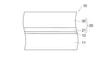
- Figure 2 shows a cross-sectional view of the decorated molded product 10. In Figure 2, the decorated molded product 10 is shown as being flat overall to facilitate understanding.
- the decorated molded product 10 includes a molded portion 11 and a decorative film 20.
- the decorative film 20 includes a bonding layer 21 and a decorative laminate 30.
- the decorative laminate 30 includes a first surface 30A and a second surface 30B.
- the decorative laminate 30 is sheet-shaped.
- the first surface 30A and the second surface 30B are the main surfaces of the decorative laminate 30.
- the second surface 30B is the surface opposite the first surface 30A.
- the bonding layer 21 is provided on the second surface 30B of the decorative laminate 30.
- the molded portion 11 is bonded to the decorative film 20 by the bonding layer 21.
- the bonding layer 21 may be omitted.
- the presence or absence of the bonding layer 21 can be appropriately selected depending on the molding method and the combination of the material of the molded portion 11 and the material of the decorative laminate 30.
- the molded portion 11 is positioned closer to the second surface 30B than to the first surface 30A of the decorative laminate 30.
- the first surface 30A of the decorative laminate 30 forms the surface of the decorative film 20 and the decorated molded product 10.
- the molded portion 11 is the main body of the exterior member.
- the molded portion 11 is the member to be decorated that is decorated by the decorative film 20.
- the molded portion 11 has the shape of at least a part of the exterior member of the moving body 1.
- the molded portion 11 has the shape of the roof of an automobile.
- the molded portion 11 is produced, for example, by molding a thermoplastic material.
- the molded portion 11 can be formed into a desired shape by molding.
- the material of the molded portion 11 is, for example, metal, glass, or resin.
- the resin is, for example, acrylic resin, polycarbonate resin, acrylonitrile-butadiene-styrene copolymer, polycarbonate resin, polypropylene resin, or fiber-reinforced plastic.
- the material of the molded portion 11 is, for example, resin.
- the material of the molded portion 11 is, for example, metal, glass, or resin.
- the material of the molded portion 11 is, for example, metal, glass, or resin.
- the decorated molded product 10 may further have an electrodeposition coating film 13 formed between the molded part 11 and the decorative film 20 as an undercoat coating, as shown in FIG. 2A.
- the decorative film 20 can replace the intermediate coating and top coating in conventional painting.
- the decorated molded product 10 may further have an anti-rust plating layer 15 for rust prevention formed on the surface of the molded part 11 as shown in FIG. 2B.
- the anti-rust plating layer 15 may be, for example, a zinc alloy plating film or an iron-nickel alloy plating film.
- the molded part 11 may be produced by applying the decorative film 20 to a molded metal plate.
- the molded part 11 may be produced by applying the decorative film 20 to a metal plate to form a laminated metal plate, and then molding the laminated metal plate.
- the bonding layer 21 bonds the decorative film 20 to the molded portion 11.
- the bonding layer 21 is provided on the surface of the decorative film 20.
- the bonding layer 21 may be a heat seal layer or an adhesive layer.
- the bonding layer 21 is preferably a heat seal layer.
- the bonding layer 21 is preferably an adhesive layer.
- the heat seal layer becomes adhesive when heated and bonds to other components.
- the heat seal layer has a thickness that provides appropriate adhesiveness and prevents the decorative film 20 from becoming too thick.
- the thickness of the heat seal layer may be 0.2 ⁇ m or more, or 20 ⁇ m or less.
- Materials for the heat seal layer include, for example, vinyl chloride-vinyl acetate copolymer, acrylic resin, polyester resin, and urethane resin.
- the adhesive layer exhibits adhesiveness and is bonded to other members by applying pressure.
- the adhesive layer exhibits appropriate adhesiveness and has a thickness that prevents the decorative film 20 from becoming too thick.
- the thickness of the adhesive layer may be 5 ⁇ m or more, or 300 ⁇ m or less.
- the material of the adhesive layer is, for example, an adhesive such as acrylic resin, urethane resin, silicone resin, rubber, etc.
- the adhesive layer Before bonding the decorative film 20 to the molding portion 11, the adhesive layer may be covered with a peelable separator (not shown) so that the decorative film 20 does not unintentionally adhere to other members.
- FIG. 3 shows a cross-sectional view of an example of the decorative film 20 before being bonded to the molded portion 11.
- the decorative film 20 includes a protective film 23.
- the protective film 23 is provided on the first surface 30A of the decorative laminate 30.
- the protective film 23 protects the first surface 30A of the decorative laminate 30. More specifically, the protective film 23 protects a surface layer 33 (described later) disposed on the first surface 30A of the decorative laminate 30.
- the protective film 23 is peelable from the decorative laminate 30.
- the protective film 23 is thin.
- the thickness of the protective film 23 may be 10 ⁇ m or more, or 100 ⁇ m or less.
- the material of the protective film 23 is, for example, polyethylene terephthalate (PET), polyester, or polyethylene.
- the decorative laminate 30 displays a design.
- the decorative molded product 10 including the decorative laminate 30 can display an excellent design.
- the mobile body 1 including the decorative molded product 10 exhibits an excellent appearance.
- the decorative laminate 30 may display a design such as a color or a geometric pattern.
- the decorative laminate 30 may display a design with a metallic or leather-like texture.
- the decorative laminate 30 may display a glossy or matte design.
- the image clarity of the design displayed by the decorative laminate 30 may be 60 or more, or 95 or less.
- the decorative laminate 30 displays a glossy design such as a metallic or matte design
- the image clarity is measured using a wavescan device (manufactured by BYK Japan, product name: Wavescan Dual AW-4840) and a method of measuring the measured value "distinctness of image (DOI)".
- a moving object 1 such as an automobile that includes the decorative laminate 30 can present a painted metallic or non-metallic (also called solid paint) design.
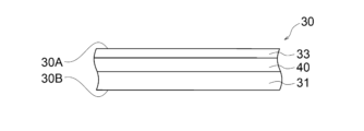
- FIG. 4 shows a cross-sectional view of a first example of a decorative laminate 30.
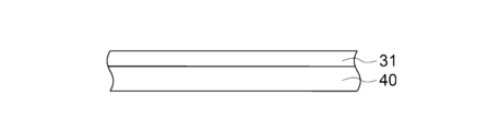
- the decorative laminate 30 includes, in this order from the first surface 30A to the second surface 30B, a surface layer 33, a base layer 31, and a design layer 40.
- FIG. 5 shows a cross-sectional view of a second example of a decorative laminate 30.
- the decorative laminate 30 includes, in this order from the first surface 30A to the second surface 30B, a surface layer 33, a design layer 40, and a base layer 31.
- the substrate layer 31 supports the other layers contained in the decorative laminate 30, particularly the design layer 40.
- the substrate layer 31 is in the form of a film.
- the substrate layer 31 is transparent.
- the thickness of the substrate layer 31 may be 50 ⁇ m or more, or 75 ⁇ m or more.
- the thickness of the substrate layer 31 may be 150 ⁇ m or less, or 125 ⁇ m or less.
- the material of the base layer 31 is, for example, a thermoplastic resin.
- the material of the base layer 31 is, for example, a (meth)acrylic resin, a polyolefin (for example, polyethylene, polypropylene, etc.), a polyester (for example, polyethylene naphthalate, polyethylene terephthalate, polybutylene terephthalate, etc.), a polyamide, a polycarbonate, a cellulose resin, a urethane resin (for example, thermoplastic polyurethane, etc.), a fluorine-based resin (for example, polyvinylidene fluoride (PVDF), a perfluoroalkoxyalkane (PFA), an ethylene-tetrafluoroethylene copolymer (ETFE), a perfluoroethylenepropene copolymer (FEP), a polytetrafluoroethylene (PTFE), etc.), an ABS resin, a polycarbonate resin, and a cellulose resin.
- the material of the base layer 31 is preferably a (meth)acrylic resin.
- the (meth)acrylic resin is, for example, a homopolymer or copolymer of a (meth)acrylic acid ester, and a copolymer of a (meth)acrylic acid ester and a comonomer.
- Examples of the (meth)acrylic acid ester include methyl (meth)acrylate, ethyl (meth)acrylate, butyl (meth)acrylate, 2-ethylhexyl (meth)acrylate, hydroxyethyl (meth)acrylate, hydroxypropyl (meth)acrylate, dimethylaminoethyl (meth)acrylate, and glycidyl (meth)acrylate.
- Examples of the comonomer include vinyl acetate, (meth)acrylonitrile, (meth)acrylamide, styrene, (meth)acrylic acid, itaconic acid, and maleic anhydride.
- the (meth)acrylic resin may be fluorine-modified.
- the material of the base layer 31 may be a single layer of a mixture of two or more of the above-mentioned resins, or may be composed of multiple layers.
- the base layer 31 composed of multiple layers can be produced, for example, by
- the substrate layer 31 may contain a colorant.
- the colorant contained in the substrate layer 31 may be a chromatic color or an achromatic color.
- the substrate layer 31 can be colored to a desired color by the colorant.
- the substrate layer 31 is colored and transparent.
- the color exhibited by the substrate layer 31 may be the same as the color exhibited by the backer layer 37 in the decorative laminate 30 of the third example described below.
- the colorant may have the same composition as the colorant contained in the glittering layer 41 and colored layer 43 of the design layer 40 described below.
- transparent means that the material has a degree of transparency that allows one to see through the material from one side to the other, and for example, has a visible light transmittance of 30% or more, and more preferably 70% or more.
- colored transparent means that the transmittance of light in a specific wavelength range is intentionally low, but the transmittance of visible light as a whole is high, making it transparent.
- visible light transmittance is specified as the average value of the total light transmittance at each wavelength when measured in 1 nm increments in the measurement wavelength range of 380 nm to 780 nm using a spectrophotometer (Shimadzu Corporation's "UV-3600i Plus", compliant with JIS K0115).
- the angle of incidence when measuring visible light transmittance is set to 0° unless a specific transmission direction is specified.
- the angle of incidence is the angle between the normal to the incident surface and the traveling direction of the incident light, and is less than 90°.
- the surface layer 33 protects the other layers of the decorative laminate 30.
- the surface layer 33 has various functions such as abrasion resistance, weather resistance, and chemical resistance.
- the surface layer 33 has, for example, abrasion resistance, weather resistance, chemical resistance, and extensibility required for molding, which are required for exterior parts of automobiles, etc.
- the surface layer 33 is arranged closer to the first surface 30A than the second surface 30B with respect to the base layer 31.
- the surface layer 33 forms the first surface 30A of the decorative laminate 30.
- the surface layer 33 forms the surface of the decorated molded product 10.
- the surface layer 33 is in the form of a thin film.
- the surface layer 33 is transparent.
- the thickness of the surface layer 33 may be 1 ⁇ m or more, or may be 2 ⁇ m or more.
- the thickness of the surface layer 33 may be 20 ⁇ m or less, or may be 10 ⁇ m or less.
- the material of the surface layer 33 is a cured product of a curable resin composition. More specifically, the material of the surface layer 33 is a cured product of an ionizing radiation curable resin composition.
- the surface layer 33 can have any configuration.
- curable components contained in the curable resin composition examples include thermosetting components and active energy ray curable components. From the viewpoints of weather resistance, abrasion resistance, and chemical resistance, active energy ray curable components are preferred.
- thermosetting components are, for example, thermosetting resins such as epoxy resins, melamine resins, guanamine resins, urea resins, unsaturated polyesters, thermosetting urethane resins, thermosetting (meth)acrylic resins, and aminoalkyd resins.
- thermosetting resins such as epoxy resins, melamine resins, guanamine resins, urea resins, unsaturated polyesters, thermosetting urethane resins, thermosetting (meth)acrylic resins, and aminoalkyd resins.
- the active energy ray curable component is a component that cures when irradiated with active energy rays.
- active energy rays include electromagnetic waves such as ultraviolet rays (UV), X-rays, and gamma rays; and charged particle beams such as electron beams (EB), alpha rays, and ion beams.
- the active energy ray curable component is, for example, a compound having at least one functional group selected from a vinyl group, an allyl group, and a (meth)acryloyl group.
- the active energy ray curable component is, for example, an oligomer or polymer such as urethane (meth)acrylate, epoxy (meth)acrylate, polyester (meth)acrylate, and polyether (meth)acrylate; a polyfunctional (meth)acrylate monomer such as trimethylolpropane tri(meth)acrylate, pentaerythritol tri(meth)acrylate, pentaerythritol tetra(meth)acrylate, dipentaerythritol tri(meth)acrylate, dipentaerythritol tetra(meth)acrylate, dipentaerythritol penta(meth)acrylate, dipentaerythritol hexa(meth)acrylate, and tri
- the curable resin composition may contain a photopolymerization initiator in addition to the active energy ray-curable component.
- the surface layer 33 may contain a weather resistance improver. This can improve the weather resistance of the surface layer.
- the weather resistance improver is, for example, an ultraviolet absorber, an antioxidant, or a hindered amine light stabilizer.
- the content of the weather resistance improver in the surface layer 33 may be 0.1 mass% or more.
- the content of the weather resistance improver in the surface layer 33 may be 10 mass% or less, or 5 mass% or less.
- the surface layer 33 is protected by the protective film 23.
- the curable resin composition that is the material of the surface layer 33 may not be cured, or may be in a semi-cured state.
- the protective film 23 may be peeled off from the surface layer 33 before the curable resin composition cures, or the protective film 23 may be peeled off from the surface layer 33 after the curable resin composition cures.
- the design layer 40 forms the design displayed by the decorative laminate 30.
- the design layer 40 is supported by the base layer 31.
- the design layer 40 includes at least one of a photoluminescent layer 41 and a colored layer 43.
- the design layer 40 may include a photoluminescent layer 41, a second photoluminescent layer 42, a colored layer 43, and a transparent layer 45.
- FIG. 6 shows a cross-sectional view of the design layer 40 of the first example.
- the design layer 40 includes a photoluminescent layer 41.
- the design layer 40 consists only of the photoluminescent layer 41.
- the glittering layer 41 reflects light so as to exhibit luster.
- the SCE L * value of the color exhibited by the glittering layer 41 may be 10 or more, 25 or more, 35 or more, 60 or less, 50 or less, or 48 or less.
- the SCI L * value of the color exhibited by the glittering layer 41 may be 20 or more, 30 or more, 40 or more, 90 or less, 80 or less, or 65 or less.
- the SCE L * value and SCI L * value in the L * a * b * color system of the color exhibited by the glittering layer 41 can be measured using a spectrophotometer (Konica Minolta's "CM-700d") under conditions of a measurement diameter of ⁇ 8 mm and a viewing angle of 10 degrees as follows.
- a black plate with an L * value of 29.9 is placed on the back surface of the member to be measured.
- Light from a D65 light source is irradiated onto the surface opposite to the surface on which the black plate is placed.
- the SCE L * value of the member to be measured is determined by excluding specular reflection from the light reflected by total reflection on the member to be measured.
- the SCI L * value of the member to be measured is determined from the light reflected by total reflection on the member to be measured.
- the photoluminescent layer 41 includes a binder resin 41a and a photoluminescent material 41b.
- the photoluminescent material 41b is encapsulated in the binder resin 41a.
- the content of the photoluminescent material 41b in the photoluminescent layer 41 may be 3 mass% or more, or 75 mass% or less.
- the visible light transmittance of the photoluminescent layer 41 may be 0.5% or more, or 1% or more.
- the visible light transmittance of the photoluminescent layer 41 may be 95% or less, or 90% or less.
- the thickness of the photoluminescent layer 41 may be 2 ⁇ m or more, 3 ⁇ m or more, or 100 ⁇ m or less.
- the binder resin 41a is, for example, a resin such as urethane resin, acrylic polyol resin, acrylic resin, ester resin, amide resin, butyral resin, styrene resin, urethane-acrylic copolymer, vinyl chloride-vinyl acetate copolymer resin, vinyl chloride-vinyl acetate-acrylic copolymer resin, chlorinated propylene resin, nitrocellulose resin, or cellulose acetate resin.
- a resin such as urethane resin, acrylic polyol resin, acrylic resin, ester resin, amide resin, butyral resin, styrene resin, urethane-acrylic copolymer, vinyl chloride-vinyl acetate copolymer resin, vinyl chloride-vinyl acetate-acrylic copolymer resin, chlorinated propylene resin, nitrocellulose resin, or cellulose acetate resin.
- the glittering material 41b reflects light.
- the glittering material 41b is, for example, aluminum flakes, mica, or pearl pigment.
- the glittering material 41b is, for example, oriented in a direction along the surface on which the glittering layer 41 is formed.
- the average particle size of the glittering material 41b is within a range in which light is appropriately reflected by the glittering layer 41. If the average particle size of the glittering material 41b is too small, the glittering layer 41 does not reflect light sufficiently. If the average particle size of the glittering material 41b is too large, the glittering material 41b does not orient along the surface on which the glittering layer 41 is formed, and light is diffusely reflected by the glittering layer 41, making it difficult for the glittering layer 41 to exhibit luster.
- the thickness of the glittering material 41b may be 20 nm or more.
- the thickness of the glittering material 41b may be 1 ⁇ m or less, 700 nm or less, 500 nm or less, or 300 nm or less.
- the average particle size of the lustrous material 41b may be 5 ⁇ m or more, 10 ⁇ m or more, 25 ⁇ m or less, or 15 ⁇ m or less.
- the average particle size of the photoluminescent material 41b is determined as follows.
- the photoluminescent layer 41 is magnified under a microscope to observe each of the photoluminescent materials 41b.
- the particle size of each of the observed photoluminescent materials 41b is measured. If the photoluminescent material 41b has a minor axis diameter and a major axis diameter, the average of these diameters is taken as the particle size of the photoluminescent material 41b. If the photoluminescent material 41b is aggregated, the particle size of the photoluminescent material 41b is taken as the diameter of the inscribed circle in the aggregated portion.
- the particle sizes of 100 photoluminescent materials 41b are measured, and the average is taken as the average particle size of the photoluminescent material 41b in the photoluminescent layer 41.
- the planar arrangement of the photoluminescent material 41b in the photoluminescent layer 41 may change before and after the stretching.
- the photoluminescent material 41b in the photoluminescent layer 41 may be arranged so as to overlap in the stacking direction in a cross-sectional view.
- a certain photoluminescent material 41b in the photoluminescent layer 41 may be arranged so as to at least partially overlap with another photoluminescent material 41b located above and below it in the stacking direction.
- the photoluminescent material 41b in the photoluminescent layer 41 may overlap one or more other photoluminescent materials 41b in the stacking direction, may overlap two or more other photoluminescent materials 41b in the stacking direction, or may overlap three or more other photoluminescent materials 41b in the stacking direction.
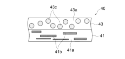
- FIG. 7 shows a cross-sectional view of the design layer 40 of the second example.
- the design layer 40 includes a photoluminescent layer 41.
- the design layer 40 consists only of the photoluminescent layer 41.
- the photoluminescent layer 41 reflects light to give it a glossy appearance and displays color.
- the photoluminescent layer 41 includes a binder resin 41a, a photoluminescent material 41b, and a colorant 41c.
- the photoluminescent material 41b and the colorant 41c are encapsulated in the binder resin 41a.
- the colorant 41c colors the photoluminescent layer 41 to a desired color.
- the color of the colorant 41c may be a chromatic color or an achromatic color.
- the colorant 41c is a dye or a pigment.
- the colorant 41c may be a combination of a dye and a pigment.
- the colorant 41c is a material different from the photoluminescent material 41b. For example, aluminum flakes, mica, and pearl pigments are not used as the colorant 41c. Considering weather resistance, it is preferable that the colorant 41c is a pigment.
- the pigment may be a colored pigment or a fluorescent pigment.
- the colored pigment may be an organic pigment such as a quinacridone pigment such as quinacridone red, an azo pigment such as pigment red, a phthalocyanine pigment such as phthalocyanine blue or phthalocyanine green, or a perylene pigment such as perylene red, or an inorganic pigment such as titanium oxide or carbon black.
- a quinacridone pigment such as quinacridone red
- an azo pigment such as pigment red
- a phthalocyanine pigment such as phthalocyanine blue or phthalocyanine green
- a perylene pigment such as perylene red
- an inorganic pigment such as titanium oxide or carbon black.
- FIG. 8 shows a cross-sectional view of the design layer 40 of the third example.
- the design layer 40 includes a photoluminescent layer 41 and a colored layer 43.
- the photoluminescent layer 41 may be disposed closer to the first surface 30A of the decorative laminate 30 than the colored layer 43, or the colored layer 43 may be disposed closer to the first surface 30A of the decorative laminate 30 than the photoluminescent layer 41.
- the photoluminescent layer 41 reflects light to give it a glossy appearance, similar to the photoluminescent layer 41 in the design layer 40 of the first example.
- the photoluminescent layer 41 includes a binder resin 41a and a photoluminescent material 41b.
- the colored layer 43 displays a color.
- the colored layer 43 includes a binder resin 43a and a colorant 43c.
- the colorant 43c is encapsulated in the binder resin 43a.
- the binder resin 43a of the colored layer 43 may have the same configuration as the binder resin 41a of the glossy layer 41 in the design layer 40 of the first example.
- the color of the colorant 43c may be a chromatic color or an achromatic color.
- the colorant 43c of the colored layer 43 may have the same configuration as the colorant 41c of the glossy layer 41 in the design layer 40 of the second example.
- the visible light transmittance of the colored layer 43 may be 5% or more, or 90% or less.
- the thickness of the colored layer 43 may be 2 ⁇ m or more, or 50 ⁇ m or less.
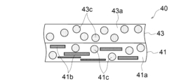
- the design layer 40 includes a glittering layer 41 and a coloring layer 43.
- the glittering layer 41 may be disposed closer to the first surface 30A of the decorative laminate 30 than the coloring layer 43, or the coloring layer 43 may be disposed closer to the first surface 30A of the decorative laminate 30 than the glittering layer 41.
- the glittering layer 41 reflects light to give a glossy appearance and displays a color, similar to the glittering layer 41 in the design layer 40 of the second example.
- the glittering layer 41 includes a binder resin 41a, a glittering material 41b, and a coloring agent 41c.
- the coloring layer 43 displays a color, similar to the coloring layer 43 in the design layer 40 of the third example.
- the coloring layer 43 includes a binder resin 43a and a coloring agent 43c.
- the design layer 40 includes a glossy layer 41, a second glossy layer 42, and a colored layer 43.
- the second glossy layer 42 is superimposed on the glossy layer 41.
- the second glossy layer 42 is disposed closer to the first surface 30A than to the second surface 30B of the decorative laminate 30 with respect to the glossy layer 41.
- the colored layer 43, the second glossy layer 42, and the glossy layer 41 are disposed in this order from the first surface 30A toward the second surface 30B.
- the order of the colored layer 43, the second glossy layer 42, and the glossy layer 41 in the design layer 40 is not limited to the example shown.
- the second photoluminescent layer 42, the colored layer 43, and the photoluminescent layer 41 may be arranged in this order from the first surface 30A toward the second surface 30B.
- the photoluminescent layer 41 reflects light to give a glossy appearance, similar to the photoluminescent layer 41 in the design layer 40 of the first example.
- the photoluminescent layer 41 contains a binder resin 41a and a photoluminescent material 41b.
- the colored layer 43 displays a color, similar to the colored layer 43 in the design layer 40 of the third example.
- the colored layer 43 contains a binder resin 43a and a colorant 43c.
- the second photoluminescent layer 42 may have a similar configuration to the photoluminescent layer 41.
- the second photoluminescent layer 42 reflects light to give it a glossy appearance.
- the second photoluminescent layer 42 includes a binder resin 42a and a photoluminescent material 42b.
- the photoluminescent material 42b is encapsulated in the binder resin 42a.
- the binder resin 42a of the second photoluminescent layer 42 may have a similar configuration to the binder resin 41a of the photoluminescent layer 41 in the design layer 40 of the first example.
- the photoluminescent material 42b of the second photoluminescent layer 42 may have a similar configuration to the photoluminescent material 41b of the photoluminescent layer 41 in the design layer 40 of the first example.
- the content of the photoluminescent material 41b contained in the photoluminescent layer 41 is different from the content of the photoluminescent material 42b contained in the second photoluminescent layer 42.
- the content of the glittering material 41b contained in the glittering layer 41 is higher than the content of the glittering material 42b contained in the second glittering layer 42.
- the content of the glittering material means the ratio of the area occupied by the glittering material per unit area in the cross section of the layer containing the glittering material.
- the second glittering layer 42 may display a color.
- the second glittering layer 42 may contain a colorant.
- the colorant contained in the second glittering layer 42 may have a similar structure to the colorant 41c of the glittering layer 41 in the design layer 40 of the second example.
- the content of the colorant in the second glittering layer 42 may be the same as or different from the content of the colorant 41c in the glittering layer 41.
- the content of the colorant in the second glittering layer 42 may be lower or higher than the content of the colorant 41c in the glittering layer 41.
- the content of the photoluminescent material in the lower layer may be lower, the same, or higher than the content of the photoluminescent material in the upper layer.
- the content of the photoluminescent material in the upper layer may be 5% or more of the content of the photoluminescent material in the lower layer, or may be 1000% or less.
- the ratio of the content of the photoluminescent material in the upper layer to the content of the photoluminescent material in the lower layer is set so as to reduce the change in the light reflectance in the laminated layers containing the photoluminescent material when the decorative laminate 30 is molded and stretched.
- the content of the colorant in the lower layer may be lower, the same, or higher than the content of the colorant in the upper layer.
- the upper layer means the layer that is closer to the first surface 30A of the decorative laminate 30 among the laminated layers.
- the lower layer means the layer that is closer to the second surface 30B of the decorative laminate 30 among the laminated layers.
- the content of the luster material in a layer containing the laminated luster material is compared based on the ratio of the area occupied by the luster material per unit area in the cross section of the layer.
- the content of photoluminescent material on the side closer to the second surface 30B may be lower, the same as, or higher than the content of photoluminescent material on the side closer to the first surface 30A.
- the photoluminescent layer 41 in each example contains a colorant
- the content of colorant on the side closer to the second surface 30B may be lower, the same as, or higher than the content of colorant on the side closer to the first surface 30A.
- the glossy layer 41 and the second glossy layer 42 may be overlapped so as to be in direct contact with each other. In this case, the glossy layer 41 and the second glossy layer 42 are easily adhered to each other by the respective binder resins.
- FIG. 11 shows a cross-sectional view of the design layer 40 of the sixth example.
- the design layer 40 includes a glossy layer 41, a colored layer 43, and a transparent layer 45.
- the transparent layer 45 is disposed between the glossy layer 41 and the colored layer 43.
- the glossy layer 41 reflects light to give a glossy appearance, similar to the glossy layer 41 in the design layer 40 of the first example.
- the glossy layer 41 includes a binder resin 41a and a glossy material 41b.
- the colored layer 43 displays a color, similar to the colored layer 43 in the design layer 40 of the third example.
- the colored layer 43 includes a binder resin 43a and a colorant 43c.
- the transparent layer 45 separates the glossy layer 41 and the colored layer 43.
- the transparent layer 45 contains a binder resin 45a.
- the binder resin 45a of the transparent layer 45 may have a similar configuration to the binder resin 41a of the glossy layer 41 in the design layer 40 of the first example.
- the transparent layer 45 has a thickness corresponding to the distance between the glossy layer 41 and the colored layer 43.
- the thickness of the transparent layer 45 may be 10 ⁇ m or more, or may be 25 ⁇ m or more.
- the thickness of the transparent layer 45 may be 300 ⁇ m or less, or may be 200 ⁇ m or less.
- the design layer 40 includes a glossy layer 41, a second glossy layer 42, a colored layer 43, and a transparent layer 45.
- the second glossy layer 42 is superimposed on the glossy layer 41.
- the second glossy layer 42 is disposed closer to the first surface 30A than to the second surface 30B of the decorative laminate 30 with respect to the glossy layer 41.
- the colored layer 43, the transparent layer 45, the second glossy layer 42, and the glossy layer 41 are disposed in this order from the first surface 30A toward the second surface 30B.
- the order of the colored layer 43, the transparent layer 45, the second glossy layer 42, and the glossy layer 41 in the design layer 40 is not limited to the example shown in the figure.
- the second glossy layer 42, the transparent layer 45, the colored layer 43, and the glossy layer 41 may be arranged in this order from the first surface 30A to the second surface 30B.
- the glossy layer 41 reflects light to give a glossy appearance, similar to the glossy layer 41 in the design layer 40 of the first example.
- the glossy layer 41 includes a binder resin 41a and a glossy material 41b.
- the second glossy layer 42 reflects light to give a glossy appearance, similar to the second glossy layer 42 in the design layer 40 of the fifth example.
- the second glossy layer 42 includes a binder resin 42a and a glossy material 42b.
- the colored layer 43 displays a color, similar to the colored layer 43 in the design layer 40 of the third example.
- the colored layer 43 includes a binder resin 43a and a colorant 43c.
- the transparent layer 45 separates the glossy layer 41 and the colored layer 43, similar to the transparent layer 45 in the design layer 40 of the sixth example.
- the transparent layer 45 contains a binder resin 45a.
- FIG. 13 shows a cross-sectional view of the design layer 40 of the eighth example.
- the design layer 40 includes a colored layer 43.
- the design layer 40 consists only of the colored layer 43.
- the colored layer 43 displays color, similar to the colored layer 43 in the design layer 40 of the third example.
- the colored layer 43 includes a binder resin 43a and a colorant 43c.
- the design layer 40 in the eighth example forms a design in the color of, for example, piano black.
- the design layer 40 is not limited to the above-mentioned examples.
- the design layer 40 may be, for example, a combination of the design layers 40 of the above-mentioned examples.
- the design layer 40 may include other layers for forming the design.
- the design layer 40 may further include a third photoluminescent layer that includes a photoluminescent material encapsulated in a binder resin.
- FIG. 14 shows a cross-sectional view of a third example of the decorative laminate 30.
- the decorative laminate 30 includes, from the first surface 30A to the second surface 30B, a surface layer 33, a base layer 31, a design layer 40, an adhesive layer 38, and a backer layer 37, in this order. Not limited to the example shown, the backer layer 37 and/or the adhesive layer 38 may be omitted.
- the backer layer 37 maintains the shape of the decorative laminate 30 when the decorative film 20 having the decorative laminate 30 is formed.
- the backer layer 37 is disposed closer to the second surface 30B of the design layer 40 than to the first surface 30A. In the illustrated example, the backer layer 37 forms the second surface 30B of the decorative laminate 30.
- the backer layer 37 may cushion the impact on the other layers of the decorative laminate 30 and the molded portion 11 when the decorative laminate 30 is impacted from the outside by flying stones or the like, similar to the buffer layer 39 described later.
- the backer layer 37 is in a sheet form.
- the thickness of the backer layer 37 may be 50 ⁇ m or more, or 500 ⁇ m or less.
- the material of the backer layer 37 is, for example, a thermoplastic resin. Specifically, the material of the backer layer 37 is, for example, an acrylonitrile-butadiene-styrene copolymer, polypropylene, polycarbonate, polymethyl methacrylate, or polyvinyl chlor
- the backer layer 37 may be colored.
- the backer layer 37 may contain a colorant.
- the color of the colorant contained in the backer layer 37 may be a chromatic color or an achromatic color.
- the backer layer 37 can be colored to a desired color by the colorant.
- the color of the backer layer 37 is preferably set to match the color exhibited by the design layer 40.
- the colorant contained in the backer layer 37 may have the same composition as the colorant contained in the glittering layer 41 and colored layer 43 of the design layer 40 described above.
- the color presented by the backer layer 37 may be a similar color to the color presented by the design layer 40.
- the color presented by the backer layer 37 may be a similar color to the color presented by the design layer 40. Similar colors refer to colors with the same hue, and include colors with different lightness and saturation. Similar colors refer to colors that are within an angle of 30 degrees from the center of the hue wheel in a continuous hue wheel, and include colors with different lightness and saturation. For example, if the color presented by the design layer 40 is red, a brown backer layer 37 can be used.
- the difference between the L * value L * 1 of the color presented by the backer layer 37 and the L * value L * 2 of the color presented by the design layer 40 may be 10 or less, 8 or less, 6 or less, or 4 or less.
- the value of ((a * 1 - a * 2 ) 2 + (b * 1 - b * 2 ) 2 ) 1/2 may be 20 or less, 17 or less, 15 or less, 13 or less, or 11 or less.
- the L * , a * , and b* values in the L * a * b * color system of the color exhibited by the backer layer 37 and the color exhibited by the design layer 40 can be measured using a spectrophotometer (Konica Minolta's "CM-700d") under the conditions of a measurement diameter of ⁇ 8 mm and a viewing angle of 10 degrees as follows.
- a black plate with an L * value of 29.9 is placed on the back of the member to be measured.
- Light from a D65 light source is irradiated onto the surface opposite to the surface on which the black plate is placed.
- the L * , a * , and b * values of the member to be measured are determined from the light reflected by total reflection at the member to be measured.
- the adhesive layer 38 bonds the backer layer 37 to the other layers of the decorative laminate 30.
- the adhesive layer 38 bonds the backer layer 37 to the design layer 40.
- the adhesive layer 38 is disposed between the backer layer 37 and the design layer 40.
- the adhesive layer 38 like the buffer layer 39 described later, may cushion the impact on the other layers of the decorative laminate 30 and the molded portion 11 when the decorative laminate 30 is impacted from the outside by a flying stone or the like.
- the adhesive layer 38 is thin-film shaped.
- the thickness of the adhesive layer 38 may be 1 ⁇ m or more, or 20 ⁇ m or less.
- the visible light transmittance of the adhesive layer 38 may be 0% or more, 50% or more, 100% or less, or 20% or less.
- the material of the adhesive layer 38 is, for example, a thermoplastic resin such as an acrylic resin, a vinyl chloride-vinyl acetate copolymer, a chlorinated polyolefin resin, or an acid-modified polyolefin resin, a two-component curing type urethane resin, or a curable resin such as an epoxy resin.
- a thermoplastic resin such as an acrylic resin, a vinyl chloride-vinyl acetate copolymer, a chlorinated polyolefin resin, or an acid-modified polyolefin resin, a two-component curing type urethane resin, or a curable resin such as an epoxy resin.
- the adhesive layer 38 may be colored.
- the adhesive layer 38 may contain a colorant.
- the color of the colorant contained in the adhesive layer 38 may be chromatic or achromatic.
- the adhesive layer 38 can be colored to a desired color by the colorant.
- the color of the adhesive layer 38 is preferably set to match the color of the design layer 40.
- the color setting may be the same as the color of the backer layer 37 in the decorative laminate 30 of the third example described above.
- the colorant contained in the adhesive layer 38 may have the same configuration as the colorant contained in the glittering layer 41 and colored layer 43 of the design layer 40 described above.
- FIG. 15 shows a cross-sectional view of a fourth example of the decorative laminate 30.
- the decorative laminate 30 includes, from the first surface 30A toward the second surface 30B, a surface layer 33, a base layer 31, a design layer 40, an adhesive layer 38, a concealing layer 35, and a backer layer 37, in this order.
- the backer layer 37 and/or the adhesive layer 38 may be omitted.
- the concealing layer 35 conceals other components provided on the second surface 30B of the decorative laminate 30, such as the molded portion 11, so that they are difficult to observe from the first surface 30A of the decorative laminate 30.
- the concealing layer 35 is disposed closer to the second surface 30B of the design layer 40 than the first surface 30A.
- the concealing layer 35 is disposed between the adhesive layer 38 and the backer layer 37.
- the concealing layer 35 may be disposed between the design layer 40 and the adhesive layer 38.
- the concealing layer 35 is a thin film.
- the thickness of the concealing layer 35 may be 2 ⁇ m or more, 10 ⁇ m or more, 100 ⁇ m or less, or 20 ⁇ m or less.
- the visible light transmittance of the concealing layer 35 is sufficiently low. Specifically, the visible light transmittance of the concealing layer 35 may be 20% or less.
- the concealing layer 35 contains a colorant.
- the colorant contained in the concealing layer 35 may be a chromatic color or an achromatic color.
- the colorant is used to color the concealing layer 35 in a desired color.
- the color of the concealing layer 35 is preferably set to match the color of the design layer 40.
- the color may be set in the same way as the color of the backer layer 37 in the decorative laminate 30 of the third example described above.
- the colorant contained in the concealing layer 35 may have the same configuration as the colorant contained in the glittering layer 41 and colored layer 43 of the design layer 40 described above.
- FIG. 16 shows a cross-sectional view of a fifth example of the decorative laminate 30.
- the decorative laminate 30 includes, from the first surface 30A to the second surface 30B, a surface layer 33, a base layer 31, a design layer 40, a reflective layer 36, an adhesive layer 38, and a backer layer 37, in this order.
- the backer layer 37 and/or the adhesive layer 38 may be omitted.
- the reflective layer 36 reflects light so that other components provided on the second surface 30B of the decorative laminate 30, such as the molded portion 11, cannot be observed from the first surface 30A of the decorative laminate 30, and so that the design formed by the design layer 40 can be observed more clearly.
- the reflective layer 36 reflects light that is not reflected by the glossy layer 41 of the design layer 40 and is transmitted through the design layer 40.
- the reflective layer 36 is disposed closer to the second surface 30B of the design layer 40 than the first surface 30A.
- the reflective layer 36 is disposed between the design layer 40 and the adhesive layer 38.
- the reflective layer 36 may be disposed between the adhesive layer 38 and the backer layer 37.
- the reflective layer 36 is in the form of a thin film.
- the thickness of the reflective layer 36 may be 30 nm or more, 2 ⁇ m or more, 20 ⁇ m or less, or 100 nm or less.
- the visible light transmittance of the reflective layer 36 may be 0% or more, or 20% or less.
- the material of the reflective layer 36 is, for example, a vapor deposition film of aluminum, indium or tin, or achromatic or silver ink.
- FIG. 17 shows a cross-sectional view of a sixth example of the decorative laminate 30.
- the decorative laminate 30 includes, from the first surface 30A toward the second surface 30B, a surface layer 33, a buffer layer 39, a base layer 31, a design layer 40, an adhesive layer 38, and a backer layer 37, in this order.
- the backer layer 37 and/or the adhesive layer 38 may be omitted.
- the buffer layer 39 cushions the impact on the other layers of the decorative laminate 30 and the molded portion 11 when the decorative laminate 30 receives an external impact from a flying stone or the like.
- the buffer layer 39 is, for example, a layer that contains a plasticizer and has chipping resistance.
- the plasticizer are phthalic acid-based plasticizers, fatty acid-based plasticizers, phosphoric acid-based plasticizers, polyester-based plasticizers, polyethylene-based plasticizers, and epoxy-based plasticizers.
- phthalic acid-based plasticizers examples include phthalate diesters such as dioctyl phthalate, di-2-ethylhexyl phthalate, dihexyl phthalate, dibutyl phthalate, diheptyl phthalate, diisodecyl phthalate, and diisononyl phthalate.
- fatty acid plasticizers include aliphatic polybasic acid diesters such as dioctyl adipate, dioctyl azelate, and dioctyl verlate; and citric acid triesters such as tributyl acetyl citrate, trioctyl acetyl citrate, and tributyl citrate.
- the buffer layer 39 is a layer that contains an elastomer and has chipping resistance.
- the elastomer include styrene-based elastomers, polyester-based elastomers, urethane-based elastomers, olefin-based elastomers, and polyamide-based elastomers.
- the buffer layer 39 is disposed closer to the second surface 30B than to the first surface 30A with respect to the surface layer 33.
- the buffer layer 39 is disposed between the surface layer 33 and the base material layer 31.
- the buffer layer 39 may be disposed between the base material layer 31 and the design layer 40, between the design layer 40 and the adhesive layer 38, or between the adhesive layer 38 and the backer layer 37.
- the backer layer 37 may have the function of the buffer layer 39. In other words, the backer layer 37 and the buffer layer 39 may be the same layer.
- the buffer layer 39 is a thin film.
- the thickness of the buffer layer 39 may be 10 ⁇ m or more, or 500 ⁇ m or less.
- the buffer layer 39 may include multiple layers.
- the material of the buffer layer 39 is, for example, a resin containing a polyester plasticizer such as an adipic acid polyester or a phthalic acid polyester, a vinyl chloride-vinyl acetate copolymer, a polyurethane resin, a polyester resin, an epoxy resin, an acrylic resin, or a polyolefin resin.
- the amount of plasticizer contained in the buffer layer 39 may be 1 part by mass or more, or may be less than 40 parts by mass.
- the decorative laminate 30 including the buffer layer 39 is unlikely to impair the design to be displayed. Even if a stone chip test is performed on the decorative laminate 30 including the buffer layer 39, it can be confirmed that the design to be displayed is hardly impaired by visual inspection. Even if a stone chip test is performed on the decorative laminate 30 including the buffer layer 39, the buffer layer 39 cushions the impact, so that peeling and cracking of the layers constituting the decorative film 20 can be suppressed. Even if a stone chip test is performed on the decorative laminate 30 including the buffer layer 39, the buffer layer 39 cushions the impact, so that peeling of the decorative film 20 including the decorative laminate 30 from the molded part 11 can be suppressed.
- the stone chip test is performed using a Gravelo tester JA400 (manufactured by Suga Testing Machine Co., Ltd.) under the following conditions. ⁇ Test conditions> Shot material: JIS A5001 (road crushed stone) No. 7 shot material quantity: 50g Distance: 35 cm Shot pressure: 0.39MPa Shot angle: 90° Test temperature: -20°C
- the buffer layer 39 may contain a colorant.
- the color of the buffer layer 39 may be the same color as the color of the design layer 40, or may be a similar color.
- the decorative laminate 30 is not limited to the above-mentioned examples.
- the decorative laminate 30 may be, for example, a combination of the decorative laminates 30 of the above-mentioned examples.
- the decorative laminate 30 may include, in this order from the first surface 30A to the second surface 30B, a surface layer 33, a design layer 40, a base layer 31, a buffer layer 39, a concealing layer 35, a reflective layer 36, a colored adhesive layer 38, and a colored backer layer 37.
- the decorative laminate 30 includes the concealing layer 35 and the reflective layer 36, the reflective layer 36 is disposed closer to the second surface 30B than the first surface 30A with respect to the concealing layer 35.
- the decorative laminate 30 may include other layers that exhibit desired functions.
- the layers capable of cushioning the impact on the other layers of the decorative laminate 30 and the molded portion 11 when impacted from the outside by flying stones or the like are sufficiently thick to adequately cushion the impact from the outside.
- the ratio of the sum of the thicknesses of the adhesive layer 38, backer layer 37, and buffer layer 39 to the sum of the thicknesses of the surface layer 33, base layer 31, and design layer 40 may be 0.14 or more, or may be 19 or less.
- the ratio of the sum of the thicknesses of the adhesive layer 38 and backer layer 37 to the sum of the thicknesses of the surface layer 33, base layer 31, and design layer 40 may be 0.12 or more, or may be 9.6 or less.
- the ratio of the total thickness of the adhesive layer 38 and the buffer layer 39 to the total thickness of the surface layer 33, the base layer 31, and the design layer 40 may be 0.020 or more, or 9.6 or less.
- the thickness of the decorative laminate 30 may be 60 ⁇ m or more, 100 ⁇ m or more, 1 mm or less, or 500 ⁇ m or less.
- the decorative laminate 30 can be wound into a roll.
- the decorative laminate 30 can be easily handled.
- the time required to heat the decorative laminate 30 to a temperature at which it can be molded is shortened when molding the decorative laminate 30. This makes it easier to manufacture the decorated molded product 10.
- the decorative laminate 30 is sufficiently thin, the cost of the decorative laminate 30 itself can be reduced.
- the decorative laminate 30 can maintain an appropriate shape even when molded. Because the decorative laminate 30 is sufficiently thick, the decorative laminate 30 is less likely to be damaged by heat when it is molded, even if the temperature of the decorative laminate 30 is raised to a temperature at which the decorative laminate 30 can be molded.
- the method for manufacturing the decorative laminate 30 includes a step of printing or applying the design layer 40 to the base layer 31, and a step of forming the surface layer 33.
- the method for manufacturing the decorative film 20 includes a step of providing a bonding layer 21 on the decorative laminate 30.
- the method for manufacturing the decorated molded product 10 includes a step of vacuum forming the decorative film 20 or the decorative laminate 30, and a step of forming a molded portion 11 on the decorative film 20 or the decorative laminate 30.
- a design layer 40 is provided on the base layer 31.
- Each layer contained in the design layer 40 is printed or applied to the base layer 31 in order.
- a process of providing the design layer 40 of the example shown in Figure 8 on the base layer 31 by printing will be described.
- a colored layer 43 containing a binder resin 43a and a colorant 43c is printed on the base layer 31.
- a photoluminescent layer 41 containing a binder resin 41a and a photoluminescent material 41b is printed on the colored layer 43.
- the colored layer 43 and the photoluminescent layer 41 are provided by any printing method such as offset printing, inkjet printing, gravure printing, screen printing, etc.
- the printing method may be selected appropriately depending on the colorant and photoluminescent material contained in the colored layer 43 and the photoluminescent layer 41. Because the thickness of the provided photoluminescent layer 41 is sufficiently thin and the average particle size of the photoluminescent material 41b is sufficiently small, the photoluminescent material 41b contained in the photoluminescent layer 41 is oriented along the surface on which the photoluminescent layer 41 is formed. By forming the photoluminescent layer 41 by printing, it is easier to orient the photoluminescent material 41b in a direction along the main surface compared to painting.
- a process of providing the design layer 40 of the example shown in FIG. 8 on the base layer 31 by coating will be described.
- a colored layer 43 containing a binder resin 43a and a colorant 43c is coated on the base layer 31.
- a photoluminescent layer 41 containing a binder resin 41a and a photoluminescent material 41b is coated on the colored layer 43.
- the colored layer 43 and the photoluminescent layer 41 are provided by any coating method such as air spray coating, ultrasonic spray coating, electrostatic spray coating, etc. The coating method may be appropriately selected depending on the colorant and photoluminescent material contained in the colored layer 43 and the photoluminescent layer 41.
- the photoluminescent material 41b contained in the photoluminescent layer 41 is oriented along the surface on which the photoluminescent layer 41 is formed.
- the orientation of the photoluminescent material 41b on the main surface can be made the same as with painting.
- the amount of the photoluminescent material 41b contained in the photoluminescent layer 41 is determined according to the elongation rate of the decorative laminate 30 in the process of vacuum forming the decorative film 20 or the decorative laminate 30. For example, if the decorative laminate 30 elongates 100% in the process of vacuum forming the decorative film 20 or the decorative laminate 30, the amount of the photoluminescent material 41b contained in the photoluminescent layer 41 of the design layer 40 in the decorative laminate 30 before vacuum forming may be more than twice the amount of the photoluminescent material 41b that the photoluminescent layer 41 should contain in the decorated molded product 10. As a result, in a cross-sectional view, the photoluminescent material 41b in the photoluminescent layer 41 is arranged to overlap in the stacking direction.
- the concealing layer 35 is printed on top of the design layer 40.
- the concealing layer 35 is provided by any printing method, such as offset printing, inkjet printing, gravure printing, or screen printing.
- the reflective layer 36 is provided by overlapping the design layer 40.
- the reflective layer 36 is provided by vapor deposition of metal or by printing with achromatic or silver ink.
- the buffer layer 39 is provided at a desired position on the decorative laminate 30.
- the buffer layer 39 is provided by any printing method such as offset printing, inkjet printing, gravure printing, screen printing, etc., thermal lamination, or bonding using an adhesive.
- a decorative laminate 30 including a backer layer 37 and an adhesive layer 38
- the backer layer 37 provided with the adhesive layer 38 is laminated to the design layer 40 as shown in FIG. 19.
- the backer layer 37 is adhered to the design layer 40 by the adhesive layer 38.
- the surface layer 33 is formed.
- the surface layer 33 is provided so as to form the first surface 30A of the decorative laminate 30.
- the surface layer 33 is provided by any printing method, such as offset printing, inkjet printing, gravure printing, screen printing, etc.
- the surface layer 33 is formed, for example, by applying an ionizing radiation curable resin composition to the surface of the substrate layer 31 opposite to the surface on which the design layer 40 is provided, and curing the composition by irradiating the composition with ultraviolet rays or electron beams.
- the surface layer 33 is formed, for example, by applying a thermosetting resin composition to the surface of the substrate layer 31 opposite to the surface on which the design layer 40 is provided, and heating the composition to cure the composition.
- the surface layer 33 may be provided on the substrate layer 31 before the design layer 40 is printed or applied to the substrate layer 31.
- the decorative film 20 includes a protective film 23
- the process of irradiating the composition with ultraviolet light or an electron beam or heating the composition to harden the composition may be performed after removing the protective film 23.
- the surface layer 33 does not have to be completely cured.
- the surface layer 33 is bonded to the base layer 31 and the design layer 40, but may be in an expandable state.
- the curing of the surface layer 33 can be controlled by adjusting the intensity of the ultraviolet light or electron beam irradiated to the composition that will become the surface layer 33, or the temperature at which the composition that will become the surface layer 33 is heated. By not completely curing the surface layer 33, it is possible to prevent the surface layer 33 from being damaged before the decorative film 20 or decorated molded product 10 including the decorative laminate 30 is manufactured.
- the protective film 23 is provided on the surface layer 33.
- the protective film 23 is provided by being attached to the surface layer 33.
- the protective film 23 may be provided on the surface layer 33 before the design layer 40 is printed or applied to the base layer 31.
- a bonding layer 21 is provided on the decorative laminate 30. If the bonding layer 21 is a heat seal layer, the bonding layer 21 is provided by coating the second surface 30B of the decorative laminate 30. If the bonding layer 21 is an adhesive layer, the bonding layer 21 is provided by applying an adhesive to the second surface 30B of the decorative laminate 30. Whether the bonding layer 21 is a heat seal layer or an adhesive layer, the bonding layer 21 may be provided on the second surface 30B of the decorative laminate 30 by any printing method such as offset printing, inkjet printing, gravure printing, screen printing, etc.
- the decorative film 20 is produced through the above process.
- the decorative film 20 and the decorative laminate 30 are vacuum-formed.
- the decorative laminate 30 stretches to conform to the surface of the decorated molded product 10 being manufactured.
- the vacuum-formed decorative laminate 30 displays the desired design on the decorated molded product 10.
- the decorative laminate 30 is formed to be larger than the decorated molded product 10.
- the vacuum-formed decorative laminate 30 is trimmed to match the surface shape of the decorated molded product 10.
- the molded portion 11 is formed closer to the second surface 30B than to the first surface 30A of the decorative laminate 30.
- the molded portion 11 may be provided directly on the decorative laminate 30 by injection molding such as insert molding, or may be provided by TOM molding, or may be provided by molding using other methods.
- the bonding layer 21 is a heat seal layer, the bonding layer 21 bonds the decorative film 20 to the molded portion 11 when heated.
- the bonding layer 21 is an adhesive layer, the bonding layer 21 bonds the decorative film 20 to the molded portion 11 when pressure is applied.
- the surface layer 33 may be cured by irradiating it with ultraviolet light or electron beams, or by heating.
- the protective film 23 is removed from the surface layer 33.
- the protective film 23 is preferably removed after the decorative laminate 30 has been trimmed in order to prevent shavings generated when the decorative laminate 30 is trimmed from adhering to the surface layer 33.
- the protective film 23 may be removed after the decorative laminate 30 has been trimmed and before the molded portion 11 is molded on the decorative laminate 30, or may be removed after the molded portion 11 is molded on the decorative laminate 30.
- the composition that forms the surface layer 33 may be cured.
- the design layer 40 includes a photoluminescent layer 41 that contains a photoluminescent material 41b.
- the design layer 40 can form a design similar to that of paint by reflecting light with the photoluminescent layer 41.
- the design displayed by the decorative laminate 30 can be made to be close to a design produced by painting with paint.
- the decorative laminate 30 can display an excellent design. By using the decorative laminate 30, it is possible to reduce the amount of volatile organic compounds and carbon dioxide emissions during the manufacture of the decorated molded product 10.
- the decorative laminate 30 includes a surface layer 33.
- the surface layer 33 protects the design layer 40.
- the surface layer 33 allows the decorated molded product 10 including the decorative laminate 30 to exhibit the durability required when the decorated molded product 10 is used as part of the exterior member of the mobile body 1.
- the thickness of the photoluminescent layer 41 is 100 ⁇ m or less. Because the thickness of the photoluminescent layer 41 is sufficiently small, the photoluminescent material 41b can be oriented along the surface on which the photoluminescent layer 41 is formed.
- the design layer 40 can form a design that exhibits gloss due to the photoluminescent layer 41.
- the decorative laminate 30 can display a more excellent design.
- the glossy layer 41 contains a coloring agent 41c.
- the glossy layer 41 is colored with the coloring agent 41c, so that the glossy layer 41 reflects light and exhibits color.
- the design layer 40 can form a design that exhibits gloss and color due to the glossy layer 41.
- the decorative laminate 30 can display a more excellent design.
- the design layer 40 includes a colored layer 43 that contains a colorant 43c.
- the glossy layer 41 and the colored layer 43 are different layers.
- the design layer 40 can form a design with depth.
- the decorative laminate 30 can display a more excellent design.
- the design layer 40 includes a transparent layer 45.
- the transparent layer 45 is disposed between the colored layer 43 and the glossy layer 41.
- the transparent layer 45 separates the glossy layer 41, which exhibits gloss, from the colored layer 43, which exhibits color.
- the design layer 40 can form a design with greater depth.
- the decorative laminate 30 can display a more excellent design.
- the design layer 40 includes a second photoluminescent layer 42.
- the second photoluminescent layer 42 can reflect light that is not reflected by the photoluminescent layer 41.
- the second photoluminescent layer 42 can adjust the amount of light reflected by the decorative laminate 30, making it possible to make the design displayed by the decorative laminate 30 appropriate.
- the second photoluminescent layer 42 allows the design layer 40 to form a design with greater depth.
- the decorative laminate 30 can display a more excellent design.
- the content of the photoluminescent material 41b contained in the photoluminescent layer 41 is different from the content of the photoluminescent material 42b contained in the second photoluminescent layer 42.
- the design layer 40 can form a more complex design.
- the decorative laminate 30 can display a more excellent design.
- the content of the photoluminescent material 41b contained in the photoluminescent layer 41 closer to the second surface 30B is higher than the content of the photoluminescent material 42b contained in the second photoluminescent layer 42 closer to the first surface 30A. Even if the decorative laminate 30 is vacuum-formed and stretched during the manufacturing process of the decorated molded product 10, making it difficult for the second photoluminescent layer 42 to reflect light, the photoluminescent layer 41 can easily reflect light. The photoluminescent layer 41 is more likely to reflect light that was not reflected by the second photoluminescent layer 42. The photoluminescent layer 41 and the second photoluminescent layer 42 make it easier for the design layer 40 to form a design with more depth.
- the decorative laminate 30 can display a superior design.
- the glossy layer 41 and the second glossy layer 42 contain a colorant, and the content of the colorant contained in the glossy layer 41 is different from the content of the colorant contained in the second glossy layer 42.
- the design layer 40 can form a design with more depth.
- the decorative laminate 30 can display a more excellent design.
- the content of colorant in the glossy layer 41 closer to the second surface 30B is higher than the content of colorant in the second glossy layer 42 closer to the first surface 30A.
- the design layer 40 can form a design with greater depth.
- the decorative laminate 30 can display a more superior design.
- the decorative laminate 30 includes a concealing layer 35.
- the concealing layer 35 makes it difficult to observe other components provided on the second surface 30B of the decorative laminate 30.
- the concealing layer 35 allows the decorative laminate 30 to more clearly display the design formed by the design layer 40.
- the decorative laminate 30 can display a more excellent design.
- the decorative laminate 30 includes a reflective layer 36.
- the reflective layer 36 can reflect light that is not reflected by the photoluminescent layer 41.
- the reflective layer 36 can adjust the amount of light reflected by the decorative laminate 30, making it possible to make the design displayed by the decorative laminate 30 appropriate.
- the reflective layer 36 allows the design layer 40 to form a design with greater depth.
- the decorative laminate 30 can display a more excellent design.
- the decorative laminate 30 includes a backer layer 37.
- the backer layer 37 allows the shape of the decorative laminate 30 to be maintained so that the design displayed by the decorative laminate 30 is not compromised, even when the decorative film 20 having the decorative laminate 30 is vacuum-formed. Even when a decorated molded product 10 is manufactured using the decorative film 20 having the decorative laminate 30, the design displayed by the decorative laminate 30 can be maintained as an excellent design.
- the decorative laminate 30 stretches.
- the area of the decorative laminate 30 can stretch from 1.01 to 5 times.
- color unevenness may occur in the color presented by the design layer 40.
- the transmittance of the design layer 40 increases, and the color of the lower layer is more likely to be reflected than the design layer 40.
- the design displayed by the decorative laminate 30 may deteriorate.
- At least one of the backer layer 37, the adhesive layer 38, and the base layer 31 contains a coloring agent. By coloring at least one of the backer layer 37, the adhesive layer 38, and the base layer 31, color unevenness of the color presented by the design layer 40 can be reduced. Deterioration of the design displayed by the decorative laminate 30 can be suppressed. Specifically, in the design displayed by the decorative laminate 30, the value of the color difference ⁇ E * ab can be 3.0 or less.
- FIG. 21 shows a mobile part 1A that the mobile part 1 has as a part of an exterior member.
- the mobile part 1A shown in FIG. 21 has a decorative molded product 10 and a painted part 50.
- the decorative molded product 10 and the painted part 50 are adjacent to each other in the mobile part 1A.
- the decorative molded product 10 includes a decorative film 20 and a molded part 11 joined to the decorative film 20.
- the painted part 50 includes a molded part 11 different from the molded part 11 included in the decorative molded product 10 and a coating agent 51 applied to the molded part 11.
- the coating agent 51 causes the painted part 50 to display a design.
- the decorative molded product 10 at least one of the backer layer 37, the adhesive layer 38, and the base layer 31 included in the decorative laminate 30 is colored, thereby reducing color unevenness of the color presented by the design layer 40. This makes it possible to make inconspicuous the difference in color between the decorative laminate 30 and the painted part 50. Specifically, the value of the color difference ⁇ E * ab between the design displayed by the decorative laminate 30 and the design displayed by the painted part can be made 3.0 or less.
- FIG. 22 shows a moving body part 1B that the moving body 1 has as a part of an exterior member or the like.
- the moving body part 1B shown in FIG. 22 has two different decorative molded products 10.
- the two decorative molded products 10 are adjacent to each other in the moving body part 1B.
- Each of the two illustrated decorative molded products 10 includes a decorative film 20 and a molded part 11 joined to the decorative film 20.
- the decorative film 20 included in one of the two decorative molded products 10 is different from the decorative film 20 included in the other of the two decorative molded products 10.
- the molded part 11 included in one of the two decorative molded products 10 is different from the molded part 11 included in the other of the two decorative molded products 10.
- the two decorative molded products 10 may have different elongation rates during molding, different molding methods, or different materials for the molded parts 11.
- At least one of the backer layer 37, the adhesive layer 38, and the base material layer 31 of the decorative laminate 30 included in each decorated molded product 10 is colored, thereby reducing color unevenness of the design layer 40. This makes it possible to make the color difference between the decorative laminates 30a and 30b less noticeable.
- the color difference ⁇ E * ab between the designs displayed by the decorative laminates 30 included in each decorated molded product 10 can be set to 3.0 or less.
- the decorative laminate 30 includes a buffer layer 39.
- the buffer layer 39 can cushion the other layers of the decorative laminate 30 from external shocks. It can prevent the decorative film 20 having the decorative laminate 30 from peeling off from the molded portion 11 due to external shocks. It can prevent the design layer 40 from being damaged due to external shocks, thereby preventing deterioration of the design displayed by the decorative laminate 30.
- the bonding layer 21 included in the decorative film 20 is a heat seal layer
- the molded portion 11 and the bonding layer 21 are likely to be firmly bonded to each other.
- the heat seal layer can be deformed to match the shape of the molded portion 11. The molded portion 11 and the bonding layer 21 are likely to be bonded to each other more firmly.
- the bonding layer 21 included in the decorative film 20 is an adhesive layer
- the decorative film 20 and the molded portion 11 can be bonded in a variety of ways, such as when the molded portion 11 is provided on the decorative film 20 by TOM molding, or when the decorative film 20 is attached to the molded portion 11.
- the decorative film 20 includes a protective film 23.
- the protective film 23 can protect the surface layer 33 before the composition is cured. It can prevent the surface layer 33 from being scratched or from being contaminated with foreign matter. It can prevent deterioration of the design displayed by the decorative laminate 30 due to scratches on the surface layer 33 or foreign matter.
- the content of the photoluminescent material 41b contained in the photoluminescent layer 41 is determined according to the elongation rate of the decorative laminate 30 in the process of vacuum forming the decorative laminate 30. Even if the decorative laminate 30 stretches due to vacuum forming, the photoluminescent layer 41 appropriately reflects light and exhibits a glossy appearance. In the decorated molded product 10, the decorative laminate 30 can appropriately display the design.
- the decorative laminate 30 of this embodiment has a first surface 30A and a second surface 30B opposite to the first surface 30A.
- the decorative laminate 30 includes a base layer 31, a surface layer 33 disposed closer to the first surface 30A than the second surface 30B with respect to the base layer 31, and a design layer 40 supported by the base layer 31.
- the design layer 40 includes a photoluminescent layer 41 including a photoluminescent material 41b.
- the design layer 40 can form a design similar to that of a paint coating by reflecting light with the photoluminescent layer 41.
- the design displayed by the decorative laminate 30 can be made to be close to that of a paint coating.
- the decorative laminate 30 can display an excellent design. In the manufacture of the decorated molded product 10, the amount of volatile organic compounds and carbon dioxide emissions can be reduced.
Landscapes
- Engineering & Computer Science (AREA)
- Mechanical Engineering (AREA)
- Laminated Bodies (AREA)
Priority Applications (4)
| Application Number | Priority Date | Filing Date | Title |
|---|---|---|---|
| CN202480016795.7A CN120752138A (zh) | 2023-03-06 | 2024-03-05 | 装饰层叠体、装饰膜、装饰成型品、移动体、装饰层叠体的制造方法、装饰成型品的制造方法 |
| EP24767122.5A EP4678397A1 (en) | 2023-03-06 | 2024-03-05 | Decorative laminate, decorative film, decorative molded product, mobile object, method for manufacturing decorative laminate, and method for manufacturing decorative molded product |
| JP2024563125A JP7751815B2 (ja) | 2023-03-06 | 2024-03-05 | 加飾積層体、加飾フィルム、加飾成形品、移動体、加飾積層体の製造方法、加飾成形品の製造方法 |
| JP2025156295A JP2026001053A (ja) | 2023-03-06 | 2025-09-19 | 加飾積層体、加飾フィルム、加飾成形品、移動体、加飾積層体の製造方法、加飾成形品の製造方法 |
Applications Claiming Priority (2)
| Application Number | Priority Date | Filing Date | Title |
|---|---|---|---|
| JP2023034026 | 2023-03-06 | ||
| JP2023-034026 | 2023-03-06 |
Publications (1)
| Publication Number | Publication Date |
|---|---|
| WO2024185754A1 true WO2024185754A1 (ja) | 2024-09-12 |
Family
ID=92675166
Family Applications (1)
| Application Number | Title | Priority Date | Filing Date |
|---|---|---|---|
| PCT/JP2024/008184 Ceased WO2024185754A1 (ja) | 2023-03-06 | 2024-03-05 | 加飾積層体、加飾フィルム、加飾成形品、移動体、加飾積層体の製造方法、加飾成形品の製造方法 |
Country Status (4)
| Country | Link |
|---|---|
| EP (1) | EP4678397A1 (https=) |
| JP (2) | JP7751815B2 (https=) |
| CN (1) | CN120752138A (https=) |
| WO (1) | WO2024185754A1 (https=) |
Citations (7)
| Publication number | Priority date | Publication date | Assignee | Title |
|---|---|---|---|---|
| JP2004299223A (ja) * | 2003-03-31 | 2004-10-28 | Nippon Bee Chemical Co Ltd | メタル調積層フィルム及びそれを用いた加飾成形体 |
| JP2009287031A (ja) | 2009-08-14 | 2009-12-10 | Nissan Motor Co Ltd | 硬化型溶剤系塗料 |
| JP2013173858A (ja) * | 2012-02-27 | 2013-09-05 | Japan Polypropylene Corp | 光輝着色プロピレン系樹脂組成物及びその成形体 |
| WO2019225386A1 (ja) * | 2018-05-22 | 2019-11-28 | 共和レザー株式会社 | 加飾フィルム、加飾フィルムの製造方法、加飾成形体及び加飾成形体の製造方法 |
| JP2019209547A (ja) * | 2018-06-01 | 2019-12-12 | 大日本印刷株式会社 | 金属調加飾用部材及びそれを用いた金属調加飾成形体 |
| JP2021020414A (ja) * | 2019-07-30 | 2021-02-18 | トヨタ車体株式会社 | 3次元成型品加飾用積層フィルム |
| WO2021200165A1 (ja) * | 2020-03-31 | 2021-10-07 | 大日本印刷株式会社 | 転写シート、化粧材、化粧材の製造方法 |
Family Cites Families (3)
| Publication number | Priority date | Publication date | Assignee | Title |
|---|---|---|---|---|
| JPS60110359A (ja) * | 1983-11-19 | 1985-06-15 | Toyota Motor Corp | 真空成形用表皮材 |
| JPS60110441A (ja) * | 1983-11-19 | 1985-06-15 | トヨタ自動車株式会社 | 真空成形用表皮材 |
| JP2009018538A (ja) * | 2007-07-13 | 2009-01-29 | Dic Corp | 加飾射出成形品及びその製造方法 |
-
2024
- 2024-03-05 WO PCT/JP2024/008184 patent/WO2024185754A1/ja not_active Ceased
- 2024-03-05 JP JP2024563125A patent/JP7751815B2/ja active Active
- 2024-03-05 CN CN202480016795.7A patent/CN120752138A/zh active Pending
- 2024-03-05 EP EP24767122.5A patent/EP4678397A1/en active Pending
-
2025
- 2025-09-19 JP JP2025156295A patent/JP2026001053A/ja active Pending
Patent Citations (7)
| Publication number | Priority date | Publication date | Assignee | Title |
|---|---|---|---|---|
| JP2004299223A (ja) * | 2003-03-31 | 2004-10-28 | Nippon Bee Chemical Co Ltd | メタル調積層フィルム及びそれを用いた加飾成形体 |
| JP2009287031A (ja) | 2009-08-14 | 2009-12-10 | Nissan Motor Co Ltd | 硬化型溶剤系塗料 |
| JP2013173858A (ja) * | 2012-02-27 | 2013-09-05 | Japan Polypropylene Corp | 光輝着色プロピレン系樹脂組成物及びその成形体 |
| WO2019225386A1 (ja) * | 2018-05-22 | 2019-11-28 | 共和レザー株式会社 | 加飾フィルム、加飾フィルムの製造方法、加飾成形体及び加飾成形体の製造方法 |
| JP2019209547A (ja) * | 2018-06-01 | 2019-12-12 | 大日本印刷株式会社 | 金属調加飾用部材及びそれを用いた金属調加飾成形体 |
| JP2021020414A (ja) * | 2019-07-30 | 2021-02-18 | トヨタ車体株式会社 | 3次元成型品加飾用積層フィルム |
| WO2021200165A1 (ja) * | 2020-03-31 | 2021-10-07 | 大日本印刷株式会社 | 転写シート、化粧材、化粧材の製造方法 |
Non-Patent Citations (1)
| Title |
|---|
| See also references of EP4678397A1 |
Also Published As
| Publication number | Publication date |
|---|---|
| CN120752138A (zh) | 2025-10-03 |
| JP7751815B2 (ja) | 2025-10-09 |
| JP2026001053A (ja) | 2026-01-06 |
| JPWO2024185754A1 (https=) | 2024-09-12 |
| EP4678397A1 (en) | 2026-01-14 |
Similar Documents
| Publication | Publication Date | Title |
|---|---|---|
| EP3490793B1 (en) | Decorative film and article to which the same is adhered | |
| US10661597B2 (en) | Decorative film and article integrated therewith | |
| US10076889B2 (en) | Wrapped three-dimensional shaped article and process for its production | |
| CN110461596A (zh) | 装饰片材、装饰树脂成型品以及它们的制造方法 | |
| CN111684034B (zh) | 用于光投影的可热拉伸的装饰性膜和其所粘结的制品 | |
| JP7751815B2 (ja) | 加飾積層体、加飾フィルム、加飾成形品、移動体、加飾積層体の製造方法、加飾成形品の製造方法 | |
| JP2021138002A (ja) | 加飾シート及びそれを用いた加飾物品の製造方法 | |
| JP7151182B2 (ja) | 金属調加飾用部材及びそれを用いた金属調加飾成形体 | |
| JP7074436B2 (ja) | 装飾シート、装飾シートを含む構造体及び装飾シートの製造方法 | |
| JP2024008284A (ja) | 外装加飾シート、加飾部材、加飾組合体、自動車、及び移動体 | |
| JPWO2019230954A1 (ja) | 金属調加飾用部材及びそれを用いた金属調加飾成形体 | |
| JP2022120114A (ja) | 移動体用化粧材及び電気自動車 | |
| JP2000301673A (ja) | 化粧シート | |
| JP7769899B2 (ja) | 加飾シート、加飾成形品、及び加飾成形品の製造方法 | |
| JP7119594B2 (ja) | 金属調加飾用部材及びそれを用いた金属調加飾成形体 | |
| JP5608059B2 (ja) | 二次加工用化粧シートおよびそれを用いた化粧材の製造方法 | |
| JP2023043665A (ja) | 樹脂パネル、転写シート及び赤外線センサー | |
| JP7400460B2 (ja) | 金属調加飾シート、並びにそれを用いた金属調加飾成形体及び表示装置、並びに金属調加飾シートの製造方法 | |
| WO2025216317A1 (ja) | 加飾シート、加飾部材、移動体、建築用構造物及び加飾部材の製造方法 | |
| JP7284917B2 (ja) | 塗装代替フィルム、複合フィルム、ラミネート金属板、加工品および成型品 | |
| JP2023111764A (ja) | 加飾積層体 | |
| JP2024030137A (ja) | 外装加飾シート | |
| JP7139696B2 (ja) | 金属調加飾用部材及びそれを用いた金属調加飾成形体 | |
| JP2025069795A (ja) | 加飾シート、加飾部材、センサシステム、加飾シートの製造方法 | |
| WO2023042290A1 (ja) | 加飾シート及びそれを用いた加飾物品の製造方法 |
Legal Events
| Date | Code | Title | Description |
|---|---|---|---|
| 121 | Ep: the epo has been informed by wipo that ep was designated in this application |
Ref document number: 24767122 Country of ref document: EP Kind code of ref document: A1 |
|
| WWE | Wipo information: entry into national phase |
Ref document number: 2024563125 Country of ref document: JP |
|
| WWE | Wipo information: entry into national phase |
Ref document number: 202480016795.7 Country of ref document: CN |
|
| WWP | Wipo information: published in national office |
Ref document number: 202480016795.7 Country of ref document: CN |
|
| WWE | Wipo information: entry into national phase |
Ref document number: 2024767122 Country of ref document: EP |
|
| NENP | Non-entry into the national phase |
Ref country code: DE |
|
| ENP | Entry into the national phase |
Ref document number: 2024767122 Country of ref document: EP Effective date: 20251006 |
|
| ENP | Entry into the national phase |
Ref document number: 2024767122 Country of ref document: EP Effective date: 20251006 |
|
| ENP | Entry into the national phase |
Ref document number: 2024767122 Country of ref document: EP Effective date: 20251006 |
|
| ENP | Entry into the national phase |
Ref document number: 2024767122 Country of ref document: EP Effective date: 20251006 |