WO2024185677A1 - カバーテープ、電子部品包装体およびカバーテープの製造方法 - Google Patents
カバーテープ、電子部品包装体およびカバーテープの製造方法 Download PDFInfo
- Publication number
- WO2024185677A1 WO2024185677A1 PCT/JP2024/007733 JP2024007733W WO2024185677A1 WO 2024185677 A1 WO2024185677 A1 WO 2024185677A1 JP 2024007733 W JP2024007733 W JP 2024007733W WO 2024185677 A1 WO2024185677 A1 WO 2024185677A1
- Authority
- WO
- WIPO (PCT)
- Prior art keywords
- cover tape
- sealant layer
- layer
- poly
- tape
- Prior art date
- Legal status (The legal status is an assumption and is not a legal conclusion. Google has not performed a legal analysis and makes no representation as to the accuracy of the status listed.)
- Ceased
Links
Images

Classifications
-
- B—PERFORMING OPERATIONS; TRANSPORTING
- B65—CONVEYING; PACKING; STORING; HANDLING THIN OR FILAMENTARY MATERIAL
- B65D—CONTAINERS FOR STORAGE OR TRANSPORT OF ARTICLES OR MATERIALS, e.g. BAGS, BARRELS, BOTTLES, BOXES, CANS, CARTONS, CRATES, DRUMS, JARS, TANKS, HOPPERS, FORWARDING CONTAINERS; ACCESSORIES, CLOSURES, OR FITTINGS THEREFOR; PACKAGING ELEMENTS; PACKAGES
- B65D73/00—Packages comprising articles attached to cards, sheets or webs
- B65D73/02—Articles, e.g. small electrical components, attached to webs
-
- H—ELECTRICITY
- H10—SEMICONDUCTOR DEVICES; ELECTRIC SOLID-STATE DEVICES NOT OTHERWISE PROVIDED FOR
- H10P—GENERIC PROCESSES OR APPARATUS FOR THE MANUFACTURE OR TREATMENT OF DEVICES COVERED BY CLASS H10
- H10P95/00—Generic processes or apparatus for manufacture or treatments not covered by the other groups of this subclass
Definitions
- the present invention relates to a cover tape, an electronic component package, and a method for manufacturing the cover tape. More specifically, the present invention relates to a cover tape for packaging electronic components, an electronic component package in which electronic components are packaged using this cover tape, and a method for manufacturing the cover tape for packaging electronic components.
- Electronic components such as transistors, diodes, capacitors, and piezoelectric resistors are sometimes transported in the form of "electronic component packages" obtained by storing electronic components in recesses of a carrier tape that are formed with recesses capable of storing the electronic components to prevent damage, and then heat-sealing a cover tape to the carrier tape so as to seal the electronic components in the recesses.
- Electronic component packages are often imported and exported across countries by air or sea. When the packaged electronic component is to be used, the cover tape of the electronic component package is peeled off and the electronic component is taken out of the recess.
- Patent Document 1 discloses that attention is focused on the peel resistance ratio ⁇ between the maximum and minimum values of the peel resistance between the carrier tape and the cover tape, and that appropriate peelability is achieved.
- Patent Document 2 describes a film for packaging electronic elements, which includes a base layer, an intermediate layer, and a heat seal layer in this order, and describes that the intermediate layer contains a conductive polymer and that an antistatic coating is provided on the surface of the base layer opposite to the intermediate layer.
- the inventors produced a cover tape that includes a base layer and a sealant layer provided on at least one side of the base layer, and in order to improve the performance of the cover tape, particularly to suppress static electricity buildup, the sealant layer contains a conductive material.
- the present invention has been made in consideration of these circumstances.
- One of the objects of the present invention is to provide a cover tape that contains a conductive material in the sealant layer but is difficult to peel off from the carrier tape after being heat sealed to the carrier tape.
- a cover tape for packaging electronic components comprising a base layer and a sealant layer provided on at least one side of the base layer,
- the sealant layer includes a conductive polymer
- the sealant layer side of the cover tape is heat-sealed to a polystyrene film by the procedure described below in [Heat sealing procedure] to obtain sample A.
- the cover tape is peeled off under the conditions described below in [Peeling conditions], and the peel strength is F A.
- the above sample A was placed in an environment of 40° C. and 90% relative humidity for 7 days, and then the sample B was peeled under the conditions described below in [Peeling Conditions].
- the peel strength was F B.
- a cover tape having a value of F B /F A of 0.6 to 1.4.
- the cover tape according to claim 1, The conductive polymer cover tape includes polythiophenes. 3. 1. or 2.
- the sealant layer of the cover tape comprises one or more resins selected from the group consisting of styrene-based resins and (meth)acrylic-based resins.
- the cover tape according to any one of 1. to 3., The cover tape further comprises an intermediate layer between the base layer and the sealant layer. 5.
- the cover tape according to any one of claims 1 to 6 The cover tape has a surface resistance value of 1 ⁇ 10 4 to 1 ⁇ 10 11 ⁇ / ⁇ on the exposed surface of the sealant layer side.
- a method for manufacturing a cover tape comprising: applying a coating liquid for forming a sealant layer, in which a conductive polymer soluble or dispersible in an organic solvent is dissolved or dispersed, to the surface of the intermediate layer opposite the base layer, and drying the coating liquid to provide the sealant layer.
- the present invention provides a cover tape that contains a conductive material in the sealant layer but is difficult to peel off from the carrier tape after being heat sealed to the carrier tape.
- FIG. 2 is a diagram illustrating an example of a layer structure of a cover tape.
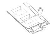
- FIG. 2 is a diagram showing an example of a state in which a cover tape is bonded (heat sealed) to a carrier tape.
- X to Y in the explanation of a numerical range means from X to Y, unless otherwise specified.
- X to Y means from X to Y, unless otherwise specified.
- 1 to 5% by mass means "from 1% by mass to 5% by mass.”
- (meth)acrylic refers to a concept that encompasses both acrylic and methacrylic. The same applies to similar terms such as "(meth)acrylate.”
- FIG. 1 is a schematic diagram showing an example of a layer structure of a cover tape (cover tape 10) for packaging electronic components according to the present embodiment.
- the cover tape 10 comprises a base layer 1 and a sealant layer 3 provided on at least one side of the base layer 1 .
- the cover tape 10 preferably includes an intermediate layer 2 between the base layer 1 and the sealant layer 3 .
- the sealant layer 3 contains a conductive polymer.
- Sample A is obtained by heat sealing the surface of the sealant layer 3 of the cover tape 10 to a polystyrene film according to the procedure described below in [Heat sealing procedure], and the peel strength obtained when the sample A is peeled under the conditions described below in [Peeling conditions] is defined as F A.
- Sample A is placed in an environment of 40° C. temperature and 90% relative humidity for 7 days, and the peel strength measured when the sample is peeled under the conditions described below in [Peeling Conditions] is designated as F B.
- the value of F B /F A is 0.6 to 1.4, preferably 0.65 to 1.35, more preferably 0.7 to 1.3, particularly preferably 0.7 to 1.25, and particularly preferably 0.7 to 1.2.
- the value of F B /F A is ideally 1, so that the value of F B /F A may exceed 1 as a result of designing the sealant layer 3.
- Heat sealing procedure (1) The sealant layer side of a cover tape cut to a width of 5.5 mm is mated with the uneven surface side of a polystyrene film having an average surface roughness (Ra) of 0.25 ⁇ m and a width of 8 mm to obtain a laminate.
- a two-blade iron one of which is 0.4 mm wide and 28 mm long, is brought into contact with the cover tape side of the laminate to heat seal it under conditions of a sealing temperature of 160°C, a load of 5 kgf, a sealing time of 60 milliseconds, and a carrier tape feed pitch of 4 mm.
- a sealing temperature 160°C
- a load of 5 kgf 5 kgf
- a sealing time 60 milliseconds
- carrier tape feed pitch 4 mm.
- the inventors have investigated from various perspectives the cause of the problem found in the preliminary study mentioned above, namely, the phenomenon that peeling easily occurs between the cover tape and the carrier tape during and after transportation by sea freight for electronic component packages in which a cover tape containing a conductive material in the sealant layer is attached to a carrier tape.
- a cover tape 10 containing a conductive material in the sealant layer 3 is heat-sealed to a polystyrene film (polystyrene is a material frequently used for carrier tapes) to prepare a sample A.
- the peel strength when the cover tape is peeled from this sample A under specific conditions is F A
- B Sample A is placed in an environment of 40° C. and 90% relative humidity for 7 days to prepare sample B. The cover tape is peeled off from sample B under specific conditions to obtain a peel strength F B .
- the cover tape 10 can be manufactured by using an appropriate material and a suitable manufacturing process.
- An example of "using an appropriate material” is to use a conductive polymer that is dissolved or dispersed in an organic solvent, rather than dispersed in water. The materials and manufacturing process for producing the cover tape 10 will be described in detail later.
- Base layer There are no particular limitations on the material that constitutes the base material layer 1. Any film can be used as long as it has the mechanical strength sufficient to withstand the external force applied to the cover tape 10 and the heat resistance sufficient to withstand the heat during heat sealing.
- the film used to form the base layer 1 may be a stretched film, or a film stretched uniaxially or biaxially. From the viewpoint of improving the mechanical strength of the cover tape 10, a film stretched uniaxially or biaxially is preferable.
- the substrate layer 1 may be a single layer or a multilayer.
- the base layer 1 may contain an antistatic agent from the viewpoint of reducing the amount of static electricity generated by peeling off the carrier tape.
- an antistatic layer may be provided as one layer of the base layer on the surface of the base layer 1 opposite to the surface on which the intermediate layer 2 is provided.
- the thickness of the substrate layer 1 is, for example, 6 to 35 ⁇ m, preferably 7 to 33 ⁇ m, and more preferably 8 to 30 ⁇ m. Since the base layer 1 is not too thick, the rigidity of the cover tape is not too high. Even if a torsional stress is applied to the carrier tape after sealing, the cover tape 10 follows the deformation of the carrier tape, reducing the possibility of peeling off. Since the thickness of the base material layer 1 is not too thin, it is easy to make the mechanical strength of the cover tape 10 suitable. Furthermore, even when the cover tape 10 is peeled off from the carrier tape at high speed, the possibility that the cover tape 10 will break can be reduced.
- the intermediate layer 2 is an optional layer, but is provided primarily for the purpose of improving the cushioning properties of the cover tape 10.
- the cushioning properties of the cover tape 10 By improving the cushioning properties of the cover tape 10, the pressure of the sealing iron during heat sealing can be more easily and firmly transmitted to the cover tape 10. This can further improve the adhesion between the cover tape 10 and the carrier tape.
- the material of the intermediate layer 2 is not particularly limited. Any material that can impart cushioning properties to the cover tape 10 can be used without particular limitations. Examples include polyacrylic acid derivatives, polyacrylic acid ester derivatives, polyvinyl acetate derivatives, styrene-based resins, olefin-based resins, cyclic olefin resins, and copolymers thereof. Among these, olefin-based resins are preferred, and ethylene-based resins are more preferred.
- the intermediate layer 2 may contain only one resin, or may contain two or more resins.
- the intermediate layer 2 may be a single layer or a multilayer.
- the thickness of the intermediate layer 2 is typically 10 to 50 ⁇ m, and preferably 15 to 45 ⁇ m, from the viewpoint of further improving the adhesion between the cover tape 10 and the carrier tape during heat sealing.
- the sealant layer 3 is provided on at least one side of the base layer 1.
- the sealant layer 3 is provided on the side of the intermediate layer 2 opposite to the side in contact with the base layer 1.
- the sealant layer 3 is preferably in direct contact with the intermediate layer 2.
- the sealant layer 3 comes into contact with the carrier tape when the cover tape 10 is heat-sealed to the carrier tape.
- the sealant layer 3 softens or melts when heated by the sealing iron, and adheres to the carrier tape.
- the sealant layer 3 preferably contains a thermoplastic resin.
- the sealant layer 3 contains one or more resins selected from styrene-based resins, (meth)acrylic resins, olefin-based resins, urethane-based resins, and ester-based resins.
- styrene-based resins and (meth)acrylic resins are preferred from the viewpoints of good heat sealability and good dissolving or dispersing of conductive polymers.
- the sealant layer 3 may contain only one resin, or may contain two or more resins.
- styrene-based resins include polystyrene, styrene-butadiene copolymer (SB), styrene-butadiene-styrene block copolymer (SBS), styrene-ethylene-butadiene-styrene block copolymer (SEBS), styrene-isoprene-styrene block copolymer (SIS), styrene-ethylene-propylene-styrene block copolymer (SEPS), styrene-methyl (meth)acrylate copolymer, hydrogenated styrene block copolymer, high impact polystyrene (HIPS; High Impact Polystyrene), general purpose polystyrene resin (GPPS; General Purpose Polystyrene), etc.
- SB styrene-butadiene copolymer
- SB styrene-
- (meth)acrylic resins include acrylic acid, methacrylic acid, methyl acrylate, ethyl acrylate, butyl acrylate, 2-ethylhexyl acrylate, and other acrylic acid esters; methacrylic acid esters, such as methyl methacrylate, ethyl methacrylate, butyl methacrylate, and other methacrylic acid esters; and resins having structural units derived from monomers such as acrylonitrile, methacrylonitrile, and acrylamide.
- (Meth)acrylic resins can contain structural units derived from one or more of these exemplified monomers. Of course, (meth)acrylic resins may further contain structural units derived from monomers other than these exemplified monomers.
- the ester resin usually comprises a structural unit derived from an alcohol component and a structural unit derived from a carboxylic acid component.
- the alcohol component include ethylene glycol, 1,2-propanediol, 1,3-propanediol, 1,2-butanediol, 1,3-butanediol, 1,4-butanediol, 2,3-butanediol, 2,2-dimethyl-1,3-propanediol, 1,6-hexanediol, 1,8-octanediol, 1,9-nonanediol, 1,10-decanediol, and 1,12-dodecanediol, and other chain or branched aliphatic diols, alicyclic diols such as hydrogenated bisphenol A [2,2-bis(4-hydroxycyclohexyl)propane] and hydrogenated bisphenol A with an alkylene oxide (average molar addition
- carboxylic acid component examples include aliphatic dicarboxylic acids such as oxalic acid, malonic acid, maleic acid, fumaric acid, citraconic acid, itaconic acid, glutaconic acid, succinic acid, adipic acid, sebacic acid, dodecanedioic acid, azelaic acid, dodecylsuccinic acid, dodecenylsuccinic acid, and octenylsuccinic acid, polyvalent carboxylic acids having three or more valences such as trimellitic acid or its anhydride, and aromatic dicarboxylic acids such as phthalic acid, isophthalic acid, and terephthalic aromatic dicarboxylic acid. These carboxylic acid components may be used alone or in combination.
- aliphatic dicarboxylic acids such as oxalic acid, malonic acid, maleic acid, fumaric acid, citraconic acid, itaconic acid, glutaconic acid, succinic
- the sealant layer 3 contains a conductive polymer in order to suppress the generation and charging of static electricity by making the sealant layer 3 conductive.
- the sealant layer 3 is composed of a mixture of a thermoplastic resin, such as a styrene-based resin or a (meth)acrylic resin, and a conductive polymer.
- ⁇ -conjugated conductive polymers are preferred in terms of good conductivity and easy availability.
- Specific conductive polymers include polypyrroles, polythiophenes, polyacetylenes, polyphenylenes, polyphenylenevinylenes, polyanilines, polyacenes, polythiophenevinylenes, and copolymers thereof. In terms of stability in air, polypyrroles, polythiophenes, and polyanilines are preferred.
- ⁇ -conjugated conductive polymers include polypyrrole, poly(N-methylpyrrole), poly(3-methylpyrrole), poly(3-ethylpyrrole), poly(3-n-propylpyrrole), poly(3-butylpyrrole), poly(3-octylpyrrole), poly(3-decylpyrrole), poly(3-dodecylpyrrole), poly(3,4-dimethylpyrrole), poly(3,4-dibutylpyrrole), poly(3-carboxypyrrole), poly(3-methyl-4-carboxypyrrole), poly(3-methyl-4-carboxyethylpyrrole), and poly(3-methyl-4-carboxybutylpyrrole).
- pyrrole poly(3-hydroxypyrrole), poly(3-methoxypyrrole), poly(3-ethoxypyrrole), poly(3-butoxypyrrole), poly(3-methyl-4-hexyloxypyrrole), poly(thiophene), poly(3-methylthiophene), poly(3-ethylthiophene), poly(3-propylthiophene), poly(3-butylthiophene), poly(3-hexylthiophene), poly(3-heptylthiophene), poly(3-octylthiophene), poly(3-decylthiophene), poly(3-dodecylthiophene), poly(3-octadecylthiophene), poly( 3-bromothiophene), poly(3-chlorothiophene), poly(3-iodothiophene), poly(3-cyanothiophene), poly(3-phenyl
- the sealant layer 3 may contain a dopant for enhancing the conductivity of the conductive polymer in addition to the conductive polymer.
- a preferred example of the dopant is a polymer having an anionic functional group.
- polymers having an anionic functional group include polyvinyl sulfonic acid, polystyrene sulfonic acid, polyallyl sulfonic acid, polyacryl sulfonic acid, polymethacryl sulfonic acid, poly(2-acrylamido-2-methylpropane sulfonic acid), polyisoprene sulfonic acid, polyvinyl carboxylic acid, polystyrene carboxylic acid, polyallyl carboxylic acid, polyacryl carboxylic acid, polymethacryl carboxylic acid, poly(2-acrylamido-2-methylpropane carboxylic acid), polyisoprene carboxylic acid, polyacrylic acid, etc.
- polythiophenes i.e., conductive polymers containing a structure derived from thiophene or a thiophene derivative
- polythiophenes i.e., conductive polymers containing a structure derived from thiophene or a thiophene derivative
- polythiophenes poly(3,4-ethylenedioxythiophene) or its derivatives are particularly preferred from the viewpoint of maintaining and improving various performances.
- the proportion of conductive polymer in the sealant layer 3 is, for example, 1 to 50 mass %, preferably 2 to 45 mass %.
- the sealant layer 3 may also contain other additives such as a leveling agent and a conductive additive.
- the thickness of the sealant layer 3 is preferably 0.03 to 20 ⁇ m, more preferably 0.03 to 15 ⁇ m, from the viewpoint of shortening the heat sealing operation time and obtaining a strong seal strength.
- the cover tape 10 may or may not include additional layers different from the base layer 1 , the intermediate layer 2 and the sealant layer 3 .
- an anchor coat layer may be provided between the base layer 1 and the intermediate layer 2 to enhance adhesion.
- the overall thickness of the cover tape 10 is preferably 40 to 65 ⁇ m, and more preferably 45 to 60 ⁇ m.
- the haze value of the cover tape 10 measured in accordance with JIS K 7136 (2000) is preferably 5 to 25%, more preferably 5 to 20%. When the haze value is not too large, the visibility of the electronic components packaged with the cover tape 10 can be improved.
- the total light transmittance of the cover tape 10 measured in accordance with JIS K 7361-1 (1997) is preferably 80 to 100%, and more preferably 85 to 95%.
- the cover tape 10 includes a conductive polymer in the sealant layer 3 to improve electrical conductivity and antistatic properties. However, the cover tape 10 does not need to include conductive "particles" such as metal-containing particles. Thus, the cover tape 10 tends to have a relatively small haze and a relatively large total light transmittance.
- the surface resistance value of the exposed surface of the cover tape 10 on the sealant layer 3 side is preferably 1 ⁇ 10 4 to 1 ⁇ 10 11 ⁇ / ⁇ , and more preferably 1 ⁇ 10 5 to 1 ⁇ 10 10 ⁇ / ⁇ . Since the sealant layer 3 contains a conductive polymer, the surface resistance value of the exposed surface of the cover tape 10 on the sealant layer 3 side is small.
- F A is preferably 0.2 to 0.7N, more preferably 0.2 to 0.6N.
- the cover tape 10 can be manufactured by using appropriate materials and a suitable manufacturing process. A suitable manufacturing method and materials used in the manufacturing method will be described below.
- the intermediate layer 2 is formed on the surface of the base layer 1.
- the base layer 1 is preferably a film formed of an ester-based resin, an olefin-based resin, etc.
- the intermediate layer 2 can be formed by, for example, an extrusion lamination method or a dry lamination method.
- a layer of, for example, an anchor coating agent may be present between the base layer 1 and the intermediate layer 2.
- a coating liquid for forming a sealant layer is applied onto the surface of the intermediate layer 2 opposite to the substrate layer 1, and then dried.
- a coating method for example, a gravure coating method can be adopted.
- the coating liquid for forming the sealant layer can typically be obtained by thoroughly mixing a resin (preferably a thermoplastic resin such as the above-mentioned styrene-based resin or (meth)acrylic-based resin), a conductive polymer, and a solvent capable of dissolving or dispersing these.
- a cover tape 10 having an F B /F A value of 0.6 to 1.4 it is preferable to select a conductive polymer that is soluble or dispersible in an organic solvent, and to select an organic solvent as the solvent.
- polythiophenes that are soluble or dispersible in an organic solvent as the conductive polymer.
- the conductive polymer being soluble in an organic solvent means, for example, that the conductive polymer is dissolved in the sealant layer-forming coating liquid described below and leaves no residue.
- Conductive polymers that are soluble or dispersible in organic solvents can be said to be lipophilic, i.e., hydrophobic. It is believed that the sealant layer 3 containing a hydrophobic conductive polymer is less likely to absorb moisture even in high temperature and high humidity environments. Therefore, by using a conductive polymer that is soluble in organic solvents, it is easy to manufacture a cover tape 10 having an F B /F A value of 0.6 to 1.4.
- Conductive polymers that are soluble or dispersible in organic solvents are commercially available from, for example, Matsuo Sangyo Co., Ltd.
- PEDOT/PSS poly(3,4-ethylenedioxythiophene):polystyrenesulfonic acid
- most conventional PEDOT/PSS is supplied as an aqueous dispersion (Reference: Chemistry and Education, Vol. 67, No. 2 (2019), pp. 86-89) and is not intended to be dissolved in an organic solvent for use.
- F B /F A may be adjusted by various measures while using PEDOT/PSS supplied as an aqueous dispersion.
- F B /F A may be adjusted by various measures while using PEDOT/PSS supplied as an aqueous dispersion.
- a cover tape 10 having an F B /F A value of 0.6 to 1.4 relatively easily and at low cost, it is preferable to use a conductive polymer that is soluble in an organic solvent.
- An electronic component package can be obtained from the cover tape 10 described above and a carrier tape having electronic components housed in recesses. This will be described with reference to FIG.
- a cover tape 10 for packaging electronic components is used as a lid material for a strip-shaped carrier tape 20 having recessed pockets 21 continuously formed to match the shapes of electronic components.
- the cover tape 10 for packaging electronic components is adhered (usually by heat sealing) to the surface of the carrier tape 20 so as to cover the entire opening of the pocket 21 of the carrier tape 20.
- the structure obtained by adhering the cover tape 10 for packaging electronic components and the carrier tape 20 together will be referred to as the electronic component package 100.
- the electronic component packaging body 100 can be produced, for example, by the following procedure. First, electronic components are placed in the pockets 21 of the carrier tape 20 . Next, the cover tape 10 for packaging electronic components is adhered to the surface of the carrier tape 20 by a heat sealing method so as to cover the entire opening of the pocket 21 of the carrier tape 20. At this time, the sealant layer 3 of the cover tape 10 for packaging electronic components is in contact with the carrier tape 20 (i.e., the heat sealing is performed so that the "back surface" of the cover tape 10 for packaging electronic components in FIG. 2 becomes the sealant layer 3).
- the specific method and conditions of heat sealing are not particularly limited as long as the cover tape 10 for packaging electronic components is sufficiently strongly adhered to the carrier tape 20. Typically, a known heat sealing machine can be used, and the heat sealing can be performed at a temperature of 100 to 240° C., a load of 0.1 to 10 kgf, and a time of 0.0001 to 1 second.
- a structure (electronic component packaging body 100) in which electronic components are hermetically housed is obtained.
- This structure (electronic component packaging body 100) is, for example, wound on a reel and stored until the electronic components are used.
- the reel on which electronic component packaging body 100 is wound may be transported to a remote location by sea or air freight.
- F B /F A since the value of F B /F A is 0.6 to 1.4, peeling of cover tape 10 from carrier tape 20 is suppressed even during transportation by sea freight, which may be subject to high temperature and high humidity.
- the reel may be made of metal, paper, plastic, or the like.
- the cover tape 10 for packaging electronic components is peeled off from the carrier tape 20, and the housed electronic components are taken out.
- the electronic components contained in electronic component packaging 100 include general components used in the manufacture of electric and electronic devices, such as semiconductor chips, transistors, diodes, capacitors, piezoelectric elements, optical elements, LED-related members, connectors, and electrodes.
- a coating solution for forming a sealant layer (non-volatile component concentration adjusted to 12.5% by mass) in which the materials shown in the "Sealant Layer” column in Table 1 were sufficiently dissolved or dispersed in methyl ethyl ketone was applied to the intermediate layer side of the obtained laminated film by gravure coating.
- the resulting three-layer film was cut to a width of 5.5 mm to make a cover tape.
- This laminate was heat sealed using a two-blade iron with one edge measuring 0.4 mm wide and 28 mm long under the conditions of a seal temperature of 180° C., a load of 5 kgf, a seal time of 60 milliseconds, a carrier tape feed pitch of 4 mm, and two rows and seven strikes using a heat sealer (Tokyo Wells Co., Ltd., “TWA-6621”). Sample A was thus obtained. Incidentally, in order to prepare Sample B below, at least two Samples A were prepared in each of the Examples and Comparative Examples. Using the obtained sample A, the peel strength (N) immediately after heat sealing of the cover tape to the polystyrene film was measured while referring to the description of JIS C0806-3.
- the peeling was performed using a peel tester (EPI's "PTS-5000") at 25°C, a peel speed of 300 mm/min, and a peel angle of 170°, and the peel strength was continuously recorded. Then, from the relationship between the recorded time and the peel strength, the average value of the peel strength for 10 seconds immediately after the start of peeling was calculated. This average value was adopted as F A.
- the surface roughness (Ra) of the polystyrene film was measured for the portion of the polystyrene film that was to be joined to the cover tape, in accordance with JIS B 0601 (2001), using a surface roughness measuring device (Mitutoyo Corporation's "SJ-210”) before bonding to the cover tape.
- Sample A was also placed in an environment with a temperature of 40° C. and a relative humidity of 90% for 7 days, thereby obtaining Sample B.
- Sample B was then peeled under the same peeling conditions as Sample A.
- ⁇ Surface resistance value of sealant layer side> The surface resistance ( ⁇ / ⁇ ) of the sealant layer surface of the obtained cover tape was measured in an environment of 25° C. and 50% RH using a surface resistance measuring device manufactured by SIMCO ("ST-3" manufactured by SIMCO).
- the total light transmittance (%) of the resulting cover tape was measured in accordance with JIS K 7361-1 (1997) using a Haze Meter NDH 2000 manufactured by Nippon Denshoku Kogyo Co., Ltd. under a light source of D65.
- a heat sealer (Tokyo Wells Co., Ltd., TWA-6621) equipped with a two-blade iron with a single blade of 0.4 mm width and 28 mm length was used under the conditions of a sealing temperature of 180 ° C, a load of 5 kgf, a sealing time of 60 milliseconds, a carrier tape feed pitch of 4 mm, and two rows and seven strikes.
- the sealing temperature was adjusted appropriately based on 180 ° C, so that the initial peel strength obtained under the conditions of 25 ° C, a peel speed of 300 mm / min, and a peel angle of 170 ° was 0.20 N.
- the initial peel strength was set to a relatively small value of 0.20 N to intentionally make peeling more likely to occur in high temperature and high humidity environments, making it easier to evaluate performance. If peeling is unlikely to occur even if the initial peel strength is small, it can be said to exhibit extremely excellent performance in practical use.
- (2) The evaluation sample obtained in (1) above was aged for 7 days in an environment of a temperature of 40° C. and a relative humidity of 90%.
- (3) The evaluation sample after aging was cut into a strip of 10 cm length, and one end of the strip was twisted 180° relative to the other end. It was then returned to its original position, twisted 180° in the opposite direction, and returned to its original position. This motion (once each in the forward and reverse directions) was repeated a total of five times.
- Base material layer 2 Intermediate layer 3: Sealant layer 10: Cover tape 20: Carrier tape 21: Pocket 100: Electronic component package
Landscapes
- Engineering & Computer Science (AREA)
- Mechanical Engineering (AREA)
- Laminated Bodies (AREA)
- Packaging Frangible Articles (AREA)
- Packages (AREA)
Priority Applications (2)
| Application Number | Priority Date | Filing Date | Title |
|---|---|---|---|
| JP2025505292A JPWO2024185677A1 (https=) | 2023-03-08 | 2024-03-01 | |
| CN202480017166.6A CN120752188A (zh) | 2023-03-08 | 2024-03-01 | 盖带、电子部件包装体及盖带的制造方法 |
Applications Claiming Priority (2)
| Application Number | Priority Date | Filing Date | Title |
|---|---|---|---|
| JP2023-035462 | 2023-03-08 | ||
| JP2023035462 | 2023-03-08 |
Publications (1)
| Publication Number | Publication Date |
|---|---|
| WO2024185677A1 true WO2024185677A1 (ja) | 2024-09-12 |
Family
ID=92675085
Family Applications (1)
| Application Number | Title | Priority Date | Filing Date |
|---|---|---|---|
| PCT/JP2024/007733 Ceased WO2024185677A1 (ja) | 2023-03-08 | 2024-03-01 | カバーテープ、電子部品包装体およびカバーテープの製造方法 |
Country Status (4)
| Country | Link |
|---|---|
| JP (1) | JPWO2024185677A1 (https=) |
| CN (1) | CN120752188A (https=) |
| TW (1) | TWI892499B (https=) |
| WO (1) | WO2024185677A1 (https=) |
Citations (8)
| Publication number | Priority date | Publication date | Assignee | Title |
|---|---|---|---|---|
| JP2005126081A (ja) * | 2003-10-21 | 2005-05-19 | Shin Etsu Polymer Co Ltd | カバーテープ用樹脂組成物、およびこれを用いたカバーテープ、並びに包装体 |
| JP2014501185A (ja) * | 2010-12-17 | 2014-01-20 | スリーエム イノベイティブ プロパティズ カンパニー | ヒートシール、及び電子部品をパッケージングするためのカバーテープ |
| JP2015182342A (ja) * | 2014-03-25 | 2015-10-22 | 三井化学東セロ株式会社 | カバーテープ用シーラントフィルム及びカバーテープ |
| JP2016182989A (ja) * | 2015-03-27 | 2016-10-20 | 住友ベークライト株式会社 | 電子部品包装用カバーテープ、電子部品包装用包材、および電子部品包装体 |
| CN108582903A (zh) * | 2018-06-21 | 2018-09-28 | 北京康得新功能材料有限公司 | 一种电子元器件用包装复合膜 |
| JP2021176674A (ja) * | 2020-03-17 | 2021-11-11 | 大日本印刷株式会社 | 電子部品包装用カバーテープおよび包装体 |
| JP2022081138A (ja) * | 2020-11-19 | 2022-05-31 | 住友ベークライト株式会社 | 電子部品包装用カバーテープ |
| JP2022158849A (ja) * | 2021-03-31 | 2022-10-17 | 住友ベークライト株式会社 | 電子部品包装用カバーテープおよび電子部品包装体 |
Family Cites Families (6)
| Publication number | Priority date | Publication date | Assignee | Title |
|---|---|---|---|---|
| JP3563863B2 (ja) * | 1996-02-09 | 2004-09-08 | 大日本印刷株式会社 | カバーテープ |
| US6027802A (en) * | 1997-10-23 | 2000-02-22 | Four Piliars Enterprise Co., Ltd. | Cover tape for packaging |
| JP3425547B2 (ja) * | 1999-12-27 | 2003-07-14 | 電気化学工業株式会社 | イージーピールフィルム |
| WO2013029261A1 (en) * | 2011-09-01 | 2013-03-07 | 3M Innovative Properties Company | Heat-sealing cover film for packaging electronic components |
| CN105377713A (zh) * | 2013-07-09 | 2016-03-02 | 住友电木株式会社 | 电子部件包装用盖带 |
| JP2021080024A (ja) * | 2019-11-15 | 2021-05-27 | 住友ベークライト株式会社 | カバーテープおよび電子部品包装体 |
-
2024
- 2024-03-01 WO PCT/JP2024/007733 patent/WO2024185677A1/ja not_active Ceased
- 2024-03-01 CN CN202480017166.6A patent/CN120752188A/zh active Pending
- 2024-03-01 JP JP2025505292A patent/JPWO2024185677A1/ja active Pending
- 2024-03-07 TW TW113108312A patent/TWI892499B/zh active
Patent Citations (8)
| Publication number | Priority date | Publication date | Assignee | Title |
|---|---|---|---|---|
| JP2005126081A (ja) * | 2003-10-21 | 2005-05-19 | Shin Etsu Polymer Co Ltd | カバーテープ用樹脂組成物、およびこれを用いたカバーテープ、並びに包装体 |
| JP2014501185A (ja) * | 2010-12-17 | 2014-01-20 | スリーエム イノベイティブ プロパティズ カンパニー | ヒートシール、及び電子部品をパッケージングするためのカバーテープ |
| JP2015182342A (ja) * | 2014-03-25 | 2015-10-22 | 三井化学東セロ株式会社 | カバーテープ用シーラントフィルム及びカバーテープ |
| JP2016182989A (ja) * | 2015-03-27 | 2016-10-20 | 住友ベークライト株式会社 | 電子部品包装用カバーテープ、電子部品包装用包材、および電子部品包装体 |
| CN108582903A (zh) * | 2018-06-21 | 2018-09-28 | 北京康得新功能材料有限公司 | 一种电子元器件用包装复合膜 |
| JP2021176674A (ja) * | 2020-03-17 | 2021-11-11 | 大日本印刷株式会社 | 電子部品包装用カバーテープおよび包装体 |
| JP2022081138A (ja) * | 2020-11-19 | 2022-05-31 | 住友ベークライト株式会社 | 電子部品包装用カバーテープ |
| JP2022158849A (ja) * | 2021-03-31 | 2022-10-17 | 住友ベークライト株式会社 | 電子部品包装用カバーテープおよび電子部品包装体 |
Also Published As
| Publication number | Publication date |
|---|---|
| CN120752188A (zh) | 2025-10-03 |
| TWI892499B (zh) | 2025-08-01 |
| JPWO2024185677A1 (https=) | 2024-09-12 |
| TW202442552A (zh) | 2024-11-01 |
Similar Documents
| Publication | Publication Date | Title |
|---|---|---|
| JP3966171B2 (ja) | 積層フィルム、および、積層フィルムの製造方法 | |
| TWI620695B (zh) | 電子零件包裝用包裝體 | |
| CN103153810A (zh) | 电子部件包装用盖带 | |
| TW200302164A (en) | Laminated film and process for producing laminated film | |
| WO2012169387A1 (ja) | カバーフィルム | |
| JP5463193B2 (ja) | カバーテープ | |
| JP2019172281A (ja) | カバーテープ、電子部品包装体およびカバーテープの製造方法 | |
| JP2014532602A (ja) | キャリアテープ用カバーテープ | |
| JP2020037691A (ja) | ディスプレイ用粘着シートおよびこれを含むディスプレイ | |
| WO2024185677A1 (ja) | カバーテープ、電子部品包装体およびカバーテープの製造方法 | |
| JP6880129B2 (ja) | ディスプレイ用粘着シートおよびこれを含むディスプレイ | |
| JP7672324B2 (ja) | 電子部品包装用カバーテープおよび電子部品包装体 | |
| TWI698491B (zh) | 導電性高分子分散液、導電性薄膜及其製造方法、以及抗靜電性容器及其製造方法 | |
| JP2025055876A (ja) | カバーテープおよび電子部品包装体 | |
| WO2022255338A1 (ja) | 電子部品包装用カバーテープおよび包装体 | |
| JP2015140200A (ja) | 電子部品包装用カバーテープ | |
| JP2025061310A (ja) | 電子部品包装用カバーテープ | |
| JP2009137618A (ja) | カバーテープおよびその製造方法、ならびに包装体 | |
| JP2025133188A (ja) | カバーテープ巻取品および電子部品包装体 | |
| JP2017064969A (ja) | 積層ポリエチレンテレフタレートフィルム | |
| CN104893610B (zh) | 一种防静电胶带 | |
| JP2002193377A (ja) | 電子部品包装用カバーテープ | |
| JP7683282B2 (ja) | 電子部品包装用カバーテープ、電子部品包装体および電子部品包装用カバーテープの製造方法 | |
| WO2022210158A1 (ja) | 電子部品包装用カバーテープおよび電子部品包装体 | |
| JP4569043B2 (ja) | 電子部品包装用カバーテープ |
Legal Events
| Date | Code | Title | Description |
|---|---|---|---|
| 121 | Ep: the epo has been informed by wipo that ep was designated in this application |
Ref document number: 24767045 Country of ref document: EP Kind code of ref document: A1 |
|
| WWE | Wipo information: entry into national phase |
Ref document number: 2025505292 Country of ref document: JP |
|
| WWE | Wipo information: entry into national phase |
Ref document number: 202480017166.6 Country of ref document: CN |
|
| WWP | Wipo information: published in national office |
Ref document number: 202480017166.6 Country of ref document: CN |
|
| NENP | Non-entry into the national phase |
Ref country code: DE |
|
| 122 | Ep: pct application non-entry in european phase |
Ref document number: 24767045 Country of ref document: EP Kind code of ref document: A1 |