WO2024185553A1 - ガス漏れ検査方法、ガス漏れ検査システム及びガス漏れ検査装置 - Google Patents
ガス漏れ検査方法、ガス漏れ検査システム及びガス漏れ検査装置 Download PDFInfo
- Publication number
- WO2024185553A1 WO2024185553A1 PCT/JP2024/006798 JP2024006798W WO2024185553A1 WO 2024185553 A1 WO2024185553 A1 WO 2024185553A1 JP 2024006798 W JP2024006798 W JP 2024006798W WO 2024185553 A1 WO2024185553 A1 WO 2024185553A1
- Authority
- WO
- WIPO (PCT)
- Prior art keywords
- gas
- container
- substance
- leak inspection
- detection
- Prior art date
- Legal status (The legal status is an assumption and is not a legal conclusion. Google has not performed a legal analysis and makes no representation as to the accuracy of the status listed.)
- Ceased
Links
Images
Classifications
-
- G—PHYSICS
- G01—MEASURING; TESTING
- G01M—TESTING STATIC OR DYNAMIC BALANCE OF MACHINES OR STRUCTURES; TESTING OF STRUCTURES OR APPARATUS, NOT OTHERWISE PROVIDED FOR
- G01M3/00—Investigating fluid-tightness of structures
- G01M3/02—Investigating fluid-tightness of structures by using fluid or vacuum
- G01M3/04—Investigating fluid-tightness of structures by using fluid or vacuum by detecting the presence of fluid at the leakage point
- G01M3/20—Investigating fluid-tightness of structures by using fluid or vacuum by detecting the presence of fluid at the leakage point using special tracer materials, e.g. dye, fluorescent material, radioactive material
Definitions
- the present disclosure relates to a gas leak inspection method, a gas leak inspection system, and a gas leak inspection device.
- This application claims priority based on Japanese Patent Application No. 2023-035698, filed on March 8, 2023, the disclosure of which is incorporated herein in its entirety.
- Patent Document 1 discloses a method (pinhole inspection method) for inspecting whether or not there are pinholes or defective seals in a sealed package.
- a test gas container filled with a test gas e.g., He gas
- a gas detector that detects the test gas is used to inspect whether or not the test gas has leaked outside the sealed package.
- Patent Document 1 requires a process for sealing the test gas in a test gas container, and a process for exhausting the test gas floating in the atmosphere during this gas sealing process, so there are many steps required for gas leak testing, making it cumbersome.
- the need to purchase test gas tends to increase the cost of gas leak testing.
- This disclosure has been made in consideration of the above-mentioned circumstances.
- the purpose of this disclosure is to provide a gas leak inspection method, a gas leak inspection system, and a gas leak inspection device that can easily and inexpensively inspect containers for gas leaks.
- One aspect of the present disclosure is a gas leak inspection method that includes storing a substance that generates a detection gas in a container, and measuring the detection gas released from the substance into the container outside the container, thereby inspecting for leakage of the detection gas outside the container.
- One aspect of the present disclosure is a gas leak inspection system that includes a container, a substance that is contained in the container and generates a detection gas, and a gas leak inspection device that measures the detection gas outside the container to inspect for leakage of the detection gas outside the container.
- One aspect of the present disclosure is a gas leak inspection device that inspects for leakage of a detection gas to the outside of a container that contains a substance that generates the detection gas by measuring the detection gas outside the container.
- gas leak inspection of containers can be carried out easily and inexpensively.
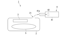
- FIG. 1 is a diagram illustrating a gas leak inspection system according to an embodiment.
- the gas leak inspection system 1 of this embodiment includes a container 2, a substance 3 contained in the container 2, and a gas leak inspection device 4.
- a product 5 is contained in the container 2 together with the substance 3.
- the product 5 may be, for example, food or medicine. Therefore, the container 2 of this embodiment functions as a packaging container for packaging the product 5.
- the container 2 is sealed in a state in which the substance 3 and the product 5 are contained.
- the container 2 may be flexible by being made of a resin film or the like, or may be inflexible by being made of a resin or the like.
- Substance 3 generates the detection gas.
- substance 3 is a quality preservation substance for preserving the quality of product 5 contained in container 2.
- substance 3 in this embodiment generates the detection gas by chemically reacting with other substances in container 2.
- Substance 3 may be contained in container 2, for example, in a bag (film bag) made of a gas-permeable film.
- the substance 3 in this embodiment is an iron-based oxygen absorber.
- the iron-based oxygen absorber chemically reacts with oxygen (O 2 ) or water (H 2 O) to generate hydrogen gas as the detection gas.
- the water that reacts with the iron-based oxygen absorber may exist as water vapor or liquid in the container 2.
- the iron-based oxygen absorber absorbs oxygen in the container 2, thereby suppressing the growth of mold and spoilage of the product 5.
- the iron-based oxygen absorber functions as a quality preserving substance that preserves the quality of the product 5 contained in the container 2.
- the gas leak inspection device 4 inspects for leakage of the detection gas to the outside of the sealed container 2 by measuring the detection gas outside the container 2.
- the gas leak inspection device 4 measures the concentration of the detection gas. Furthermore, based on the measured concentration of the detection gas, the gas leak inspection device 4 determines whether or not the detection gas is leaking from the inside to the outside of the container 2.
- the gas leak inspection device 4 may, for example, determine that the detection gas is leaking outside the container 2 when the measured concentration of the detection gas is greater than a predetermined threshold, and may determine that the detection gas is not leaking outside the container 2 when the measured concentration of the detection gas is equal to or less than the predetermined threshold.
- the above “threshold” may be 0% or a predetermined numerical value equal to or greater than 0%.
- a “threshold” of 0% means that the gas leak inspection device 4 inspects the presence or absence of the detection gas outside the container 2.
- the housing 41 includes a housing 41 having an opening 41a and a gas sensor 42 housed in the housing 41.
- the gas sensor 42 measures the detection gas.
- the detection gas can be measured by the detection gas entering the inside of the housing 41 through the opening 41a of the housing 41 and reaching the gas sensor 42.
- the opening 41a of the housing 41 can be moved close to the outer surface of the container 2 or moved along the outer surface of the container 2, so that the gas sensor 42 can measure the detection gas leaking to the outside of the container 2.
- the gas leak inspection device 4 can be moved so that the opening 41a of the housing 41 moves along the outer surface of the container 2, and the position of the container 2 from which the detection gas is leaking (the position of the hole 21 opened in the container 2) can be detected based on the position of the opening 41a of the housing 41 and the measured concentration of the detection gas. Since the detection gas in this embodiment is hydrogen gas, the gas sensor 42 measures hydrogen gas.
- a substance 3 that generates a detection gas is placed in a container 2.
- a product 5 such as food or medicine is placed in the container 2 together with the substance 3.
- the container 2 is then sealed.
- the detection gas released from the substance 3 into the container 2 is measured outside the container 2. In this way, leakage of the detection gas to the outside of the container 2 is inspected.
- a gas leak inspection device 4 is used to measure the detection gas outside the container 2.
- the substance 3 in the gas leak inspection method of this embodiment is an iron-based deoxidizer.
- the detection gas released from the substance 3 leaks to the outside through the hole 21 in the container 2, and the detection gas that has leaked to the outside is measured by the gas leak inspection device 4 at a concentration higher than a predetermined concentration (threshold). If the container 2 does not have a hole 21, the detection gas released from the substance 3 does not leak to the outside of the container 2, and the gas leak inspection device 4 measures the detection gas at a concentration lower than the predetermined concentration (threshold).
- measurement of the detection gas outside the container 2 may be started immediately after the container 2 is sealed. However, it may take some time for the pressure of the detection gas inside the container 2 to increase after the container 2 is sealed. For this reason, for example, measurement of the detection gas outside the container 2 may be started after a predetermined time has elapsed after the container 2 is sealed.
- a detection gas is generated from a substance 3 contained in a container 2. This eliminates the need for a process of sealing the detection gas in the container 2 and a process of exhausting the detection gas floating in the atmosphere during the gas sealing process when inspecting a container 2 for gas leaks. Therefore, a gas leak inspection of a container 2 can be performed easily and inexpensively.
- the substance 3 contained in the container 2 is an iron-based deoxidizer that chemically reacts with oxygen or water to generate hydrogen gas as the detection gas.
- hydrogen gas about 0.5 ppm
- the detection gas it is possible to test for gas leaks from the container 2 in the atmosphere.
- the gas leak test can be performed easily and inexpensively.
- the "other substances” that are chemically reacted with the iron-based deoxidizer to produce hydrogen gas are oxygen or water, which are abundant in the atmosphere, there is no need to prepare the "other substances" in advance, making gas leak testing even cheaper and easier.
- the iron-based deoxidizer as the substance 3 contained in the container 2 functions as a quality preserving substance for preserving the quality of the product 5 contained in the container 2.
- the substance 3 serves both the function of preserving the quality of the product 5 contained in the container 2 and the function of generating the detection gas. This makes it possible to inspect the container 2 for gas leaks and simultaneously preserve the quality of the product 5 without increasing the number of items (types) contained in the container 2, i.e., inexpensively.
- the substance 3 contained in the container 2 may be, for example, a non-ferrous oxygen absorber.
- the non-ferrous oxygen absorber releases carbon dioxide gas as the detection gas.
- the non-ferrous oxygen absorber absorbs oxygen in the container 2 to suppress the growth of mold and spoilage of the product 5, i.e., functions as a quality preserving substance that preserves the quality of the product 5 contained in the container 2. Therefore, the same effects as those of the above embodiment are achieved.
- the substance 3 is a non-ferrous oxygen absorber
- the carbon dioxide gas released from the non-ferrous oxygen absorber can be used to inspect the container 2 for gas leaks. Since the amount of carbon dioxide gas contained in the atmosphere is very small, the container 2 can be inspected for gas leaks in the atmosphere, as in the case of hydrogen gas.
- the substance 3 contained in the container 2 may be, for example, an ethanol transpiration agent.
- the ethanol transpiration agent transpires ethanol gas as the detection gas.
- the ethanol transpiration agent suppresses the growth of mold and the proliferation of microorganisms by the evaporated ethanol gas.
- the product 5 contains moisture such as food, it can also suppress the escape of moisture from the product 5. That is, the ethanol transpiration agent functions as a quality preservation material that preserves the quality of the product 5 contained in the container 2, similar to the oxygen absorber. Therefore, the same effect as the above embodiment is achieved.
- the substance 3 is an ethanol evaporant
- the ethanol gas evaporated from the ethanol evaporant can be used to inspect the container 2 for gas leaks. Since the amount of ethanol gas contained in the atmosphere is very small, the container 2 can be inspected for gas leaks in the atmosphere, similar to the case of hydrogen gas and carbon dioxide gas.
- the substance 3 contained in the container 2 may be, for example, a hydrogen molecule generating agent.
- the hydrogen molecule generating agent generates hydrogen gas as a detection gas by chemically reacting magnesium (Mg) contained in the hydrogen molecule generating agent with water (H 2 O).
- Mg magnesium
- H 2 O water
- the water that reacts with the hydrogen molecule generating agent may exist as water vapor or liquid in the container 2.
- the substance 3 contained in the container 2 may be, for example, a substance that emits an odor as a detection gas.
- the odor-emitting substance 3 may be, for example, a product 5 such as food or medicine contained in the container 2.
- the container 2 can be inspected for gas leaks by utilizing the smell generated from the substance 3. Also, since it is not necessary to put the substance 3 that generates the detection gas separately from the product 5, the number of items (types) stored in the container 2 can be minimized and the container 2 can be inspected for gas leaks at low cost.
- the container 2 that is the subject of the gas leak inspection may be one that has at least an internal cavity and that is required to be sealed.
- the container 2 that is the subject of the gas leak inspection is not limited to a packaging container that contains a product 5, but may also be, for example, a tire.
- This disclosure may be applied to gas leak inspection methods, gas leak inspection systems, and gas leak inspection devices.
- the present disclosure may be applied, for example, to gas leak testing of container 2 when container 2 is placed in a specified chamber and isolated from the atmosphere.
Landscapes
- Physics & Mathematics (AREA)
- General Physics & Mathematics (AREA)
- Examining Or Testing Airtightness (AREA)
Priority Applications (1)
| Application Number | Priority Date | Filing Date | Title |
|---|---|---|---|
| JP2025505234A JPWO2024185553A1 (https=) | 2023-03-08 | 2024-02-26 |
Applications Claiming Priority (2)
| Application Number | Priority Date | Filing Date | Title |
|---|---|---|---|
| JP2023-035698 | 2023-03-08 | ||
| JP2023035698 | 2023-03-08 |
Publications (1)
| Publication Number | Publication Date |
|---|---|
| WO2024185553A1 true WO2024185553A1 (ja) | 2024-09-12 |
Family
ID=92674931
Family Applications (1)
| Application Number | Title | Priority Date | Filing Date |
|---|---|---|---|
| PCT/JP2024/006798 Ceased WO2024185553A1 (ja) | 2023-03-08 | 2024-02-26 | ガス漏れ検査方法、ガス漏れ検査システム及びガス漏れ検査装置 |
Country Status (2)
| Country | Link |
|---|---|
| JP (1) | JPWO2024185553A1 (https=) |
| WO (1) | WO2024185553A1 (https=) |
Citations (8)
| Publication number | Priority date | Publication date | Assignee | Title |
|---|---|---|---|---|
| JPH03284347A (ja) * | 1990-03-30 | 1991-12-16 | Mitsubishi Gas Chem Co Inc | 脱酸素剤 |
| JPH05107240A (ja) * | 1991-10-18 | 1993-04-27 | Fuji Photo Film Co Ltd | 密閉性試験素子及び試験方法 |
| JPH07120347A (ja) * | 1993-08-31 | 1995-05-12 | Otsuka Pharmaceut Factory Inc | 密封包装体のピンホール検査方法 |
| JPH07198529A (ja) * | 1993-12-28 | 1995-08-01 | Otsuka Pharmaceut Factory Inc | 密封包装容器のピンホール検査方法 |
| JP2008224597A (ja) * | 2007-03-15 | 2008-09-25 | Kyushu Sankosha:Kk | 水蒸気移動制御装置を取り付けるための箱体を検査対象とした気密検査方法及び気密検査装置 |
| JP2010003456A (ja) * | 2008-06-18 | 2010-01-07 | Aquafairy Kk | 燃料電池 |
| JP2017035031A (ja) * | 2015-08-10 | 2017-02-16 | 国立研究開発法人農業・食品産業技術総合研究機構 | 発酵飼料の製造方法 |
| JP2017127214A (ja) * | 2016-01-19 | 2017-07-27 | 三菱瓦斯化学株式会社 | 炭酸ガスインジケーターを有する容器、及びこれを用いた炭酸ガス検知方法 |
-
2024
- 2024-02-26 JP JP2025505234A patent/JPWO2024185553A1/ja active Pending
- 2024-02-26 WO PCT/JP2024/006798 patent/WO2024185553A1/ja not_active Ceased
Patent Citations (8)
| Publication number | Priority date | Publication date | Assignee | Title |
|---|---|---|---|---|
| JPH03284347A (ja) * | 1990-03-30 | 1991-12-16 | Mitsubishi Gas Chem Co Inc | 脱酸素剤 |
| JPH05107240A (ja) * | 1991-10-18 | 1993-04-27 | Fuji Photo Film Co Ltd | 密閉性試験素子及び試験方法 |
| JPH07120347A (ja) * | 1993-08-31 | 1995-05-12 | Otsuka Pharmaceut Factory Inc | 密封包装体のピンホール検査方法 |
| JPH07198529A (ja) * | 1993-12-28 | 1995-08-01 | Otsuka Pharmaceut Factory Inc | 密封包装容器のピンホール検査方法 |
| JP2008224597A (ja) * | 2007-03-15 | 2008-09-25 | Kyushu Sankosha:Kk | 水蒸気移動制御装置を取り付けるための箱体を検査対象とした気密検査方法及び気密検査装置 |
| JP2010003456A (ja) * | 2008-06-18 | 2010-01-07 | Aquafairy Kk | 燃料電池 |
| JP2017035031A (ja) * | 2015-08-10 | 2017-02-16 | 国立研究開発法人農業・食品産業技術総合研究機構 | 発酵飼料の製造方法 |
| JP2017127214A (ja) * | 2016-01-19 | 2017-07-27 | 三菱瓦斯化学株式会社 | 炭酸ガスインジケーターを有する容器、及びこれを用いた炭酸ガス検知方法 |
Also Published As
| Publication number | Publication date |
|---|---|
| JPWO2024185553A1 (https=) | 2024-09-12 |
Similar Documents
| Publication | Publication Date | Title |
|---|---|---|
| US20040177676A1 (en) | Method and device for determining the permeation of a barrier layer | |
| US20040040372A1 (en) | Method for determining the permeation of gases into or out of plastic packages and for determination of shelf-life with respect to gas permeation | |
| RU2699960C2 (ru) | Проверка герметичности с помощью газа-носителя в пленочной камере | |
| KR0171635B1 (ko) | 가스 누출 검사 장치 및 방법 | |
| JP6602852B2 (ja) | グロスリーク検知のための容積測定機能を備えるフィルムチャンバ | |
| US6964191B1 (en) | Apparatus and technique for measuring permeability and permeant sorption | |
| US10670489B2 (en) | Device and method for calibrating a film chamber for leak detection | |
| CA2274509A1 (en) | Method for treating a product and leak-detection installation | |
| US9188501B2 (en) | Method for testing the tightness of water conducting components in a housing | |
| US20210048365A1 (en) | System and method for determining the integrity of containers | |
| Caner et al. | Effect of high‐pressure processing on the permeance of selected high‐barrier laminated films | |
| JP7462006B2 (ja) | 密封性評価のための疑似漏れ試験方法及び疑似漏れ試験装置 | |
| JP2021508372A (ja) | 光学的測定によって容器の健全性を判定するためのシステムおよび方法 | |
| AU2016376655A1 (en) | Gross leak measurement in an incompressible test item in a film chamber | |
| JP2017211223A (ja) | 密封された検査対象の評価方法及び評価装置 | |
| WO2024185553A1 (ja) | ガス漏れ検査方法、ガス漏れ検査システム及びガス漏れ検査装置 | |
| JP2026062747A (ja) | 液体入り組合せ容器、検査方法及び液体入り組合せ容器の製造方法 | |
| US11262268B2 (en) | Method for inspecting a seal of a flexible container | |
| JP2004219407A (ja) | ガス透過率測定方法およびガス透過率測定装置 | |
| US20140287521A1 (en) | Measuring Device for Tubular Bag Packaging Machines | |
| JPH01227037A (ja) | 漏れ試験機用容器 | |
| JP2003185520A (ja) | 容器のリーク検査方法とリーク検査装置 | |
| JP2006327621A (ja) | 密閉包装体のシール検査方法及び検査装置 | |
| JP3149004B2 (ja) | 密封包装袋のピンホール検査方法 | |
| JP2002527738A (ja) | 比較的薄い壁を有する試験体で積分法によるリークテストを実施する方法 |
Legal Events
| Date | Code | Title | Description |
|---|---|---|---|
| 121 | Ep: the epo has been informed by wipo that ep was designated in this application |
Ref document number: 24766924 Country of ref document: EP Kind code of ref document: A1 |
|
| ENP | Entry into the national phase |
Ref document number: 2025505234 Country of ref document: JP Kind code of ref document: A |
|
| WWE | Wipo information: entry into national phase |
Ref document number: 2025505234 Country of ref document: JP |
|
| NENP | Non-entry into the national phase |
Ref country code: DE |
|
| 122 | Ep: pct application non-entry in european phase |
Ref document number: 24766924 Country of ref document: EP Kind code of ref document: A1 |