WO2024185476A1 - 回転体駆動装置およびそれに使用される位置センサユニット - Google Patents
回転体駆動装置およびそれに使用される位置センサユニット Download PDFInfo
- Publication number
- WO2024185476A1 WO2024185476A1 PCT/JP2024/005731 JP2024005731W WO2024185476A1 WO 2024185476 A1 WO2024185476 A1 WO 2024185476A1 JP 2024005731 W JP2024005731 W JP 2024005731W WO 2024185476 A1 WO2024185476 A1 WO 2024185476A1
- Authority
- WO
- WIPO (PCT)
- Prior art keywords
- gear
- center line
- rotation center
- rotating body
- external teeth
- Prior art date
- Legal status (The legal status is an assumption and is not a legal conclusion. Google has not performed a legal analysis and makes no representation as to the accuracy of the status listed.)
- Ceased
Links
Images


Classifications
-
- F—MECHANICAL ENGINEERING; LIGHTING; HEATING; WEAPONS; BLASTING
- F16—ENGINEERING ELEMENTS AND UNITS; GENERAL MEASURES FOR PRODUCING AND MAINTAINING EFFECTIVE FUNCTIONING OF MACHINES OR INSTALLATIONS; THERMAL INSULATION IN GENERAL
- F16H—GEARING
- F16H37/00—Combinations of mechanical gearings, not provided for in groups F16H1/00 - F16H35/00
- F16H37/12—Gearings comprising primarily toothed or friction gearing, links or levers, and cams, or members of at least two of these types
- F16H37/16—Gearings comprising primarily toothed or friction gearing, links or levers, and cams, or members of at least two of these types with a driving or driven member which both rotates or oscillates on its axis and reciprocates
-
- F—MECHANICAL ENGINEERING; LIGHTING; HEATING; WEAPONS; BLASTING
- F16—ENGINEERING ELEMENTS AND UNITS; GENERAL MEASURES FOR PRODUCING AND MAINTAINING EFFECTIVE FUNCTIONING OF MACHINES OR INSTALLATIONS; THERMAL INSULATION IN GENERAL
- F16H—GEARING
- F16H1/00—Toothed gearings for conveying rotary motion
- F16H1/02—Toothed gearings for conveying rotary motion without gears having orbital motion
- F16H1/04—Toothed gearings for conveying rotary motion without gears having orbital motion involving only two intermeshing members
- F16H1/06—Toothed gearings for conveying rotary motion without gears having orbital motion involving only two intermeshing members with parallel axes
-
- F—MECHANICAL ENGINEERING; LIGHTING; HEATING; WEAPONS; BLASTING
- F16—ENGINEERING ELEMENTS AND UNITS; GENERAL MEASURES FOR PRODUCING AND MAINTAINING EFFECTIVE FUNCTIONING OF MACHINES OR INSTALLATIONS; THERMAL INSULATION IN GENERAL
- F16H—GEARING
- F16H37/00—Combinations of mechanical gearings, not provided for in groups F16H1/00 - F16H35/00
- F16H37/12—Gearings comprising primarily toothed or friction gearing, links or levers, and cams, or members of at least two of these types
-
- G—PHYSICS
- G02—OPTICS
- G02B—OPTICAL ELEMENTS, SYSTEMS OR APPARATUS
- G02B7/00—Mountings, adjusting means, or light-tight connections, for optical elements
- G02B7/02—Mountings, adjusting means, or light-tight connections, for optical elements for lenses
-
- G—PHYSICS
- G02—OPTICS
- G02B—OPTICAL ELEMENTS, SYSTEMS OR APPARATUS
- G02B7/00—Mountings, adjusting means, or light-tight connections, for optical elements
- G02B7/02—Mountings, adjusting means, or light-tight connections, for optical elements for lenses
- G02B7/04—Mountings, adjusting means, or light-tight connections, for optical elements for lenses with mechanism for focusing or varying magnification
- G02B7/08—Mountings, adjusting means, or light-tight connections, for optical elements for lenses with mechanism for focusing or varying magnification adapted to co-operate with a remote control mechanism
-
- G—PHYSICS
- G03—PHOTOGRAPHY; CINEMATOGRAPHY; ANALOGOUS TECHNIQUES USING WAVES OTHER THAN OPTICAL WAVES; ELECTROGRAPHY; HOLOGRAPHY
- G03B—APPARATUS OR ARRANGEMENTS FOR TAKING PHOTOGRAPHS OR FOR PROJECTING OR VIEWING THEM; APPARATUS OR ARRANGEMENTS EMPLOYING ANALOGOUS TECHNIQUES USING WAVES OTHER THAN OPTICAL WAVES; ACCESSORIES THEREFOR
- G03B17/00—Details of cameras or camera bodies; Accessories therefor
- G03B17/56—Accessories
-
- G—PHYSICS
- G03—PHOTOGRAPHY; CINEMATOGRAPHY; ANALOGOUS TECHNIQUES USING WAVES OTHER THAN OPTICAL WAVES; ELECTROGRAPHY; HOLOGRAPHY
- G03B—APPARATUS OR ARRANGEMENTS FOR TAKING PHOTOGRAPHS OR FOR PROJECTING OR VIEWING THEM; APPARATUS OR ARRANGEMENTS EMPLOYING ANALOGOUS TECHNIQUES USING WAVES OTHER THAN OPTICAL WAVES; ACCESSORIES THEREFOR
- G03B21/00—Projectors or projection-type viewers; Accessories therefor
- G03B21/14—Details
-
- H—ELECTRICITY
- H02—GENERATION; CONVERSION OR DISTRIBUTION OF ELECTRIC POWER
- H02K—DYNAMO-ELECTRIC MACHINES
- H02K7/00—Arrangements for handling mechanical energy structurally associated with dynamo-electric machines, e.g. structural association with mechanical driving motors or auxiliary dynamo-electric machines
- H02K7/10—Structural association with clutches, brakes, gears, pulleys or mechanical starters
- H02K7/116—Structural association with clutches, brakes, gears, pulleys or mechanical starters with gears
-
- F—MECHANICAL ENGINEERING; LIGHTING; HEATING; WEAPONS; BLASTING
- F16—ENGINEERING ELEMENTS AND UNITS; GENERAL MEASURES FOR PRODUCING AND MAINTAINING EFFECTIVE FUNCTIONING OF MACHINES OR INSTALLATIONS; THERMAL INSULATION IN GENERAL
- F16H—GEARING
- F16H25/00—Gearings comprising primarily only cams, cam-followers and screw-and-nut mechanisms
- F16H25/18—Gearings comprising primarily only cams, cam-followers and screw-and-nut mechanisms for conveying or interconverting oscillating or reciprocating motions
- F16H25/186—Gearings comprising primarily only cams, cam-followers and screw-and-nut mechanisms for conveying or interconverting oscillating or reciprocating motions with reciprocation along the axis of oscillation
Definitions
- This disclosure relates to a rotating body drive device that rotates a rotating body and a position sensor unit used therein.
- Patent Document 1 discloses a device that rotates a worm wheel (rotating body).
- a worm (drive gear) that meshes with the external teeth of the worm wheel is rotated by a motor.
- the worm gear is supported by a support base attached to the tip (free end) of a leaf spring.
- the leaf spring urges the worm toward the worm wheel. This eliminates backlash between the worm wheel and the worm. By eliminating the backlash, the rotational angle position of the worm wheel can be adjusted with high precision by the motor.
- the present disclosure aims to adjust the rotational angle position of a rotor with external teeth in a rotor drive device having a rotor with external teeth and a drive gear that rotates the rotor, with high precision, regardless of the presence or absence of backlash between the rotor's external teeth and the drive gear.
- a rotor having external teeth; a drive gear that meshes with the external teeth of the rotor and rotates about a rotation center line that is parallel to the rotation center line of the rotor; a position detection unit for detecting a rotation angle position of the rotating body,
- the position detection unit is Base member, a rotating member supported by the base member so as to be rotatable about a first rotation center line parallel to a rotation center line of the rotating body; a first gear supported by the rotating member so as to be rotatable about a second rotation center line parallel to the first rotation center line and meshing with external teeth of the rotor; and
- a rotary body drive device including a sensor provided on the rotary member for detecting a rotational angular position of the first gear.
- a position sensor unit for detecting a rotational angular position of a rotor having external teeth, A base member; a rotating member supported by the base member so as to be rotatable about a first rotation center line parallel to a rotation center line of the rotating body; a first gear supported by the rotating member so as to be rotatable about a second rotation center line parallel to the first rotation center line and meshing with external teeth of the rotor;
- a position detection unit is provided having a sensor mounted on the rotating member for detecting a rotational angular position of the first gear.
- the rotational angle position of the rotor can be adjusted with high precision regardless of the presence or absence of backlash between the rotor, the external teeth, and the drive gear.
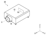
- FIG. 1 is a schematic perspective view of a projector equipped with a lens driving device according to an embodiment of the present disclosure
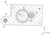
- FIG. 4 is a cross-sectional view showing meshing between a second gear and a third gear
- FIG. 13 is a diagram showing a casing of the position detection unit being biased by a biasing member.
- Front view of the casing of the position detection unit FIG. 2 shows second gear shifted towards third gear
- FIG. 1 is a schematic perspective view of a projector equipped with a lens driving device according to one embodiment of the present disclosure.
- FIG. 2 is a perspective view of the lens driving device.
- FIG. 3 is an exploded perspective view of the lens driving device.
- the X-Y-Z Cartesian coordinate system shown in the figure is intended to facilitate understanding of the embodiments of the present disclosure, and does not limit the embodiments of the present disclosure.
- the X-axis direction is the front-to-back direction of the projector
- the Y-axis direction is the left-to-right direction
- the Z-axis direction is the height direction.
- lens drive device 14 As shown in FIG. 1, projector 10 has a housing 12 and a lens drive device 14 (rotary body drive device) mounted on housing 12. As shown in FIGS. 2 and 3, lens drive device 14 includes a lens barrel 18 equipped with a lens 16, and a lens drive module 20 that shifts lens 16 of lens barrel 18 in the extension direction of its optical axis C (X-axis direction). First, the lens barrel 18 will be described.
- Figure 4 is an exploded perspective view of the lens barrel.
- the lens barrel 18 includes a cylindrical lens support member 22 that supports the lens 16, and a cylindrical barrel body 24 that supports the lens support member 22 so that it can be shifted in the extension direction of the optical axis C (X-axis direction).
- the lens barrel 18 is attached to the housing 12 of the projector 10 via the barrel body 24.
- the lens support member 22 is stored in the barrel body 24 so that it can shift in the extension direction of the optical axis C (X-axis direction).
- a number of guide pins 26 are provided on the outer peripheral surface of the lens support member 22.
- a number of guide holes 24a that guide each of the guide pins 26 are provided in the barrel body 24. The guide holes 24a extend in the extension direction of the optical axis C.
- the lens barrel 18 also includes a cam unit 28 for shifting the lens support member 22 in the extension direction of the optical axis C (the X-axis direction).
- the cam unit 28 is composed of a cylindrical outer cam 30 that is inserted onto the barrel body 24, and an inner cam 32 that is inserted into the barrel body 24 and also inserted onto the lens support member 22.
- the outer cam 30 of the cam unit 28 is supported by the barrel body 24 so as to be rotatable in the circumferential direction of the outer peripheral surface of the barrel body 24.
- a number of guide pins 34 are provided on the inner peripheral surface of the outer cam 30.
- a number of guide holes 24b that guide each of the guide pins 34 are provided in the housing body 24.
- the guide holes 24b extend in the circumferential direction of the outer peripheral surface of the housing body 24.
- the guide pin 34 is fixed to the outer cam 30.
- the guide pin 34 also engages with a number of engagement holes 32a provided in the inner cam 32. This allows the outer cam 30 and the inner cam 32 to be integrated.
- the inner cam 32 of the cam unit 28 is formed with a number of cam grooves 32b that move each of the multiple guide pins 26 provided on the lens support member 22.
- the cam grooves 32b extend in the circumferential direction of the outer circumferential surface of the inner cam 32, while also extending in the extension direction of the optical axis C (X-axis direction).
- the outer cam 30 (rotating body) of the cam unit 28 of the lens barrel 18 is rotated by the lens driving module 20.
- the lens driving module 20 includes a base member 40, a driving gear 42 that rotates the outer cam 30 of the cam unit 28 of the lens barrel 18, and a motor 44 that rotates the driving gear 42.
- the lens driving module 20 is provided on the lens housing 18 by fixing the base member 40 to the housing main body 24 via a fixing screw 46, as shown in Figure 3.
- a reduction mechanism 48 is provided between the driving gear 42 and the motor 44.
- the drive gear 42 is a so-called spur gear, and is rotated by the motor 44 around a rotation center line R0 extending in the extension direction of the optical axis C (X-axis direction).
- the outer cam 30 of the cam unit 28 is formed with external teeth 30a extending in its circumferential direction.
- the external teeth 30a are so-called spur gear-shaped teeth.
- the motor 44 is controlled by a controller 50 provided in the housing 12 of the projector 10 as shown in FIG. 1.
- the controller 50 is, for example, a board on which a circuit, a processor, etc. are provided.
- a position detection unit 60 is provided to adjust the position of the lens 16 in the extension direction (X-axis direction) of the optical axis C.
- the rotation angle position refers to the rotation angle from the reference position.
- Figure 5 is an exploded perspective view of the position detection unit.
- the position detection unit 60 is a part of the lens driving module 20. Specifically, as shown in FIG. 5, the position detection unit 60 includes a base member 40, a casing (rotating member) 62 supported by the base member 40, a first gear 64 supported by the casing 62, and a sensor 66 for detecting the rotational angle position of the first gear 64.
- the casing 62 is composed of a front casing 68 and a rear casing 70.
- the casing 62 is supported by the base member 40 so as to be rotatable about the rotation center line of the outer cam 30, i.e., a first rotation center line R1 that is parallel to the optical axis C.
- the casing 62 (its front casing 68) is formed with a through hole 68a that penetrates in the extension direction of the first rotation center line R1 (X-axis direction), and a support rod 72 is inserted into the through hole 68a.
- One end of the support rod 72 is supported by the base member 40.
- a slit washer 74 that prevents the casing 62 from falling off is attached to the other end of the support rod 72.
- the first gear 64 is supported by the casing 62 so as to be rotatable about a second rotation center line R2 that is parallel to the first rotation center line R1. Also, as shown in FIG. 2, the first gear 64 meshes with the external teeth 30a of the outer cam 30. As a result, when the outer cam 30 rotates about the optical axis C, the first gear 64 rotates about the second rotation center line R2.
- the sensor 66 is a position sensor, such as a rotary encoder, that detects the rotational angle position of the first gear 64.
- the sensor 66 is mounted on a board 76, which is attached to the casing 62.
- the board 76 is provided with a connector 78 for electrically connecting the controller 50 in the housing 12 of the projector 10 and the sensor 66.
- the rotation angle position of the first gear 64 is detected indirectly.
- a second gear 80 and a third gear 82 are provided within the casing 62.
- the second gear 80 is a so-called spur gear.
- the second gear 80 is provided at one end of a shaft 84 that passes through the front casing 68.
- the other end of the shaft 84 is connected to the first gear 64. That is, the first gear 64 and the second gear 80 are connected in the axial direction (X-axis direction) via the shaft 84.
- the shaft 84 is rotatably supported by a bearing 68b that is integrally formed with the front casing 68. In this embodiment, the second gear 80 and the shaft 84 are integrated.
- Figure 6 is a cross-sectional view showing the meshing of the second gear and the third gear.
- the third gear 82 meshes with the second gear 80 inside the casing 62.
- the third gear 82 is a so-called spur gear, and is supported by the casing 62 so as to be rotatable about a third rotation center line R3 that is parallel to the second rotation center line R2.
- the third gear 82 is connected to the sensor 66. The sensor 66 detects the rotation angle position of the third gear 82.
- the first gear 64 is connected to the sensor 66 via the second gear 80 and the third gear 82.
- the rotational angle position of the first gear 64 is indirectly detected.
- the sensor 66 detects the rotational angle position of the third gear 82 and transmits a signal corresponding to the detection result to the controller 50.
- the controller 50 calculates the rotational angle position of the first gear 64 connected to the second gear 80 based on the signal from the sensor 66 and the gear ratio between the second gear 80 and the third gear 82.
- the controller 50 then calculates the rotational angle position of the outer cam 30 based on the calculated rotational angle position of the first gear 64 and the gear ratio between the external teeth 30a of the outer cam 30 and the first gear 64.
- the relationship between the rotation angle position of the outer cam 30 and the position of the lens 16 in the extension direction of the optical axis C (X-axis direction) is fixed, so the position of the lens 16 can be determined from the rotation angle position of the outer cam 30.
- the position detection unit 60 includes a biasing member 86 that biases the casing 62 so that the first gear 64 continues to contact the outer cam 30.
- FIG. 7 shows the casing of the position detection unit being biased by a biasing member.
- the biasing member 86 is a torsion spring.
- the biasing member 86 is arranged so that the support rod 72 passes through its coil portion 86a.
- One end 86b of the biasing member 86 is hooked to the base member 40, and the other end 86c is hooked to the casing 62.
- This biasing member 86 causes the casing 62 to rotate around the first rotation center line R1 toward the outer cam 30, and the first gear 64 continues to contact the external teeth 30a of the outer cam 30.
- the casing 62 is positioned above the outer cam 30, so the weight of the casing 62 causes the first gear 64 to contact the external teeth 30a of the outer cam 30. To maintain this contact, the biasing member 86 continues to bias the casing 62 toward the outer cam 30.
- Such a biasing member 86 can eliminate backlash between the external teeth 30a of the outer cam 30 and the first gear 64. As a result, there is a one-to-one correspondence between the rotational angle position of the outer cam 30 and the contact state between the external teeth 30a and the first gear 64. In other words, there is a one-to-one correspondence between the rotational angle position of the outer cam 30 and the rotational angle position of the first gear 64. As a result, the rotational angle position of the outer cam 30 can be detected with high accuracy via the first gear 64.
- the biasing member 86 biases the first gear 64 toward the external teeth 30a of the outer cam 30 via the casing 62, thereby increasing the torque load acting on the motor 44 that rotates the outer cam 30 (compared to when the first gear 64 is not biased). In this regard, it is preferable for the first gear 64 to contact the external teeth 30a so that an excessive torque load is not applied to the motor 44.
- the casing 62 is arranged relative to the outer cam 30 so that the straight line L1 connecting the first rotational center line R1 and the second rotational center line R2 is perpendicular to the straight line L2 connecting the optical axis C and the second rotational center line R2 when viewed in the extension direction (X-axis direction) of the rotational center line (i.e., the optical axis C) of the outer cam 30, and the first gear 64 is arranged relative to the casing 62.
- the biasing force F1 from the biasing member 86 via the first gear 64 acts on the outer cam 30 toward the optical axis C. Note that in FIG.
- Figure 8 is a front view of the casing of the position detection unit.
- Figure 9 shows the state in which the second gear has shifted toward the third gear.
- a protrusion 68c is provided on the inner surface of the cylindrical bearing 68b of the front casing 68 of the casing 62.
- the cross-sectional shape of the through hole in the bearing 68b is formed into a "D" shape, so that the protrusion 68c is provided on the inner surface of the bearing 68b.
- reaction force F2 is generated from the external teeth 30a toward the first gear 64.
- the reaction force F2 is the same in magnitude as the biasing force F1, and acts in the opposite direction to the biasing force F1.
- the reaction force F2 acting on the first gear 64 causes the shaft 84 connected to the first gear 64 to shift in the direction of the reaction force F2.
- the shaft 84 shifts in a direction S different from the direction of the reaction force F.
- the shaft 84 shifts in a direction approaching the third rotation center line R3.
- the second gear 80 connected to the shaft 84 shifts toward the third gear 82, thereby eliminating backlash between the second gear 80 and the third gear 82 as much as possible. This elimination of backlash is achieved by the existence of a small gap between the inner surface of the bearing 68b and the shaft 84 so that the bearing 68b rotatably supports the shaft 84.
- the third gear 82 is positioned in the direction of the biasing force F1 relative to the second gear 80, such backlash cannot be eliminated.
- the relative positions of the second gear 80 (i.e., the first gear 64) and the third gear 82 with respect to the outer cam 30 are determined so that such backlash can be eliminated.
- the sensor 66 can detect the rotational angle position of the outer cam 30 with high accuracy.
- controller 50 feedback controls the motor 44 based on the rotational angle position of the outer cam 30 detected with high precision, thereby allowing the rotational angle position of the outer cam 30 to be adjusted with high precision. That is, in this embodiment, the position of the lens 16 in the extension direction of the optical axis C (X-axis direction) can be adjusted with high precision.
- the biasing member 86 that biases the first gear 64 in the position detection unit 60 is a torsion spring.
- the biasing member 86 may be a different type from a torsion spring as long as it can rotate the casing 62 that supports the first gear 64 about the first rotation center line R1.
- the first gear 64 is urged toward the external teeth 30a of the outer cam 30 by the urging member 86, thereby maintaining contact between the first gear 64 and the external teeth 30a of the outer cam 30.
- the embodiment of the present disclosure is not limited to this.
- a magnet may be used to maintain contact between the first gear 64 and the external teeth 30a of the outer cam 30.
- contact between the external teeth 30a of the outer cam 30 and the first gear 64 may be maintained by the weight of the casing 62 and the sensor 66 provided on the casing 62.
- the first gear 64 and the sensor 66 are connected via the second gear 80 and the third gear 82.
- the embodiment of the present disclosure is not limited to this. If possible, the first gear 64 may be directly connected to the sensor 66.
- the rotational angle position of the outer cam 30 can be adjusted with high precision by feedback controlling the motor 44 based on the rotational angle position of the outer cam 30 detected with high precision by the position detection unit 60.
- the drive gear 42 that rotates the outer cam 30 is rotated by the motor 44.
- the drive gear 42 may be rotated by a user via a dial knob, for example.
- the projector 10 is provided with a display that presents to the user the position of the lens corresponding to the rotation angle position of the outer cam 30 detected by the position detection unit 60. The user can adjust the lens to the desired position by rotating the dial knob based on the lens position displayed on the display.
- the rotating body whose rotation angle position is detected is the outer cam 30 inside the lens barrel 18 that shifts the lens 16 of the projector 10.
- the rotating body whose rotation angle position is detected may be any rotating body that has external teeth.
- the embodiment of the present disclosure is intended to detect the rotational angle position of a rotating body in a stopped state, it is not necessarily necessary to eliminate backlash between the external teeth of the rotating body and the first gear during rotation. In other words, the embodiment of the present disclosure eliminates backlash between the external teeth of the rotating body and the first gear so that the first gear contacts the external teeth of the rotating body in substantially the same manner even if the rotating body repeatedly stops at a specific rotational angle position.
- the rotating body drive device is, in a broad sense, a rotating body drive device having a rotating body with external teeth, a drive gear that meshes with the external teeth of the rotating body and rotates around a rotation center line parallel to the rotation center line of the rotating body, and a position detection unit that detects the rotation angle position of the rotating body, the position detection unit including a base member, a rotating member supported on the base member so as to be rotatable around a first rotation center line parallel to the rotation center line of the rotating body, a first gear supported on the rotating member so as to be rotatable around a second rotation center line parallel to the first rotation center line and meshing with the external teeth of the rotating body, and a sensor provided on the rotating member for detecting the rotation angle position of the first gear.
- a position sensor unit is, in a broad sense, a position sensor unit that detects the rotational angle position of a rotating body having external teeth, and includes a base member, a rotating member supported by the base member so as to be rotatable about a first rotation center line parallel to the rotation center line of the rotating body, a first gear supported by the rotating member so as to be rotatable about a second rotation center line parallel to the first rotation center line and meshing with the external teeth of the rotating body, and a sensor provided on the rotating member for detecting the rotational angle position of the first gear.
- This disclosure is applicable to devices that rotate rotating bodies.
Landscapes
- Physics & Mathematics (AREA)
- Engineering & Computer Science (AREA)
- General Physics & Mathematics (AREA)
- General Engineering & Computer Science (AREA)
- Optics & Photonics (AREA)
- Mechanical Engineering (AREA)
- Power Engineering (AREA)
- Lens Barrels (AREA)
Priority Applications (2)
| Application Number | Priority Date | Filing Date | Title |
|---|---|---|---|
| JP2025505188A JPWO2024185476A1 (https=) | 2023-03-03 | 2024-02-19 | |
| US19/316,238 US20250389321A1 (en) | 2023-03-03 | 2025-09-02 | Rotational body drive device and position sensor unit used in same |
Applications Claiming Priority (2)
| Application Number | Priority Date | Filing Date | Title |
|---|---|---|---|
| JP2023032848 | 2023-03-03 | ||
| JP2023-032848 | 2023-03-03 |
Related Child Applications (1)
| Application Number | Title | Priority Date | Filing Date |
|---|---|---|---|
| US19/316,238 Continuation US20250389321A1 (en) | 2023-03-03 | 2025-09-02 | Rotational body drive device and position sensor unit used in same |
Publications (1)
| Publication Number | Publication Date |
|---|---|
| WO2024185476A1 true WO2024185476A1 (ja) | 2024-09-12 |
Family
ID=92675107
Family Applications (1)
| Application Number | Title | Priority Date | Filing Date |
|---|---|---|---|
| PCT/JP2024/005731 Ceased WO2024185476A1 (ja) | 2023-03-03 | 2024-02-19 | 回転体駆動装置およびそれに使用される位置センサユニット |
Country Status (3)
| Country | Link |
|---|---|
| US (1) | US20250389321A1 (https=) |
| JP (1) | JPWO2024185476A1 (https=) |
| WO (1) | WO2024185476A1 (https=) |
Citations (5)
| Publication number | Priority date | Publication date | Assignee | Title |
|---|---|---|---|---|
| JPS58152023U (ja) * | 1982-04-06 | 1983-10-12 | ソニー株式会社 | ダイヤル機構 |
| WO2009118898A1 (ja) * | 2008-03-28 | 2009-10-01 | Necディスプレイソリューションズ株式会社 | 組み合わせ歯車、及びレンズ調整機構、電子機器 |
| JP2011039394A (ja) * | 2009-08-17 | 2011-02-24 | Canon Inc | レンズ装置 |
| JP2011053501A (ja) * | 2009-09-03 | 2011-03-17 | Hitachi Metals Ltd | レンズ駆動装置 |
| JP2013203267A (ja) * | 2012-03-28 | 2013-10-07 | Showa Corp | 電動パワーステアリング装置 |
-
2024
- 2024-02-19 JP JP2025505188A patent/JPWO2024185476A1/ja active Pending
- 2024-02-19 WO PCT/JP2024/005731 patent/WO2024185476A1/ja not_active Ceased
-
2025
- 2025-09-02 US US19/316,238 patent/US20250389321A1/en active Pending
Patent Citations (5)
| Publication number | Priority date | Publication date | Assignee | Title |
|---|---|---|---|---|
| JPS58152023U (ja) * | 1982-04-06 | 1983-10-12 | ソニー株式会社 | ダイヤル機構 |
| WO2009118898A1 (ja) * | 2008-03-28 | 2009-10-01 | Necディスプレイソリューションズ株式会社 | 組み合わせ歯車、及びレンズ調整機構、電子機器 |
| JP2011039394A (ja) * | 2009-08-17 | 2011-02-24 | Canon Inc | レンズ装置 |
| JP2011053501A (ja) * | 2009-09-03 | 2011-03-17 | Hitachi Metals Ltd | レンズ駆動装置 |
| JP2013203267A (ja) * | 2012-03-28 | 2013-10-07 | Showa Corp | 電動パワーステアリング装置 |
Also Published As
| Publication number | Publication date |
|---|---|
| US20250389321A1 (en) | 2025-12-25 |
| JPWO2024185476A1 (https=) | 2024-09-12 |
Similar Documents
| Publication | Publication Date | Title |
|---|---|---|
| JP4998898B2 (ja) | 組み合わせ歯車、及びレンズ調整機構、電子機器 | |
| JP2007301092A (ja) | 電子内視鏡のコネクタ装置 | |
| JP2013238760A (ja) | 偏心/傾き調整構造を有する光学機器 | |
| WO2024185476A1 (ja) | 回転体駆動装置およびそれに使用される位置センサユニット | |
| JP5574696B2 (ja) | レンズ鏡筒 | |
| JP2011017803A (ja) | レンズ鏡筒及び撮像装置 | |
| JP2001074126A (ja) | アンチバックラッシュギア | |
| JP2006178332A (ja) | レンズ駆動装置 | |
| JP3440740B2 (ja) | 監視カメラ装置のフォーカス調整機構 | |
| CN215642018U (zh) | 投影物镜装置及投影系统 | |
| JP4566680B2 (ja) | レンズ移動支持装置 | |
| JPH11230749A (ja) | 測量機 | |
| JP5072785B2 (ja) | 撮像装置 | |
| US20250058819A1 (en) | Steering operation input apparatus | |
| US6002532A (en) | Lens barrel | |
| WO2026048740A1 (ja) | 投射型画像表示装置 | |
| JP7500215B2 (ja) | 操作ユニット及び電子機器 | |
| JP2020082796A (ja) | パークロック装置 | |
| JP5461127B2 (ja) | 測量機 | |
| JP2005180959A (ja) | 回転検出装置 | |
| JP2008025814A (ja) | 遊星歯車装置 | |
| US20240085658A1 (en) | Lens barrel, camera comprising same, and rotational position sensing device | |
| JP2006044511A (ja) | ミラー及び角度検出装置 | |
| JP2004318061A (ja) | 光学装置及びレーザセンサ | |
| JP2004108443A (ja) | 回転伝達装置および回転伝達装置を用いた監視カメラ装置 |
Legal Events
| Date | Code | Title | Description |
|---|---|---|---|
| 121 | Ep: the epo has been informed by wipo that ep was designated in this application |
Ref document number: 24766847 Country of ref document: EP Kind code of ref document: A1 |
|
| ENP | Entry into the national phase |
Ref document number: 2025505188 Country of ref document: JP Kind code of ref document: A |
|
| WWE | Wipo information: entry into national phase |
Ref document number: 2025505188 Country of ref document: JP |
|
| NENP | Non-entry into the national phase |
Ref country code: DE |
|
| 122 | Ep: pct application non-entry in european phase |
Ref document number: 24766847 Country of ref document: EP Kind code of ref document: A1 |