WO2024185011A1 - 手乾燥装置 - Google Patents
手乾燥装置 Download PDFInfo
- Publication number
- WO2024185011A1 WO2024185011A1 PCT/JP2023/008353 JP2023008353W WO2024185011A1 WO 2024185011 A1 WO2024185011 A1 WO 2024185011A1 JP 2023008353 W JP2023008353 W JP 2023008353W WO 2024185011 A1 WO2024185011 A1 WO 2024185011A1
- Authority
- WO
- WIPO (PCT)
- Prior art keywords
- air
- threshold value
- hand
- operation frequency
- discharge device
- Prior art date
- Legal status (The legal status is an assumption and is not a legal conclusion. Google has not performed a legal analysis and makes no representation as to the accuracy of the status listed.)
- Ceased
Links
Images




Classifications
-
- A—HUMAN NECESSITIES
- A47—FURNITURE; DOMESTIC ARTICLES OR APPLIANCES; COFFEE MILLS; SPICE MILLS; SUCTION CLEANERS IN GENERAL
- A47K—SANITARY EQUIPMENT; ACCESSORIES THEREFOR, e.g. TOILET ACCESSORIES
- A47K10/00—Body-drying implements; Toilet paper; Holders therefor
- A47K10/48—Drying by means of hot air
Definitions
- This disclosure relates to a hand dryer that dries wet hands.
- a known device for drying wet hands is a hand dryer that sprays a high-velocity airflow onto wet hands to blow away any water adhering to the hands, drying the hands and also purifying the air in the space in which the hand dryer is installed.
- Patent Document 1 discloses a hand dryer that purifies the air in the space in which the hand dryer is installed.
- the hand dryer disclosed in Patent Document 1 is equipped with a roll filter and a deodorizing filter as air purification functional parts that purify the air sucked in from the air intake, and purifies the high-pressure airflow ejected from the hand dryer and purifies the air in the space in which the hand dryer is installed.
- the degree of air pollution in the space in which the hand dryer is installed changes depending on how frequently the hand dryer is used. Therefore, it is desirable to purify the air in the space in which the hand dryer is installed depending on its degree of pollution.
- the hand dryer disclosed in Patent Document 1 purifies the air in the space in which the hand dryer is installed, but has the problem that it is not able to purify the air in the space depending on its degree of pollution.
- the present disclosure has been made in consideration of the above, and aims to provide a hand dryer that can purify the air depending on the degree of air pollution in the installation space.
- the hand dryer includes a hand detection sensor that detects a hand inserted into a hand insertion section, a housing having a first air passage through which air flows and a second air passage through which air flows independent of the first air passage, a first air blower provided inside the first air passage that generates an air flow in the first air passage so that air taken in from outside the housing is blown into the hand insertion section in response to detection of a hand by the hand detection sensor, a discharge device provided inside the second air passage that purifies the air flowing in the second air passage, a second air blower provided inside the second air passage that generates an air flow in the second air passage so that air taken in from outside the housing is discharged to the outside of the housing through the discharge device, and a control unit that calculates the operation frequency at a preset time of the first air blower that operates when the hand detection sensor detects a hand, and controls the start and stop of the operation of the second air blower and the on and off of the discharge device based on the calculated operation frequency.
- the hand dryer disclosed herein has the advantage of being able to purify the air depending on the degree of air pollution in the installation space.
- FIG. 1 is a perspective view showing a hand dryer according to a first embodiment.
- 2 is a cross-sectional view of the hand dryer according to the first embodiment, taken along an XY plane including line II-II shown in FIG. 1 .
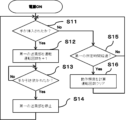
- 4 is a flowchart for determining the operation frequency of the hand dryer according to the first embodiment.
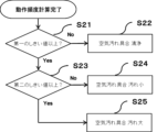
- 5 is a flowchart for determining a degree of contamination of air in an installation space of the hand dryer according to the first embodiment.
- 11 is a flowchart showing the operation of the air purifying unit when the air in the installation space of the hand dryer according to the second embodiment is highly polluted.
- 11 is a flowchart showing the operation of the air purifying unit when the air in the installation space of the hand dryer according to the second embodiment is slightly polluted.
- FIG. 2 is a diagram showing an example of a hardware configuration of a control unit of the hand dryer according to the first and second embodiments.
- the hand dryer 1 according to the embodiment is described in detail below with reference to the drawings.
- FIG. 1 is a perspective view showing a hand dryer 1 according to a first embodiment.
- FIG. 2 is a cross-sectional view of the hand dryer 1 according to the first embodiment, which is a cross-sectional view of the hand dryer 1 cut along an XY plane including a line II-II shown in FIG. 1.
- the X-axis direction is the depth direction or front-rear direction
- the Y-axis direction is the height direction or up-down direction
- the Z-axis direction is the left-right direction or width direction.
- the + side the side of the arrow in FIG.
- the + side (the side of the arrow in FIG. 1) in the Y-axis direction is the upper side or upper surface side
- the - side (the opposite side of the arrow in FIG. 1) is the lower side or lower surface side
- the + side (the side of the arrow in FIG. 1) in the Z-axis direction is the right side or right side side
- the - direction (the opposite side of the arrow in FIG. 1) is the left side or left side side.
- the hand dryer 1 has a box-shaped outer shell formed by a housing 2.
- the housing 2 has a top surface 2a, a front surface 2d, a bottom surface 2b, a back surface 2e, a right side surface 2c, and a left side surface 2f.
- the top surface 2a is formed with a top opening 3c in between, and connects the upper ends of the back surface 2e, the right side surface 2c, and the left side surface 2f.
- the front surface 2d (indicating the surface to which the first front panel 30 and the second front panel 31 are attached) connects the front ends of the top surface 2a, the bottom surface 2b, the right side surface 2c, and the left side surface 2f.
- the bottom surface 2b connects the lower ends of the front surface 2d, the back surface 2e, the right side surface 2c, and the left side surface 2f.
- the back surface 2e connects the rear ends of the top surface 2a, the bottom surface 2b, the right side surface 2c, and the left side surface 2f.
- the right side surface 2c connects the right ends of the top surface 2a, the front surface 2d, the bottom surface 2b, and the back surface 2e.
- the left side surface 2f connects the left ends of the top surface 2a, front surface 2d, bottom surface 2b, and back surface 2e.
- An upper opening 3c is provided on the upper surface 2a of the housing 2.
- the upper opening 3c is provided in the width direction of the housing 2 from the upper end of the right side surface 2c of the housing 2 to the upper end of the left side surface 2f.
- a hand insertion section 3 is provided below the upper opening 3c of the housing 2.
- the hand insertion section 3 has a space that covers the user's hand inserted from the upper opening 3c.
- the hand insertion section 3 is a space surrounded by the front side protrusion 3b, the rear side protrusion 3a, and the water receiving section 5.
- the part sandwiched between the hand insertion section 3 and the front surface 2d of the housing 2 is the front side protrusion 3b.
- the part sandwiched between the hand insertion section 3 and the rear surface 2e of the housing 2 is the rear side protrusion 3a.
- a water receiving section 5 is provided at the bottom of the hand insertion section 3 so as to connect the lower ends of the front side protrusion 3b and the rear side protrusion 3a.
- the hand insertion section 3 has a U-shaped cross section when viewed from the side, and the user's hand is inserted into the space within this U-shaped cross section. Hand insertion section 3 is slightly inclined from the front to the rear as it moves from top to bottom, so that a user standing in front of hand dryer 1 can easily insert their hands.
- side openings 3d are provided on the right side 2c and left side 2f of housing 2, which are connected to top opening 3c and follow a U-shaped cross section. This allows the user to freely insert and remove their hands from hand insertion section 3 from the top, right, and left sides.
- the water receiving portion 5 is provided with a drain outlet (not shown) for draining the water from the water receiving portion 5.
- the upper end of a drainage channel (not shown) that extends vertically within the housing 2 is attached to the drain outlet.
- the lower end of the drainage channel is connected to a drain tank 7 installed at the bottom of the housing 2.
- the drain tank 7 stores the water that is drained through the drainage channel.
- the drain tank 7 is detachably attached to the bottom of the housing 2.
- the drain outlet is sloped to allow the water to flow downward. The water that adheres to the water receiving portion 5 flows through the drainage channel and is stored in the drain tank 7.
- a hand detection sensor 6 that detects a hand inserted into the hand insertion section 3 is provided on the upper side of the rear protrusion 3a on the hand insertion section 3 side.
- the hand detection sensor 6 is provided near the upper opening 3c of the hand insertion section 3.
- the hand detection sensor 6 is provided below the first rear nozzle 4b and the second rear nozzle 4c.
- the hand detection sensor 6 is electrically connected to the control unit 9 by electrical wiring (not shown).
- the output result of the hand detection sensor 6 is sent to the control unit 9.
- the hand detection sensor 6 is, for example, an infrared sensor, but it may be any sensor that can detect a hand inserted into the hand insertion section 3.
- a first rear nozzle 4b and a second rear nozzle 4c are provided on the upper side of the hand insertion section 3 side of the rear protrusion 3a, which spray air to dry the hand inserted into the hand insertion section 3.
- the first rear nozzle 4b and the second rear nozzle 4c are provided near the upper opening 3c of the hand insertion section 3.
- the first rear nozzle 4b and the second rear nozzle 4c are provided above the hand detection sensor 6.
- the first rear nozzle 4b and the second rear nozzle 4c are provided in order from the hand detection sensor 6 toward the upper side.
- a first front nozzle 4a is provided on the upper side of the hand insertion section 3 side of the front protrusion 3b, which sprays air to dry the hand inserted into the hand insertion section 3.
- the first front nozzle 4a is provided near the upper opening 3c of the hand insertion section 3.
- the first front nozzle 4a, the first rear nozzle 4b, and the second rear nozzle 4c are each formed of a plurality of small holes that open diagonally downward.
- the multiple small holes of the first front nozzle 4a, the first rear nozzle 4b, and the second rear nozzle 4c are arranged at preset intervals in the width direction of the housing 2.
- the first rear nozzle 4b and the second rear nozzle 4c are shown above the hand insertion section 3 of the rear protrusion 3a, but the number is not particularly limited, and for example, only the first rear nozzle 4b may be used.
- the first front nozzle 4a, the first rear nozzle 4b, and the second rear nozzle 4c are collectively referred to simply as nozzle 4.
- a first air passage 25 which is an air passage through which air flows, and a second air passage 26 that is independent of the first air passage 25 are formed.
- the air flowing in the first air passage 25 is indicated by a solid arrow A
- the air flowing in the second air passage 26 is indicated by a dashed arrow B.
- the first air passage 25 is an air passage that generates an air flow from the first intake port 10 toward the nozzle 4.
- the first air passage 25 extends in the vertical direction of the housing 2.
- the first air passage 25 has a first intake air passage 25a that runs from the first intake port 10 to the intake side of the first blower 14, a first front exhaust air passage 25c that branches off at the exhaust side of the first blower 14 and runs to the first front nozzle 4a, and a first rear exhaust air passage 25b that runs to the first rear nozzle 4b and the second rear nozzle 4c.
- the first intake air passage 25a is an air passage that takes in air from outside the housing 2 through the first intake port 10 into the housing 2 and supplies it to the first blower 14.
- the first front exhaust air passage 25c is an air passage that exhausts the air flow generated by the first blower 14 toward the first front nozzle 4a.
- the first rear exhaust air passage 25b is an air passage that exhausts the air flow generated by the first blower 14 toward the first rear nozzle 4b and the second rear nozzle 4c.
- the first front exhaust air passage 25c is formed mainly inside the front protrusion 3b and extends in the vertical direction.
- the first rear exhaust air passage 25b is formed mainly inside the rear protrusion 3a and extends in the vertical direction.
- a heater 27 that heats the air flow is installed at the branch point of the first front exhaust air passage 25c and the first rear exhaust air passage 25b.
- the first air intake 10 is provided on the bottom surface 2b of the housing 2.
- the first air intake 10 is provided on the bottom surface 2b near the rear surface 2e.
- a first air intake filter 15 is attached to the first air intake 10.
- the first air intake filter 15 collects impurities contained in the air sucked in from the first air intake 10.
- the impurities include, for example, dust, dirt, bacteria, and viruses.
- a HEPA (High Efficiency Particulate Air) filter which has a high ability to remove impurities, is used as the first air intake filter 15.
- the first blower 14 is provided inside the first air passage 25.
- the first blower 14 is, for example, an axial fan.
- the first blower 14 pressurizes the air taken in from the first intake port 10 into the first intake air passage 25a, and ejects the high-pressure air from the nozzle 4 through the first front exhaust air passage 25c and the first rear exhaust air passage 25b.
- the first blower 14 is provided almost in the center of the housing 2, below the hand insertion section 3.
- the first blower 14 has a first motor 14a and a first blade 14b attached to the rotating shaft of the first motor 14a and rotated by the first motor 14a.
- the first motor 14a and the first blade 14b are installed in the X-axis direction toward which the central axis of the first motor 14a faces.
- the first motor 14a is installed on the front 2d side, and the first blade 14b is installed on the rear 2e side.
- the operation of the first blower 14 is controlled by the control unit 9.
- the control section 9 operates the first blower section 14.
- air is taken into the housing 2 from the first intake port 10 through the first intake filter 15.
- the air taken into the housing 2 is made high-pressure air by the first blower section 14 through the first intake air passage 25a.
- the air made high-pressure by the first blower section 14 is heated by the heater 27, and the high-pressure air is blown from the nozzle 4 through the first front exhaust air passage 25c and the first rear exhaust air passage 25b toward the hand inserted into the hand insertion section 3 by the user.
- This blows off water on the user's hand, drying the hand.
- the water blown off the user's hand flows through the drainage passage from the drain outlet provided in the water receiving section 5 and is stored in the drain tank 7.
- the second air passage 26 is an air passage that generates an air flow from the second air intake 11 toward the exhaust port 12.
- the air purifier 17 is provided inside the second air passage 26.
- the air purifier 17 purifies the air taken in from the second air intake 11 and exhausts the purified air from the exhaust port 12.
- the second air passage 26 has a second air intake passage 26a that runs from the second air intake 11 to the air purifier 17, and a second air exhaust passage 26b that runs from the air purifier 17 to the exhaust port 12.
- the second air intake passage 26a extends in the left-right direction so as to connect the second air intakes 11 provided on the left and right sides of the housing 2.
- the second air intake passage 26a is an air passage that takes in air from outside the housing 2 from the second air intake 11 into the housing 2 and supplies it to the second blower 16 of the air purifier 17.
- the second exhaust air duct 26b is an air duct that exhausts the air generated by the second blower 16 and flowing through the discharge device 18 and the deodorizing filter 20 to the outside of the housing 2 from the exhaust port 12.
- the second exhaust air duct 26b extends in the vertical direction of the housing 2.
- the second air intake 11 has a vertically long shape and is provided on the right side 2c and left side 2f of the housing 2.
- the second air intake 11 is provided on the right side 2c and left side 2f, closer to the front 2d.
- the second air intake 11 is provided closer to the bottom surface 2b in the height direction.
- the second air intake 11 is provided lower than the hand insertion section 3.
- a second air intake filter 19 is attached to the second air intake 11.
- the second air intake filter 19 collects impurities contained in the air sucked in from the second air intake 11.
- the impurities include, for example, dust, dirt, bacteria, and viruses.
- the second intake filter 19 is, for example, a HEPA (High Efficiency Particulate Air) filter, which has a high ability to remove impurities.
- HEPA High Efficiency Particulate Air
- the air purifier 17 purifies the air from the second air intake 11 and exhausts the purified air from the exhaust 12.
- the air purifier 17 is provided inside the housing 2 below the hand insertion section 3 and the first air blower 14.
- the air purifier 17 has a second air blower 16 and a discharge device 18.
- the air purifier 17 may also have a deodorizing filter 20.
- the second air blower 16 is provided on the second air intake 11 side.
- the deodorizing filter 20 is provided on the exhaust 12 side.
- the discharge device 18 is provided between the second air blower 16 and the deodorizing filter 20.
- the second blower 16 is provided inside the second air passage 26.
- the second blower 16 is, for example, a sirocco fan.
- the second blower 16 takes in air from the second air intake 11 into the second air intake duct 26a and generates an air flow toward the exhaust port 12.
- the second blower 16 is provided below the first blower 14 at approximately the same height as the second air intake 11.
- the second blower 16 has a second motor 16a and a second blade 16b attached to the rotating shaft of the second motor 16a and rotated by the second motor 16a.
- the second motor 16a and the second blade 16b are installed in the X-axis direction toward which the central axis of the second motor 16a faces.
- the second motor 16a is installed on the rear surface 2e side, and the second blade 16b is installed on the front surface 2d side.
- the operation of the second blower 16 is controlled by the control unit 9.
- the operating modes of the second blower 16 include low operation, high operation, and stopped.
- the discharge device 18 is disposed below the second blower 16 (downstream of the second intake air duct 26a).
- the discharge device 18 is composed of a discharge electrode and a counter electrode.
- the discharge device 18 generates a discharge space by turning on the discharge device 18 and applying a voltage between the discharge electrode and the counter electrode that constitute the discharge device 18.
- the air is purified by removing or inactivating viruses, bacteria, mold, and allergens that pass through this discharge space.
- the operation of the discharge device 18 is controlled by the control unit 9.
- the control unit 9 operates the discharge device 18 by turning on the discharge device 18, for example, by turning on the power supply of the discharge device 18.
- the control unit 9 also stops the operation of the discharge device 18 by turning off the discharge device 18, for example, by turning off the power supply of the discharge device 18.
- the deodorizing filter 20 is provided closer to the exhaust port 12 than the discharge device 18.
- the deodorizing filter 20 is made of a porous material such as activated carbon.
- the deodorizing filter 20 adsorbs odor molecules contained in the air by passing the air through the porous material such as activated carbon contained in the deodorizing filter 20.
- the exhaust port 12 is provided on the bottom surface 2b of the housing 2.
- the exhaust port 12 is provided on the bottom surface 2b, close to the front surface 2d.
- the control unit 9 controls the operation of the air purifier 17. More specifically, it controls the operation of the second blower 16 and the discharge device 18 that constitute the air purifier 17.
- air is taken into the housing 2 from the second air intake 11 through the second air intake filter 19.
- the air taken into the housing 2 is sent to the discharge device 18 and the deodorizing filter 20 by the second blower 16 through the second air intake duct 26a.
- the discharge device 18 operates in conjunction with the operation of the second blower 16.
- the air purified by the discharge device 18 and the deodorizing filter 20 is exhausted to the outside of the housing 2 from the exhaust duct 12 through the second exhaust duct 26b.
- the clean air exhausted to the outside of the housing 2 from the exhaust duct 12 cleans the space in which the hand dryer 1 is installed.
- the operation of the air purifier 17 is linked to the operation of the first blower 14.
- the top surface 2a, front surface 2d, bottom surface 2b, back surface 2e, right side surface 2c, and left side surface 2f that form the box-shaped outer shell of the housing 2 are each formed of a panel.
- the front surface 2d is formed of a first front panel 30 provided on the upper side in the height direction and a second front panel 31 provided on the lower side in the height direction.
- the second front panel 31 is easily removable for maintenance of the air purifier 17.
- the other surfaces, the top surface 2a, bottom surface 2b, back surface 2e, right side surface 2c, and left side surface 2f, are also similarly formed of panels.
- the panels are, for example, decorative panels.
- the back surface 2e that faces the wall of the installation space of the hand dryer 1 may not use a panel or may use a panel only in part.
- FIG. 3 is a flowchart for determining the operation frequency of the hand dryer 1 according to the first embodiment.
- step S11 the control unit 9 determines whether or not the user's hand has been inserted into the hand insertion section 3.
- the fact that the user's hand has been inserted into the hand insertion section 3 can be determined by a detection signal (e.g., Hi "signal present") from the hand detection sensor 6. If the control unit 9 determines that the user's hand has been inserted into the hand insertion section 3 (Yes in step S11), it proceeds to step S12. On the other hand, if the control unit 9 determines that the user's hand has not been inserted into the hand insertion section 3 (No in step S11), it proceeds to step S15, which will be described later.
- a detection signal e.g., Hi "signal present
- step S12 the control unit 9 operates the first blower 14 and counts up the number of times the first blower 14 has been operated.
- the operation of the first blower 14 can be determined, for example, by detecting whether or not electricity is being applied to the first motor 14a of the first blower 14. Then, the process proceeds to step S13.
- step S13 the control unit 9 determines whether or not the user's hand has been removed from the hand insertion unit 3.
- the fact that the user's hand has been removed from the hand insertion unit 3 can be detected by a detection signal (e.g., Lo "no signal") from the hand detection sensor 6. If the control unit 9 determines that the user's hand has not been removed from the hand insertion unit 3 (No in step S13), it continues to determine whether or not the user's hand has been removed from the hand insertion unit 3 in step S13. On the other hand, if the control unit 9 determines that the user's hand has been removed from the hand insertion unit 3 (Yes in step S13), it proceeds to step S14.
- a detection signal e.g., Lo "no signal
- step S14 the control unit 9 stops the operation of the first blower unit 14. Then, the process returns to step S11.
- step S11 if the control unit 9 determines that the user's hand is not inserted into the hand insertion unit 3 (No in step S11), the control unit 9 proceeds to step S15.
- step S15 the control unit 9 determines whether a preset time (referred to as the first predetermined time) has elapsed.
- the first predetermined time is set as a sampling time for calculating the operation frequency of the first air blowing unit 14.
- the first predetermined time is set to, for example, 30 minutes. If the first predetermined time has not elapsed (No in step S15), the control unit 9 returns to step S11. On the other hand, if the first predetermined time has elapsed (Yes in step S15), the control unit 9 proceeds to step S16.
- step S16 the control unit 9 calculates the operation frequency of the first blower unit 14 and then clears, i.e. resets, the number of operations.
- the operation frequency may be the number of operations per unit time. In this embodiment, the operation frequency is the number of operations per hour. For example, if the first specified time is 30 minutes, the operation frequency is the number of operations x 2 (times/hour).
- Figure 4 is a flowchart for determining the degree of contamination of the air in the installation space of the hand dryer 1.
- step S21 the control unit 9 determines whether the operation frequency of the first air blowing unit 14 calculated in step S16 is equal to or greater than a first threshold value.
- the first threshold value is a threshold value for determining that there are few users in the installation space of the hand dryer 1, i.e., that the population density is low.
- the first threshold value is set to, for example, 10 (times/hour). If the operation frequency is less than the first threshold value (No in step S21), the control unit 9 determines that the air is clean, i.e., there is no contamination, and proceeds to step S22. If the operation frequency is equal to or greater than the first threshold value (Yes in step S21), the control unit 9 proceeds to step S23.
- step S23 the control unit 9 determines whether the operation frequency of the first air blowing unit 14 calculated in step S16 is equal to or greater than a second threshold value.
- the second threshold value is a threshold value for determining whether there are many users in the installation space of the hand dryer 1, i.e., whether the population density is high.
- the second threshold value is set, for example, to 30 (times/hour). If the operation frequency is less than the second threshold value (No in step S23), the control unit 9 determines that the air is not very polluted, and proceeds to step S24. If the operation frequency is equal to or greater than the second threshold value (Yes in step S23), the control unit 9 determines that the air is very polluted, and proceeds to step S25.
- the control unit 9 controls the air purification unit 17 as follows in each of the above-mentioned steps S22, S24, and S25.
- step S22 where it is determined that the degree of dirt is clean, the control unit 9 stops the operation of the second blower 16 and turns off the discharge device 18.
- step S24 where it is determined that the degree of dirt is low, the control unit 9 operates the second blower 16 at low power and turns on the discharge device 18.
- step S25 where it is determined that the degree of dirt is high, the control unit 9 operates the second blower 16 at high power and turns on the discharge device 18.
- the hand dryer 1 As described above, the hand dryer 1 according to the first embodiment is provided in the housing 2 with the first air passage 25 having the first blower 14 that sprays air onto the hand inserted in the hand insertion section 3, and the second air passage 26 having the discharge device 18 that purifies the air and the second blower 16 that exhausts the purified air through the discharge device 18 to the outside of the housing 2, independent of the first air passage 25.
- the control unit 9 calculates the operation frequency of the first blower 14 during a preset time period when the hand detection sensor 6 detects the hand inserted in the hand insertion section 3, and when it is determined that the air in the installation space of the hand dryer 1 is dirty according to the calculated operation frequency, the control unit 9 turns on the discharge device 18 that purifies the air and starts the operation of the second blower 16. Therefore, the air in the installation space can be properly purified according to the degree of dirtiness of the air in the installation space of the hand dryer 1.
- the second blower unit 16 is described as having three operating patterns, namely, stopped, weak operation, and strong operation, corresponding to three levels of air pollution, namely, clean, slightly dirty, and very dirty.
- this is not limited to the description, and the number of stages for determining pollution and the operating patterns of the second blower unit 16 may be increased. This makes it possible to more accurately adjust the air volume during operation of the second blower unit 16 and turn the discharge device 18 on and off according to the level of air pollution, thereby more appropriately purifying the air in the installation space of the hand dryer 1. This further contributes to energy savings in the hand dryer 1.
- the first predetermined time which is the sampling time for calculating the operation frequency, may be set by the user. For example, shortening the sampling time can improve tracking ability. On the other hand, extending the sampling time can improve the accuracy of determining the degree of air pollution.
- the first and second thresholds for judging the degree of air contamination may be set by the user. For example, when a person exercising in a gymnasium or the like uses hand dryer 1, the user's breathing becomes rough, and it is expected that the air in the installation space of hand dryer 1 will become dirty even if the frequency of use is lower than normal. Therefore, by allowing the user to arbitrarily set the thresholds according to the installation space of hand dryer 1, control that matches the usage environment becomes possible.
- Embodiment 2 ⁇ Operation of hand dryer 1>
- the control of air purifying unit 17 after it is determined that the air is slightly or highly polluted is different from that in the first embodiment.
- the control of second blower unit 16 and discharge device 18 after it is determined that the air is slightly or highly polluted is subdivided. Note that the configuration of hand dryer 1 in the second embodiment is the same as that of hand dryer 1 in the first embodiment, and therefore a description thereof will be omitted here.
- FIG. 5 is a flowchart showing the operation of the air purifying unit 17 when the air in the installation space of the hand dryer 1 according to the second embodiment is highly polluted.
- the flowchart in FIG. 5 shows the process from when the air in the installation space is determined to be highly polluted in step S25 in FIG. 4 until the next air pollution level is determined.
- step S31 the control unit 9 operates the second blower 16 at high speed and turns on the discharge device 18.
- the operation of step S31 is the same as the operation of step S25 shown in FIG. 4 of the first embodiment.
- step S32 the control unit 9 determines whether the operation frequency of the first blower unit 14 calculated in step S16 is equal to or greater than the third threshold value. In step S32, if the operation frequency is less than the third threshold value (No in step S32), the control unit 9 proceeds to step S33.
- step S33 the control unit 9 determines whether a preset time (referred to as the second predetermined time) has elapsed. If the second predetermined time has not elapsed (No in step S33), the control unit 9 continues the determination until the second predetermined time has elapsed. If the second predetermined time has elapsed (Yes in step S33), the control unit 9 proceeds to step S34.
- a preset time referred to as the second predetermined time
- step S34 the control unit 9 operates the second blower unit 16 at low speed, and then proceeds to step S38.
- the third threshold value is a threshold value for determining the degree of dirtiness based on the operating frequency of the first air blowing unit 14.
- the third threshold value is a threshold value for determining that the air is relatively less dirty, among the air states determined to be highly dirty in step S25 of FIG. 4.
- the third threshold value is set, for example, to 40 (times/hour).
- the second specified time is the time it takes to purify the air from a relatively less dirty state among the highly dirty air states.
- the second specified time is set, for example, to 10 minutes.
- step S32 if the value is equal to or greater than the third threshold value (Yes in step S32), the control unit 9 proceeds to step S35.
- step S35 the control unit 9 determines whether the operation frequency of the first blower unit 14 calculated in step S16 is equal to or greater than the fourth threshold value. If it is less than the fourth threshold value (No in step S35), the process proceeds to step S36.
- step S36 the control unit 9 determines whether a preset time (referred to as the third specified time) has elapsed. If the third specified time has not elapsed (No in step S36), the control unit 9 continues the determination until the third specified time has elapsed. If the third specified time has elapsed (Yes in step S36), the control unit 9 proceeds to step S37.
- a preset time referred to as the third specified time
- step S37 the control unit 9 operates the second blower unit 16 at low speed, and then proceeds to step S38.
- the fourth threshold value is a threshold value for determining the degree of dirtiness based on the operating frequency of the first air blowing unit 14.
- the fourth threshold value is a threshold value for determining whether the air is highly polluted or not when it is determined in step S32 that the air is highly polluted.
- the fourth threshold value is set to, for example, 60 (times/hour).
- the third specified time is the time it takes to purify the air from a state of moderate dirtiness when the air is highly polluted.
- the third specified time is longer than the second specified time, and is set to, for example, 20 minutes.
- FIG. 6 is a flowchart explaining the operation of the air purifier 17 when the air in the installation space of the hand dryer 1 according to the second embodiment is slightly dirty.
- the flowchart in FIG. 5 shows the process from when the air in the installation space is determined to be slightly dirty in step S24 in FIG. 4 until the next air pollution level is determined.
- step S41 the control unit 9 operates the second blower 16 at low power and turns on the discharge device 18.
- the operation of step S41 is the same as the operation of step S24 shown in FIG. 4 of the first embodiment.
- step S42 the control unit 9 determines whether the operation frequency of the first blower unit 14 calculated in step S16 is equal to or greater than a fifth threshold value. In step S42, if the operation frequency is less than the fifth threshold value (No in step S42), the control unit 9 proceeds to step S43.
- step S43 the control unit 9 determines whether a preset time (referred to as the fourth predetermined time) has elapsed. If the fourth predetermined time has not elapsed (No in step S43), the control unit 9 continues to make the determination until the fourth predetermined time has elapsed. If the fourth predetermined time has elapsed (Yes in step S43), the control unit 9 proceeds to step S44.
- a preset time referred to as the fourth predetermined time
- step S44 the control unit 9 stops the second blower 16 and turns off the discharge device 18, and then proceeds to step S48.
- the fifth threshold value is a threshold value for judging the degree of dirtiness based on the operating frequency of the first air blowing unit 14.
- the fifth threshold value is a threshold value for judging that the air is relatively less dirty, among the air levels judged to be very or very dirty in step S24 of FIG. 4.
- the fifth threshold value is set, for example, to 15 (times/hour).
- the fourth specified time is the time it takes to purify the air from a relatively less dirty state, among the air levels where the air is slightly dirty.
- the fourth specified time is set, for example, to 10 minutes.
- step S42 if the value is equal to or greater than the fifth threshold (Yes in step S42), the control unit 9 proceeds to step S45.
- step S45 the control unit 9 determines whether the operation frequency of the first blower unit 14 calculated in step S16 is equal to or greater than a sixth threshold value. If it is less than the sixth threshold value (No in step S45), the process proceeds to step S46.
- step S46 the control unit 9 determines whether a preset time (referred to as the fifth predetermined time) has elapsed. If the fifth predetermined time has not elapsed (No in step S46), the control unit 9 continues to make the determination until the fifth predetermined time has elapsed. If the fifth predetermined time has elapsed (Yes in step S46), the control unit 9 proceeds to step S47.
- a preset time referred to as the fifth predetermined time
- step S47 the control unit 9 stops the second blower 16 and turns off the discharge device 18, and then proceeds to step S48.
- the sixth threshold value is a threshold value for determining the degree of dirtiness based on the operating frequency of the first air blowing unit 14.
- the sixth threshold value is a threshold value for determining whether the air is highly polluted or not when it is determined in step S42 that the air is highly polluted.
- the sixth threshold value is set, for example, to 20 (times/hour).
- the fifth specified time is the time it takes to purify the air from a state of moderate dirtiness among the states of light air pollution.
- the fifth specified time is longer than the fourth specified time, and is set, for example, to 20 minutes.
- step S48 if the air pollution level is equal to or above the sixth threshold (Yes in step S45) or after steps S44 and S47 have been executed, the control unit 9 causes the air purification unit 17 to continue the set operation until the next time the air pollution level is determined. Specifically, if the air pollution level is equal to or above the sixth threshold (Yes in step S35), the second blower unit 16 continues to operate at low power and the discharge device 18 continues to be turned on. On the other hand, after steps S44 and S47 have been executed, the second blower unit 16 stops operating and the discharge device 18 continues to be turned off.
- the control unit 9 when the air in the installation space of the hand dryer 1 is determined to be dirty based on the operation frequency of the first blower 14, the control unit 9 further subdivides the determination of the air dirtiness based on the operation frequency of the first blower 14, and controls the start and stop of the operation of the second blower 16 and the on and off of the discharge device 18 according to this subdivided determination. In this way, in addition to the effects shown in the first embodiment, the air purifying unit 17 is not operated more than necessary, so that the power consumption of the hand dryer 1 can be suppressed.
- the operation of the air purifier 17 when the air in the installation space of the hand dryer 1 shown in FIG. 5 is highly polluted, and the operation of the air purifier 17 when the air in the installation space of the hand dryer 1 shown in FIG. 6 is less polluted are both performed, but the operation of the air purifier 17 shown in FIG. 5 and the operation of the air purifier 17 shown in FIG. 6 may be performed separately, and an effect equivalent to that shown in the second embodiment can be obtained.
- FIG. 7 is a diagram showing an example of the hardware configuration of the control unit 9 of the hand dryer 1 according to the first and second embodiments.
- FIG. 7 shows a hardware configuration in the case where the functions of the control unit 9 described in the first and second embodiments are realized by using hardware that executes a program.
- the control unit 9 described in the first and second embodiments has a processor 91 that executes various processes, a memory 92 that is a main memory, and a storage device 93 that stores information.
- the processor 91 may be a calculation means such as an arithmetic unit, a microprocessor, a microcomputer, a CPU (Central Processing Unit), or a DSP (Digital Signal Processor).
- the memory 92 may be a non-volatile or volatile semiconductor memory such as a RAM (Random Access Memory), a ROM (Read Only Memory), a flash memory, an EPROM (Erasable Programmable Read Only Memory), or an EEPROM (registered trademark) (Electrically Erasable Programmable Read Only Memory).
- the storage device 93 stores a program for executing a control command that performs the processing of the flowcharts in Figures 3 to 6.
- the processor 91 reads the program stored in the storage device 93 into the memory 92 and executes it.
- the processor 91 reads the program stored in the storage device 93 into the memory 92 and executes it, thereby realizing the functions of the control unit 9 described in the first and second embodiments.
- 1 hand dryer 2 housing, 2a top surface, 2b bottom surface, 2c right side surface, 2d front surface, 2e rear surface, 2f left side surface, 3 hand insertion portion, 3a rear side protrusion portion, 3b front side protrusion portion, 3c top surface opening, 3d side surface opening, 4 nozzle, 4a first front nozzle, 4b first rear nozzle, 4c second rear nozzle, 5 water receiving portion, 6 hand detection sensor, 7 drain tank, 9 control portion, 10 first air intake port, 11 second air intake port, 12 exhaust port, 14 first air blowing portion, 14a first motor, 14b first blade, 15 first air intake filter, 16 second air blowing portion, 16a second motor, 16b second blade, 17 air purifying portion, 18 discharge device, 19 second air intake filter, 20 deodorizing filter, 25 first air duct, 25a First intake air duct, 25b first rear exhaust air duct, 25c first front exhaust air duct, 26 second air duct, 26a second intake air duct, 26b second exhaust air duct, 27 heater, 30 first
Landscapes
- Health & Medical Sciences (AREA)
- Public Health (AREA)
- Filtering Of Dispersed Particles In Gases (AREA)
Priority Applications (2)
| Application Number | Priority Date | Filing Date | Title |
|---|---|---|---|
| PCT/JP2023/008353 WO2024185011A1 (ja) | 2023-03-06 | 2023-03-06 | 手乾燥装置 |
| JP2025504943A JPWO2024185011A1 (https=) | 2023-03-06 | 2023-03-06 |
Applications Claiming Priority (1)
| Application Number | Priority Date | Filing Date | Title |
|---|---|---|---|
| PCT/JP2023/008353 WO2024185011A1 (ja) | 2023-03-06 | 2023-03-06 | 手乾燥装置 |
Publications (1)
| Publication Number | Publication Date |
|---|---|
| WO2024185011A1 true WO2024185011A1 (ja) | 2024-09-12 |
Family
ID=92674283
Family Applications (1)
| Application Number | Title | Priority Date | Filing Date |
|---|---|---|---|
| PCT/JP2023/008353 Ceased WO2024185011A1 (ja) | 2023-03-06 | 2023-03-06 | 手乾燥装置 |
Country Status (2)
| Country | Link |
|---|---|
| JP (1) | JPWO2024185011A1 (https=) |
| WO (1) | WO2024185011A1 (https=) |
Citations (5)
| Publication number | Priority date | Publication date | Assignee | Title |
|---|---|---|---|---|
| JP2002306370A (ja) * | 2001-04-17 | 2002-10-22 | Mitsubishi Electric Corp | 手乾燥装置及び空気清浄器 |
| JP2010075602A (ja) * | 2008-09-29 | 2010-04-08 | Mitsubishi Electric Corp | 手乾燥装置 |
| JP2018064676A (ja) * | 2016-10-17 | 2018-04-26 | 高橋金属株式会社 | 洗浄装置 |
| WO2022091470A1 (ja) * | 2020-10-28 | 2022-05-05 | 三菱電機株式会社 | 手乾燥装置及び手乾燥システム |
| WO2022180694A1 (ja) * | 2021-02-24 | 2022-09-01 | 三菱電機株式会社 | 手乾燥装置 |
-
2023
- 2023-03-06 JP JP2025504943A patent/JPWO2024185011A1/ja active Pending
- 2023-03-06 WO PCT/JP2023/008353 patent/WO2024185011A1/ja not_active Ceased
Patent Citations (5)
| Publication number | Priority date | Publication date | Assignee | Title |
|---|---|---|---|---|
| JP2002306370A (ja) * | 2001-04-17 | 2002-10-22 | Mitsubishi Electric Corp | 手乾燥装置及び空気清浄器 |
| JP2010075602A (ja) * | 2008-09-29 | 2010-04-08 | Mitsubishi Electric Corp | 手乾燥装置 |
| JP2018064676A (ja) * | 2016-10-17 | 2018-04-26 | 高橋金属株式会社 | 洗浄装置 |
| WO2022091470A1 (ja) * | 2020-10-28 | 2022-05-05 | 三菱電機株式会社 | 手乾燥装置及び手乾燥システム |
| WO2022180694A1 (ja) * | 2021-02-24 | 2022-09-01 | 三菱電機株式会社 | 手乾燥装置 |
Also Published As
| Publication number | Publication date |
|---|---|
| JPWO2024185011A1 (https=) | 2024-09-12 |
Similar Documents
| Publication | Publication Date | Title |
|---|---|---|
| EP1602766B1 (en) | Washing machine deodorising unit and control method | |
| JP2012097955A (ja) | 空気清浄装置 | |
| JP6515461B2 (ja) | 衛生洗浄装置 | |
| KR20100089605A (ko) | 공기 청정기의 필터의 교환 시기 산정 방법 | |
| JP5904423B2 (ja) | 衛生洗浄装置 | |
| JP3403723B1 (ja) | 空気調節装置 | |
| JP6367445B2 (ja) | 加湿空気清浄機 | |
| JP2005016841A (ja) | 空気清浄機 | |
| JP2008167900A (ja) | 空気清浄装置 | |
| JP2910627B2 (ja) | 空気清浄機 | |
| JP4055370B2 (ja) | 手乾燥装置及び空気清浄器 | |
| WO2024185011A1 (ja) | 手乾燥装置 | |
| JP2013070791A (ja) | 空気清浄機 | |
| JP6421929B2 (ja) | 便座装置 | |
| JP2005106363A (ja) | 加湿機能付き水フィルター形空気清浄機 | |
| TWI799914B (zh) | 手乾燥裝置 | |
| JP5904422B2 (ja) | 衛生洗浄装置 | |
| JP6424512B2 (ja) | 衛生洗浄装置 | |
| KR20140073328A (ko) | 건조 덕트부와 탈취부의 일체형 구조 및 이를 구비하는 비데 | |
| JP4931890B2 (ja) | 手乾燥装置 | |
| KR20190128285A (ko) | 공기청정기 | |
| JP7069928B2 (ja) | 衛生洗浄装置 | |
| JP2016020781A (ja) | 電気機器 | |
| JP5842149B2 (ja) | 衛生洗浄装置 | |
| JP7205140B2 (ja) | 衛生洗浄装置 |
Legal Events
| Date | Code | Title | Description |
|---|---|---|---|
| 121 | Ep: the epo has been informed by wipo that ep was designated in this application |
Ref document number: 23926225 Country of ref document: EP Kind code of ref document: A1 |
|
| ENP | Entry into the national phase |
Ref document number: 2025504943 Country of ref document: JP Kind code of ref document: A |
|
| WWE | Wipo information: entry into national phase |
Ref document number: 2025504943 Country of ref document: JP |
|
| NENP | Non-entry into the national phase |
Ref country code: DE |
|
| 122 | Ep: pct application non-entry in european phase |
Ref document number: 23926225 Country of ref document: EP Kind code of ref document: A1 |