WO2024176335A1 - 紙幣搬送装置、紙幣搬送方法及び紙幣搬送プログラム - Google Patents
紙幣搬送装置、紙幣搬送方法及び紙幣搬送プログラム Download PDFInfo
- Publication number
- WO2024176335A1 WO2024176335A1 PCT/JP2023/006180 JP2023006180W WO2024176335A1 WO 2024176335 A1 WO2024176335 A1 WO 2024176335A1 JP 2023006180 W JP2023006180 W JP 2023006180W WO 2024176335 A1 WO2024176335 A1 WO 2024176335A1
- Authority
- WO
- WIPO (PCT)
- Prior art keywords
- transport
- sensor
- log
- sensors
- banknote
- Prior art date
- Legal status (The legal status is an assumption and is not a legal conclusion. Google has not performed a legal analysis and makes no representation as to the accuracy of the status listed.)
- Ceased
Links
Images







Classifications
-
- G—PHYSICS
- G07—CHECKING-DEVICES
- G07D—HANDLING OF COINS OR VALUABLE PAPERS, e.g. TESTING, SORTING BY DENOMINATIONS, COUNTING, DISPENSING, CHANGING OR DEPOSITING
- G07D11/00—Devices accepting coins; Devices accepting, dispensing, sorting or counting valuable papers
- G07D11/20—Controlling or monitoring the operation of devices; Data handling
- G07D11/22—Means for sensing or detection
- G07D11/235—Means for sensing or detection for monitoring or indicating operating conditions; for detecting malfunctions
-
- B—PERFORMING OPERATIONS; TRANSPORTING
- B65—CONVEYING; PACKING; STORING; HANDLING THIN OR FILAMENTARY MATERIAL
- B65H—HANDLING THIN OR FILAMENTARY MATERIAL, e.g. SHEETS, WEBS, CABLES
- B65H7/00—Controlling article feeding, separating, pile-advancing, or associated apparatus, to take account of incorrect feeding, absence of articles, or presence of faulty articles
- B65H7/02—Controlling article feeding, separating, pile-advancing, or associated apparatus, to take account of incorrect feeding, absence of articles, or presence of faulty articles by feelers or detectors
-
- G—PHYSICS
- G07—CHECKING-DEVICES
- G07D—HANDLING OF COINS OR VALUABLE PAPERS, e.g. TESTING, SORTING BY DENOMINATIONS, COUNTING, DISPENSING, CHANGING OR DEPOSITING
- G07D11/00—Devices accepting coins; Devices accepting, dispensing, sorting or counting valuable papers
- G07D11/20—Controlling or monitoring the operation of devices; Data handling
- G07D11/22—Means for sensing or detection
- G07D11/235—Means for sensing or detection for monitoring or indicating operating conditions; for detecting malfunctions
- G07D11/237—Means for sensing or detection for monitoring or indicating operating conditions; for detecting malfunctions for detecting transport malfunctions, e.g. jams or misfeeds
-
- G—PHYSICS
- G07—CHECKING-DEVICES
- G07D—HANDLING OF COINS OR VALUABLE PAPERS, e.g. TESTING, SORTING BY DENOMINATIONS, COUNTING, DISPENSING, CHANGING OR DEPOSITING
- G07D11/00—Devices accepting coins; Devices accepting, dispensing, sorting or counting valuable papers
- G07D11/20—Controlling or monitoring the operation of devices; Data handling
- G07D11/26—Servicing, repairing or coping with irregularities, e.g. power failure or vandalism
-
- G—PHYSICS
- G07—CHECKING-DEVICES
- G07D—HANDLING OF COINS OR VALUABLE PAPERS, e.g. TESTING, SORTING BY DENOMINATIONS, COUNTING, DISPENSING, CHANGING OR DEPOSITING
- G07D11/00—Devices accepting coins; Devices accepting, dispensing, sorting or counting valuable papers
- G07D11/20—Controlling or monitoring the operation of devices; Data handling
- G07D11/32—Record keeping
- G07D11/36—Auditing of activities
-
- G—PHYSICS
- G07—CHECKING-DEVICES
- G07D—HANDLING OF COINS OR VALUABLE PAPERS, e.g. TESTING, SORTING BY DENOMINATIONS, COUNTING, DISPENSING, CHANGING OR DEPOSITING
- G07D9/00—Counting coins; Handling of coins not provided for in the other groups of this subclass
-
- B—PERFORMING OPERATIONS; TRANSPORTING
- B65—CONVEYING; PACKING; STORING; HANDLING THIN OR FILAMENTARY MATERIAL
- B65H—HANDLING THIN OR FILAMENTARY MATERIAL, e.g. SHEETS, WEBS, CABLES
- B65H2513/00—Dynamic entities; Timing aspects
- B65H2513/10—Speed
-
- B—PERFORMING OPERATIONS; TRANSPORTING
- B65—CONVEYING; PACKING; STORING; HANDLING THIN OR FILAMENTARY MATERIAL
- B65H—HANDLING THIN OR FILAMENTARY MATERIAL, e.g. SHEETS, WEBS, CABLES
- B65H2513/00—Dynamic entities; Timing aspects
- B65H2513/50—Timing
- B65H2513/512—Starting; Stopping
-
- B—PERFORMING OPERATIONS; TRANSPORTING
- B65—CONVEYING; PACKING; STORING; HANDLING THIN OR FILAMENTARY MATERIAL
- B65H—HANDLING THIN OR FILAMENTARY MATERIAL, e.g. SHEETS, WEBS, CABLES
- B65H2557/00—Means for control not provided for in groups B65H2551/00 - B65H2555/00
- B65H2557/60—Details of processes or procedures
- B65H2557/64—Details of processes or procedures for detecting type or properties of handled material
-
- B—PERFORMING OPERATIONS; TRANSPORTING
- B65—CONVEYING; PACKING; STORING; HANDLING THIN OR FILAMENTARY MATERIAL
- B65H—HANDLING THIN OR FILAMENTARY MATERIAL, e.g. SHEETS, WEBS, CABLES
- B65H2701/00—Handled material; Storage means
- B65H2701/10—Handled articles or webs
- B65H2701/19—Specific article or web
- B65H2701/1912—Banknotes, bills and cheques or the like
-
- G—PHYSICS
- G07—CHECKING-DEVICES
- G07D—HANDLING OF COINS OR VALUABLE PAPERS, e.g. TESTING, SORTING BY DENOMINATIONS, COUNTING, DISPENSING, CHANGING OR DEPOSITING
- G07D2211/00—Paper-money handling devices
Definitions
- the present invention relates to a banknote transport device, a banknote transport method, and a banknote transport program.
- Banknote handling devices such as automated teller machines (ATMs) have a storage unit that stores deposited banknotes. For example, when a banknote is inserted into an ATM's insertion/removal slot, the ATM transports the banknote within the device, passes it through an authentication section that authenticates the banknote, and stores it in the storage unit. Conversely, when a cash withdrawal is made, the ATM transports the banknote stored in the storage unit within the ATM and ejects it from the insertion/removal slot.
- ATMs automated teller machines
- banknote transport devices that transport such banknotes, such as CDs (Cash Dispensers) and TCRs (Teller Cash Recyclers).
- CDs Cash Dispensers
- TCRs Transmission Cash Recyclers
- problems can occur when transporting banknotes in a banknote transport device.
- problems can occur when changes in the environmental temperature cause the resin used for the rollers to expand, making the transport of banknotes unstable. Also, with old banknotes, jams can occur, causing transport to stop.
- a technology has been proposed in which a first sensor and a second sensor are provided to detect the passage of banknotes, and transport abnormalities are detected based on the time it takes for the banknote to pass between the first and second sensors.
- Another technology has been proposed for detecting abnormalities in media transport, in which the location of the abnormality is identified based on the position of the media relative to the sensor through which it passed when the abnormality occurred.
- the disclosed technology has been developed in consideration of the above, and aims to provide a banknote transport device, a banknote transport method, and a banknote transport program that improve maintainability.
- a transport control unit performs a transport process for sequentially transporting multiple banknotes along a transport path. Multiple sensors are provided on the transport path and detect the transported banknotes.
- a log generation unit generates a log in which past operation information including the detection results by the sensors is recorded.
- a threshold calculation unit calculates an abnormal tendency threshold for the transport speed for transporting the banknotes between the sensors based on the detection results by the sensors of the multiple transported banknotes included in the log.
- An operation determination processing unit calculates a first transport speed of the specific banknote between the sensors based on the log, and determines whether there is a sign of abnormality in the transport of the specific banknote between the sensors depending on whether the first transport speed is within a range indicated by the abnormal tendency threshold.
- a notification unit notifies the result of the determination made by the operation determination processing unit.
- banknote transport device banknote transport method, and banknote transport program disclosed in the present application, it is possible to improve maintainability.
- FIG. 1 is an external view of an automated teller machine.
- FIG. 2 is a diagram illustrating an example of a hardware configuration of an automated teller machine.
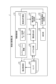
- FIG. 3 is a block diagram of an automated teller machine.
- FIG. 4 is a diagram showing an example of the arrangement of sensors.
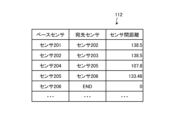
- FIG. 5 is a diagram showing an example of a sensor arrangement table in the feed direction.
- FIG. 6 is a diagram showing an example of a sensor arrangement table in the reverse direction.
- FIG. 7 is a diagram showing an example of a log in an automated teller machine.
- FIG. 8 is a diagram showing an outline of the banknote transport process indicated by the log.
- FIG. 9 is a diagram showing an example of how transport speed information is accumulated.
- FIG. 10 is a diagram illustrating an example of the abnormal tendency threshold value.
- FIG. 10 is a diagram illustrating an example of the abnormal tendency threshold value.
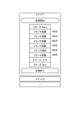
- FIG. 11 is a diagram illustrating an example of the determination result information.
- FIG. 12 is a flowchart of an abnormality sign detection process in the transport of banknotes by the automated teller machine according to the embodiment.
- FIG. 13 is a flowchart of a rendering process performed by the automated teller machine according to the embodiment.
- banknote transport device banknote transport method
- FIG. 1 is an external view of an automated teller machine.
- the automated teller machine 1 has the external appearance shown in FIG. 1.
- the automated teller machine 1 has a customer operation screen 11, a cash deposit/withdrawal section 12, a passbook acceptance section 13, a card acceptance port 14, and a receipt issuing port 15.
- the automated teller machine 1 is an example of a "banknote transport device.”
- the customer operation screen 11 is, for example, a display equipped with a touch panel, and is used when the user inputs various data including a PIN number and gives various instructions.
- the cash deposit/withdrawal unit 12 accepts deposited coins and banknotes and dispenses withdrawn coins and banknotes.
- the passbook acceptance unit 13 accepts and returns passbooks.
- the card acceptance port 14 accepts and returns cards used for transactions, such as cash cards.
- the receipt issuing port 15 dispenses receipts on which issued transaction details are printed.
- FIG. 2 is a diagram showing an example of the hardware configuration of an automated teller machine.
- the automated teller machine 1 has a main control unit 21, a memory unit 22, an input unit 23, a display unit 24, a deposit/withdrawal processing unit 25, a passbook entry processing unit 26, a card reading unit 27, a receipt issuing unit 28, and a communication processing unit 29.
- the main control unit 21, the memory unit 22, the input unit 23, the display unit 24, the deposit/withdrawal processing unit 25, the passbook entry processing unit 26, the card reading unit 27, the receipt issuing unit 28, and the communication processing unit 29 are connected by a bus 30.
- the main control unit 21 provides overall control of the automated teller machine 1.
- the main control unit 21 reads programs for performing various processes of the automated teller machine 1 that are stored in the memory unit 22 or the like, temporarily stores the programs in an internal memory (not shown), and performs various processes according to these programs.
- the main control unit 21 has, for example, a CPU (Central Processing Unit) or the like.
- the input unit 23 and the display unit 24 are equipped with the above-mentioned customer operation screen 11.
- the user refers to the various screens displayed on the display unit 24 and performs operations such as selecting and inputting the desired transaction using the input unit 23.
- the communication processing unit 29 is used for communication with the host computer 2 via the network, for example, when providing a transaction service selected by the user.
- the communication processing unit 29 is, for example, a communication interface.
- the main control unit 21 performs control to realize a transaction instructed by the user through operations on the customer operation screen 11. Specifically, when the user selects and inputs a transaction from the transaction menu displayed on the display unit 24 using the input unit 23, inserts a card or passbook, and performs the specified transaction operations, the main control unit 21 performs control to realize the transaction via the communication processing unit 29 with the host computer 2, which manages various information such as the user's account information, PIN number, and deposit amount.
- the storage unit 22 stores application programs for performing various processes of the ATM 1, data necessary for the processes of the ATM 1, and the like.
- the storage unit 22 is, for example, a hard disk drive.
- the deposit/withdrawal processing unit 25 has a banknote processing unit 250.
- the banknote processing unit 250 is a banknote transport mechanism that performs banknote transport processing.
- the banknote processing unit 250 accepts banknotes inserted into the cash deposit/withdrawal unit 12, and identifies, counts, and stores the banknotes.
- the banknote processing unit 250 also discharges a predetermined number of banknotes from the cash deposit/withdrawal unit 12 in accordance with a withdrawal transaction selected by the user.
- the deposit/withdrawal processing unit 25 may also have a coin processing unit that accepts coins inserted into the cash deposit/withdrawal unit 12 and identifies, counts, and stores the coins, and discharges a predetermined number of coins from the cash deposit/withdrawal unit 12 in accordance with a withdrawal transaction selected by the user.
- the passbook entry processing unit 26 accepts the passbook inserted by the user through the passbook reception unit 13, transports it to a specified position, records the details of the transaction processing, and returns the passbook after the recording is completed from the passbook reception unit 13.
- the card reading unit 27 accepts the card inserted by the user through the card acceptance port 14, reads data such as account information from the magnetic stripe and IC (Integrated Circuit) chip of the card, and returns the card through the card acceptance port 14.
- the receipt issuing unit 28 issues a receipt.
- FIG. 3 is a block diagram of an automated teller machine.
- the function related to detecting anomalies in the transport of banknotes by the automated teller machine 1 is described, and other functions are not shown.
- the automated teller machine 1 has a transport control unit 101, a log generation unit 102, a threshold calculation unit 103, an operation determination processing unit 104, a determination result information generation unit 105, a notification unit 106, and a sensor 200.
- the transport control unit 101, the log generation unit 102, the threshold calculation unit 103, the operation determination processing unit 104, and the determination result information generation unit 105 are realized by the main control unit 21 illustrated in FIG. 2.
- a number of sensors 200 are arranged on the banknote path within the automated teller machine 1.
- the sensors 200 detect the presence of transported banknotes at a predetermined position.
- the sensors 200 can detect the passage of banknotes at a predetermined position and the accumulation of banknotes at a predetermined position.
- the sensors 200 output the detection results of the transported banknotes to the log generation unit 102.
- FIG. 4 is a diagram showing an example of a sensor arrangement.
- sensors 201 to 212 are shown as an example of the sensor 200.
- the banknote processing unit 250 shown in FIG. 2 has a transport path 220 for transporting banknotes.
- the transport path 220 is a path connecting the cash deposit/withdrawal section 12 and the storage facility.
- the banknote processing unit 250 also has an identification section 230 that determines the authenticity of banknotes by identification.
- the banknote processing unit 250 has sensors 201 to 212 at each point on the transport path 220.
- Sensor 201 is arranged near the cash deposit/withdrawal unit 12 on the path that sends banknotes from the cash deposit/withdrawal unit 12 to the inside of the device.
- Sensor 212 is arranged near the cash deposit/withdrawal unit 12 on the path that sends banknotes inside the device to the cash deposit/withdrawal unit 12.
- Sensor 202 is arranged between sensor 201 and the validation unit 230.
- Sensors 203 and 204 are arranged between the validation unit 230 and the storage facility.
- Sensor 205 is arranged at a branching point of the path in the storage facility closest to the cash deposit/withdrawal unit 12 on the transport path 220.
- Sensor 206 is arranged at a location where banknotes are stored in the storage facility closest to the cash deposit/withdrawal unit 12 on the transport path 220.
- Sensor 207 is arranged at a branching point of the path in the storage facility second closest to the cash deposit/withdrawal unit 12 on the transport path 220.
- Sensor 208 is disposed at a location on transport path 220 where banknotes are stored in a storage unit second closest to cash deposit/withdrawal unit 12.
- Sensor 209 is disposed at a branching point on transport path 220 where banknotes are stored in a storage unit third closest to cash deposit/withdrawal unit 12.
- Sensor 210 is disposed at a location on transport path 220 where banknotes are stored in a storage unit third closest to cash deposit/withdrawal unit 12.
- Sensor 211 is disposed at a location on transport path 220 where banknotes are stored in a storage unit farthest from cash deposit/withdrawal unit 12.
- Sensors 201 to 205, 207, 209, and 212 each detect the passage of a bill. Additionally, sensors 206, 208, 210, and 211 each detect bills stored in the storage facility.
- the information storage unit 110 is realized by the memory unit 22 illustrated in FIG. 2.
- the information storage unit 110 stores log format information 111, a sensor placement table 112, and control condition information 113.
- the log format information 111 information on the format of the log in which the operation history of the automated teller machine 1 is recorded is registered.
- the log format information 111 registers information such as which item in the log is a timestamp, which item is the subject of the operation, and which item is the content of the operation.
- the sensor placement table 112 information is registered that indicates how the sensor 200 is placed in the banknote processing unit 250 shown in FIG. 2. In this embodiment, the sensor placement table 112 registers placement information for the sensors 201 to 212 shown in FIG. 4.
- the sensor arrangement table 112 in this embodiment has two types: a feed direction, which is the direction in which banknotes flow when they are taken into the automated teller machine 1, and a back direction, which is the direction in which banknotes flow when they are discharged from the automated teller machine 1.
- a feed direction which is the direction in which banknotes flow when they are taken into the automated teller machine 1
- a back direction which is the direction in which banknotes flow when they are discharged from the automated teller machine 1.
- Figure 5 is a diagram of an example of a sensor arrangement table for the feed direction.
- Figure 6 is a diagram of an example of a sensor arrangement table for the back direction.
- the base sensor that the banknote passes first along the flow of the banknote and the destination sensor that the banknote will reach next after passing the base sensor are registered.
- "END" indicates that the banknote will be accumulated at that location.
- sensors 201 to 212 are registered in the order from a start candidate sensor that can be the starting position on a transport path determined as a series of transports in transporting banknotes to a terminal candidate sensor that can be the final position.
- sensors 201 to 203 are lined up in order on a series of transport paths, with sensor 201 being a candidate start sensor and sensor 203 being a candidate end sensor.
- sensors 204 to 206 are lined up in order on a series of transport paths, with sensor 206 being a candidate start sensor and sensor 204 being a candidate end sensor.
- the inter-sensor distance between the base sensor and the destination sensor is registered in the sensor arrangement table 112.
- the inter-sensor distance between the sensor 201, which is the base sensor, and the sensor 202, which is the destination sensor is 138.5 mm.
- the control condition information 113 indicates the control conditions for dealing with irregularities in the banknote transport process.
- an abnormality determination threshold for detecting abnormalities in the transport of banknotes that is predetermined in the firmware is registered.
- the abnormality determination threshold is expressed as the transport speed of the banknotes.
- the upper threshold of the transport speed is set to 1500 mm/s, and the lower threshold is set to 375 mm/s.
- the transport control unit 101 performs control such as starting and stopping the motor during the banknote transport process.
- the transport control unit 101 acquires detection information of the transported banknotes from each sensor 200, calculates the transport speed, and compares it with the abnormality determination threshold registered in the control condition information 113 to detect abnormalities during the transport process. For example, the transport control unit 101 determines whether an abnormality has occurred based on whether the transport speed is included in the range indicated by the abnormality determination threshold, which is the range between the upper and lower abnormality determination thresholds. If an abnormality is detected, the transport control unit 101 stops the banknote transport process. In addition, the transport control unit 101 outputs information on the control that has been executed to the log generation unit 102.
- the log generating unit 102 receives input of information on the control executed in the banknote transport process from the transport control unit 101.
- the log generating unit 102 also receives input of control information for processes executed in the automated teller machine 1 other than the banknote transport process.
- the log generating unit 102 receives input of the banknote detection results in the banknote transport process from each sensor 200.
- the log generating unit 102 generates a log that is a history of various processes executed in the automated teller machine 1 of FIG. 2, including the banknote transport process.
- the log generating unit 102 creates the log according to the format stored in the log format information 111.
- the log generating unit 102 outputs the generated log in response to a log acquisition request from the threshold calculation unit 103 and the operation determination processing unit 104.
- FIG. 7 is a diagram showing an example of a log in an automated teller machine.
- the log generation unit 102 generates a log in which control information and information such as the detection results by the sensor 200 are registered in chronological order along with timestamps.
- the areas surrounded by frames 301, 302, 304, and 306 show the detection results of each sensor 200.
- the areas surrounded by frames 303 and 305 show control information such as starting and stopping the motor.
- FIG. 8 is a diagram showing an overview of the banknote transport process shown in the log.
- an overview of the banknote transport process shown in the log is described using an example in which there are an X sensor, a Y sensor, and a Z sensor as the sensor 200, and the A motor is driven.
- the contents of the log can be distinguished for each command related to the banknote transport process. Furthermore, it is possible to read information on the control performed from the start of processing for each command to the end of processing, and the detection results of the sensor 200, in chronological order from the log.
- the threshold calculation unit 103 sends a request to obtain a log to the log generation unit 102 and obtains the log in response. Furthermore, the threshold calculation unit 103 refers to the log format information 111 and the sensor arrangement table 112. Then, the threshold calculation unit 103 uses the arrangement of the sensors 200 obtained from the sensor arrangement table 112 to calculate an abnormal tendency threshold for detecting an abnormal tendency from the information registered in the log according to the log format obtained from the log format information 111. The threshold calculation unit 103 can calculate the abnormal tendency threshold after a predetermined number of days have passed since the start of operation of the automated teller machine 1 or after a predetermined number of banknotes have been transported.
- the threshold calculation unit 103 calculates the transport speed of the banknote during inter-sensor transport from each base sensor registered in the sensor arrangement table 112 to the destination sensor. For example, the threshold calculation unit 103 extracts information related to inter-sensor transport of the banknote from each base sensor registered in the sensor arrangement table 112 to the destination sensor from the log. Then, the threshold calculation unit 103 obtains the elapsed time during each inter-sensor transport extracted using the timestamp. After that, the threshold calculation unit 103 divides the elapsed time by the inter-sensor distance registered in the sensor arrangement table 112 to calculate the transport speed of the banknote during each inter-sensor transport. The threshold calculation unit 103 accumulates transport speed information for each inter-sensor transport.
- FIG. 9 is a diagram showing an example of accumulation of transport speed information.
- the threshold calculation unit 103 accumulates transport speed information for inter-sensor transport between sensors 201 and 202, between sensors 202 and 203, between sensors 203 and 204, between sensors 204 and 205, and between sensors 205 and 206.
- the threshold calculation unit 103 calculates each reference value using the transport speed information for transport between the sensors. The threshold calculation unit 103 then calculates an abnormality tendency threshold value that has a difference from the calculated reference value to a degree that can be determined as a sign of abnormality.
- the threshold calculation unit 103 calculates the average value of the transport speed information for each inter-sensor transport. Furthermore, as shown in FIG. 9, the threshold calculation unit 103 calculates the standard deviation of the transport speed information for each inter-sensor transport. Then, the threshold calculation unit 103 adds a value obtained by multiplying the standard deviation by a predetermined deviation coefficient to the average value of the transport speed information to calculate an upper limit value of the abnormal tendency threshold. Furthermore, the threshold calculation unit 103 subtracts a value obtained by multiplying the standard deviation by a predetermined deviation coefficient from the average value of the transport speed information to calculate a lower limit value of the abnormal tendency threshold.
- FIG. 10 is a diagram showing an example of an abnormal tendency threshold.
- the threshold calculation unit 103 calculates upper and lower limit abnormal tendency thresholds for inter-sensor transport between sensors 201 and 202, between sensors 202 and 203, between sensors 203 and 204, between sensors 204 and 205, and between sensors 205 and 206, as shown in FIG. 10, from the average value and standard deviation of the transport speed information shown in FIG. 9.
- the threshold calculation unit 103 outputs the calculated abnormal tendency threshold to the operation determination processing unit 104.
- the threshold calculation unit 103 outputs the upper limit and lower limit of the abnormal tendency threshold to the operation determination processing unit 104.
- the operation determination processing unit 104 obtains the abnormal tendency threshold from the threshold calculation unit 103. Thereafter, the operation determination processing unit 104 periodically transmits a request to obtain a log to the log generation unit 102, and obtains a log in response. Furthermore, the operation determination processing unit 104 refers to the log format information 111 and the sensor arrangement table 112. Then, the threshold calculation unit 103 uses the arrangement of the sensors 200 obtained from the sensor arrangement table 112 to calculate the transport speed in the transport between the sensors from the information registered in the log, according to the log format obtained from the log format information 111.
- the operation determination processing unit 104 executes a rendering process described below to calculate the transport speed of the banknotes in the inter-sensor transport from each base sensor registered in the sensor arrangement table 112 to the destination sensor.
- the operation determination processing unit 104 can also obtain information indicating the transport flow of each banknote according to the order of the sensors 200 that detected the banknotes for each command, i.e., information on whether the banknotes are flowing in the feed direction or the back direction.
- the operation determination processing unit 104 extracts a log having a pair of the start and end of the motor drive from the entire log as a log for each command that instructs the transport of the banknote. Next, the operation determination processing unit 104 identifies the transport direction of the banknote from the extracted log. Next, the operation determination processing unit 104 refers to a sensor arrangement table according to the identified transport direction of the banknote. Then, the operation determination processing unit 104 selects a pair of a base sensor and a destination sensor according to the transport of the banknote, starting from the sensor 200 that is the start candidate sensor of the extracted log, and acquires the respective sensor detection logs.
- the operation determination processing unit 104 acquires the elapsed time in the inter-sensor transport between the base sensor and the destination sensor using the timestamp of the extracted sensor detection log. After that, the operation determination processing unit 104 divides the elapsed time by the inter-sensor distance registered in the sensor arrangement table 112 to calculate the transport speed of the banknote in the inter-sensor transport between the base sensor and the destination sensor. The operation determination processing unit 104 calculates the transport speed of the banknote in the inter-sensor transport between the base sensor and the destination sensor for each sensor 200 from the start candidate sensor to the end candidate sensor included in the extracted log for each command. Furthermore, the operation determination processing unit 104 calculates the transport speed of the banknote in the inter-sensor transport between the base sensor and the destination sensor for all commands in the entire log in the same manner.
- the operation determination processing unit 104 detects the occurrence of signs of abnormality in the transport between the sensors by comparing the transport speeds calculated by the rendering process with the abnormality tendency thresholds. In this embodiment, the operation determination processing unit 104 determines the presence or absence of signs of abnormality based on whether the transport speed is included in the range indicated by the abnormality tendency thresholds, which are the upper and lower limit values of the abnormality tendency thresholds.
- the operation determination processing unit 104 detects the occurrence of an abnormal sign when the conveying speed exceeds the upper limit of the abnormal tendency threshold or falls below the lower limit of the abnormal tendency threshold. The operation determination processing unit 104 then extracts the inter-sensor conveyance in which the occurrence of an abnormal sign was detected. Thereafter, the operation determination processing unit 104 outputs the detection result of the occurrence of an abnormal sign, including information on the extracted inter-sensor conveyance, to the determination result information generation unit 105.
- the operation determination processing unit 104 may also obtain information on the abnormality determination threshold from the control condition information 113 and detect the occurrence of an abnormality by comparing the calculated transport speed in the transport between each sensor with the abnormality determination threshold. In this case, the operation determination processing unit 104 may output the detection result of the occurrence of an abnormality to the determination result information generation unit 105.
- a specific banknote is one of the large number of banknotes for which the operation determination processing unit 104 has determined whether there are signs of abnormality
- the transport speed of the specific banknote calculated by the operation determination processing unit 104 is an example of the first transport speed.
- the operation determination processing unit 104 calculates the first transport speed of the specific banknote between the sensors 200 based on the log, and determines whether there are signs of abnormality in the transport of the specific banknote between the sensors 200 depending on whether the first transport speed is within the range indicated by the abnormality tendency threshold.
- the judgment result information generating unit 105 receives input of the detection result of the occurrence of an abnormal sign from the operation judgment processing unit 104. The judgment result information generating unit 105 then generates judgment result information for notifying the detection result of the occurrence of an abnormal sign. For example, the judgment result information generating unit 105 may add the time of occurrence of the abnormal sign to information on the sensor 200, which is the base sensor and destination sensor that performed the inter-sensor transport in which the occurrence of an abnormal sign was detected, and list the information to create judgment result information. The judgment result information generating unit 105 then notifies the notification unit 106 of the generated judgment result information.
- FIG. 11 is a diagram showing an example of the judgment result information.
- the judgment result information generating unit 105 may generate judgment result information illustrating the occurrence of an abnormality sign as shown in FIG. 11.
- FIG. 11 is an example illustrating the judgment result based on the outline of the banknote transport process exemplified in FIG. 8.
- the judgment result information generating unit 105 receives an input of the detection result of the occurrence of an abnormality together with the detection result of the occurrence of an abnormality sign from the operation judgment processing unit 104. As the detection result of the occurrence of an abnormality sign, the judgment result information generating unit 105 also acquires information on the command in which the occurrence of an abnormality sign was detected, information on the flow of banknotes in processing the command, and the abnormal tendency threshold value used from the operation judgment processing unit 104. The judgment result information generating unit 105 also acquires the arrangement of the sensor 200 by referring to the sensor arrangement table 112. The judgment result information generating unit 105 also acquires the abnormality judgment threshold value from the control condition information 113.
- the judgment result information generating unit 105 creates route diagrams 401 and 402 for each banknote, in which the sensor 200 is positioned according to the information on the flow of the banknote from the start to the stop of the motor drive for each command.
- the judgment result information generating unit 105 converts the abnormal tendency threshold into a distance for each inter-sensor transport and displays ranges 411-413.
- the judgment result information generating unit 105 illustrates a line 422 indicating ⁇ y, which is the abnormal tendency threshold converted into a distance, for the inter-sensor transport in which the occurrence of an abnormal symptom is detected.
- the judgment result information generating unit 105 moves the Y sensor to a moving distance when the speed is equal to the reference value from the time taken for the second banknote shown in the route diagram 402 to be transported between the X sensor and the Y sensor. Then, ⁇ x, which is the deviation from the position of the sensor 200 when the speed is the reference value, is illustrated. As a result, since ⁇ x is longer than ⁇ y, the determination result information generating unit 105 can indicate that an abnormality has occurred in the inter-sensor transport from the X sensor to the Y sensor. Similarly, the determination result information generating unit 105 moves the Z sensor to a position calculated from the transport speed.
- ⁇ z which is the deviation from the position of the sensor 200 when the speed is the reference value, exceeds the range 413 indicating the abnormal tendency threshold, so the determination result information generating unit 105 can indicate that an abnormality has occurred in the inter-sensor transport from the Y sensor to the Z sensor.
- the notification unit 106 receives input of judgment result information including information on the inter-sensor transport in which the occurrence of an abnormal symptom was detected from the judgment result information generation unit 105.
- the notification unit 106 then notifies the administrator of the judgment result including information on the inter-sensor transport in which the occurrence of an abnormal symptom was detected, for example by transmitting the judgment result information to the host computer 2 via the communication processing unit 29 illustrated in FIG. 2.
- the notification unit 106 is realized by the main control unit 21 and communication processing unit 29 illustrated in FIG. 2.
- FIG. 12 is a flowchart of the abnormal sign detection process during the transport of banknotes by the automated teller machine according to the embodiment. Next, the flow of the abnormal sign detection process during the transport of banknotes by the automated teller machine 1 according to the embodiment will be described with reference to FIG. 12.
- the operation determination processing unit 104 reads the log generated by the log generating unit 102 (step S1).
- the operation determination processing unit 104 searches for a log pair of the start and end of motor drive (step S2).
- the operation determination processing unit 104 determines whether or not there is an unprocessed log pair of the start and end of motor drive (step S3).
- step S3 If there is an unprocessed log pair of the start and end of motor drive (step S3: Yes), the operation determination processing unit 104 extracts one log for the period from the start to the end of motor drive (step S4).
- the operation determination processing unit 104 refers to the extracted log to identify the motor drive direction (step S5).
- the operation determination processing unit 104 determines whether the motor drive direction is the feed direction (step S6).
- step S6 If the motor drive direction is the feed direction (step S6: Yes), the operation determination processing unit 104 refers to the feed direction sensor placement table 112 (step S7).
- step S6 if the motor drive direction is the reverse direction (step S6: No), the motion determination processing unit 104 refers to the sensor placement table 112 for the reverse direction (step S8).
- the operation determination processing unit 104 performs rendering processing based on the extracted log using the log format information 111 and the sensor placement table 112 (step S9).
- the operation determination processing unit 104 obtains individual rendering results for the extracted logs (step S10).
- the motion determination processing unit 104 stores the individual rendering results for the extracted logs in a temporary storage area held by the processing unit 104 (step S11). After that, the motion determination processing unit 104 returns to step S2.
- step S3 the operation determination processing unit 104 detects the occurrence of abnormal signs by comparing the transport speed in each inter-sensor transport calculated by the rendering process with the abnormal tendency threshold. Then, the operation determination processing unit 104 determines whether or not there is an inter-sensor transport in which an abnormal sign has occurred (step S12). If there is no inter-sensor transport in which an abnormal sign has occurred (step S12: No), the operation determination processing unit 104 proceeds to step S14.
- step S12 if there is a sensor-to-sensor transfer in which an abnormality symptom has occurred (step S12: Yes), the operation determination processing unit 104 extracts the sensor-to-sensor transfer in which an abnormality symptom has occurred (step S13).
- the judgment result information generating unit 105 generates judgment result information including information about the inter-sensor transport in which the occurrence of an abnormality symptom was detected as notified by the operation judgment processing unit 104 (step S14).
- the notification unit 106 notifies the administrator of the information on the inter-sensor transport in which the occurrence of an abnormality symptom was detected, for example by sending the judgment result information generated by the judgment result information generation unit 105 to the host computer 2 (step S15).
- FIG. 13 is a flowchart of the rendering process by the automated teller machine according to the embodiment. Each process shown in FIG. 13 is an example of the process executed in step S9 in FIG. 12. Next, the flow of the rendering process by the automated teller machine 1 according to the embodiment will be described with reference to FIG. 13.
- the operation determination processing unit 104 acquires the sensor detection log, which describes the detection information by the sensor 200, from the extracted logs (step S101).
- the operation determination processing unit 104 determines whether or not the acquired sensor detection logs include a sensor detection log notified by the sensor 200 that is the candidate start sensor (step S102).
- the operation determination processing unit 104 identifies the start candidate sensor with the smallest timestamp and sets it as the base sensor (step S103).
- the operation determination processing unit 104 increments the banknote count information (step S104). This enables the operation determination processing unit 104 to distinguish between the transport processes of each banknote when multiple banknotes are processed in a series of processes executed by one command.
- the operation determination processing unit 104 determines whether the base sensor is a candidate end sensor (step S105). If the base sensor is a candidate end sensor (step S105: Yes), the operation determination processing unit 104 returns to step S102.
- step S105 if the base sensor is not a candidate termination sensor (step S105: No), the operation determination processing unit 104 refers to the sensor placement table 112 (step S106).
- the operation determination processing unit 104 obtains the design distance, which is the sensor-to-sensor distance between the destination sensor and the base sensor and the destination sensor relative to the base sensor (step S107).
- the operation determination processing unit 104 extracts the sensor detection log with the smallest timestamp for the destination sensor (step S108).
- the operation determination processing unit 104 uses the timestamp to calculate the time required for sensor-to-sensor transport between the base sensor and the destination sensor, and calculates the transport speed by dividing the calculated time by the design distance (step S109).
- the operation determination processing unit 104 stores the calculated transport speed in its own temporary storage area (step S110).
- the operation determination processing unit 104 deletes the sensor detection log of the base sensor used from the acquired logs (step S111).
- step S112 the operation determination processing unit 104 sets the destination sensor to the base sensor (step S112). After that, the operation determination processing unit 104 returns to step S105.
- the operation determination processing unit 104 outputs the transport speeds for transport between each sensor stored in the temporary storage area (step S113).
- the automated teller machine which is a banknote transport device, calculates an abnormal tendency threshold from the transport state of a large amount of transported banknotes, and identifies the transport of banknotes whose transport speed exceeds the abnormal tendency threshold from the log, thereby detecting the occurrence of abnormal signs.
- an automated teller machine has been described as an example of a banknote transport device, but this is not limited to this as long as it is a device that transports banknotes.
- SCO systems Self-Check Out Systems
- self-checkout registers and ticket vending machines are also banknote transport devices, and the mechanism described in the above embodiment can be adopted.
Landscapes
- Physics & Mathematics (AREA)
- General Physics & Mathematics (AREA)
- Business, Economics & Management (AREA)
- Accounting & Taxation (AREA)
- Controlling Sheets Or Webs (AREA)
Abstract
搬送制御部(101)は、複数の紙幣を搬送経路で順次搬送する搬送処理を行う。複数のセンサ(200)は、搬送経路上に設けられ、搬送される紙幣を検知する。ログ生成部(102)は、センサ(200)による検知結果を含む過去の動作情報が記録されたログを生成する。閾値算出部(103)は、ログに含まれる搬送された複数の紙幣のセンサ(200)による検知結果を基に、センサ(200)間の紙幣の搬送について、搬送速度の異常傾向閾値を算出する。動作判定処理部(104)は、ログを基に、センサ(200)間の特定紙幣の第1搬送速度を算出し、第1搬送速度が異常傾向閾値で示される範囲に含まれるか否かにより、センサ間の特定紙幣の搬送における異常の兆候の有無を判定する。通知部(106)は、動作判定処理部(104)による判定結果を通知する。
Description
本発明は、紙幣搬送装置、紙幣搬送方法及び紙幣搬送プログラムに関する。
現金自動預払機(ATM:Automated Teller Machine)等の紙幣取扱装置は、入金された紙幣を収納する収納庫を有する。例えば、現金自動預払機は、現金の預け入れの場合には、投入取り出し口に紙幣が入れられると、紙幣を装置内で搬送して、紙幣の真贋等を鑑別する鑑別部を通過させ、収納庫に収納する。逆に、現金の引き出しの場合には、現金自動預払機は、収納庫に収納された紙幣を扱装置内で搬送して、投入取り出し口に排出する。
このような紙幣の搬送を行う紙幣搬送装置には、現金自動預払機の他にもCD(Cash Dispenser)やTCR(Teller Cash Recycler)といった様々な装置が存在する。ここで、紙幣搬送装置において、紙幣の搬送に問題が発生することが考えられる。このような問題の発生には様々な要因が考えられるが、一例として、環境温度等の変化によりローラ用の樹脂が膨張して紙幣の搬送が不安定になることが考えられる。また、古い紙幣等では、ジャムが発生して、搬送が停止する場合もある。
従来、紙幣搬送装置において問題が生じた際には、保守要員などの作業員が、装置内部の動作を記録した情報であるログを取得して、取得したログから問題解決の糸口をつかみ解析を行うことで問題解決にあたっていた。このような作業を行う作業員には、紙幣搬送装置の制御条件及び装置の仕組みの十分な理解が要求される。
なお、紙幣搬送装置の搬送における問題の対処法として、紙幣の通過を検知する第1センサ及び第2センサを設け、第1センサと第2センサとの間の紙幣の通過時間により搬送の異常を検知する技術が提案されている。他にも、媒体の搬送における異常検知の技術として、異常発生時の媒体が通過したセンサに対するその媒体の位置により、異常個所を特定する技術が提案されている。
しかしながら、異常要因の解析に用いられるログは紙幣搬送装置の時系列での動作の履歴であるため、紙幣搬送装置について十分な知識を有する技術者が、異常が発生した時刻から制御条件にしたがって異常な点を洗い出していく作業を行うことになる。この作業は、非常に工数がかかる。また、この作業には、紙幣搬送装置の制御条件及び装置の仕組みを十分に理解した技術者が求められる。そのため、紙幣搬送装置に異常が発生した際に異常要因の解析を行うためのハードルが高く、保守性を向上させることは困難であった。
開示の技術は、上記に鑑みてなされたものであって、保守性を向上させる紙幣搬送装置、紙幣搬送方法及び紙幣搬送プログラムを提供することを目的とする。
本願の開示する紙幣搬送装置、紙幣搬送方法及び紙幣搬送プログラムの一つの態様において、搬送制御部は、複数の紙幣を搬送経路で順次搬送する搬送処理を行う。複数のセンサは、前記搬送経路上に設けられ、搬送される紙幣を検知する。ログ生成部は、前記センサによる検知結果を含む過去の動作情報が記録されたログを生成する。閾値算出部は、前記ログに含まれる搬送された前記複数の紙幣の前記センサによる検知結果を基に、前記センサ間の紙幣の搬送について、搬送速度の異常傾向閾値を算出する。動作判定処理部は、前記ログを基に、前記センサ間の特定紙幣の第1搬送速度を算出し、前記第1搬送速度が前記異常傾向閾値で示される範囲に含まれるか否かにより、前記センサ間の前記特定紙幣の搬送における異常の兆候の有無を判定する。通知部は、前記動作判定処理部による判定結果を通知する。
本願の開示する紙幣搬送装置、紙幣搬送方法及び紙幣搬送プログラムの一つの態様によれば、保守性を向上させることができるという効果を奏する。
以下に、本願の開示する紙幣搬送装置、紙幣搬送方法及び紙幣搬送プログラムの実施例を図面に基づいて詳細に説明する。なお、以下の実施例により本願の開示する紙幣搬送装置、紙幣搬送方法及び紙幣搬送プログラムが限定されるものではない。
図1は、現金自動預払機の外観図である。現金自動預払機1は、図1に示す外観を有する。現金自動預払機1は、顧客操作画面11、現金入出金部12、通帳受付部13、カード受付口14及びレシート発行口15を有する。現金自動預払機1が、「紙幣搬送装置」の一例にあたる。
顧客操作画面11は、例えば、タッチパネルを備えるディスプレイであり、暗証番号の入力を含む各種データ入力および各種指示などを利用者が行う際に用いられる。現金入出金部12は、入金硬貨や入金紙幣の受け付け、及び、出金硬貨や出金紙幣の排出を行う。通帳受付部13は、通帳の受け付け及び返却を行う。カード受付口14は、キャッシュカード等の取引に使用されるカードの受け付け及び返却を行う。レシート発行口15は、発行された取引明細が印刷されたレシートの排出を行う。
図2は、現金自動預払機のハードウェア構成の一例を示す図である。現金自動預払機1は、図2に示すように、主制御部21、記憶部22、入力部23、表示部24、入出金処理部25、通帳記入処理部26、カード読取部27、レシート発行部28及び通信処理部29を有する。主制御部21、記憶部22、入力部23、表示部24、入出金処理部25、通帳記入処理部26、カード読取部27、レシート発行部28及び通信処理部29は、バス30により接続される。
主制御部21は、現金自動預払機1を統括的に制御する。主制御部21は、記憶部22等に記憶された現金自動預払機1の各種処理を行うためのプログラムを読み込み、読み込んだプログラムを内部メモリ(不図示)に一時的に格納し、このプログラムにしたがって各種処理を行う。主制御部21は、例えばCPU(Central Processing Unit)等を有する。
入力部23と表示部24は、上記顧客操作画面11を備える。利用者は、表示部24に表示される各種画面を参照して、入力部23を用いて所望の取引の選択入力等の操作を行う。
通信処理部29は、利用者が選択した取引のサービスを提供する際等に、ネットワークを介したホストコンピュータ2との間の通信に用いられる。通信処理部29は、例えば通信インタフェースである。
主制御部21は、利用者が顧客操作画面11上の操作で指示した取引を実現するための制御を行う。具体的には、主制御部21は、表示部24に表示される取引メニューから利用者が取引を入力部23により選択入力し、カードまたは通帳の挿入、及び所定の取引操作が行われると、通信処理部29を介して、ユーザの口座情報、暗証番号、預金額などの各種情報を管理するホストコンピュータ2との間で取引を実現する制御を行う。
記憶部22は、現金自動預払機1の各種処理を行うためのアプリケーションプログラムや、現金自動預払機1の処理に必要なデータなどを記憶する。記憶部22は、例えばハードディスクドライブ等である。
入出金処理部25は、紙幣処理ユニット250を有する。紙幣処理ユニット250は、紙幣搬送処理を行う紙幣搬送機構である。紙幣処理ユニット250は、現金入出金部12に投入された紙幣を受け入れ、紙幣の鑑別、計数及び収納を行う。また、紙幣処理ユニット250は、利用者によって選択された出金取引に応じて所定数の紙幣を現金入出金部12から排出する。なお、入出金処理部25は、現金入出金部12に投入された硬貨を受け入れて硬貨を鑑別、計数及び収納する処理や、利用者によって選択された出金取引に応じて所定数の硬貨を現金入出金部12から排出する処理を行う硬貨処理ユニットを有してもよい。
通帳記入処理部26は、利用者が通帳受付部13から挿入した通帳を受け付けて所定の位置まで搬送し、取引処理の内容を記帳し、記帳が完了した通帳を通帳受付部13から返却する。
カード読取部27は、利用者がカード受付口14から挿入したカードを受け付けて、カードの磁気ストライプ部やIC(Integrated Circuit)チップ部から口座情報等のデータの読み取りを行い、カードをカード受付口14から返却する。レシート発行部28は、レシートを発行する。
図3は、現金自動預払機のブロック図である。図3では、現金自動預払機1の紙幣搬送における異常検知に関する機能について記載し、他の機能については図示を省略した。
現金自動預払機1は、図3に示すように、搬送制御部101、ログ生成部102、閾値算出部103、動作判定処理部104、判定結果情報生成部105、通知部106及びセンサ200を有する。搬送制御部101、ログ生成部102、閾値算出部103、動作判定処理部104及び判定結果情報生成部105は、図2に例示した主制御部21により実現される。
センサ200は、現金自動預払機1内の紙幣経路上に複数配置される。センサ200は、搬送される紙幣の所定位置における存在の検知行う。例えば、センサ200は、所定位置の紙幣の通過や、所定位置への紙幣の蓄積を検知することができる。センサ200は、搬送される紙幣の検知結果をログ生成部102へ出力する。
図4は、センサの配置の一例を示す図である。図4では、センサ200の例として、センサ201~212を示した。例えば、図2に示す紙幣処理ニット250は、紙幣を搬送するための搬送経路220を有する。搬送経路220は、現金入出金部12と格納庫とを結ぶ経路である。また、紙幣処理ユニット250は、鑑別により紙幣の真贋等を判定する鑑別部230を有する。さらに、紙幣処理ユニット250は、搬送経路220の各地点に、センサ201~212を有する。
センサ201は、紙幣を現金入出金部12から装置内部へ送る経路上の現金入出金部12の近傍に配置される。センサ212は、装置内部の紙幣を現金入出金部12へ送る経路上の現金入出金部12の近傍に配置される。センサ202は、センサ201と鑑別部230との間に配置される。また、センサ203及び204は、鑑別部230と格納庫までの間に配置される。また、センサ205は、搬送経路220において現金入出金部12に最も近い格納庫における経路の分岐位置に配置される。センサ206は、搬送経路220において現金入出金部12に最も近い格納庫の紙幣が格納される場所に配置される。また、センサ207は、搬送経路220において現金入出金部12に2番目に近い格納庫における経路の分岐位置に配置される。センサ208は、搬送経路220において現金入出金部12に2番目に近い格納庫の紙幣が格納される場所に配置される。また、センサ209は、搬送経路220において現金入出金部12に3番目に近い格納庫における経路の分岐位置に配置される。センサ210は、搬送経路220において現金入出金部12に3番目に近い格納庫の紙幣が格納される場所に配置される。また、センサ211は、搬送経路220において現金入出金部12から最も遠い格納庫の紙幣が格納される場所に配置される。
センサ201~205、207、209及び212は、それぞれ紙幣の通過を検知する。また、センサ206、208、210及び211は、それぞれ格納庫に格納された紙幣を検知する。
図3に戻って説明を続ける。情報格納部110は、図2に例示した記憶部22により実現される。情報格納部110は、ログフォーマット情報111、センサ配置テーブル112及び制御条件情報113を格納する。
ログフォーマット情報111は、現金自動預払機1の動作の履歴が記載されたログの記載形式の情報が登録される。例えば、ログフォーマット情報111は、ログのどの項目がタイムスタンプであり、どの項目が動作主体であり、どの項目が動作内容であるかといった情報が登録される。
センサ配置テーブル112は、図2に示した紙幣処理ユニット250においてセンサ200がどのように配置されているかを示す情報が登録される。本実施例では、センサ配置テーブル112は、図4に示すセンサ201~212の配置情報が登録される。
本実施例に係るセンサ配置テーブル112は、現金自動預払機1の中に取り込む場合の紙幣の流れる方向であるフィード方向と、現金自動預払機1の中の紙幣を排出する場合の紙幣の流れる方向であるバック方向との2種類が存在する。図5は、フィード方向のセンサ配置テーブルの一例の図である。また、図6は、バック方向のセンサ配置テーブルの一例の図である。
例えば、フィード方向及びバック方向のセンサ配置テーブル112は、いずれも、紙幣の流れに沿って、先に紙幣が通過するベースセンサとベースセンサを通過した紙幣が次に到達する宛先センサとが登録される。図5及び6において、「END」は紙幣がその場所に蓄積されることを示す。センサ配置テーブル112は、紙幣の搬送における一連の搬送として決められた搬送経路における開始位置となり得る開始候補センサから最後の位置となり得る終端候補センサまでの順にセンサ201~212が登録される。
例えば、図5のセンサ配置テーブル112に示すように、フィード方向には、一連の搬送経路上に、センサ201~203が順番に並び、センサ201が開始候補センサであり、センサ203が終端候補センサである。また、図6のセンサ配置テーブル112に示すように、バック方向には、一連の搬送経路上に、センサ204~206が順番に並び、センサ206が開始候補センサであり、センサ204が終端候補センサである。
さらに、センサ配置テーブル112には、ベースセンサと宛先センサとの間のセンサ間距離が登録される。例えば、図5のセンサ配置テーブル112に示すように、ベースセンサであるセンサ201と宛先センサであるセンサ202とのセンサ間距離は、138.5mmである。
制御条件情報113は、紙幣搬送処理におけるイレギュラーな対処のための制御条件を示す。例えば、ファームウェアにおいて予め決められた紙幣の搬送の異常を検知するための異常判定閾値などが登録される。本実施例では、異常判定閾値は、紙幣の搬送速度で表される。たとえば、異常判定閾値として、搬送速度の上限の閾値が1500mm/sと設定され、下限の閾値が375mm/sと設定される。
搬送制御部101は、例えば、紙幣搬送処理においてモータの駆動開始や停止といった制御を行う。他にも、搬送制御部101は、各センサ200の搬送される紙幣の検出情報を取得して搬送速度を算出し、制御条件情報113に登録された異常判定閾値と比較して、搬送処理における異常検出を行う。例えば、搬送制御部101は、上限値及び下限値の異常判定閾値に挟まれた範囲を異常判定閾値が示す範囲として、異常判定閾値が示す範囲に搬送速度が含まれるか否かにより異常が発生した否かを判定する。異常を検出した場合、搬送制御部101は、紙幣搬送処理を停止する。また、搬送制御部101は、実行した制御の情報をログ生成部102へ出力する。
ログ生成部102は、紙幣搬送処理における実行された制御の情報の入力を搬送制御部101から受ける。ここで、ログ生成部102は、紙幣搬送処理以外の現金自動預払機1において実行される処理についても制御の情報の入力を受ける。また、ログ生成部102は、紙幣搬送処理における紙幣の検知結果の入力を各センサ200から受ける。
そして、ログ生成部102は、紙幣搬送処理を含む図2の現金自動預払機1において実行される各種処理の履歴であるログを生成する。ログ生成部102は、ログフォーマット情報111に格納されたフォーマットにしたがってログを作成する。ログ生成部102は、閾値算出部103及び動作判定処理部104からのログの取得要求に応じて、生成したログを出力する。
図7は、現金自動預払機におけるログの一例を示す図である。図7に示すように、ログ生成部102は、制御の情報及びセンサ200による検知結果等の情報をタイムスタンプとともに時系列で登録したログを生成する。例えば、図7において、枠線301、302、304及び306で囲われた部分は、各センサ200の検知結果を示す。また、枠線303及び305で囲われた部分は、モータの駆動開始及び停止等の制御の情報を示す。
図8は、ログで示される紙幣搬送処理の概要を示す図である。図8では、センサ200としてXセンサ、Yセンサ及びZセンサが存在し、且つ、Aモータが駆動する場合を例に、ログで示される紙幣搬送処理の概要を記載した。ログの内容は、紙幣搬送処理に関するコマンド毎に区別可能である。そして、各コマンドについての処理の開始から処理終了までに行われる制御の情報及びセンサ200の検知結果を、時系列順にログから読み取ることが可能である。
閾値算出部103は、ログの取得要求をログ生成部102へ送信して、その応答としてログを取得する。さらに、閾値算出部103は、ログフォーマット情報111及びセンサ配置テーブル112を参照する。そして、閾値算出部103は、センサ配置テーブル112から得られるセンサ200の配置を用いて、ログフォーマット情報111から得られるログのフォーマットにしたがい、ログに登録された情報から異常傾向を検知するための異常傾向閾値を算出する。閾値算出部103は、現金自動預払機1の運用開始から所定日数経過後や所定枚数の紙幣の搬送後に異常傾向閾値を算出することができる。
例えば、閾値算出部103は、センサ配置テーブル112に登録されたそれぞれのベースセンサから宛先センサへの紙幣のセンサ間搬送における搬送速度を算出する。例えば、閾値算出部103は、センサ配置テーブル112に登録されたそれぞれのベースセンサから宛先センサへの紙幣のセンサ間搬送に関する情報をログから抽出する。そして、閾値算出部103は、タイムスタンプを用いて抽出した各センサ間搬送における経過時間を取得する。その後、閾値算出部103は、経過時間をセンサ配置テーブル112に登録されたセンサ間距離で除算して、各センサ間搬送における紙幣の搬送速度を算出する。閾値算出部103は、各センサ間搬送における搬送速度情報を蓄積する。
図9は、搬送速度情報の蓄積例を示す図である。例えば、閾値算出部103は、センサ201とセンサ202との間、センサ202とセンサ203との間、センサ203とセンサ204との間、センサ204とセンサ205との間、センサ205とセンサ206との間のセンサ間搬送の搬送速度情報を蓄積する。
次に、閾値算出部103は、各センサ間搬送における搬送速度情報を用いてそれぞれの基準値を算出する。そして、閾値算出部103は、算出した基準値から異常の兆候と判定できる程度の差を有する異常傾向閾値を算出する。
例えば、閾値算出部103は、図9に示すように、各センサ間搬送について搬送速度情報の平均値を算出する。さらに、閾値算出部103は、図9に示すように、各センサ間搬送について搬送速度情報の標準偏差を算出する。そして、閾値算出部103は、搬送速度情報の平均値の値に、標準偏差に予め決められた偏差係数を乗算した値を加算して、異常傾向閾値の上限値を算出する。また、閾値算出部103は、搬送速度情報の平均の値から、標準偏差に予め決められた偏差係数を乗算した値を減算して、異常傾向閾値の下限値を算出する。
例えば、偏差係数が5の場合、閾値算出部103は、異常傾向閾値の上限値=平均値+(標準偏差×5)とし、異常傾向閾値の下限値=平均値-(標準偏差×5)とする。また、偏差係数が10の場合、閾値算出部103は、異常傾向閾値の上限値=平均値+(標準偏差×10)とし、異常傾向閾値の下限値=平均値-(標準偏差×10)とする。
図10は、異常傾向閾値の一例を示す図である。例えば、閾値算出部103は、図9に示した搬送速度情報から平均値及び標準偏差から、図10に示す、センサ201とセンサ202との間、センサ202とセンサ203との間、センサ203とセンサ204との間、センサ204とセンサ205との間、センサ205とセンサ206との間のセンサ間搬送の異常傾向閾値の上限値及び下限値を算出する。
そして、閾値算出部103は、算出した異常傾向閾値を動作判定処理部104へ出力する。本実施例では、閾値算出部103は、異常傾向閾値の上限値及び下限値を動作判定処理部104へ出力する。
図3に戻って説明を続ける。動作判定処理部104は、異常傾向閾値を閾値算出部103から取得する。その後、動作判定処理部104は、ログの取得要求をログ生成部102へ定期的に送信して、その応答としてログを取得する。さらに、動作判定処理部104は、ログフォーマット情報111及びセンサ配置テーブル112を参照する。そして、閾値算出部103は、センサ配置テーブル112から得られるセンサ200の配置を用いて、ログフォーマット情報111から得られるログのフォーマットにしたがい、ログに登録された情報から各センサ間搬送における搬送速度を算出する。
例えば、動作判定処理部104は、以下に説明するレンダリング処理を実行して、センサ配置テーブル112に登録されたそれぞれのベースセンサから宛先センサへの紙幣のセンサ間搬送における搬送速度を算出する。動作判定処理部104は、レンダリング処理を行うことで、コマンド毎に、紙幣を検知したセンサ200の順番により各紙幣の搬送の流れを示す情報、すなわち、紙幣がフィード方向に流れるかバック方向に流れるかといった情報も取得することができる。
例えば、動作判定処理部104は、紙幣搬送を指示するコマンド毎のログとして、モータの駆動の開始及び終了のペアを有するログをログ全体から抽出する。次に、動作判定処理部104は、抽出したログから紙幣の搬送方向を特定する。次に、動作判定処理部104は、特定した紙幣の搬送方向に応じたセンサ配置テーブルを参照する。そして、動作判定処理部104は、抽出したログの開始候補センサにあたるセンサ200から順に紙幣の搬送にしたがって、ベースセンサ及び宛先センサの組を選び、それぞれのセンサ検知ログを取得する。次に、動作判定処理部104は、抽出したセンサ検知ログのタイムスタンプを用いてベースセンサと宛先センサとの間のセンサ間搬送における経過時間を取得する。その後、動作判定処理部104は、経過時間をセンサ配置テーブル112に登録されたセンサ間距離で除算して、ベースセンサと宛先センサとの間のセンサ間搬送における紙幣の搬送速度を算出する。動作判定処理部104は、コマンド毎の抽出したログに含まれる開始候補センサから終端候補センサまでの各センサ200についてベースセンサと宛先センサとの間のセンサ間搬送における紙幣の搬送速度を算出する。さらに、動作判定処理部104は、ログ全体について全てのコマンドに対して同様に、ベースセンサと宛先センサとの間のセンサ間搬送における紙幣の搬送速度を算出する。
その後、動作判定処理部104は、レンダリング処理により算出した各センサ間搬送における搬送速度と異常傾向閾値とを比較してセンサ間搬送における異常の兆候の発生を検知する。本実施例では、動作判定処理部104は、上限値及び下限値の異常傾向閾値に挟まれた範囲を異常傾向閾値が示す範囲として、異常傾向閾値が示す範囲に搬送速度が含まれるか否かにより異常の兆候の有無を判定する。
例えば、動作判定処理部104は、搬送速度が異常傾向閾値の上限値を越えた場合又は搬送速度が異常傾向閾値の下限値を下回った場合に、異常兆候の発生を検知する。そして、動作判定処理部104は、異常兆候の発生を検知したセンサ間搬送を抽出する。その後、動作判定処理部104は、抽出したセンサ間搬送の情報を含む異常兆候の発生の検知結果を判定結果情報生成部105へ出力する。
また、動作判定処理部104は、制御条件情報113から異常判定閾値の情報を取得して、算出した各センサ間搬送における搬送速度と異常判定閾値とを比較して、異常発生を検知してもよい。この場合、動作判定処理部104は、異常発生の検知結果を判定結果情報生成部105へ出力してもよい。
動作判定処理部104が異常の兆候の有無の判定を行った大量の紙幣のうちの1枚が、特定紙幣にあたり、動作判定処理部104により算出されたその特定紙幣の搬送速度が第1搬送速度の一例にあたる。すなわち、動作判定処理部104は、ログを基に、センサ200間の特定紙幣の第1搬送速度を算出し、第1搬送速度が異常傾向閾値で示される範囲に含まれるか否かにより、センサ200間の特定紙幣の搬送における異常の兆候の有無を判定する。
判定結果情報生成部105は、異常兆候の発生の検知結果の入力を動作判定処理部104から受ける。そして、判定結果情報生成部105は、異常兆候の発生の検知結果を通知するための判定結果情報を生成する。例えば、判定結果情報生成部105は、異常兆候の発生が検知されたセンサ間搬送を行ったベースセンサ及び宛先センサであるセンサ200の情報に異常兆候の発生時刻を付加してリスト化して、判定結果情報としてもよい。その後、判定結果情報生成部105は、生成した判定結果情報を通知部106に通知する。
図11は、判定結果情報の一例を示す図である。他にも、判定結果情報生成部105は、図11に示すような異常兆候の発生を図示した判定結果情報を生成してもよい。図11は、図8に例示した紙幣搬送処理の概要に基づく判定結果を図示した例である。
例えば、判定結果情報生成部105は、異常兆候の発生の検知結果とともに異常発生の検知結果の入力を動作判定処理部104から受ける。判定結果情報生成部105は、異常兆候の発生の検知結果として、異常兆候の発生が検知されたコマンドの情報、そのコマンドの処理における紙幣の流れの情報及び使用された異常傾向閾値も動作判定処理部104から取得する。また、判定結果情報生成部105は、センサ配置テーブル112を参照してセンサ200の配置を取得する。また、判定結果情報生成部105は、制御条件情報113から異常判定閾値を取得する。
そして、判定結果情報生成部105は、図11に示すように、コマンド毎にモータの駆動開始から停止までの、紙幣の流れの情報にしたがってセンサ200を配置した経路図401及び402を紙幣毎に作成する。次に、判定結果情報生成部105は、各センサ間搬送について異常傾向閾値を距離に直して範囲411~413を表示する。さらに、判定結果情報生成部105は、異常兆候の発生が検知されたセンサ間搬送に、異常傾向閾値を距離に直したΔyを示す線422を図示する。また、判定結果情報生成部105は、経路図402に示される2枚目の紙幣がXセンサからYセンサの間を搬送される際にかかった時間から基準値にあたる速度の場合の移動距離にYセンサを移動させる。そして、速度が基準値の場合のセンサ200の位置からのずれであるΔxを図示する。これにより、判定結果情報生成部105は、ΔxがΔyより長いことから、XセンサからYセンサへのセンサ間搬送で異常兆候が発生したことを示すことができる。また、判定結果情報生成部105は、Zセンサについても同様に搬送速度から算出される位置に移動させる。この場合、速度が基準値の場合のセンサ200の位置からのずれであるΔzが、異常傾向閾値を示す範囲413を越えるので、判定結果情報生成部105は、YセンサからZセンサへのセンサ間搬送で異常が発生したことを示すことができる。
図3に戻って説明を続ける。通知部106は、異常兆候の発生が検知されたセンサ間搬送の情報を含む判定結果情報の入力を判定結果情報生成部105から受ける。そして、通知部106は、図2に例示した通信処理部29を介してホストコンピュータ2に判定結果情報を送信する等して、管理者に異常兆候の発生が検知されたセンサ間搬送の情報を含む判定結果を通知する。通知部106は、図2に例示した主制御部21及び通信処理部29により実現される。
図12は、実施例に係る現金自動預払機による紙幣搬送における異常兆候検知処理のフローチャートである。次に、図12を参照して、実施例に係る現金自動預払機1による紙幣搬送における異常兆候検知処理の流れを説明する。
動作判定処理部104は、ログ生成部102により生成されたログを読み込む(ステップS1)。
次に、動作判定処理部104は、モータ駆動の開始及び終了のペアのログを探索する(ステップS2)。
そして、動作判定処理部104は、未処理のモータ駆動の開始及び終了のペアのログが存在するか否かを判定する(ステップS3)。
未処理のモータ駆動の開始及び終了のペアのログが存在する場合(ステップS3:肯定)、動作判定処理部104は、モータ駆動の開始から終了までの期間のログを1つ抽出する(ステップS4)。
次に、動作判定処理部104は、抽出したログを参照してモータ駆動方向を特定する(ステップS5)。
そして、動作判定処理部104は、モータ駆動方向がフィード方向か否かを判定する(ステップS6)。
モータ駆動方向がフィード方向の場合(ステップS6:肯定)、動作判定処理部104は、フィード方向のセンサ配置テーブル112を参照する(ステップS7)。
これに対して、モータ駆動方向がバック方向の場合(ステップS6:否定)、動作判定処理部104は、バック方向のセンサ配置テーブル112を参照する(ステップS8)。
次に、動作判定処理部104は、抽出したログを基に、ログフォーマット情報111及びセンサ配置テーブル112を用いてレンダリング処理を実施する(ステップS9)。
次に、動作判定処理部104は、抽出したログに対する個別のレンダリング結果を取得する(ステップS10)。
そして、動作判定処理部104は、抽出したログに対する個別のレンダリング結果を自己が保持する一時的な格納領域に格納する(ステップS11)。その後、動作判定処理部104は、ステップS2へ戻る。
一方、取得したログに含まれるモータ駆動の開始及び終了のペアのログの全ての処理が完了した場合(ステップS3:否定)、動作判定処理部104は、レンダリング処理により算出した各センサ間搬送における搬送速度と異常傾向閾値とを比較して異常兆候の発生の検知を行う。そして、動作判定処理部104は、異常兆候が発生したセンサ間搬送が存在するか否かを判定する(ステップS12)。異常兆候が発生したセンサ間搬送が存在しない場合(ステップS12:否定)、動作判定処理部104は、ステップS14へ進む。
これに対して、異常兆候が発生したセンサ間搬送が存在する場合(ステップS12:肯定)、動作判定処理部104は、異常兆候が発生したセンサ間搬送を抽出する(ステップS13)。
その後、判定結果情報生成部105は、動作判定処理部104により通知された異常兆候の発生が検知されたセンサ間搬送の情報を含む判定結果情報を生成する(ステップS14)。
通知部106は、判定結果情報生成部105により生成された判定結果情報をホストコンピュータ2へ送信する等して、異常兆候の発生が検知されたセンサ間搬送の情報を管理者に通知する(ステップS15)。
図13は、実施例に係る現金自動預払機によるレンダリング処理のフローチャートである。図13に示した各処理は、図12におけるステップS9で実行される処理の一例にあたる。次に、図13を参照して、実施例に係る現金自動預払機1によるレンダリング処理の流れを説明する。
動作判定処理部104は、抽出したログの中からセンサ200による検知情報が記載されたセンサ検知ログを取得する(ステップS101)。
次に、動作判定処理部104は、取得したセンサ検知ログの中に、開始候補センサであるセンサ200により通知されたセンサ検知ログが存在するか否かを判定する(ステップS102)。
開始候補センサであるセンサ200により通知されたセンサ検知ログが存在する場合(ステップS102:肯定)、動作判定処理部104は、タイムスタンプが最小の開始候補センサを特定してベースセンサとする(ステップS103)。
次に、動作判定処理部104は、紙幣枚数情報をインクリメントする(ステップS104)。これにより、動作判定処理部104は、1つのコマンドにより実行される一連の処理において複数の紙幣が処理される場合に、それぞれの紙幣の搬送処理を区別することが可能となる。
次に、動作判定処理部104は、ベースセンサが終了候補センサか否かを判定する(ステップS105)。ベースセンサが終了候補センサの場合(ステップS105:肯定)、動作判定処理部104は、ステップS102へ戻る。
これに対して、ベースセンサが終了候補センサでない場合(ステップS105:否定)、動作判定処理部104は、センサ配置テーブル112を参照する(ステップS106)。
そして、動作判定処理部104は、ベースセンサに対する宛先センサ及びベースセンサと宛先センサとのセンサ間距離である設計距離を取得する(ステップS107)。
次に、動作判定処理部104は、宛先センサの最もタイムスタンプが小さいセンサ検出ログを抽出する(ステップS108)。
次に、動作判定処理部104は、タイムスタンプを用いてベースセンサと宛先センサとの間のセンサ間搬送にかかった時間を算出し、算出した時間を設計距離で除算して搬送速度を算出する(ステップS109)。
次に、動作判定処理部104は、算出した搬送速度を自己が有する一時的な記憶領域に記憶する(ステップS110)。
次に、動作判定処理部104は、取得したログの中から使用したベースセンサのセンサ検知ログを削除する(ステップS111)。
次に、動作判定処理部104は、宛先センサをベースセンサに設定する(ステップS112)。その後、動作判定処理部104は、ステップS105へ戻る。
一方、開始候補センサであるセンサ200により通知されたセンサ検知ログが存在しない場合(ステップS102:否定)、動作判定処理部104は、一時的な記憶領域に記憶した各センサ間搬送における搬送速度を出力する(ステップS113)。
以上に説明したように、紙幣搬送装置である本実施例に係る現金自動預払機は、大量に搬送する紙幣の搬送状態から異常傾向閾値を算出し、ログの中から搬送速度が異常傾向閾値を越えた紙幣の搬送を特定して異常兆候の発生を検知する。
このように、異常が実際に発生するよりも前の段階での異常の兆候の発生を検知することで、異常が発生した紙幣における異常要因を、大量に紙幣を流す紙幣搬送装置の特性に応じたその他の正常であった紙幣との比較から抽出することが可能となる。すなわち、異常発生の時点や箇所に限定することなく、紙幣搬送装置の特性に合わせて紙幣搬送処理の異常要因を検知することができ、適切な異常要因の特定を実現することができる。これにより、異常要因の特定が基本的な比較作業となり、紙幣搬送装置に詳しくない者でも、紙幣搬送処理における異常要因の解析が可能となり、また、自動化も容易となる。したがって、保守性を向上させることが可能となる。
また、本実施例では、紙幣搬送装置として、現金自動預払機を例に説明したが、紙幣の搬送を行う装置であればこれに限らない。例えば、セルフレジ等のSCOシステム(Self-Check Out System)や券売機等も紙幣搬送装置であり、以上の実施例で説明した機構を採用することが可能である。
1 現金自動預払機
2 ホストコンピュータ
11 顧客操作画面
12 現金入出金部
13 通帳受付部
14 カード受付口
15 レシート発行口
21 主制御部
22 記憶部
23 入力部
24 表示部
25 入出金処理部
26 通帳記入処理部
27 カード読取部
28 レシート発行部
29 通信処理部
30 バス
101 搬送制御部
102 ログ生成部
103 閾値算出部
104 動作判定処理部
105 判定結果情報生成部
106 通知部
110 情報格納部
111 ログフォーマット情報
112 センサ配置テーブル
113 制御条件情報
200~212 センサ
220 搬送経路
230 鑑定部
250 紙幣処理ユニット
2 ホストコンピュータ
11 顧客操作画面
12 現金入出金部
13 通帳受付部
14 カード受付口
15 レシート発行口
21 主制御部
22 記憶部
23 入力部
24 表示部
25 入出金処理部
26 通帳記入処理部
27 カード読取部
28 レシート発行部
29 通信処理部
30 バス
101 搬送制御部
102 ログ生成部
103 閾値算出部
104 動作判定処理部
105 判定結果情報生成部
106 通知部
110 情報格納部
111 ログフォーマット情報
112 センサ配置テーブル
113 制御条件情報
200~212 センサ
220 搬送経路
230 鑑定部
250 紙幣処理ユニット
Claims (6)
- 複数の紙幣を搬送経路で順次搬送する搬送処理を行う搬送制御部と、
前記搬送経路上に設けられ、搬送される紙幣を検知する複数のセンサと、
前記センサによる検知結果を含む過去の動作情報が記録されたログを生成するログ生成部と、
前記ログに含まれる搬送された前記複数の紙幣の前記センサによる検知結果を基に、前記センサ間の紙幣の搬送について、搬送速度の異常傾向閾値を算出する閾値算出部と、
前記ログを基に、前記センサ間の特定紙幣の第1搬送速度を算出し、前記第1搬送速度が前記異常傾向閾値で示される範囲に含まれるか否かにより、前記センサ間の前記特定紙幣の搬送における異常の兆候の有無を判定する動作判定処理部と、
前記動作判定処理部による判定結果を通知する通知部と
を備えたことを特徴とする紙幣搬送装置。 - 前記搬送制御部は、搬送速度が予め決められた異常判定閾値で示される範囲外となる場合に前記搬送処理を停止し、
前記閾値算出部は、前記異常判定閾値で示される範囲が前記異常判定閾値で示される範囲に含まれる前記異常判定閾値を算出する
ことを特徴とする請求項1に記載の紙幣搬送装置。 - 前記閾値算出部は、搬送された前記複数の紙幣の前記センサによる検知結果を基に前記第1搬送速度について基準値を算出し、前記基準値及び異常傾向を示す前記基準値からのずれの情報を基に前記異常傾向閾値を算出することを特徴とする請求項1に記載の紙幣搬送装置。
- 前記動作判定処理部は、前記センサの配置を示すセンサ配置テーブルを基に、前記ログから前記特定紙幣の搬送情報を抽出し、抽出した前記特定紙幣の搬送情報から前記第1搬送速度を算出することを特徴とする請求項1に記載の紙幣搬送装置。
- 紙幣を搬送する搬送経路上に設けられて搬送される紙幣を検知する複数のセンサを有する紙幣搬送装置が、
複数の紙幣を搬送経路で順次搬送する搬送処理を行い、
前記センサによる検知結果を含む過去の動作情報が記録されたログを生成し、
前記ログに含まれる搬送された前記複数の紙幣の前記センサによる検知結果を基に、前記センサ間の紙幣の搬送について、搬送速度の異常傾向閾値を算出し、
前記ログを基に、前記センサ間の特定紙幣の第1搬送速度を算出し、前記第1搬送速度が前記異常傾向閾値で示される範囲に含まれるか否かにより、前記センサ間の前記特定紙幣の搬送における異常の兆候の有無を判定し、
判定結果を通知する
処理を実行することを特徴とする紙幣搬送方法。 - 複数の紙幣を搬送経路で順次搬送する搬送処理を行い、
前記搬送経路上に設けられ且つ搬送される紙幣を検知する複数のセンサによる検知結果を含む過去の動作情報が記録されたログを生成し、
前記ログに含まれる搬送された前記複数の紙幣の前記センサによる前記検知結果を基に、前記センサ間の紙幣の搬送について、搬送速度の異常傾向閾値を算出し、
前記ログを基に、前記センサ間の特定紙幣の第1搬送速度を算出し、前記第1搬送速度が前記異常傾向閾値で示される範囲に含まれるか否かにより、前記センサ間の前記特定紙幣の搬送における異常の兆候の有無を判定し、
判定結果を通知する
処理をコンピュータに実行させることを特徴とする紙幣搬送プログラム。
Priority Applications (3)
| Application Number | Priority Date | Filing Date | Title |
|---|---|---|---|
| PCT/JP2023/006180 WO2024176335A1 (ja) | 2023-02-21 | 2023-02-21 | 紙幣搬送装置、紙幣搬送方法及び紙幣搬送プログラム |
| JP2025501963A JP7850862B2 (ja) | 2023-02-21 | 2023-02-21 | 紙幣搬送装置、紙幣搬送方法及び紙幣搬送プログラム |
| US19/279,709 US20250349170A1 (en) | 2023-02-21 | 2025-07-24 | Banknote conveying apparatus, banknote conveying method, and non-transitory information processing computer-readable recording medium |
Applications Claiming Priority (1)
| Application Number | Priority Date | Filing Date | Title |
|---|---|---|---|
| PCT/JP2023/006180 WO2024176335A1 (ja) | 2023-02-21 | 2023-02-21 | 紙幣搬送装置、紙幣搬送方法及び紙幣搬送プログラム |
Related Child Applications (1)
| Application Number | Title | Priority Date | Filing Date |
|---|---|---|---|
| US19/279,709 Continuation US20250349170A1 (en) | 2023-02-21 | 2025-07-24 | Banknote conveying apparatus, banknote conveying method, and non-transitory information processing computer-readable recording medium |
Publications (1)
| Publication Number | Publication Date |
|---|---|
| WO2024176335A1 true WO2024176335A1 (ja) | 2024-08-29 |
Family
ID=92500440
Family Applications (1)
| Application Number | Title | Priority Date | Filing Date |
|---|---|---|---|
| PCT/JP2023/006180 Ceased WO2024176335A1 (ja) | 2023-02-21 | 2023-02-21 | 紙幣搬送装置、紙幣搬送方法及び紙幣搬送プログラム |
Country Status (3)
| Country | Link |
|---|---|
| US (1) | US20250349170A1 (ja) |
| JP (1) | JP7850862B2 (ja) |
| WO (1) | WO2024176335A1 (ja) |
Citations (3)
| Publication number | Priority date | Publication date | Assignee | Title |
|---|---|---|---|---|
| JP2006016089A (ja) * | 2004-06-30 | 2006-01-19 | Fuji Xerox Co Ltd | 用紙搬送装置、用紙搬送方法及び画像形成装置 |
| JP2018180762A (ja) * | 2017-04-07 | 2018-11-15 | グローリー株式会社 | 貨幣処理機および貨幣処理方法 |
| JP2021135595A (ja) * | 2020-02-25 | 2021-09-13 | 東芝テック株式会社 | 情報処理装置およびプログラム |
-
2023
- 2023-02-21 WO PCT/JP2023/006180 patent/WO2024176335A1/ja not_active Ceased
- 2023-02-21 JP JP2025501963A patent/JP7850862B2/ja active Active
-
2025
- 2025-07-24 US US19/279,709 patent/US20250349170A1/en active Pending
Patent Citations (3)
| Publication number | Priority date | Publication date | Assignee | Title |
|---|---|---|---|---|
| JP2006016089A (ja) * | 2004-06-30 | 2006-01-19 | Fuji Xerox Co Ltd | 用紙搬送装置、用紙搬送方法及び画像形成装置 |
| JP2018180762A (ja) * | 2017-04-07 | 2018-11-15 | グローリー株式会社 | 貨幣処理機および貨幣処理方法 |
| JP2021135595A (ja) * | 2020-02-25 | 2021-09-13 | 東芝テック株式会社 | 情報処理装置およびプログラム |
Also Published As
| Publication number | Publication date |
|---|---|
| JPWO2024176335A1 (ja) | 2024-08-29 |
| JP7850862B2 (ja) | 2026-04-23 |
| US20250349170A1 (en) | 2025-11-13 |
Similar Documents
| Publication | Publication Date | Title |
|---|---|---|
| KR100849045B1 (ko) | 복구 내비게이션 기능을 구비하는 자동 거래 장치 | |
| CN101093591B (zh) | 纸叶类处理系统 | |
| JP2021196712A (ja) | 監視サーバ、監視プログラム及び監視システム | |
| JP5178012B2 (ja) | 自動取引装置 | |
| JP5905242B2 (ja) | 貨幣処理機、貨幣処理システムおよび貨幣処理方法 | |
| JP2008027023A (ja) | 現金処理装置 | |
| JP7850862B2 (ja) | 紙幣搬送装置、紙幣搬送方法及び紙幣搬送プログラム | |
| EP3987468B1 (en) | Providing service to automated banking machines | |
| WO2001041080A1 (fr) | Dispositif de traitement de feuille | |
| JPH0973576A (ja) | 障害監視システム | |
| JP2971278B2 (ja) | 紙幣処理装置における障害の復旧方法 | |
| JP5775412B2 (ja) | 紙幣処理装置、紙幣処理方法、及び紙幣処理プログラム | |
| JP6136766B2 (ja) | 現金処理装置 | |
| JP3590834B2 (ja) | 紙幣取引装置 | |
| JP6003729B2 (ja) | 釣銭機 | |
| JP2017010407A (ja) | 商品販売データ処理システムおよび商品販売データ処理装置 | |
| JP2007172443A (ja) | 自動取引装置監視システムおよび自動取引装置 | |
| JP4706420B2 (ja) | 自動取引装置 | |
| KR102701203B1 (ko) | 반송 매체의 길이 감지를 통한 매체 반송 제어 방법 | |
| JP6500647B2 (ja) | 紙幣処理装置 | |
| JP2003157465A (ja) | 紙幣取扱装置 | |
| JP5868792B2 (ja) | 紙幣取扱装置 | |
| JP6055432B2 (ja) | 監視システム、監視装置、及び監視プログラム | |
| JP7532156B2 (ja) | 情報処理装置、駅務システム、及び駅務処理方法 | |
| JP7218223B2 (ja) | 自動取引装置、判定方法およびプログラム |
Legal Events
| Date | Code | Title | Description |
|---|---|---|---|
| 121 | Ep: the epo has been informed by wipo that ep was designated in this application |
Ref document number: 23923989 Country of ref document: EP Kind code of ref document: A1 |
|
| WWE | Wipo information: entry into national phase |
Ref document number: 2025501963 Country of ref document: JP |
|
| NENP | Non-entry into the national phase |
Ref country code: DE |
|
| 122 | Ep: pct application non-entry in european phase |
Ref document number: 23923989 Country of ref document: EP Kind code of ref document: A1 |