WO2024161444A1 - 回転駆動式ゲートバルブ - Google Patents
回転駆動式ゲートバルブ Download PDFInfo
- Publication number
- WO2024161444A1 WO2024161444A1 PCT/JP2023/002807 JP2023002807W WO2024161444A1 WO 2024161444 A1 WO2024161444 A1 WO 2024161444A1 JP 2023002807 W JP2023002807 W JP 2023002807W WO 2024161444 A1 WO2024161444 A1 WO 2024161444A1
- Authority
- WO
- WIPO (PCT)
- Prior art keywords
- valve plate
- valve
- plate
- opening
- opening portion
- Prior art date
- Legal status (The legal status is an assumption and is not a legal conclusion. Google has not performed a legal analysis and makes no representation as to the accuracy of the status listed.)
- Ceased
Links
Images



Classifications
-
- F—MECHANICAL ENGINEERING; LIGHTING; HEATING; WEAPONS; BLASTING
- F16—ENGINEERING ELEMENTS AND UNITS; GENERAL MEASURES FOR PRODUCING AND MAINTAINING EFFECTIVE FUNCTIONING OF MACHINES OR INSTALLATIONS; THERMAL INSULATION IN GENERAL
- F16K—VALVES; TAPS; COCKS; ACTUATING-FLOATS; DEVICES FOR VENTING OR AERATING
- F16K51/00—Other details not peculiar to particular types of valves or cut-off apparatus
- F16K51/02—Other details not peculiar to particular types of valves or cut-off apparatus specially adapted for high-vacuum installations
-
- F—MECHANICAL ENGINEERING; LIGHTING; HEATING; WEAPONS; BLASTING
- F16—ENGINEERING ELEMENTS AND UNITS; GENERAL MEASURES FOR PRODUCING AND MAINTAINING EFFECTIVE FUNCTIONING OF MACHINES OR INSTALLATIONS; THERMAL INSULATION IN GENERAL
- F16K—VALVES; TAPS; COCKS; ACTUATING-FLOATS; DEVICES FOR VENTING OR AERATING
- F16K27/00—Construction of housing; Use of materials therefor
- F16K27/06—Construction of housing; Use of materials therefor of taps or cocks
- F16K27/065—Construction of housing; Use of materials therefor of taps or cocks with cylindrical plugs
-
- F—MECHANICAL ENGINEERING; LIGHTING; HEATING; WEAPONS; BLASTING
- F16—ENGINEERING ELEMENTS AND UNITS; GENERAL MEASURES FOR PRODUCING AND MAINTAINING EFFECTIVE FUNCTIONING OF MACHINES OR INSTALLATIONS; THERMAL INSULATION IN GENERAL
- F16K—VALVES; TAPS; COCKS; ACTUATING-FLOATS; DEVICES FOR VENTING OR AERATING
- F16K31/00—Actuating devices; Operating means; Releasing devices
- F16K31/02—Actuating devices; Operating means; Releasing devices electric; magnetic
- F16K31/04—Actuating devices; Operating means; Releasing devices electric; magnetic using a motor
- F16K31/041—Actuating devices; Operating means; Releasing devices electric; magnetic using a motor for rotating valves
-
- F—MECHANICAL ENGINEERING; LIGHTING; HEATING; WEAPONS; BLASTING
- F16—ENGINEERING ELEMENTS AND UNITS; GENERAL MEASURES FOR PRODUCING AND MAINTAINING EFFECTIVE FUNCTIONING OF MACHINES OR INSTALLATIONS; THERMAL INSULATION IN GENERAL
- F16K—VALVES; TAPS; COCKS; ACTUATING-FLOATS; DEVICES FOR VENTING OR AERATING
- F16K5/00—Plug valves; Taps or cocks comprising only cut-off apparatus having at least one of the sealing faces shaped as a more or less complete surface of a solid of revolution, the opening and closing movement being predominantly rotary
- F16K5/04—Plug valves; Taps or cocks comprising only cut-off apparatus having at least one of the sealing faces shaped as a more or less complete surface of a solid of revolution, the opening and closing movement being predominantly rotary with plugs having cylindrical surfaces; Packings therefor
-
- H—ELECTRICITY
- H10—SEMICONDUCTOR DEVICES; ELECTRIC SOLID-STATE DEVICES NOT OTHERWISE PROVIDED FOR
- H10P—GENERIC PROCESSES OR APPARATUS FOR THE MANUFACTURE OR TREATMENT OF DEVICES COVERED BY CLASS H10
- H10P72/00—Handling or holding of wafers, substrates or devices during manufacture or treatment thereof
- H10P72/04—Apparatus for manufacture or treatment
- H10P72/0402—Apparatus for fluid treatment
Definitions
- the present invention relates to a rotary gate valve that opens and closes the opening of the valve body by rotating the valve plate.
- Conventional gate valves generally use a method of sealing the opening of the valve box by raising and lowering a valve plate with a sealing material and closing it tightly, or a method of directly sealing the opening of the valve box by sandwiching an air cylinder between two opposing valve plates and applying air to the valve plates in the closed position (for example, see Patent Document 1 for the former method and Patent Document 2 for the latter method).
- the former type of gate valve relies on the action of a lever to create a valve plate sealing force, so depending on the size of the valve box opening the mechanism can become large and complex, making them uncompetitive in terms of weight and cost.
- the latter type of gate valve is particularly effective for large openings, but has a problem in that the valve plate structure is complex and difficult to commercialize in small gate valves, including for semiconductor applications.
- the present invention was made to solve these problems, and its purpose is to provide a rotary drive gate valve that simplifies the valve plate opening and closing mechanism, reducing the number of parts and achieving space saving at low cost.
- the rotary drive gate valve of the present invention comprises a valve box having an opening, a valve plate unit housed within the valve box, and a drive mechanism for driving the valve plate unit, and the valve plate unit is characterized in that it is composed of a valve plate that opens and closes the opening, a rotary plate that is rotated by the drive mechanism and rotates the valve plate to an open position or a closed position, and a slide plate that follows the rotation of the rotary plate and uses an internal cam mechanism to slide the valve plate in a direction to contact or move it away from the opening.
- the present invention also provides a rotary drive gate valve having the above configuration, characterized in that the valve body has a first opening and a second opening that face each other, and the valve plate unit is composed of a first valve plate that opens and closes the first opening, a second valve plate that opens and closes the second opening, a rotary plate that rotates by the drive mechanism and rotates the first valve plate and the second valve plate to an open position or a closed position, and a slide plate that follows the rotation of the rotary plate and slides the first valve plate or the second valve plate in a direction to contact or move away from the first opening or the second opening by an internal cam mechanism, and is configured to selectively open and close the first opening and the second opening.
- the present invention is also characterized in that in the rotary drive gate valve having the above configuration, a packing is fitted into the sealing surface of the valve plate, and the seal groove into which the packing is fitted is formed on a flat surface and a curved surface that is smoothly connected to the flat surface, and is formed into a circular cross-sectional shape that is narrow near the inlet like an inverted ⁇ shape and wider at the back than the narrow part near the inlet.
- the rotary drive gate valve of the present invention employs an opening and closing mechanism in which the valve plate is rotated and moved by a rotary plate using a drive mechanism, and the valve plate is slidably moved by a sliding plate, thereby simplifying the valve plate opening and closing mechanism and reducing the number of parts, resulting in space savings at low cost.
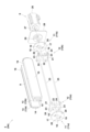
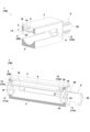
- FIG. 1 is an exploded view showing components of a rotary drive gate valve according to a first embodiment.
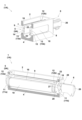
- FIG. 1 is a cross-sectional view showing a state in which the rotary drive gate valve of the first embodiment is opened;
- FIG. 1 is a cross-sectional view showing a state in which the rotary drive gate valve of the first embodiment is closed;
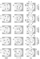
- FIG. 1 is an explanatory diagram of the operation of a valve plate unit in a rotary drive type gate valve according to the first embodiment;
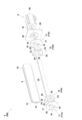
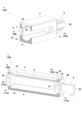
- FIG. 13 is an exploded view showing components of a rotary drive gate valve according to a second embodiment.
- FIG. 11 is a cross-sectional view showing a state in which the rotary drive gate valve of the second embodiment is opened;
- FIG. 11 is a cross-sectional view showing a state in which the rotary drive gate valve of the second embodiment is closed;
- FIG. 11 is an explanatory diagram of the operation of a valve plate unit in a rotary drive type gate valve according to the second embodiment;
- the rotary drive gate valve 1 (1A) of this embodiment is a gate valve for isolating vacuum from vacuum, or vacuum from atmosphere, in equipment for manufacturing flat panel displays and semiconductor substrates, and is used to isolate various processes in manufacturing displays and substrates.
- the valve body 2 of this rotary drive gate valve 1 (1A) is a so-called valve box type valve, and is composed of a square valve box 4 having a top plate 3, a valve plate unit 5 (5A) housed inside the valve box 4, and a drive mechanism 6 attached to the outside of the valve box 4 and driving the valve plate unit 5 (5A).
- a pair of elongated openings (first opening 7 and second opening 8) facing each other are provided on both the left and right sides of the valve box 4 to allow the substrate to pass through.
- the process chamber PC is connected to the outer wall surface of the first opening 7, and the transfer chamber TC is connected to the outer wall surface of the second opening 8.
- the substrate transported from the transfer chamber TC to the process chamber PC through the valve box 4 is placed in a sealed environment by closing the first opening 7 with the valve plate unit 5 (5A), and heat, gas, plasma, and other processing for various film formation is carried out inside the evacuated process chamber PC.
- valve plate unit 5 that selectively opens and closes the first opening 7 and the second opening 8.
- Figure 2 is an exploded view of the components omitting the top plate 3 and the valve box 4, and as shown in the figure, the valve plate unit 5 (5A) is composed of a first valve plate 9 that opens and closes the first opening 7, a second valve plate 10 that opens and closes the second opening 8, a rotating plate 11 (11a, 11b) that rotates and moves these two valve plates, and a sliding plate 12 (12a, 12b) that slides and moves each of the two valve plates.
- the first valve plate 9 and the second valve plate 10 are designed to be sized to close the first opening 7 and the second opening 8, and are formed into a rectangular shape with an arc-shaped cross section and a horizontally long plane.
- the inner surfaces of the first valve plate 9 and the second valve plate 10 are each provided with a flat mounting piece 13 (13a, 13b).
- the mounting piece 13a of the first valve plate 9 has a straight elongated hole 14 with a straight cross section that penetrates in the longitudinal direction
- the mounting piece 13b of the second valve plate 10 has a bent elongated hole 15 with a bent cross section that penetrates in the longitudinal direction.
- Gaskets 16, 16 are fitted and fixed onto the outer periphery of the first valve plate 9 and the second valve plate 10 as elastic sealants that fit closely against the opening edges of the first opening 7 and the second opening 8, respectively.
- the seal groove into which the packing 16 of the sealing material is fitted is the seal groove of a patent invention (Patent No. 5639767) held by the applicant. That is, this seal groove is formed on a flat surface and a curved surface smoothly connected to it, and has a circular cross-sectional shape with a narrowed inlet near the inlet like an inverted ⁇ shape and a wider inner part than the narrowed inlet near the inlet.
- the method of forming it is to move a groove cutter for forming a seal groove of the cross-sectional shape along the flat surface on the valve plate surface where the flat surface and the curved surface are smoothly connected, and to rotate the groove cutter around a point a predetermined distance away from the curved surface on the curved surface, so that the cross-sectional shape of the seal groove is the same on the flat surface and the curved surface.
- the rotating plate 11 is composed of a pair of circular plates 17, 17 arranged in front and behind, and a rotating shaft 18 is provided at the center of each circular plate 17.
- the circular plate 17 has arc-shaped slots 19, 19 arranged symmetrically in the circumferential direction of the rotating shaft 18, and circular shaft holes 20, 20 arranged symmetrically on the periphery of the circular plate 17.
- the sliding plate 12 is composed of a pair of square plates 21, 21 arranged in front and behind, and a shaft hole 22 is provided at the center of each square plate 21.
- the square plate 21 has two pins 23, 23 that can limit the rotation of the sliding plate 12 to 0 degrees to 90 degrees by aligning with the slot 19 and the long slot formed in the flange 28, and left and right mounting recesses 24, 24 that correspond to the mounting pieces 13.
- one shaft 25, 25 is inserted into each of the straight long hole 14 and the bent long hole 15, and both ends of the shaft 25 are fixed to the shaft holes 20, 20 of the front and rear circular plates 17, 17.
- the mounting pieces 13a, 13b are fitted and fixed into the left and right mounting recesses 24, 24 of the square plate 21, so that the first valve plate 9 and the second valve plate 10 are connected to the sliding plate 12 and integrated.
- the two pins 23, 23 of the square plate 21 are fitted into the pair of slots 19, 19 of the circular plate 17 and the long slot formed in the flange 28, respectively, and the rotating shaft 18 of the circular plate 17 is fitted into the shaft hole 22 of the square plate 21, so that the rotating plate 11 and the sliding plate 12 are connected and integrated.
- first valve plate 9, second valve plate 10, rotating plate 11, and sliding plate 12 are integrated to form the valve plate unit 5 (5A).
- a cam mechanism (Scotch yoke mechanism) is provided that converts the rotational motion of the rotating plate 11 into linear motion of the sliding plate 12 using a driving link consisting of the slot 19 of the rotating plate 11 and the shaft 25 connected to the rotating plate 11, and a driven link consisting of the straight long hole 14 of the first valve plate 9, the curved long hole 15 of the second valve plate 10, and the pin 23 of the sliding plate 12.
- the valve plate unit 5 (5A) configured as described above is rotated by a drive mechanism 6 equipped with a motor 26. That is, the output shaft 27 of the motor 26 passes through a boss hole 29 provided in the center of the flange 28 and is directly connected to the rotating shaft 18 of the right rotating plate 11b, thereby connecting the valve plate unit 5 (5A) to the motor 26.
- the motor 26 is driven to rotate the output shaft 27, the front and rear rotating plates 11a, 11b are rotated together via the rotating shaft 18, and the first valve plate 9 and second valve plate 10 connected thereto rotate about their axes, reciprocating between the open and closed positions of the opening.
- FIG. 3 shows the rotary drive gate valve 1 (1A) in an open state, FIG. 4 in a closed state, and FIG. 5 in the operation of each part that constitutes the valve plate unit 5 (5A).
- the state of the valve plate unit 5 (5A) at this time is as shown in FIG. 5(A), with the rotating plate 11, the pin 23 is positioned on a horizontal plane passing through the axis within the slot 19.
- the slide plate 12 is also tilted sideways, and the straight elongated hole 14 and curved elongated hole 15, which house the shaft 25, are positioned parallel to the horizontal plane. This is the "OPEN" position of the valve plate unit 5 (5A).
- the motor 26 of the drive mechanism 6 is driven to rotate the valve plate unit 5 (5A) from a rotation angle of 0 degrees to a rotation angle of 90 degrees.
- the rotating plate 11 is rotated as shown in FIG. 5(B), and the slide plate 12 connected to it is rotated accordingly.
- This causes the pin 23 and shaft 25 to rotate, and the first valve plate 9 and second valve plate 10 connected to the shaft 25 to rotate about their axes, moving from the open position to the closed position.
- the first valve plate 9 comes into contact with or separates from the first opening 7, and the second valve plate 10 comes into contact with or separates from the second opening 8, so that the first opening 7 and the second opening 8 can be selectively opened and closed.
- This allows the top plate 3 to be removed and the other valve plate to be taken out to the outside while maintaining the airtightness of the chamber with one of the openings closed, making it easy to perform maintenance work such as cleaning and replacing packing.
- the adoption of a rotary drive type one-sided seal mechanism can improve maintainability and reduce downtime.
- the first opening 7 and the second opening 8 are selectively opened and closed by the valve plate unit 5 (5A) having two valve plates (first valve plate 9 and second valve plate 10).
- the valve plate unit 5 having two valve plates (first valve plate 9 and second valve plate 10).
- Figures 6 to 9 show a rotary drive gate valve 1 (1B) of a second embodiment of the present invention.
- Figure 6 is an exploded view of the components omitting the top plate 3 and valve box 4, and as shown in the figure, the valve plate unit 5 (5B) of the second embodiment is composed of a first valve plate 9 that opens and closes the first opening 7, a rotating plate 11 (11a, 11b) that rotates and moves the first valve plate 9, and a sliding plate 12 (12a, 12b) that slides and moves the first valve plate 9.
- the rotating plate 11 is made up of a pair of circular plates 17, 17 arranged at the front and rear, with each circular plate 17 having a circular shaft hole 20 formed at only one location on the periphery.
- the sliding plate 12 is made up of a pair of semicircular plates 30, 30 arranged at the front and rear, with each semicircular plate 30 having an attachment recess 24 formed on only one side corresponding to the attachment piece 13. The rest of the configuration is the same as in the first embodiment, so the same members are given the same reference numerals and detailed explanations are omitted.
- a single shaft 25 is inserted into the straight long hole 14, and both ends of the shaft 25 are fixed to the shaft holes 20, 20 of the front and rear circular plates 17, 17, thereby connecting and integrating the first valve plate 9 with the rotating plate 11.
- the mounting piece 13 is fitted and fixed into the mounting recess 24 formed on one side of the semicircular plate 30, thereby connecting and integrating the first valve plate 9 with the sliding plate 12.
- the two pins 23, 23 of the semicircular plate 30 are fitted into the pair of slots 19, 19 of the circular plate 17, respectively, and the rotating shaft 18 of the circular plate 17 is fitted into the shaft hole 22 of the semicircular plate 30, thereby connecting and integrating the rotating plate 11 and the sliding plate 12.
- valve plate unit 5 of the second embodiment.
- a cam mechanism (Scotch yoke mechanism) is provided that converts the rotational motion of the rotating plate 11 into linear motion of the sliding plate 12 by a driving link consisting of the slot 19 of the rotating plate 11 and the shaft 25 connected to the rotating plate 11, and a driven link consisting of the linear elongated hole 14 of the first valve plate 9 and the pin 23 of the sliding plate 12.
- FIG. 7 shows this rotary drive gate valve 1 (1B) in an open state, FIG. 8 in a closed state, and FIG. 9 in the operation of each part that makes up the valve plate unit 5 (5B).
- the state of the valve plate unit 5 (5B) at this time is as shown in FIG. 9(A), with respect to the rotating plate 11, the pin 23 is positioned on a horizontal plane passing through the axis within the slot 19.
- the slide plate 12 is also in a state where it has been tilted straight to the side, and the straight elongated hole 14 containing the shaft 25 is positioned parallel to the horizontal plane. This is the "OPEN" position of the valve plate unit 5 (5B).
- the motor 26 of the drive mechanism 6 is driven to rotate the valve plate unit 5 (5B) from a rotation angle of 0 degrees to a rotation angle of 90 degrees.
- the rotating plate 11 is rotated as shown in FIG. 9(B), and the slide plate 12 connected to it is rotated accordingly.
- This causes the pin 23 and shaft 25 to rotate, and the first valve plate 9 connected to the shaft 25 to rotate about its axis, moving from the open position to the closed position.
- the first valve plate 9 comes into contact with or separates from the first opening 7, thereby opening and closing the first opening 7.
- the second valve plate 10 can be attached to the valve plate unit 5 (5B) instead of the first valve plate 9. This allows the top plate 3 to be removed and the other valve plate to be taken out to the outside while maintaining the airtightness of the chamber with either one of the openings closed, making it easy to perform maintenance work such as cleaning and replacing packing. In this way, the adoption of a rotary drive type one-sided seal mechanism can improve maintainability and reduce downtime.
- Rotary drive type gate valve 2 Valve body 3: Top plate 4: Valve body 5: Valve plate unit 6: Drive mechanism 7: First opening 8: Second opening 9: First valve plate 10: Second valve plate 11: Rotating plate 12: Slide plate 13: Mounting piece 14: Straight elongated hole 15: Bent elongated hole 16: Gasket 17: Circular plate 18: Rotating shaft 19: Slot 20: Shaft hole 21: Square plate 22: Shaft hole 23: Pin 24: Mounting recess 25: Shaft 26: Motor 27: Output shaft 28: Flange 29: Boss hole 30: Semicircular plate
Landscapes
- Engineering & Computer Science (AREA)
- General Engineering & Computer Science (AREA)
- Mechanical Engineering (AREA)
- Sliding Valves (AREA)
- Taps Or Cocks (AREA)
Priority Applications (3)
| Application Number | Priority Date | Filing Date | Title |
|---|---|---|---|
| JP2023526616A JP7296083B1 (ja) | 2023-01-30 | 2023-01-30 | 回転駆動式ゲートバルブ |
| KR1020257024367A KR20250123209A (ko) | 2023-01-30 | 2023-01-30 | 회전 구동식 게이트 밸브 |
| PCT/JP2023/002807 WO2024161444A1 (ja) | 2023-01-30 | 2023-01-30 | 回転駆動式ゲートバルブ |
Applications Claiming Priority (1)
| Application Number | Priority Date | Filing Date | Title |
|---|---|---|---|
| PCT/JP2023/002807 WO2024161444A1 (ja) | 2023-01-30 | 2023-01-30 | 回転駆動式ゲートバルブ |
Publications (1)
| Publication Number | Publication Date |
|---|---|
| WO2024161444A1 true WO2024161444A1 (ja) | 2024-08-08 |
Family
ID=86772826
Family Applications (1)
| Application Number | Title | Priority Date | Filing Date |
|---|---|---|---|
| PCT/JP2023/002807 Ceased WO2024161444A1 (ja) | 2023-01-30 | 2023-01-30 | 回転駆動式ゲートバルブ |
Country Status (3)
| Country | Link |
|---|---|
| JP (1) | JP7296083B1 (cg-RX-API-DMAC7.html) |
| KR (1) | KR20250123209A (cg-RX-API-DMAC7.html) |
| WO (1) | WO2024161444A1 (cg-RX-API-DMAC7.html) |
Citations (8)
| Publication number | Priority date | Publication date | Assignee | Title |
|---|---|---|---|---|
| JP2006292107A (ja) * | 2005-04-12 | 2006-10-26 | Tokyo Electron Ltd | ゲートバルブ装置及び処理システム |
| JP2006329361A (ja) * | 2005-05-27 | 2006-12-07 | Kyocera Corp | バルブ |
| WO2010113891A1 (ja) * | 2009-03-31 | 2010-10-07 | 東京エレクトロン株式会社 | ゲートバルブ装置およびこれを備える基板処理装置 |
| WO2014087789A1 (ja) * | 2012-12-04 | 2014-06-12 | 株式会社キッツエスシーティー | バタフライ式圧力制御バルブ |
| JP5639767B2 (ja) * | 2010-02-26 | 2014-12-10 | 入江工研株式会社 | シール溝 |
| WO2018168878A1 (ja) * | 2017-03-16 | 2018-09-20 | 日新電機株式会社 | ゲートバルブ装置 |
| CN109210228A (zh) * | 2018-11-07 | 2019-01-15 | 成都乘风阀门有限责任公司 | 将军阀 |
| JP2019090522A (ja) * | 2017-11-17 | 2019-06-13 | 株式会社ダンレイ | 流路切換弁 |
Family Cites Families (2)
| Publication number | Priority date | Publication date | Assignee | Title |
|---|---|---|---|---|
| JP2996915B2 (ja) | 1996-06-03 | 2000-01-11 | 入江工研株式会社 | 無しゅう動真空ゲートバルブ |
| KR101317696B1 (ko) | 2011-12-13 | 2013-10-15 | (주)시스콤 | 게이트 밸브의 벨로우즈 보호 구조 |
-
2023
- 2023-01-30 JP JP2023526616A patent/JP7296083B1/ja active Active
- 2023-01-30 WO PCT/JP2023/002807 patent/WO2024161444A1/ja not_active Ceased
- 2023-01-30 KR KR1020257024367A patent/KR20250123209A/ko active Pending
Patent Citations (8)
| Publication number | Priority date | Publication date | Assignee | Title |
|---|---|---|---|---|
| JP2006292107A (ja) * | 2005-04-12 | 2006-10-26 | Tokyo Electron Ltd | ゲートバルブ装置及び処理システム |
| JP2006329361A (ja) * | 2005-05-27 | 2006-12-07 | Kyocera Corp | バルブ |
| WO2010113891A1 (ja) * | 2009-03-31 | 2010-10-07 | 東京エレクトロン株式会社 | ゲートバルブ装置およびこれを備える基板処理装置 |
| JP5639767B2 (ja) * | 2010-02-26 | 2014-12-10 | 入江工研株式会社 | シール溝 |
| WO2014087789A1 (ja) * | 2012-12-04 | 2014-06-12 | 株式会社キッツエスシーティー | バタフライ式圧力制御バルブ |
| WO2018168878A1 (ja) * | 2017-03-16 | 2018-09-20 | 日新電機株式会社 | ゲートバルブ装置 |
| JP2019090522A (ja) * | 2017-11-17 | 2019-06-13 | 株式会社ダンレイ | 流路切換弁 |
| CN109210228A (zh) * | 2018-11-07 | 2019-01-15 | 成都乘风阀门有限责任公司 | 将军阀 |
Also Published As
| Publication number | Publication date |
|---|---|
| JPWO2024161444A1 (cg-RX-API-DMAC7.html) | 2024-08-08 |
| JP7296083B1 (ja) | 2023-06-22 |
| KR20250123209A (ko) | 2025-08-14 |
Similar Documents
| Publication | Publication Date | Title |
|---|---|---|
| US6095741A (en) | Dual sided slot valve and method for implementing the same | |
| JP3837391B2 (ja) | ゲートバルブ | |
| US7575220B2 (en) | Curved slit valve door | |
| JPH0842715A (ja) | 無しゅう動真空ゲートバルブ | |
| JP2004502105A5 (cg-RX-API-DMAC7.html) | ||
| JP2018501443A (ja) | 真空チャンバのチャンバ壁内のチャンバ開口を閉鎖するドア | |
| US20090189107A1 (en) | Valve device | |
| JP4225647B2 (ja) | ゲートバルブ | |
| JPH0599348A (ja) | ゲートバルブ | |
| US7270311B1 (en) | Pendulum gate valve | |
| JP6508895B2 (ja) | マルチポート弁アセンブリを備えるプラズマ処理装置 | |
| JP2005320622A (ja) | 交換可能メンテナンス弁 | |
| US7296783B2 (en) | Vacuum processing apparatus | |
| JP7296083B1 (ja) | 回転駆動式ゲートバルブ | |
| JP4728602B2 (ja) | 真空室に基板を装填するためのロードロック装置 | |
| JP4432728B2 (ja) | 真空処理装置 | |
| KR20230133872A (ko) | 밸브, 특히 진공 밸브 | |
| JPH05306779A (ja) | ゲート弁 | |
| JP2000028013A (ja) | ゲート式真空遮断弁 | |
| KR102656261B1 (ko) | 플랩 푸쉬 밸브 | |
| CN114877102B (zh) | 一种用于气动阀门定位器的大流量阀体 | |
| CN220610269U (zh) | 一种采用真空技术的新材料生产装置 | |
| CN2521225Y (zh) | 真空腔的密闭装置 | |
| TWI484531B (zh) | 閥門總成以及閥門 | |
| JPS6037139A (ja) | ウェ−ハ移送経路におけるゲ−トバルブ機構 |
Legal Events
| Date | Code | Title | Description |
|---|---|---|---|
| WWE | Wipo information: entry into national phase |
Ref document number: 2023526616 Country of ref document: JP |
|
| 121 | Ep: the epo has been informed by wipo that ep was designated in this application |
Ref document number: 23919589 Country of ref document: EP Kind code of ref document: A1 |
|
| ENP | Entry into the national phase |
Ref document number: 1020257024367 Country of ref document: KR Free format text: ST27 STATUS EVENT CODE: A-0-1-A10-A15-NAP-PA0105 (AS PROVIDED BY THE NATIONAL OFFICE) |
|
| WWE | Wipo information: entry into national phase |
Ref document number: 1020257024367 Country of ref document: KR |
|
| WWP | Wipo information: published in national office |
Ref document number: 1020257024367 Country of ref document: KR |
|
| NENP | Non-entry into the national phase |
Ref country code: DE |
|
| 122 | Ep: pct application non-entry in european phase |
Ref document number: 23919589 Country of ref document: EP Kind code of ref document: A1 |