WO2024154502A1 - カテーテル - Google Patents
カテーテル Download PDFInfo
- Publication number
- WO2024154502A1 WO2024154502A1 PCT/JP2023/045058 JP2023045058W WO2024154502A1 WO 2024154502 A1 WO2024154502 A1 WO 2024154502A1 JP 2023045058 W JP2023045058 W JP 2023045058W WO 2024154502 A1 WO2024154502 A1 WO 2024154502A1
- Authority
- WO
- WIPO (PCT)
- Prior art keywords
- catheter
- shaft
- coil
- tip
- rear end
- Prior art date
- Legal status (The legal status is an assumption and is not a legal conclusion. Google has not performed a legal analysis and makes no representation as to the accuracy of the status listed.)
- Ceased
Links
Images


Classifications
-
- A—HUMAN NECESSITIES
- A61—MEDICAL OR VETERINARY SCIENCE; HYGIENE
- A61B—DIAGNOSIS; SURGERY; IDENTIFICATION
- A61B8/00—Diagnosis using ultrasonic, sonic or infrasonic waves
- A61B8/12—Diagnosis using ultrasonic, sonic or infrasonic waves in body cavities or body tracts, e.g. by using catheters
-
- A—HUMAN NECESSITIES
- A61—MEDICAL OR VETERINARY SCIENCE; HYGIENE
- A61M—DEVICES FOR INTRODUCING MEDIA INTO, OR ONTO, THE BODY; DEVICES FOR TRANSDUCING BODY MEDIA OR FOR TAKING MEDIA FROM THE BODY; DEVICES FOR PRODUCING OR ENDING SLEEP OR STUPOR
- A61M25/00—Catheters; Hollow probes
Definitions
- the present invention relates to a catheter.
- Patent Document 1 describes a catheter equipped with an ultrasonic sensor.
- the ultrasonic sensor is connected to a drive shaft, and is operated while the drive shaft is rotated by a motor or the like.
- the signal wire connected to the sensor can be compressed while the catheter is in use, making it difficult to obtain accurate information. Also, when obtaining images of the inside of the body using an ultrasonic sensor or the like, distortion of the images can occur when the drive shaft inserted into the body cannot rotate steadily, resulting in "Non-Uniformed-Rotational-Distortion (NURD)."
- NURD Non-Uniformed-Rotational-Distortion
- the present invention aims to provide a catheter that can accommodate a sensor and obtain more accurate information from within the body.
- it aims to provide a catheter that can obtain ultrasound images from within the body with little distortion.
- the present invention has been made to solve at least some of the problems described above, and can be realized in the following form.
- One aspect of the present invention is a catheter comprising: a first shaft having a lumen capable of housing a sensor inside the first shaft for acquiring information from within the body; a hollow second shaft arranged along the first shaft; and a coil arranged inside the first shaft and extending along the lumen, the tip of the coil being located rearward of the tip of the lumen in the longitudinal direction of the catheter.
- the coil provided on the first shaft can prevent the lumen from narrowing while the catheter is in use. This can reduce the possibility that, for example, a signal line connected to a sensor housed in the lumen will be compressed, or that rotation of the drive shaft will be hindered.
- the sensor can be operated in a section where no coil is provided. This can reduce the possibility that, for example, ultrasound will be obstructed by the coil when scanning with ultrasound.
- the rear end of the second shaft may be located between the front end of the coil and the rear end of the coil in the longitudinal direction of the catheter.
- the position of the rear end of the second shaft in the longitudinal direction corresponds to the middle part of the coil provided on the first shaft. This allows the coil to be provided in front of and behind the rear end of the second shaft, reducing the occurrence of bending or creased catheters near the rear end of the second shaft.
- the second shaft is formed from a resin tube, and in the longitudinal direction of the catheter, the resin tube may have a step portion at the same position as the tip of the coil or at a position rearward of the tip of the coil where the thickness changes so that the thickness at the tip side is thinner than the thickness at the rear end side.
- the thickness of the resin tube forming the second shaft at the portion located closer to the tip than the coil is thinner, which reduces the amount of interference caused by the resin tube with ultrasound and other signals emitted by the sensor operating at the tip of the catheter.
- the second shaft is formed of a resin tube, and the tip of the resin tube may be located at the same position as the tip of the coil or further back than the tip of the coil in the longitudinal direction of the catheter.
- the resin tube that forms the second shaft is not located further distal than the coil, which reduces the possibility that the resin tube will interfere with ultrasound waves and other signals emitted from a sensor operating at the distal end of the catheter.
- the coil may be formed of wire wound in a spiral shape, and the outer diameter of the wire at the tip end of the coil may be smaller than the outer diameter of the wire at the rear end of the coil.
- the outer diameter of the coil wire is smaller toward the tip, improving the flexibility of the catheter at its tip.
- the present invention can be realized in various forms, such as a guidewire, a method for manufacturing a guidewire, a method for manufacturing a catheter, an endoscope, a dilator, etc.
- FIG. 1 is an explanatory diagram illustrating an example of the overall configuration of a catheter according to a first embodiment.
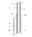
- FIG. 2 is an explanatory diagram illustrating a longitudinal cross section of the tip and rear end portions of a catheter.
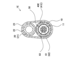
- FIG. 3 is an explanatory diagram illustrating a cross section taken along the line AA in FIG. 2.
- FIG. 2 is an explanatory diagram illustrating a longitudinal cross section of the tip of a catheter.
- FIG. 13 is an explanatory diagram illustrating a curved state of a catheter without a coil.
- FIG. 4 is an explanatory diagram illustrating a curved state of the catheter of the first embodiment.
- 11 is an explanatory diagram illustrating a vertical cross section of a rear end portion of a second shaft.
- FIG. 1 is an explanatory diagram illustrating an example of the overall configuration of a catheter according to a first embodiment.
- FIG. 2 is an explanatory diagram illustrating a longitudinal cross section of the tip and rear end portions of a catheter.
- FIG. 1 is an explanatory diagram illustrating a change in bending rigidity of a catheter and a coil.
- FIG. 13 is an explanatory diagram illustrating a catheter curved due to the shape memory properties of the coil.
- 13 is an explanatory diagram illustrating a longitudinal cross section of the tip of a catheter according to a second embodiment.
- FIG. 13 is an explanatory diagram illustrating a longitudinal cross section of the tip of a catheter according to a third embodiment.
- FIG. 13 is an explanatory diagram illustrating a longitudinal cross section of the tip of a catheter according to a fourth embodiment.
- FIG. FIG. 13 is an explanatory diagram illustrating a cross section of a catheter of modified example 1.
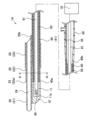
- Fig. 1 is an explanatory diagram illustrating the overall configuration of a catheter 1A of the first embodiment.
- Fig. 2 is an explanatory diagram illustrating longitudinal cross sections of the tip and rear end portions of the catheter 1A.
- the end portion of each component of the catheter 1A located on the tip side will be referred to as the "tip portion”, and the portion including the “tip portion” and extending from the tip to the middle toward the rear end will be referred to as the "tip portion”.
- the end portion of each component located on the rear end side will be referred to as the "rear end”
- the portion including the "rear end” and extending from the rear end to the middle toward the tip side will be referred to as the "rear end portion”.
- Catheter 1A is a medical device that is inserted into blood vessels, the digestive tract, etc., and is used for treatment and diagnosis of the human body.
- the catheter 1A comprises a first shaft 10, a second shaft 20, a connector 30, a coil 40, and an inner shaft 50.
- a drive shaft 61 having a sensor 60 at its tip is disposed inside the first shaft 10. The base end of the drive shaft 61 is connected to the console 70.
- the first shaft 10 is a hollow member that extends in the longitudinal direction of the catheter 1A and has a lumen 11.
- the lumen 11 is a space that extends in the longitudinal direction of the catheter 1A and is formed by being surrounded by the inner wall of the first shaft 10.
- the tip of the first shaft 10 is not open, and the tip of the lumen 11 does not communicate with the outside of the catheter 1A.
- the second shaft 20 is a hollow member extending in the longitudinal direction of the catheter 1A, and is formed from a resin tube 21, a resin tube 22, and a resin tube 23.
- the resin tube 21 is disposed on the innermost side, and the outer circumference of the resin tube 21 is covered by the resin tube 22.
- a part of the resin tube 22 and a part of the first shaft 10 are integrally covered by the resin tube 23.
- the first shaft 10 and the second shaft 20 are fixed by the resin tube 23.
- the resin tube 21 extends from the tip to the rear end of the catheter 1A. From the tip side of the catheter 1A, the tip of the resin tube 21, the tip 22a of the resin tube 22, and the tip of the resin tube 23 are provided in this order, spaced apart from each other.
- a step portion 25 is formed at the position of the tip 22a of the resin tube 22. Details of the step portion 25 will be described later using FIG. 4. Details of the rear end 20b of the second shaft 20 will be described later using FIG. 7.
- a lumen 24 is formed inside the resin tube 21.
- the lumen 24 is a space that extends in the longitudinal direction of the second shaft 20 and is formed by being surrounded by the inner wall of the resin tube 21.
- the front and rear ends of the resin tube 21 are open, and the front and rear ends of the lumen 24 communicate with the outside of the catheter 1A. This makes it possible to insert a guidewire (not shown) or the like into the lumen 24, and to insert the catheter 1A into the body via the guidewire.
- the method for fixing the first shaft 10 and the second shaft 20 is not particularly limited, but may be by using a resin tube 23 as described above, or may be by heat welding or adhesive.
- the material of the first shaft 10 and the second shaft 20 is not particularly limited, but examples that can be used include nylon resins such as polyamide, polyolefins such as polyethylene, polypropylene, and ethylene-propylene copolymers, polyesters such as polyethylene terephthalate, thermoplastic resins such as polyvinyl chloride, ethylene-vinyl acetate copolymers, cross-linked ethylene-vinyl acetate copolymers, and polyurethane, polyamide elastomers, polyolefin elastomers, polyurethane elastomers, silicone rubber, and latex rubber.
- nylon resins such as polyamide
- polyolefins such as polyethylene, polypropylene, and ethylene-propylene copolymers
- polyesters such as polyethylene terephthalate
- thermoplastic resins such as polyvinyl chloride, ethylene-vinyl acetate copolymers, cross-linked ethylene-vinyl acetate copoly
- the connector 30 is a member for connecting the catheter 1A to other medical devices such as a syringe (not shown).
- the coil 40 is a hollow member provided inside the first shaft 10, and is formed from a wire 41 wound in a spiral shape.
- the tip 40a of the coil 40 is provided rearward of the tip 11a of the lumen 11, and the rear end 40b of the coil 40 extends to the connector 30.
- the rear end 40b of the coil 40 is electrically connected to a cable 42, which is electrically connected to a current-carrying device (not shown) included in the console 70. Details of the coil 40 will be described later.
- the inner shaft 50 is a hollow resin member provided inside the coil 40, and is provided so as to cover the inner circumference of the coil 40. As a result, the surface of the inner circumference of the coil 40 is not exposed to the lumen 11.
- the material of the inner shaft 50 is not particularly limited, but for example, PTFE, etc. can be used.
- the sensor 60 is a device with the function of acquiring information from within the body and converting it into a signal.
- the sensor 60 is an ultrasonic sensor, and is composed of an ultrasonic transducer and a housing (not shown).
- the sensor 60 is provided at the tip of a drive shaft 61 (described later), and transmits ultrasonic waves toward the body wall and receives the reflected waves from the body wall or the like.
- the sensor 60 is an ultrasonic sensor, but the sensor 60 is not limited to an ultrasonic sensor, and any sensor generally used to acquire biological information can be used.
- the sensor 60 may be one for acquiring the position of the catheter 1A within the body, or one for measuring blood pressure.
- the drive shaft 61 is a long member that is rotatable around its long axis.
- the drive shaft 61 is connected to a motor included in the console 70, and is rotated in response to the operation of a user such as a doctor.
- a user such as a doctor.
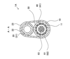
- FIG. 3 is an explanatory diagram illustrating the A-A cross section of the catheter 1A in FIG. 2.
- the drive shaft 61 is formed by winding a number of metal wires 62 in a spiral shape.
- a cable 63 is provided inside the drive shaft 61.
- the cable 63 is electrically connected to the sensor 60 (FIG. 2) and is used to transmit information from the sensor 60 to the console 70 (FIG. 2).
- the console 70 (Figs. 1 and 2) is a device for controlling the sensor 60 and drive shaft 61 and generating images. Specifically, the console 70 transmits ultrasonic waves from the sensor 60 in response to the operation of a user such as a doctor, and generates images of the inside of the body based on information about the reflected waves received by the sensor 60. The console 70 also controls the longitudinal movement and rotation of the drive shaft 61 in response to the operation of the user of the catheter 1A.
- the coil 40 is formed by winding a plurality of wires 41 in a spiral shape.
- the coil 40 is disposed so as to surround the drive shaft 61.
- the drive shaft 61 is disposed inside the coil 40.
- the coil 40 is embedded inside the first shaft 10.
- the cross section of the wires 41 is substantially rectangular, and is formed by being surrounded by short sides and long sides that are longer than the short sides.
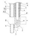
- FIG. 4 is an explanatory diagram illustrating a longitudinal cross section of the tip of the catheter 1A.
- the tip 40a of the coil 40 is located rearward of the tip 11a of the lumen 11. This forms a section S in the first shaft 10 between the tip 11a of the lumen 11 and the tip 40a of the coil 40 where the coil 40 is not provided.
- section S except for the second shaft 20, only the resin that constitutes the wall surface of the first shaft 10 is provided.
- the sensor 60 can scan with ultrasound while moving in the longitudinal direction D within the lumen 11 in section S.
- the coil 40 is composed of three types of wires 41 with different outer diameters.
- the wires 41 are configured so that the outer diameter gradually decreases toward the tip. Specifically, the outer diameter Od1 (the size of the wires 41 in the radial direction of the coil 40) of the wires 41 of the coil 40 provided at the tip end is smaller than the outer diameter Od2 of the wires 41 provided at the rear end.
- the cross section of the wires 41 is rectangular, and the thickness of the rectangle is the outer diameter (Od1, Od2) of the wires 41.
- the cross section of the wires 41 is a circle close to a perfect circle, the diameter of the circle is the outer diameter of the wires 41.
- the material of the coil 40 is not particularly limited, but examples include stainless steel (SUS302, SUS304, SUS316, etc.), superelastic alloys such as Ni-Ti alloys, piano wire, nickel-chromium alloys, cobalt alloys, tungsten, platinum, etc.
- step portion 25 As shown in FIG. 4, the tip 22a of the resin tube 22 covering the second shaft 20 is provided at approximately the same position in the longitudinal direction as the tip 40a of the coil 40. As a result, a step portion 25 where the thickness of the second shaft 20 changes is formed at the position of the tip 22a of the resin tube 22.
- the second shaft 20 has a portion with a thin thickness on the tip side and a portion with a thick thickness on the rear end side of the step portion 25.
- the thickness t1 of the portion formed only by the resin tube 21 on the tip side of the step portion 25 is smaller than the thickness t2 of the portion where the resin tube 21 and the resin tube 22 overlap on the rear end side of the step portion 25.
- the tip 22a of the resin tube 22 is provided at approximately the same position in the longitudinal direction as the tip 40a of the coil 40, but the tip 22a of the resin tube 22 may be provided on the rear end side of the tip 40a of the coil 40 as in a second embodiment described later.
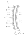
- FIG. 5 is an explanatory diagram illustrating a curved state of the catheter 1Z without the coil 40 as a comparative example.
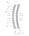
- FIG. 6 is an explanatory diagram illustrating a curved state of the catheter 1A of the first embodiment.
- the catheter 1Z of the comparative example is different from the catheter 1A of the first embodiment in that it does not have the coil 40.
- the first shaft 10Z, lumen 11Z, inner shaft 50Z, and drive shaft 61Z of the catheter 1Z have the same configuration as the first shaft 10, lumen 11, inner shaft 50, and drive shaft 61 of the catheter 1A.
- a pressure F is applied from the outside to the first shaft 10Z.
- the first shaft 10Z may be crushed, and the diameter of the lumen 11Z may be narrowed.
- the drive shaft 61Z disposed in the lumen 11Z rotates in the R direction around its long axis, but if the drive shaft 61Z comes into contact with the inner wall of the first shaft 10Z, the rotation of the drive shaft 61Z is hindered and steady rotation may not be possible.
- the catheter 1A of the first embodiment is provided with a coil 40 on the first shaft 10, which improves the durability of the first shaft 10 against external pressure and reduces the possibility of the first shaft 10 collapsing and causing the inner wall of the first shaft 10 to come into contact with the drive shaft 61.
- Fig. 7 is an explanatory diagram illustrating a vertical cross section of the rear end portion of the second shaft 20.
- the tip 40a of the coil 40 is provided on the tip side of the rear end 20b of the second shaft 20, and the rear end 40b of the coil 40 extends to the connector 30.
- the rear end 20b of the second shaft 20 is located between the tip 40a of the coil 40 and the rear end 40b of the coil 40.
- the coil 40 is provided in the first shaft 10 in the portions in front of and behind the rear end 20b of the second shaft 20.
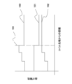
- Fig. 8 is an explanatory diagram illustrating the change in bending stiffness of the catheter 1A and the coil 40.
- Fig. 8 shows the following three bending stiffnesses on the proximal end side of the tip 40a of the coil 40:
- Overall bending stiffness of the catheter 1A 100 Bending rigidity 101 of the portions of the catheter 1A other than the coil 40 (the first shaft 10, the second shaft 20, etc.) Bending rigidity 102 of the coil 40
- the bending stiffness 101 of the catheter 1A other than the coil 40 decreases at position 103 of the rear end 20b of the second shaft 20.
- the bending stiffness 100 of the entire catheter 1A decreases in the rate of decrease in bending stiffness at position 103 by the amount to which bending stiffness 102 of the coil 40 is added.
- the outer diameter of the wire 41 is large and the part of the coil 40 with the greatest bending stiffness is disposed at position 103, so that the rate of decrease in bending stiffness at position 103 decreases.
- the coil 40 reinforces the catheter 1A near the rear end 20b of the second shaft 20, where the bending stiffness changes abruptly.
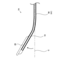
- FIG. 9 is an explanatory diagram illustrating a catheter 1A curved due to the shape memory properties of the coil 40.
- the wire 41 of the coil 40 in this embodiment is formed of a Ni-Ti alloy that has been subjected to a shape memory treatment.
- the shape memory treatment here refers to bending the coil 40, which is made of a superelastic alloy, into a desired shape while heating it to a temperature above its transformation point, and then cooling it to memorize the curved shape.
- FIG. 9 illustrates a catheter 1A curved at an arbitrary angle relative to the longitudinal axis C of the catheter 1A.
- a current is passed through the coil 40 via a cable 42 (FIG. 2) using a current supply device or the like incorporated in the console 70 to heat the coil 40.
- the catheter 1A is deformed into the memorized curved shape.
- the first shaft 10 has a coil 40. This can prevent the first shaft 10 from being crushed due to application of external pressure to the first shaft 10, and by preventing compression of the cable 63 that transmits the information received by the sensor 60, it becomes easier to obtain accurate information.
- NURD can be suppressed by reducing the possibility that the rotation of the drive shaft 61 will be hindered due to contact between the inner wall of the first shaft 10 and the drive shaft 61. This makes it possible to obtain ultrasound images of the inside of the body with less distortion.
- the tip 40a of the coil 40 is located rearward of the tip 11a of the lumen 11.
- the sensor 60 can be operated in a section S where the coil 40 is not provided. This reduces the possibility that the coil 40 will interfere with the ultrasound when scanning, for example, and allows clearer ultrasound images of the inside of the body to be obtained.
- the second shaft 20 has a step portion 25, and the thickness t1 of the second shaft 20 on the tip side of the step portion 25 is thinner than the thickness t2 of the second shaft 20 on the rear side of the step portion 25.
- the portion of the second shaft 20 that overlaps with the section S in the longitudinal direction is composed only of the resin tube 21. Therefore, the amount of interference with the ultrasound by the resin tube when scanning the ultrasound can be reduced. In addition, the flexibility of the tip portion of the catheter 1A can be improved.
- the rear end 20b of the second shaft 20 is located between the tip 40a and rear end 40b of the coil 40. Near the rear end 20b of the second shaft 20, a sudden change in the bending stiffness of the catheter 1A occurs, but by arranging the coil 40 near the rear end 20b of the second shaft 20, it is possible to increase the bending stiffness of the catheter 1A near the rear end 20b. This makes it possible to prevent the catheter 1A from breaking or bending near the rear end 20b of the second shaft 20.
- the outer diameter of the wire 41 at the tip end of the coil 40 is smaller than the outer diameter of the wire 41 at the rear end of the coil 40. This improves the flexibility of the tip end of the catheter 1A.
- the coil 40 is made of a shape memory alloy, so that the coil 40 can be heated and deformed into a memorized curved shape while the catheter 1A is in use. This makes it easier to insert the catheter 1A into curved blood vessels, which previously made it difficult to insert the catheter 1A. It also makes it easier to remove the catheter 1A that has become stuck inside the body wall and cannot be removed.
- Second Embodiment 10 is an explanatory diagram illustrating a longitudinal section of the tip of a catheter 1B of the second embodiment.
- the catheter 1B of the second embodiment differs from the catheter 1A of the first embodiment in that a step portion 25B is located closer to the rear end than the tip 40a of the coil 40.
- a description of the points of the second embodiment that are common to the first embodiment will be omitted.
- the tip 22a of the resin tube 22 of the catheter 1B is located further rearward than the tip 40a of the coil 40 in the longitudinal direction.
- the step portion 25B is also located further rearward than the tip 40a of the coil 40.
- the portion of the second shaft 20B that overlaps with section S in the longitudinal direction is composed only of the resin tube 21. This reduces the possibility that the coil 40 will interfere with the ultrasound when scanning the ultrasound. In addition, the flexibility of the tip of the catheter 1B can be improved.
- Third Embodiment 11 is an explanatory diagram illustrating a longitudinal section of the tip of a catheter 1C of the third embodiment.
- the catheter 1C of the third embodiment differs from the catheter 1A of the first embodiment in that the tip 20a of the second shaft 20C is located at substantially the same position as the tip 40a of the coil 40, and further includes a third shaft 26.
- a description of the points of the third embodiment that are common to the first embodiment will be omitted.
- the catheter 1C has a second shaft 20C and a third shaft 26.
- the second shaft 20C and the third shaft 26 are arranged so as to be coaxial, and the third shaft 26 is arranged on the tip side of the second shaft 20.
- the third shaft 26 is joined to the first shaft 10 by a joint 27.
- the tip 20a of the second shaft 20C is arranged at approximately the same position as the tip 40a of the coil 40 in the longitudinal direction, and the rear end 26b of the third shaft 26 is arranged at approximately the same position as the tip 11a of the lumen 11 of the first shaft 10.
- the tip 20a of the second shaft 20C and the rear end 26b of the third shaft 26 are arranged at a distance from each other, and no resin tube is provided between them.
- neither the second shaft 20C nor the third shaft 26 is provided in the portion overlapping the section S in the longitudinal direction.
- neither the second shaft 20C nor the third shaft 26 is provided in the portion of the catheter 1C that overlaps with the section S of the first shaft 10 in the longitudinal direction. Therefore, it is possible to prevent the resin tube from interfering with the ultrasound when scanning with the ultrasound.
- Fourth Embodiment 12 is an explanatory diagram illustrating a longitudinal section of the tip of a catheter 1D of the fourth embodiment.
- the catheter 1D of the fourth embodiment differs from the catheter 1C of the third embodiment in that the tip 20a of the second shaft 20D is located closer to the rear end than the tip 40a of the coil 40.
- a description of the points of the fourth embodiment that are common to the third embodiment will be omitted.
- the tip 20a of the second shaft 20D of the catheter 1D is located further rearward than the tip 40a of the coil 40 in the longitudinal direction, and the rear end 26b of the third shaft 26 is located at approximately the same position as the tip 11a of the lumen 11 of the first shaft 10.
- the tip 20a of the second shaft 20D and the rear end 26b of the third shaft 26 are spaced apart, and no plastic tube is provided between them.
- neither the second shaft 20D nor the third shaft 26 is provided in the portion that overlaps with section S in the longitudinal direction.
- neither the second shaft 20D nor the third shaft 26 is provided in the portion of the catheter 1D that overlaps with the section S of the first shaft 10 in the longitudinal direction. Therefore, it is possible to prevent the resin tube from interfering with the ultrasound when scanning with the ultrasound.
- Fig. 13 is an explanatory diagram illustrating a cross section of a catheter 1E of Modification 1.
- the cross section of the coil 40 is rectangular, but it does not have to be rectangular.
- it may be circular like the coil 40E shown in Fig. 13, or it may be square or trapezoidal.
- the second shaft (20, 20B, 20C, 20D) is formed of the resin tube 21, the resin tube 22, and the resin tube 23, but it does not have to be formed of these resin tubes (21, 22, 23).
- the step portion 25 can be provided by forming a thin-walled portion at the tip portion of the resin tube 21.
Landscapes
- Health & Medical Sciences (AREA)
- Life Sciences & Earth Sciences (AREA)
- Animal Behavior & Ethology (AREA)
- Biophysics (AREA)
- Veterinary Medicine (AREA)
- Public Health (AREA)
- General Health & Medical Sciences (AREA)
- Engineering & Computer Science (AREA)
- Biomedical Technology (AREA)
- Heart & Thoracic Surgery (AREA)
- Pathology (AREA)
- Molecular Biology (AREA)
- Surgery (AREA)
- Medical Informatics (AREA)
- Radiology & Medical Imaging (AREA)
- Physics & Mathematics (AREA)
- Nuclear Medicine, Radiotherapy & Molecular Imaging (AREA)
- Pulmonology (AREA)
- Anesthesiology (AREA)
- Hematology (AREA)
- Media Introduction/Drainage Providing Device (AREA)
Applications Claiming Priority (2)
| Application Number | Priority Date | Filing Date | Title |
|---|---|---|---|
| JP2023-004291 | 2023-01-16 | ||
| JP2023004291A JP2024100348A (ja) | 2023-01-16 | 2023-01-16 | カテーテル |
Publications (1)
| Publication Number | Publication Date |
|---|---|
| WO2024154502A1 true WO2024154502A1 (ja) | 2024-07-25 |
Family
ID=91955751
Family Applications (1)
| Application Number | Title | Priority Date | Filing Date |
|---|---|---|---|
| PCT/JP2023/045058 Ceased WO2024154502A1 (ja) | 2023-01-16 | 2023-12-15 | カテーテル |
Country Status (2)
| Country | Link |
|---|---|
| JP (1) | JP2024100348A (enExample) |
| WO (1) | WO2024154502A1 (enExample) |
Citations (4)
| Publication number | Priority date | Publication date | Assignee | Title |
|---|---|---|---|---|
| JP2004130110A (ja) * | 2002-08-27 | 2004-04-30 | Terumo Corp | カテーテル |
| JP2007000358A (ja) * | 2005-06-23 | 2007-01-11 | Pura Giken:Kk | カテーテル |
| JP2012179255A (ja) * | 2011-03-01 | 2012-09-20 | Terumo Corp | カテーテル |
| JP2018157913A (ja) * | 2017-03-22 | 2018-10-11 | テルモ株式会社 | 医療用デバイス |
-
2023
- 2023-01-16 JP JP2023004291A patent/JP2024100348A/ja active Pending
- 2023-12-15 WO PCT/JP2023/045058 patent/WO2024154502A1/ja not_active Ceased
Patent Citations (4)
| Publication number | Priority date | Publication date | Assignee | Title |
|---|---|---|---|---|
| JP2004130110A (ja) * | 2002-08-27 | 2004-04-30 | Terumo Corp | カテーテル |
| JP2007000358A (ja) * | 2005-06-23 | 2007-01-11 | Pura Giken:Kk | カテーテル |
| JP2012179255A (ja) * | 2011-03-01 | 2012-09-20 | Terumo Corp | カテーテル |
| JP2018157913A (ja) * | 2017-03-22 | 2018-10-11 | テルモ株式会社 | 医療用デバイス |
Also Published As
| Publication number | Publication date |
|---|---|
| JP2024100348A (ja) | 2024-07-26 |
Similar Documents
| Publication | Publication Date | Title |
|---|---|---|
| US5306245A (en) | Articulating device | |
| US5546947A (en) | Ultrasonic endoprobe | |
| US5108411A (en) | Flexible catheter drive cable | |
| US6485457B1 (en) | Catheter | |
| JPH10500584A (ja) | カテーテル用の改良型追跡先端部 | |
| JP7528110B2 (ja) | 医療器具セット及び管状部材 | |
| JP4276544B2 (ja) | 可撓性を調節可能なガイドワイヤ | |
| KR20200071749A (ko) | 의료용 튜브 | |
| JP3775831B2 (ja) | カテーテルチューブ | |
| JP2004283461A (ja) | 先端偏向操作可能カテーテル | |
| JP3497875B2 (ja) | 体腔内超音波プローブ | |
| JPH0928664A (ja) | カテーテルチューブ | |
| JPH1057500A (ja) | 医療用チューブ | |
| JPH09266881A (ja) | カテーテルチューブ | |
| WO2024154502A1 (ja) | カテーテル | |
| JP7618513B2 (ja) | 画像診断用カテーテル | |
| JP4323191B2 (ja) | カテーテル | |
| JP3754500B2 (ja) | 超音波カテーテル | |
| US20240156347A1 (en) | Image diagnosis catheter | |
| JP2000189517A (ja) | 超音波カテ―テル | |
| JP6031183B2 (ja) | ポリマ層を備えたセンサ・ガイド・ワイヤ | |
| US20230218267A1 (en) | Drive shaft and image diagnosis catheter | |
| JP3280485B2 (ja) | 体腔内超音波プローブ | |
| JP3889869B2 (ja) | 超音波プローブ | |
| JP4280112B2 (ja) | 超音波カテーテル |
Legal Events
| Date | Code | Title | Description |
|---|---|---|---|
| 121 | Ep: the epo has been informed by wipo that ep was designated in this application |
Ref document number: 23917713 Country of ref document: EP Kind code of ref document: A1 |
|
| NENP | Non-entry into the national phase |
Ref country code: DE |