WO2024150399A1 - 音響装置 - Google Patents
音響装置 Download PDFInfo
- Publication number
- WO2024150399A1 WO2024150399A1 PCT/JP2023/000735 JP2023000735W WO2024150399A1 WO 2024150399 A1 WO2024150399 A1 WO 2024150399A1 JP 2023000735 W JP2023000735 W JP 2023000735W WO 2024150399 A1 WO2024150399 A1 WO 2024150399A1
- Authority
- WO
- WIPO (PCT)
- Prior art keywords
- turntable
- load adjustment
- shaft
- load
- adjustment member
- Prior art date
- Legal status (The legal status is an assumption and is not a legal conclusion. Google has not performed a legal analysis and makes no representation as to the accuracy of the status listed.)
- Ceased
Links
Images


Classifications
-
- G—PHYSICS
- G11—INFORMATION STORAGE
- G11B—INFORMATION STORAGE BASED ON RELATIVE MOVEMENT BETWEEN RECORD CARRIER AND TRANSDUCER
- G11B17/00—Guiding record carriers not specifically of filamentary or web form, or of supports therefor
- G11B17/02—Details
- G11B17/022—Positioning or locking of single discs
- G11B17/028—Positioning or locking of single discs of discs rotating during transducing operation
-
- G—PHYSICS
- G11—INFORMATION STORAGE
- G11B—INFORMATION STORAGE BASED ON RELATIVE MOVEMENT BETWEEN RECORD CARRIER AND TRANSDUCER
- G11B3/00—Recording by mechanical cutting, deforming or pressing, e.g. of grooves or pits; Reproducing by mechanical sensing; Record carriers therefor
- G11B3/60—Turntables for record carriers
Definitions
- the present invention relates to an audio device.
- Non-Patent Documents 1 and 2 there is known a control turntable that has the same operability as an analog turntable and is used in music playback methods such as DVS (Digital Vinyl System) (see, for example, Non-Patent Documents 1 and 2).
- DVS Digital Vinyl System
- Non-Patent Documents 1 and 2 the record is clamped between the platter and the lock adapter with the spindle inserted.
- the user adjusts the slippage of the record against the platter by tightening a screw provided on the lock adapter with a hexagonal wrench.
- the slippage of the record against the platter is adjusted by adjusting the number of spacers installed between the spindle and the slip mat.
- control turntable described in Non-Patent Document 1 has the problem that the adjustment operation is cumbersome because the slippage of the record cannot be adjusted without the included hexagonal wrench. Also, it is difficult to adjust the slippage of the record while music is being played.
- control turntable described in Non-Patent Document 2 has a problem in that it is necessary to prepare spacers of a thickness or number according to the slipperiness desired by the DJ. For these reasons, there has been a demand for an audio device that allows easy adjustment of the rotational load of the rotor.
- the audio device comprises a base, an axial member that passes through the base, a turntable that is provided on the base and rotates around the axial member, a movable member that is provided movably along the axial member, and a load adjustment member that is attached to the axial member and that is adjacent to the turntable along the axial member and presses an intermediate member that is interposed between the movable member and the load adjustment member toward the turntable, adjusting the rotational load of the intermediate member relative to the turntable, and the load adjustment member attracts the movable member by magnetic force and holds the intermediate member together with the movable member.
- the audio device comprises a turntable having a mounting surface on which a disk can be placed and rotating together with the disk, an axial member through which the turntable is inserted, a moving member having a contact surface that can come into contact with the disk and arranged to be movable along the axial member, and a load adjustment member attached to the axial member and approaching the turntable along the axial member, pressing the disk interposed between the moving member and the load adjustment member toward the turntable, thereby adjusting the rotational load of the disk against the turntable, the turntable rotating around the axial member, the load adjustment member attracting the moving member by magnetic force and clamping the disk together with the moving member, the moving member being movable between a first position where the contact surface is located on the opposite side of the load adjustment member from the mounting surface, and a second position where the contact surface is located on the load adjustment member side from the mounting surface.
- FIG. 2 is a perspective view showing a shaft member and a table according to an embodiment.
- FIG. 2 is an exploded perspective view showing a load adjusting member according to one embodiment.
- FIG. 2 is an exploded perspective view showing a load adjusting member according to one embodiment.
- FIG. 2 is an exploded perspective view showing an adjustment member according to one embodiment.
- FIG. 4 is an exploded perspective view showing an intermediate member according to an embodiment.
- FIG. 4 is a cross-sectional view showing an intermediate member and a magnet according to one embodiment.
- FIG. 4 is a side view showing a rotating shaft portion and an intermediate member according to an embodiment.
- FIG. 4 is a side view showing a rotating shaft portion, a load adjusting member, and an interposition member according to one embodiment.
- FIG. 4 is a side view showing a rotating shaft portion, a load adjusting member, and an interposition member according to one embodiment.
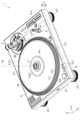
- Fig. 1 is a perspective view showing an audio device 1 according to this embodiment
- Fig. 2 is a plan view showing the audio device 1.
- Fig. 3 is a perspective view showing a slip sheet SS, a slip mat SM, and a control panel DS placed on a turntable 41 of the audio device 1.
- the audio device 1 according to this embodiment includes a housing 2, a tone arm 3, a rotor 4, a rotating shaft 5, and a load adjustment member 6, and outputs a signal in response to a user's operation on a control panel DS.
- the audio device 1 transmits operation information including rotation information indicating the rotation state of the control panel DS.
- the rotation information includes the rotation angle, rotation direction, rotation speed, etc. of the control panel DS.
- the audio device 1 also transmits information acquired by the tone arm 3 from the control panel DS.
- the turntable 41 of the rotating body 4 supports an interposition member MT including a slip sheet SS, a slip mat SM, and a control panel DS, as shown in Fig. 3, and rotates about a rotation axis Rx.
- the interposition member MT is an object to be clamped between a table 53 (see Fig. 5) and a load adjustment member 6, which will be described later.
- the operation panel DS is an analog record on which audio information is recorded, a time code record on which a time code is recorded, or a disk imitating an analog record.
- the operation panel DS is placed on the placement surface 411 of the turntable 41 via a slip sheet SS and a slip mat SM.
- the operation panel DS is sandwiched between the table 53 of the rotating shaft portion 5 and the load adjustment member 6.
- the operation panel DS is rotated together with the turntable 41 concentrically with the turntable 41.
- the operation panel DS is rotatable relative to the turntable 41 in the rotation direction of the turntable 41, and is also rotatable relative to the rotation direction of the turntable 41 in the opposite direction. This allows the user to perform rotation operations such as a scratch operation on the operation panel DS.
- the operation panel DS has a substantially circular hole DS1 at the center thereof penetrating the operation panel DS.
- the hole DS1 is a hole through which a meshing portion 543 (see FIG. 7 ) disposed on the outer side of the shaft member 51 of the rotating shaft portion 5 is inserted.
- the slip sheet SS and slip mat SM are friction reducing members.
- Each of the slip sheet SS and slip mat SM is a disk of approximately the same size as the operation panel DS.
- the material of each of the slip sheet SS and slip mat SM can be changed as desired according to the user's preferences, and it is also possible to use commercially available slip sheets and slip mats as they are.
- the slip sheet SS has a circular hole SS1 in the center, through which the meshing portion 543 of the rotating shaft portion 5 is inserted.
- the slip mat SM has a circular hole SM1 in the center, through which the meshing portion 543 is inserted.
- the slip sheet SS and the slip mat SM reduce the frictional force generated between the operation panel DS and the mounting surface 411, thereby reducing the frictional force when the operation panel DS rotates relative to the mounting surface 411.
- the slip sheet SS, which rotates integrally with the turntable 41, and the slip mat SM, which rotates integrally with the operation panel DS are provided to facilitate the relative rotation of the operation panel DS with respect to the mounting surface 411.
- the slip sheet SS and the slip mat SM may be omitted.
- the intermediate member MT is formed by the operation panel DS.
- the intermediate member MT is pushed up from below by the table 53 and separated from the mounting surface 411, and is also pressed toward the turntable 41 by the load adjustment member 6. This adjusts the rotation load of the operation panel DS.
- the three mutually orthogonal directions are the +X direction, the +Y direction, and the +Z direction.
- the +Y direction is the direction away from the base part 21 along the normal of the base part 21 that constitutes the top surface of the housing 2.
- the +Y direction is the opposite to the vertical direction when the audio device 1 is installed on the installation surface.
- the +Z direction is the downward direction.
- the direction opposite to the +X direction is the -X direction
- the direction opposite to the +Y direction is the -Y direction
- the direction opposite to the +Z direction is the -Z direction.
- the axis along the +X direction is the X axis
- the axis along the +Y direction is the Y axis
- the axis along the +Z direction is the Z axis.
- the housing 2 is a housing formed in a substantially rectangular parallelepiped shape.
- the housing 2 includes a first housing 2A and a second housing 2B located in the -Y direction relative to the first housing 2A, and is configured by combining the first housing 2A and the second housing 2B.
- the housing 2 includes a base portion 21, a bottom surface 22, and side surfaces 23.
- the bottom surface 22 is a surface of the housing 2 facing the -Y direction and facing the installation surface on which the audio device 1 is installed.
- the bottom surface 22 is provided with a plurality of legs 221 that come into contact with the installation surface.
- the side surfaces 23 are the ⁇ X direction side surfaces and the ⁇ Z direction side surfaces of the housing 2 .
- the base unit 21 is the surface of the first housing 2A facing the +Y direction, and constitutes the top surface of the housing 2.
- various buttons and the tone arm 3 are arranged, and the turntable 41 of the rotating body 4 is exposed.
- various buttons are arranged, such as a power switch 211, a start/stop button 212, a speed change button 213, and a tempo slider 214.
- a power switch 211, a start/stop button 212, and a speed change button 213 are provided adjacent to the turntable 41.
- a user can rotate and stop the turntable 41 by operating the power switch 211 and the start/stop button 212.
- a user can set the rotation speed of the turntable 41 to one of 33 RPM, which is suitable for playing LPs, and 45 RPM, which is suitable for playing EPs, by operating the speed change button 213.
- the tempo slider 214 is provided to be slidable along the Z axis on the +X direction portion of the base portion 21. The user can adjust the rotation speed of the rotating body 4 by operating the tempo slider 214, and thereby adjust the rotation speed of the operation panel DS.
- the base portion 21 has a circular recess 215 that opens in the +Y direction.
- the turntable 41 of the rotating body 4 is disposed in the recess 215.
- the tone arm 3 acquires audio information from an analog record with an appropriate needle pressure, and acquires a time code from a time code record.
- the tone arm 3 is provided at a corner of the base portion 21 in the +X direction and in the -Z direction, and is provided rotatable about a rotation axis along the Y axis.
- the tone arm 3 includes a head shell 31 to which a cartridge having a record needle attached thereto for playing a record is attached.
- the rotating body 4 is rotated about a rotation axis Rx along the Y axis by a drive unit 91 described later.
- the rotating body 4 includes a turntable 41 that configures a portion of the rotating body 4 in the +Y direction, and also includes a support member 42 (see FIG. 5 ) described later.
- the support member 42 will be described in detail later.
- the turntable 41 is provided on the base portion 21.
- the turntable 41 is formed in a generally truncated cone shape with an outer diameter that decreases in the +Y direction.
- the turntable 41 has a placement surface 411 on which the slip sheet SS, the slip mat SM, and the operation panel DS can be placed.
- the placement surface 411 is the top surface of the turntable 41 facing the +Y direction, and is a surface perpendicular to the rotation axis Rx.
- the turntable 41 has a substantially circular opening 412 in the center when viewed from the +Y direction.
- the rotating shaft unit 5 is disposed inside the opening 412.
- a shaft member 51 constituting the rotating shaft unit 5 is inserted through the opening 412 along the Y axis. That is, the shaft member 51 is inserted through the turntable 41 along the Y axis.
- a table 53 constituting the rotating shaft unit 5 moves in the ⁇ Y directions relative to the turntable 41 via the opening 412.
- the turntable 41 is rotated around a shaft member 51 .
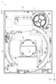
- FIG. 4 is a view of the audio device 1 from the -Y direction with the second housing 2B removed.
- Fig. 5 is a view showing a cross section of the audio device 1 taken along line VV in Fig. 2. Note that in Fig. 5, the second housing 2B is not shown, and some of the configuration inside the housing 2 is also not shown.
- the acoustic device 1 includes a drive unit 91 and a rotation support unit 92 inside the housing 2, and also includes a rotation detection unit 93 as shown in FIG.
- the driving unit 91 rotates the rotating body 4 at a rotation speed set by the speed change button 213 or the tempo slider 214 .
- the rotation support part 92 is a bottomed cylindrical member fixed inside the housing 2, and rotatably supports therein the support member 42 of the rotating body 4 and the shaft member 51 of the rotating shaft part 5.
- a rotation detection part 93 is provided inside the rotation support part 92. 5, the rotation detection unit 93 includes a first detection unit 931 that detects the rotation state of the turntable 41, and a second detection unit 932 that detects the rotation state of the rotating shaft unit 5 and, in turn, the rotation state of the operation panel DS.
- the rotation state of the turntable 41 detected by the first detection unit 931 is used for rotation control of the turntable 41.
- the rotation state of the rotating shaft unit 5 detected by the second detection unit 932 may be transmitted to the outside as the rotation state of the operation panel DS.
- the rotating body 4 includes the turntable 41 and, as shown in FIG.
- the support member 42 in a state in which the support member 42 supports the turntable 41, is supported rotatably about the rotation axis Rx by the rotation support portion 92.
- the support member 42 has a first cylindrical portion 43, a second cylindrical portion 44, and an expanded diameter portion 45.
- the first cylindrical portion 43 is formed in a substantial Y-shape when viewed from the +Z direction.
- the first cylindrical portion 43 has a connecting portion 431, a through portion 432, a first recess 433, and a second recess 434.
- the connecting portion 431 is a portion that constitutes the end portion in the +Y direction of the first cylindrical portion 43.
- the connecting portion 431 is an outer peripheral portion of the first cylindrical portion 43, and is formed in an annular shape when viewed from the +Y direction.
- the connecting portion 431 is connected to the surface of the turntable 41 opposite to the mounting surface 411, and is connected to the turntable 41 by a screw SC1 (see FIG. 3).
- the through portion 432 passes through the first cylindrical portion 43 along the Y axis.
- the shaft member 51 is inserted into the through portion 432 along the Y axis.
- the first recess 433 is provided in the center of the first cylindrical portion 43 when viewed from the +Y direction, and is disposed inside the connecting portion 431.
- the first recess 433 opens in the +Y direction, and a +Y direction portion of the table 53 of the rotating shaft portion 5 is disposed within the first recess 433.
- the second recess 434 is formed in a portion in the ⁇ Y direction with respect to the first recess 433, so as to be continuous with the bottom of the first recess 433. Within the second recess 434, a portion of the table 53 in the ⁇ Y direction is disposed.
- FIG. 6 is a perspective view of the rotating shaft 5 and the load adjustment member 6 as viewed from the +Y direction.
- Fig. 7 is a diagram showing a cross section of the rotating shaft 5 and the load adjustment member 6 along the XY plane.
- the rotating shaft unit 5 rotates about the rotation axis Rx integrally with the support member 42 and thus the rotor 4, and can also rotate about the rotation axis Rx integrally with the operation panel DS held together with the load adjustment member 6.
- the rotating shaft unit 5 includes a shaft member 51, a connecting member 52, and a table 53.
- the recess 511 is a portion of the shaft member 51 recessed in the circumferential direction centered on the rotation axis Rx, and is provided at the end of the shaft member 51 in the +Y direction.
- a claw member 625 (see FIG. 11 ) of the load adjustment member 6 that slides along the XZ plane is inserted into the recess 511.
- a surface 5111 of the recess 511 facing the -Y direction is inclined so that its diameter increases toward the +Y direction. Therefore, when the user moves the load adjustment member 6 from the shaft member 51 in the +Y direction, the claw member 625 comes out of the recess 511, and the load adjustment member 6 can be removed from the shaft member 51.
- the fixing hole 512 is a hole into which the connecting member 52 that connects the shaft member 51 and the table 53 is inserted and fixed. The shaft member 51 and the table 53 are connected by the connecting member 52.
- the step portion 513 is provided on the outer circumferential surface of the shaft member 51 centered on the rotation axis Rx.
- the step portion 513 has a first step portion 5131 and a second step portion 5132.
- the first step portion 5131 is a portion whose diameter is reduced in the circumferential direction centered on the rotation axis Rx.
- the second step portion 5132 is disposed further in the +Y direction than the first step portion 5131.
- the second step portion 5132 is a portion whose diameter is smaller than that of the first step portion 5131 along the circumferential direction centered on the rotation axis Rx.
- the movement restricting portion 514 is provided at a position in the -Y direction with respect to the step portion 513.
- the expanded diameter portion 515 is provided at the end of the shaft member 51 in the -Y direction, and is a portion that is expanded into a circular shape when viewed from the +Y direction.
- the end of the expanded diameter portion 515 is inserted into the second detection portion 932, whereby the second detection portion 932 detects the rotation state of the rotating shaft portion 5 and the load adjustment member 6, and thus the rotation state of the operation panel DS.
- FIG. 8 is a perspective view showing the shaft member 51 and the table 53.
- Fig. 8 is a perspective view showing the table 53 with the interlocking member 54 separated from the holding member 55.
- the table 53 is a movable member attached to the shaft member 51 so as to be movable in the ⁇ Y direction along the shaft member 51, and when the load adjustment member 6 is attached to the shaft member 51, it clamps the interposed member MT interposed between the table 53 and the load adjustment member 6.
- the table 53 includes an engaging member 54, a holding member 55, and a magnet 56.
- the interlocking member 54 is attached around the shaft member 51 and interlocks with the load adjusting member 6 attached to the shaft member 51.
- the interlocking member 54 has a through portion 541, a covering portion 542, an interlocking portion 543, a cylindrical portion 544, and a guide hole 545.
- the through portion 541 passes through the meshing member 54 along the Y axis.
- the shaft member 51 is inserted into the through portion 541.
- the through portion 541 is provided in the center of the covering portion 542 when viewed from the +Y direction.
- the covering portion 542 is formed in a circular shape when viewed from the +Y direction, and covers the arrangement portion 553 of the holding member 55 in the +Y direction.
- the meshing portion 543 is a cylindrical portion that protrudes in the +Y direction from the center of the covering portion 542 when viewed from the +Y direction.
- the meshing portion 543 is a cylindrical portion that protrudes in the +Y direction from the periphery of the through portion 541.
- the meshing portion 543 has a plurality of protrusions 5431 that protrude in the +Y direction from the end portion in the +Y direction and are arranged at equal intervals along the circumferential direction of the meshing portion 543.
- the plurality of protrusions 5431 mesh with a meshing portion 655 (see FIG. 13) of the load adjustment member 6, which will be described later, and this allows the table 53, and therefore the rotating shaft portion 5 and the load adjustment member 6, to rotate integrally around the rotating axis Rx.
- the tubular portion 544 is a cylindrical portion that protrudes in the -Y direction from the center of the covering portion 542 when viewed from the -Y direction, and the through portion 541 penetrates the inside along the Y axis.
- the tubular portion 544 surrounds the periphery of the shaft member 51.
- the tubular portion 544 has, on its inner circumferential surface, a first tubular portion 5441 corresponding to the first step portion 5131 and a second tubular portion 5442 corresponding to the second step portion 5132.
- the guide hole 545 is an elongated hole having a major axis along the Y axis. The connecting member 52 to be inserted into the fixing hole 512 passes through the guide hole 545.
- the insertion opening 551 penetrates the holding member 55 along the Y axis.
- the cylindrical portion 544 of the engagement member 54 is inserted into the insertion opening 551.
- the contact surface 552 is a surface of the holding member 55 in the +Y direction.
- the contact surface 552 comes into contact with the intermediate member MT, and together with the load adjustment member 6, holds the intermediate member MT in the Y axis direction.
- the placement portion 553 is a recess provided around the insertion opening 551, and is formed in a ring shape when viewed from the +Y direction.
- the bottom of the placement portion 553 is provided with a plurality of holes 554 through which the screws SC2 are inserted from the -Y direction, and also with a ring-shaped recess 555.
- a ring-shaped magnet 56 is placed in the recess 555 from the +Y direction.
- the placement portion 553 is covered by the covering portion 542. That is, the magnet 56 is not exposed to the outside of the table 53.
- the guide hole 556 is an elongated hole having a major diameter along the Y-axis.
- a connecting member 52 which is a pin that is inserted through the guide hole 545 and then into the fixed hole 512, is inserted into the guide hole 556.
- the guide hole 556 overlaps with the guide hole 545 when viewed along the insertion direction of the connecting member 52 into the fixed hole 512. Therefore, the table 53 having the holding member 55 is rotatable together with the shaft member 51 about the rotation axis Rx along the Y-axis, and is also movable along the shaft member 51 in the ⁇ Y direction relative to the shaft member 51.
- the table 53 has a biasing member 57 (see Figure 14) that suppresses rattle between the connecting member 52 fixed to the shaft member 51 and the engaging member 54 and the retaining member 55.
- the table 53 When the load adjustment member 6 is not attached to the shaft member 51, the table 53 is disposed in a position (first position) where it contacts the movement restricting portion 514. When the table 53 is disposed in the first position, the contact surface 552 is disposed in the -Y direction from the mounting surface 411 of the turntable 41. On the other hand, when the load adjustment member 6 is disposed on the shaft member 51 , depending on the position of the load adjustment member 6 , it can be disposed in the +Y direction from the mounting surface 411 of the turntable 41 .
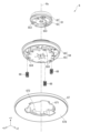
- FIGS. 9 and 10 are exploded perspective views showing the load adjustment member 6. More specifically, Fig. 9 is an exploded perspective view showing the load adjustment member 6 as viewed from the +Y direction, and Fig. 10 is an exploded perspective view showing the load adjustment member 6 as viewed from the -Y direction.
- the load adjustment member 6 is attached to the shaft member 51, attracts the table 53, and holds the interposed member MT on the Y axis together with the table 53. Then, a part of the load adjustment member 6 approaches the turntable 41 and presses the interposed member MT interposed between the load adjustment member 6 and the table 53 toward the turntable 41, thereby adjusting the rotational load of the interposed member MT with respect to the turntable 41.
- the load adjustment member 6 includes an adjustment member 61, an intermediate member 64, a pressing member 67, and a biasing member 68 as shown in FIGS. 7, 9, and 10, and further includes a magnet 69 as shown in FIGS.
- FIG. 11 is an exploded perspective view showing the adjustment member 61 as viewed from the +Y direction.
- the adjustment member 61 moves the intermediate member 64 along the Y axis to adjust the position of the pressing member 67, and thereby adjusts the pressing force against the spacer member MT.
- the adjustment member 61 includes a locking member 62 and a cover member 63, as shown in FIG.
- the locking member 62 is fixed to the cover member 63 by a plurality of screws SC3.
- the locking member 62 locks the entire adjustment member 61 to the shaft member 51.
- the locking member 62 has a seat member 621, a restricting member 624, a claw member 625, and biasing members 626 and 627.
- the base member 621 is a circular plate when viewed from the +Y direction.
- the base member 621 has a through hole 622 and a plurality of holes 623.
- the through hole 622 is provided in the center of the base member 621 when viewed from the +Y direction, and passes through the base member 621 along the Y axis.
- the shaft member 51 is inserted into the through hole 622 along the Y axis.
- the claw member 625 which is biased by the biasing member 627 in a direction approaching the through hole 622, is inserted into the recess 511 (see FIGS. 6 and 7 ) of the shaft member 51 that has passed through the through hole 622.
- the adjustment member 61, and therefore the load adjustment member 6, are attached to the shaft member 51.
- Such a claw member 625 has an inclined surface 6251 corresponding to the surface 5111 of the recess 511 at the end inserted into the recess 511. Therefore, when the adjustment member 61 is moved in the +Y direction away from the shaft member 51, the claw member 625 moves along the surface 5111 in a direction away from the through-hole 622 against the biasing force of the biasing member 627. This allows the adjustment member 61, and therefore the load adjustment member 6, to be removed from the shaft member 51.
- the cover member 63 is combined with the locking member 62 so as to cover the locking member 62 in the +Y direction.
- the cover member 63 is formed in a substantially circular shape when viewed from the +Y direction, and has a bottomed cylindrical shape that opens in the -Y direction.
- the cover member 63 has a protrusion 631, handles 632, 633, a notch 634, and an outer circumferential protrusion 635.
- the protrusion 631 is provided on a top surface 63A of the cover member 63 facing the +Y direction, and protrudes in a substantially hemispherical shape in the +Y direction from the top surface 63A. As shown in Fig. 7, an inner surface 631A of the protrusion 631 is formed into a shape corresponding to the end of the shaft member 51 in the +Y direction. When the load adjustment member 6 is attached to the shaft member 51, the end of the shaft member 51 in the +Y direction, which is inserted through the through hole 622 of the locking member 62 in the +Y direction, comes into contact with the inner surface 631A.
- the claw members 625 are disposed at positions that allow them to be inserted into the recesses 511 when the ends of the shaft members 51 come into contact with the inner surfaces 631A.
- the handle portions 632, 633 are provided protruding from the top surface 63A at positions sandwiching the protruding portion 631.
- the handle portions 632, 633 are portions that are gripped by the user when rotating the adjustment member 61 relative to the intermediate member 64.
- the restricting member 624 is inserted through the cutout 634 in the +X direction.
- FIG. 12 is an exploded perspective view showing the intermediate member 64 as viewed from the +Y direction.
- Fig. 13 is a cross-sectional view showing the intermediate member 64 and the magnet 69 housed in the intermediate member 64.
- Fig. 13 is a view showing a cross section of the intermediate member 64 and the magnet 69 along the XY plane.
- the intermediate member 64 moves in the ⁇ Y direction in accordance with the rotation of the adjustment member 61 about the rotation axis Rx, and moves the pressing member 67 in the ⁇ Y direction to press the interposition member MT toward the turntable 41.
- the intermediate member 64 includes a holding member 65 and an engagement member 66 that covers the holding member 65 in the +Y direction.
- the holding member 65 is formed in a substantially circular shape when viewed from the +Y direction, and is combined with the meshing member 66 in a state in which the holding member 65 holds the magnet 69.
- the holding member 65 has a cylindrical portion 651, a through portion 652, an arrangement portion 653, and a plurality of insertion holes 654.
- the cylindrical portion 651 is provided in the center of the holding member 65 when viewed from the +Y direction, and protrudes cylindrically in the +Y direction from the +Y direction surface of the holding member 65 .
- the through portion 652 is provided in the cylindrical portion 651, and passes through the holding member 65 along the Y axis.
- the shaft member 51 is inserted into the through portion 652 along the Y axis.
- the placement portion 653 is provided in a ring shape on the outer side of the cylindrical portion 651 when viewed from the +Y direction.
- a ring-shaped magnet 69 is placed on the placement portion 653 from the +Y direction.
- the plurality of insertion holes 654 are provided on the periphery of the holding member 65 centered on the rotation axis Rx.
- a screw SC4 is inserted in the +Y direction into each insertion hole 654.
- Each screw SC4 is fixed to the meshing member 66, whereby the holding member 65 and the meshing member 66 are integrated together.
- the holding member 65 further includes a meshing portion 655 .
- the meshing portion 655 meshes with the meshing member 54 of the table 53.
- the meshing portion 655 is provided inside the cylindrical portion 651 and has a plurality of recesses 6551 that mesh with a plurality of protrusions 5431 (see FIG. 8 ) of the meshing member 54.
- the plurality of protrusions 5431 mesh with the plurality of recesses 6551, thereby integrating the load adjustment member 6 and the table 53, and allowing the load adjustment member 6 and the table 53 to rotate integrally around the shaft member 51.
- the holding member 65 cannot rotate relative to the shaft member 51, but can move relative to the shaft member 51 along the shaft member 51.
- the holding member 65 can rotate integrally with the shaft member 51, and can also move relatively in the ⁇ Y direction along the shaft member 51.
- the covering portion 662 covers the holding member 65 in the +Y direction when the holding member 65 and the meshing member 66 are combined. Therefore, a portion of the magnet 69 arranged in the arrangement portion 653 is covered by the covering portion 662.
- the cylindrical portion 663 is a cylindrical portion that protrudes in the +Y direction from the periphery of the opening 661.
- the adjustment member 61 is attached to the cylindrical portion 663.
- the spiral groove 664 is a spiral groove provided on the inner circumferential surface of the cylindrical portion 663.
- the spiral groove 664 is formed so as to be positioned in the +Y direction as it progresses clockwise when viewed from the +Y direction.
- the outer circumferential protrusion 635 of the adjustment member 61 described above is inserted into the spiral groove 664.
- the intermediate member 64 can rotate integrally with the shaft member 51 by the holding member 65, and can also move relatively in the ⁇ Y direction along the shaft member 51. Therefore, when the adjustment member 61 attached to the shaft member 51 is rotated in one direction about the rotation axis Rx, the intermediate member 64 moves in the -Y direction along the shaft member 51. When the adjustment member 61 is rotated in the other direction about the rotation axis Rx, the intermediate member 64 moves in the +Y direction along the shaft member 51.
- the pressing member 67 is combined with the intermediate member 64 in a loosely fitted state via a biasing member 68.
- the pressing member 67 holds the interposed member MT together with the table 53 attracted in the +Y direction by the magnet 69.
- the adjustment member 61 is rotated and the intermediate member 64 is moved in the -Y direction, the pressing member 67 presses the interposed member MT toward the mounting surface 411 of the turntable 41.
- the pressing member 67 is formed in a ring shape centered on the rotation axis Rx when viewed from the +Y direction.
- a pressing surface 67A facing the -Y direction of the pressing member 67 comes into contact with a surface facing the +Y direction of the intermediate member MT.
- the pressing surface 67A comes into contact with a surface facing the +Y direction of the operation panel DS.
- the pressing surface 67A may be provided with an elastic body made of silicone resin or the like in order to increase the degree of contact with the operation panel DS.
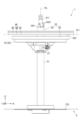
- Fig. 14 is a side view showing the rotating shaft portion 5 and the intermediate member MT as viewed from the +Z direction. In other words, it is a diagram showing the position of the contact surface 552 of the table 53 with respect to the mounting surface 411 in a state in which the load adjustment member 6 is not attached to the shaft member 51. In Fig. 14, the position of the mounting surface 411 is indicated by a dotted line.
- the table 53 is disposed at the end in the -Y direction of the movable range along the Y axis by its own weight, as shown in Fig. 14. In other words, when the load adjustment member 6 is not attached to the shaft member 51, the table 53 is disposed at the first position where it comes into contact with the movement restriction portion 514.
- a contact surface 552 of the table 53 that can come into contact with the interposed member MT is disposed in the ⁇ Y direction from the mounting surface 411 of the turntable 41. Therefore, the interposed member MT is supported by the mounting surface 411 of the turntable 41, and the contact surface 552 does not come into contact with the interposed member MT.
- the operation panel DS is placed on the placement surface 411, similar to a typical record player. Therefore, the user can quickly replace the operation panel DS.
- the magnet 69 of the load adjustment member 6 and the magnet 56 of the table 53 attract each other, but the load adjustment member 6 does not move, so the table 53 moves in the +Y direction.
- the pressing surface 67A of the pressing member 67 of the load adjustment member 6 and the contact surface 552 of the holding member 55 of the table 53 clamp the intermediate member MT on the Y axis.
- the table 53 is disposed at the +Y-direction end of their movable range along the Y-axis.
- the contact surface 552 of the table 53 is disposed in the +Y direction further than the mounting surface 411, as shown in Fig. 15. In this state, the intervening member MT is unlikely to come into contact with the mounting surface 411 of the turntable 41, and therefore the rotational load of the operation panel DS on the turntable 41 is minimized.
- the table 53 moves in the -Y direction while sandwiching the interposition member MT together with the pressing member 67. Then, when the intermediate member 64, the pressing member 67 and the table 53 move further in the -Y direction, the contact surface 552 is disposed on the same plane as the mounting surface 411, as shown in Fig. 16. In this case, the interposition member MT is not only supported from the -Y direction by the contact surface 552, but also supported from the -Y direction by the mounting surface 411.
- the pressing surface 67A of the pressing member 67 presses the interposed member MT toward the mounting surface 411.
- the interposed member MT is pressed in the -Y direction by the pressing surface 67A.
- the slip sheet SS and the slip mat SM are crushed in the ⁇ Y direction, and the operation panel DS is pressed strongly against the placement surface 411. This increases the frictional force when the operation panel DS rotates, and increases the rotational load of the operation panel DS against the turntable 41.
- the pressing force of the intermediate member MT against the turntable 41 can be adjusted according to the amount of rotation of the adjustment member 61 about the rotation axis Rx, and therefore the rotation load of the operation panel DS against the turntable 41 can be adjusted. Furthermore, since the load adjustment member 6 can be easily removed from the shaft member 51, replacement of the operation panel DS can be easily and quickly carried out.
- the rotation of the control panel DS is transmitted to the shaft member 51 via the load adjustment member 6 in contact with the control panel DS and the table 53 meshing with the load adjustment member 6, and the rotational state of the shaft member 51 is detected by the second detection unit 932. Therefore, the audio device 1 can detect the rotational state of the control panel DS around the rotation axis Rx by the second detection unit 932, and can transmit the detected rotational state of the control panel DS. In addition, when the tone arm 3 is being used, that is, when the information recorded on the control panel DS can be acquired by the tone arm 3, the audio device 1 transmits the acquired information and does not need to transmit the rotation state of the control panel DS.
- the acoustic device 1 includes a base portion 21 , a shaft member 51 , a turntable 41 , a table 53 , and a load adjustment member 6 .
- the shaft member 51 is inserted through the base portion 21.
- the turntable 41 is provided on the base portion 21 and rotates about the shaft member 51.
- the table 53 is provided so as to be movable along the shaft member 51.
- the table 53 corresponds to a moving member.
- the load adjustment member 6 is attached to the shaft member 51.
- the load adjustment member 6 approaches the turntable 41 along the shaft member 51 and presses the intervening member MT interposed between the load adjustment member 6 and the table 53 toward the turntable 41, thereby adjusting the rotation load of the operation panel DS of the intervening member MT relative to the turntable 41.
- the load adjustment member 6 attracts the table 53 by magnetic force, and holds the intervening member MT together with the table 53.
- the table 53 is attracted to the load adjustment member 6 by magnetic force, and the interposition member MT is sandwiched between the load adjustment member 6 and the table 53.
- the interposition member MT can be pressed in a direction toward the turntable 41. Therefore, the rotational load of the operation panel DS constituting the interposition member MT on the turntable 41 can be easily adjusted.
- the clamping of the intermediate member MT by the load adjustment member 6 and the table 53 can be released, so that the intermediate member MT can be placed on the turntable 41.
- the audio device 1 includes a tone arm 3 that can come into contact with a control panel DS of the intermediate member MT.
- the interposing member MT includes the operation panel DS which is a record such as an analog record on which audio information is recorded and a time code record on which a time code is recorded
- the information recorded on the operation panel DS can be obtained by the tone arm 3. Therefore, the versatility of the audio device 1 can be improved.
- the load adjustment member 6 has a magnet 69 that applies a magnetic force to the table 53.
- the magnet 69 corresponds to a magnetic force portion.
- the table 53 serving as a moving member has a magnet 56.
- the magnet 56 corresponds to a magnetic body on which the magnetic force of a magnet 69 acts. According to this configuration, when the load adjustment member 6 is attached to the shaft member 51, the table 53 can be attracted to the load adjustment member 6. Therefore, the load adjustment member 6 and the table 53 can sandwich the intermediate member MT.
- the load adjustment member 6 has an adjustment member 61 and a pressing member 67 .
- the adjustment member 61 is rotatable about the shaft member 51 .
- the pressing member 67 moves in the ⁇ Y direction along the shaft member 51 in conjunction with the rotation of the adjustment member 61 , and presses the intermediate member MT towards the turntable 41 .
- this configuration by adjusting the rotation amount of the adjustment member 61, it is possible to adjust the pressing force acting on the intermediate member MT, and in turn, it is possible to adjust the rotation load of the operation panel DS of the intermediate member MT relative to the turntable 41. Therefore, it is possible to easily adjust the rotation load of the operation panel DS.
- the turntable 41 has a mounting surface 411 on which the interposition member MT can be placed.
- the table 53 has a contact surface 552 that comes into contact with the interposition member MT when attracted to the load adjustment member 6.
- the contact surface 552 can be located closer to the load adjustment member 6 than the mounting surface 411. In other words, the contact surface 552 can be located in the +Y direction than the mounting surface 411.
- the interposition member MT can be disposed at a position closer to the load adjustment member 6 than the mounting surface 411. In other words, the interposition member MT can be raised above the mounting surface 411.
- the turntable 41 has an opening 412 through which the shaft member 51 is inserted.
- the table 53 is disposed inside the opening 412 when viewed from the load adjustment member 6 side of the table 53. In other words, the table 53 is disposed inside the opening 412 when viewed from the +Y direction. According to this configuration, when the contact surface 552 is disposed at a position closer to the load adjustment member 6 than the mounting surface 411, the table 53 can easily support the interposition member MT rotatably about the shaft member 51, independently of the turntable 41. Therefore, the table 53 alone can stably support the interposition member MT rotatably.
- the audio device 1 includes a turntable 41 , a shaft member 51 , a table 53 and a load adjustment member 6 .
- the turntable 41 has a mounting surface 411 on which a circular operation panel DS can be mounted.
- the turntable 41 rotates around a shaft member 51 together with the operation panel DS.
- the shaft member 51 passes through the turntable 41 .
- the table 53 has a contact surface 552 that can come into contact with the operation panel DS.
- the table 53 is provided so as to be movable along the shaft member 51.
- the table 53 corresponds to a moving member.
- the load adjustment member 6 is attached to the shaft member 51, attracts the table 53 by magnetic force, and holds the operation panel DS together with the table 53.
- the load adjustment member 6 approaches the turntable 41 along the shaft member 51 and presses the operation panel DS interposed between the load adjustment member 6 and the table 53 toward the turntable 41, thereby adjusting the rotation load of the operation panel DS relative to the turntable 41.
- the table 53 is movable between a first position where the contact surface 552 is located on the opposite side of the load adjustment member 6 from the mounting surface 411, and a second position where the contact surface 552 is located closer to the load adjustment member 6 than the mounting surface 411. That is, the table 53 is movable between the first position where the contact surface 552 is located in the +Y direction from the mounting surface 411, and the second position where the contact surface 552 is located in the -Y direction from the mounting surface 411.
- the audio device 1 can easily adjust the rotation load of the operation panel DS relative to the turntable 41. Furthermore, by attaching or detaching the load adjustment member 6 to or from the shaft member 51, it is possible to switch between a state in which the rotation load of the operation panel DS relative to the turntable 41 can be adjusted and a state in which the operation panel DS can be stably rotated by the turntable 41. Furthermore, by disposing the table 53 at the first position, the load adjustment member 6 can adjust the rotation load of the operation panel DS relative to the turntable 41. By disposing the table 53 at the second position, the operation panel DS held between the table 53 and the load adjustment member 6 can be supported independently from the turntable 41. Therefore, by allowing the table 53 to move between the first position and the second position, the adjustment range of the rotation load of the operation panel DS can be expanded.
- the audio device 1 includes the tone arm 3.
- the present invention is not limited to this, and the audio device 1 does not necessarily need to include the tone arm 3.
- the table 53 includes a magnet 56
- the load adjustment member 6 includes a magnet 69
- the magnets 56 and 69 are attracted to each other.
- one of the magnets 56, 69 may be replaced with a magnetic body such as a metal body.
- one of the table 53 and the load adjustment member 6 may include a magnet, and the other may include a magnetic body that is attracted by the magnet.
- the load adjustment member 6 includes an adjustment member 61 that is attached to the shaft member 51 and rotated by the user around the rotation axis Rx, an intermediate member 64 that meshes with the adjustment member 61 and moves in the ⁇ Y direction along the shaft member 51, a pressing member 67 that is connected to the intermediate member 64 and presses the intermediate member MT toward the turntable 41, a biasing member 68 that is interposed between the intermediate member 64 and the pressing member 67, and a magnet 69.
- the intermediate member 64 may be configured integrally with the pressing member 67.
- the pressing member 67 may have the configuration of the intermediate member 64, and the pressing member 67 may directly mesh with the adjustment member 61. Even in this case, the pressing member 67 can be brought closer to the turntable 41 depending on the amount of rotation of the adjustment member 61.
- the table 53 as a moving member can be positioned so that the contact surface 552 that can come into contact with the interposed member MT is located closer to the load adjustment member 6 side than the mounting surface 411 of the turntable 41. In other words, the table 53 can be positioned at the second position.
- the +Y direction end of the movable range of the table 53 along the shaft member 51 may be a position of the table 53 where the contact surface 552 is on the same plane as the mounting surface 411. In other words, the table 53 does not necessarily have to be positioned at a position where the contact surface 552 is closer to the +Y direction than the mounting surface 411.
- the turntable 41 has an opening 412 through which the shaft member 51 is inserted along the Y-axis and through which the table 53 is exposed.
- the opening 412 through which the table 53 is exposed may be located in another part of the turntable 41.
- a base portion A shaft member that passes through the base portion; a turntable provided on the base portion and configured to rotate around the shaft member; A moving member that is movable along the shaft member; a load adjustment member that is attached to the shaft member, moves along the shaft member close to the turntable, and presses an intermediate member interposed between the movable member and the shaft member toward the turntable to adjust a rotation load of the intermediate member relative to the turntable,
- the acoustic device characterized in that the load adjustment member attracts the moving member by magnetic force and holds the interposition member together with the moving member.
- the moving member is attracted to the load adjustment member by magnetic force, and the intermediate member is sandwiched between the load adjustment member and the moving member.
- the intermediate member can be pressed in the direction toward the turntable. Therefore, the rotation load of the intermediate member relative to the turntable can be easily adjusted.
- the clamping of the interposed member by the load adjustment member and the moving member can be released, so that the interposed member can be placed on the turntable. This allows the interposed member to rotate stably together with the turntable.
- An acoustic device comprising a tone arm capable of coming into contact with the intermediate member.
- the interposing member includes a record such as an analog record on which audio information is recorded and a time code record on which a time code is recorded
- the information recorded on the record can be obtained by the tone arm, thereby increasing the versatility of the audio device.
- An acoustic device comprising: the moving member having a magnetic body on which the magnetic force acts. According to this configuration, when the load adjustment member is attached to the shaft member, it is possible to easily attract the moving member to the load adjustment member, and therefore it is possible to easily clamp the intermediate member between the load adjustment member and the moving member.
- the load adjusting member is an adjustment member rotatable around the shaft member; a pressing member that moves along the shaft member as the adjustment member rotates and presses the intermediate member toward the turntable. According to this configuration, by rotating the adjustment member, the pressing member moves along the shaft member and presses the intermediate member against the turntable. According to this, by adjusting the rotation amount of the adjustment member, the pressing force acting on the intermediate member can be adjusted, and thus the rotation load of the intermediate member against the turntable can be adjusted. Therefore, it is possible to easily adjust the rotation load of the intermediate member.
- the turntable has a mounting surface on which the interposition member can be placed, the movable member has a contact surface that comes into contact with the intermediate member when the movable member is attracted to the load adjustment member,
- An acoustic device characterized in that the contact surface can be positioned closer to the load adjustment member than the placement surface.
- the intermediate member can be disposed at a position closer to the load adjustment member than the mounting surface. In other words, the intermediate member can be raised above the mounting surface. This allows the intermediate member to be disposed so as not to come into contact with the turntable, thereby reducing the rotation load of the intermediate member. Therefore, the adjustment range of the rotation load of the intermediate member can be expanded.
- the turntable has an opening through which the shaft member is inserted,
- the acoustic device characterized in that the movable member is disposed inside the opening when viewed from the load adjustment member side relative to the movable member. According to this configuration, when the contact surface is disposed at a position closer to the load adjustment member than the mounting surface, the movable member can easily support the intermediate member rotatably about the shaft member, independently of the turntable. Therefore, the movable member alone can stably support the intermediate member rotatably.
- a turntable having a mounting surface on which a disk can be placed and rotating together with the disk;
- a moving member having a contact surface capable of coming into contact with the disk and movably provided along the shaft member;
- a load adjustment member that is attached to the shaft member, moves along the shaft member close to the turntable, and presses the disk interposed between the disk and the movable member toward the turntable, thereby adjusting a rotation load of the disk relative to the turntable;
- the turntable rotates around the shaft member, the load adjustment member attracts the moving member by magnetic force and holds the disk together with the moving member;
- the acoustic device is characterized in that the movable member is movable between a first position in which the contact surface is located on the opposite side of the load adjustment member from the mounting surface, and a second position in which the contact surface is located on the load adjustment member side from the mounting surface.
- the rotation load of the disk on the turntable can be easily adjusted, similarly to the above-mentioned audio device. Also, by attaching or detaching the load adjustment member to or from the shaft member, it is possible to switch between a state in which the rotation load of the disk on the turntable can be adjusted and a state in which the disk can be stably rotated by the turntable. Furthermore, by disposing the movable member at the first position, the load adjustment member can adjust the rotation load of the disk relative to the turntable. By disposing the movable member at the second position, the disk held between the load adjustment member and the movable member can be supported independently of the turntable. Therefore, by allowing the movable member to move between the first position and the second position, the adjustment range of the rotation load of the disk can be expanded.
Landscapes
- Fittings On The Vehicle Exterior For Carrying Loads, And Devices For Holding Or Mounting Articles (AREA)
- Holding Or Fastening Of Disk On Rotational Shaft (AREA)
Priority Applications (2)
| Application Number | Priority Date | Filing Date | Title |
|---|---|---|---|
| PCT/JP2023/000735 WO2024150399A1 (ja) | 2023-01-13 | 2023-01-13 | 音響装置 |
| JP2024569968A JP7821333B2 (ja) | 2023-01-13 | 2023-01-13 | 音響装置 |
Applications Claiming Priority (1)
| Application Number | Priority Date | Filing Date | Title |
|---|---|---|---|
| PCT/JP2023/000735 WO2024150399A1 (ja) | 2023-01-13 | 2023-01-13 | 音響装置 |
Publications (1)
| Publication Number | Publication Date |
|---|---|
| WO2024150399A1 true WO2024150399A1 (ja) | 2024-07-18 |
Family
ID=91896683
Family Applications (1)
| Application Number | Title | Priority Date | Filing Date |
|---|---|---|---|
| PCT/JP2023/000735 Ceased WO2024150399A1 (ja) | 2023-01-13 | 2023-01-13 | 音響装置 |
Country Status (2)
| Country | Link |
|---|---|
| JP (1) | JP7821333B2 (https=) |
| WO (1) | WO2024150399A1 (https=) |
Citations (4)
| Publication number | Priority date | Publication date | Assignee | Title |
|---|---|---|---|---|
| JPS6026663U (ja) * | 1983-07-27 | 1985-02-22 | ティーディーケイ株式会社 | デイスクスタビライザ |
| WO2006103904A1 (ja) * | 2005-03-29 | 2006-10-05 | Pioneer Corporation | 負荷調整装置、スイッチ装置、情報処理装置、dj用再生装置および再生装置 |
| US20080101183A1 (en) * | 2006-10-26 | 2008-05-01 | Stanton Magnetics, Inc. | Variable slippage control for a disk jockey control surface |
| WO2022168282A1 (ja) * | 2021-02-05 | 2022-08-11 | AlphaTheta株式会社 | 回転操作子及び操作装置 |
Family Cites Families (2)
| Publication number | Priority date | Publication date | Assignee | Title |
|---|---|---|---|---|
| WO2008120397A1 (ja) | 2007-04-02 | 2008-10-09 | Pioneer Corporation | 操作装置及び情報再生装置 |
| WO2020240612A1 (ja) | 2019-05-24 | 2020-12-03 | AlphaTheta株式会社 | 回転操作装置 |
-
2023
- 2023-01-13 JP JP2024569968A patent/JP7821333B2/ja active Active
- 2023-01-13 WO PCT/JP2023/000735 patent/WO2024150399A1/ja not_active Ceased
Patent Citations (4)
| Publication number | Priority date | Publication date | Assignee | Title |
|---|---|---|---|---|
| JPS6026663U (ja) * | 1983-07-27 | 1985-02-22 | ティーディーケイ株式会社 | デイスクスタビライザ |
| WO2006103904A1 (ja) * | 2005-03-29 | 2006-10-05 | Pioneer Corporation | 負荷調整装置、スイッチ装置、情報処理装置、dj用再生装置および再生装置 |
| US20080101183A1 (en) * | 2006-10-26 | 2008-05-01 | Stanton Magnetics, Inc. | Variable slippage control for a disk jockey control surface |
| WO2022168282A1 (ja) * | 2021-02-05 | 2022-08-11 | AlphaTheta株式会社 | 回転操作子及び操作装置 |
Also Published As
| Publication number | Publication date |
|---|---|
| JPWO2024150399A1 (https=) | 2024-07-18 |
| JP7821333B2 (ja) | 2026-02-26 |
Similar Documents
| Publication | Publication Date | Title |
|---|---|---|
| JP7261880B2 (ja) | 音響装置 | |
| JP7693837B2 (ja) | 回転操作子、操作装置及び音響制御装置 | |
| JP7821333B2 (ja) | 音響装置 | |
| JP7521015B2 (ja) | 回転操作子及び操作装置 | |
| CN101273323B (zh) | 操作输入装置及使用其的电子设备 | |
| JPH038030B2 (https=) | ||
| WO2026004066A1 (ja) | 音響装置 | |
| JP4442631B2 (ja) | 光ディスク装置 | |
| WO2020255288A1 (ja) | 音響装置 | |
| JP4196277B2 (ja) | 電子機器 | |
| JP3829721B2 (ja) | ディスククランプ装置、記録及び/又は再生装置ならびにディスク評価装置 | |
| JP2005106847A (ja) | 回転連結ユニット及び撮像装置 | |
| JP4141360B2 (ja) | 回転連結ユニット及び撮像装置 | |
| JP2009032319A (ja) | ディスク装置 | |
| JP2008251091A (ja) | ディスククランプ装置 | |
| JP2020170326A (ja) | 回転摘みの回転構造およびこれを用いた電子機器 | |
| WO2026004056A1 (ja) | 音響装置 | |
| JPH10162464A (ja) | 磁気ディスク装置 | |
| KR100386220B1 (ko) | 하우징 | |
| JPH0721646A (ja) | ディスク駆動装置 | |
| JP2000132957A (ja) | 記録及び/又は再生装置 | |
| JP2000182304A (ja) | ディスククランプ装置とその利用装置 | |
| JPH0750052A (ja) | ディスク記録再生装置のディスク支持機構 | |
| JPH05258453A (ja) | ディスク駆動装置 | |
| JPS63191903A (ja) | ホ−ル素子による位置検出器 |
Legal Events
| Date | Code | Title | Description |
|---|---|---|---|
| 121 | Ep: the epo has been informed by wipo that ep was designated in this application |
Ref document number: 23916020 Country of ref document: EP Kind code of ref document: A1 |
|
| ENP | Entry into the national phase |
Ref document number: 2024569968 Country of ref document: JP Kind code of ref document: A |
|
| WWE | Wipo information: entry into national phase |
Ref document number: 2024569968 Country of ref document: JP |
|
| NENP | Non-entry into the national phase |
Ref country code: DE |
|
| 122 | Ep: pct application non-entry in european phase |
Ref document number: 23916020 Country of ref document: EP Kind code of ref document: A1 |