WO2024143188A1 - レバー装置及びそれを備えた作業機 - Google Patents
レバー装置及びそれを備えた作業機 Download PDFInfo
- Publication number
- WO2024143188A1 WO2024143188A1 PCT/JP2023/046115 JP2023046115W WO2024143188A1 WO 2024143188 A1 WO2024143188 A1 WO 2024143188A1 JP 2023046115 W JP2023046115 W JP 2023046115W WO 2024143188 A1 WO2024143188 A1 WO 2024143188A1
- Authority
- WO
- WIPO (PCT)
- Prior art keywords
- lever
- support shaft
- movable body
- engagement portion
- spring hook
- Prior art date
- Legal status (The legal status is an assumption and is not a legal conclusion. Google has not performed a legal analysis and makes no representation as to the accuracy of the status listed.)
- Ceased
Links
Images





Classifications
-
- G—PHYSICS
- G05—CONTROLLING; REGULATING
- G05G—CONTROL DEVICES OR SYSTEMS INSOFAR AS CHARACTERISED BY MECHANICAL FEATURES ONLY
- G05G1/00—Controlling members, e.g. knobs or handles; Assemblies or arrangements thereof; Indicating position of controlling members
- G05G1/04—Controlling members for hand actuation by pivoting movement, e.g. levers
-
- E—FIXED CONSTRUCTIONS
- E02—HYDRAULIC ENGINEERING; FOUNDATIONS; SOIL SHIFTING
- E02F—DREDGING; SOIL-SHIFTING
- E02F9/00—Component parts of dredgers or soil-shifting machines, not restricted to one of the kinds covered by groups E02F3/00 - E02F7/00
- E02F9/16—Cabins, platforms, or the like, for drivers
- E02F9/166—Cabins, platforms, or the like, for drivers movable, tiltable or pivoting, e.g. movable seats, dampening arrangements of cabins
-
- E—FIXED CONSTRUCTIONS
- E02—HYDRAULIC ENGINEERING; FOUNDATIONS; SOIL SHIFTING
- E02F—DREDGING; SOIL-SHIFTING
- E02F9/00—Component parts of dredgers or soil-shifting machines, not restricted to one of the kinds covered by groups E02F3/00 - E02F7/00
- E02F9/20—Drives; Control devices
-
- E—FIXED CONSTRUCTIONS
- E02—HYDRAULIC ENGINEERING; FOUNDATIONS; SOIL SHIFTING
- E02F—DREDGING; SOIL-SHIFTING
- E02F9/00—Component parts of dredgers or soil-shifting machines, not restricted to one of the kinds covered by groups E02F3/00 - E02F7/00
- E02F9/20—Drives; Control devices
- E02F9/2004—Control mechanisms, e.g. control levers
-
- F—MECHANICAL ENGINEERING; LIGHTING; HEATING; WEAPONS; BLASTING
- F16—ENGINEERING ELEMENTS AND UNITS; GENERAL MEASURES FOR PRODUCING AND MAINTAINING EFFECTIVE FUNCTIONING OF MACHINES OR INSTALLATIONS; THERMAL INSULATION IN GENERAL
- F16H—GEARING
- F16H21/00—Gearings comprising primarily only links or levers, with or without slides
- F16H21/10—Gearings comprising primarily only links or levers, with or without slides all movement being in, or parallel to, a single plane
-
- G—PHYSICS
- G05—CONTROLLING; REGULATING
- G05G—CONTROL DEVICES OR SYSTEMS INSOFAR AS CHARACTERISED BY MECHANICAL FEATURES ONLY
- G05G5/00—Means for preventing, limiting or returning the movements of parts of a control mechanism, e.g. locking controlling member
-
- G—PHYSICS
- G05—CONTROLLING; REGULATING
- G05G—CONTROL DEVICES OR SYSTEMS INSOFAR AS CHARACTERISED BY MECHANICAL FEATURES ONLY
- G05G5/00—Means for preventing, limiting or returning the movements of parts of a control mechanism, e.g. locking controlling member
- G05G5/005—Means for preventing, limiting or returning the movements of parts of a control mechanism, e.g. locking controlling member for preventing unintentional use of a control mechanism
-
- G—PHYSICS
- G05—CONTROLLING; REGULATING
- G05G—CONTROL DEVICES OR SYSTEMS INSOFAR AS CHARACTERISED BY MECHANICAL FEATURES ONLY
- G05G5/00—Means for preventing, limiting or returning the movements of parts of a control mechanism, e.g. locking controlling member
- G05G5/05—Means for returning or tending to return controlling members to an inoperative or neutral position, e.g. by providing return springs or resilient end-stops
Definitions
- the present invention aims to provide a lever device that can apply the biasing force of a tension spring to a lever even when the rotation angle of the movable body is small, and a work machine equipped with the same.
- a lever device comprises a fixed body, a movable body rotatably supported on the fixed body via a first support shaft, a lever for rotating the movable body around the first support shaft, the lever being rotatably supported on a second support shaft provided on the movable body to a pressed-down position and a pulled-up position rotated upward from the pressed-down position, a tension spring for biasing the lever, and a switching mechanism for switching the direction of the biasing force of the tension spring between the pressed-down position and the pulled-up position so that the biasing force of the tension spring acts in a direction to pull down the lever at the pressed-down position and acts in a direction to pull up the lever at the pulled-up position, the switching mechanism being a rotating member that rotates integrally with the lever around the second support shaft,
- the link has a rotating member provided with a first spring hook and a first engagement part arranged at a position sandwiching the second support shaft when viewed from the axial direction of the third support shaft
- the side to which the first spring hook portion moves when the lever is pulled up and operated is defined as the first side
- the side opposite to the first side is defined as the second side
- the first spring hook portion moves to the first side
- the first engagement portion and the second engagement portion move to the second side
- the second spring hook portion moves to the first side
- the first spring hook portion moves to the second side
- the first engagement portion and the second engagement portion move to the first side
- the movable body may have a support tube that supports the second support shaft so that it can rotate freely around its axis, the lever may be attached to the second support shaft on one side of the support tube in the axial direction, and the guide plate may be fixed to the second support shaft on the other side of the support tube in the axial direction.
- the lever may be an operation lock lever that switches an actuator provided on the work machine between an operable state and an inoperable state.
- the second spring hook portion moves to the side to which the first spring hook portion moves due to the rotation of the link accompanying the movement of the first engagement portion by operating the lever, so that the central axis of the tension spring can be moved away from the center of the second support shaft to an appropriate position in the pressed-down position and the pulled-up position, and the biasing force of the tension spring on the lever can be applied even when the rotation angle of the movable body is small.
- FIG. FIG. FIG. 4 is a perspective view showing a state in which a control device is supported on a support frame.
- FIG. 1 is a side view of the controller in the lowered position without the console cover.
- FIG. 1 is a side view of the controller in the raised position without the console cover.
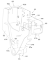
- FIG. 2 is a perspective view of the control device without the console cover.
- FIG. 2 is a perspective view of the control device without the console cover.
- FIG. 2 is a perspective view of the control device without the console cover.
- FIG. 2 is a perspective view of the control device without the console cover.
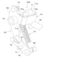
- FIG. FIG. FIG. FIG. 2 is an exploded perspective view of the switching mechanism and its surroundings.
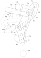
- FIG. 1 is a schematic side view of the movable body, the lever, and the switching mechanism in a lowered position.
- FIG. FIG. 15 is an enlarged view of the switching mechanism in FIG.
- FIG. 14 . 13 is a schematic side view of the movable body, the lever, and the switching mechanism during rotation.
- FIG. 17 is an enlarged view of the switching mechanism in FIG. 16 .
- 13 is a schematic side view of the movable body, the lever, and the switching mechanism during rotation.
- FIG. 19 is an enlarged view of the switching mechanism in FIG. 18 .
- 1 is a schematic side view of the movable body, the lever, and the switching mechanism in a raised position.
- FIG. FIG. 23 is an enlarged view of the switching mechanism in FIG. 22 .
- FIG. 1 is a schematic side view showing the overall configuration of a work machine 1 according to this embodiment.
- a backhoe which is a rotating work machine, is shown as an example of the work machine 1.
- the work machine 1 comprises a machine body (swivel base) 2, a traveling device 3, and a work device 4.
- the machine body 2 is equipped with a driver's seat 6 where the operator (driver) sits, and a four-poster rope 15.
- the rope 15 is a canopy type with a roof 19.
- the movable body 32 is provided with the left steering lever 23L, the remote control valve 24, the armrest 26L, the detection switch 51, the operation lock lever 30, the tension spring 47, the switching mechanism 33, and the guide plate 52.
- the movable body 32 is supported by a first support shaft 39 provided on the fixed body 31 so as to be rotatable about its axis.
- a through hole 82 is formed in the lower part of the first wall part 53 of the movable body 32, through which the left end side of the second spring hook part 80 is inserted.
- the lower edge of the through hole 82 is formed in a substantially arc shape centered on the third support shaft 77, and the upper edge is formed in a substantially straight line. Since the biasing force of the tension spring 47 acts on the second spring hook part 80 in a direction that pulls the second spring hook part 80 upward, the upper edge of the through hole 82 is formed in a straight line to provide a gap between the upper edge and the second spring hook part 80 so that the second spring hook part 80 is not pressed against the upper edge of the through hole 82.
- a preferred embodiment of the present invention provides a lever device 27 and a work machine 1 as described in the following items.
- the tension spring 47 is hung between the first spring hook portion 74 and the second spring hook portion 80, the link 76 being arranged so that the first engaging portion 75 and the second engaging portion 81 engage with each other, and the second engaging portion 81 moves and rotates about the third support shaft 77 as the first engaging portion 75 moves due to the rotation of the rotating member 69 about the second support shaft 72, thereby moving the second spring hook portion 80 to the same side as the side on which the first spring hook portion 74 moves.
- the lever device 27 according to item 3 can also appropriately separate the central axis of the tension spring 47 from the center of the second support shaft 72 at the pushed-down position S1 and the pulled-up position S2, so that the biasing force of the tension spring 47 on the lever 30 can be applied even when the rotation angle of the movable body 32 is small.
- a lever device 27 comprising: a guide body 43 provided on the fixed body 31; and a guide plate 52 having a guide groove 83 into which the guide body 43 fits and rotating integrally with the lever 30 around the second support shaft 72, the guide groove 83 having a first groove portion 83a that restricts the movable body 32 at the lowered position P1 from rotating in the raising direction and allows the lever 30 to rotate in the pulling-up direction, a second groove portion 83b that allows the movable body 32 to rotate by operation of the lever 30, and a third groove portion 83c that restricts the movable body 32 at the raised position P2 from rotating in the raising direction and allows the lever 30 to rotate around the second support shaft 72, and the third groove portion 83c has a locking portion 83f that restricts the movable body 32 from rotating in the lowering direction from the raised position P2 when the lever 30 is at the pulled-up position S2.
- the movable body 32 has a support tube 66 that supports the second support shaft 72 so that it can rotate freely around its axis, the lever 30 is attached to the second support shaft 72 on one side of the axial direction of the support tube 66, and the guide plate 52 is fixed to the second support shaft 72 on the other side of the axial direction of the support tube 66.
- the lever device 27 according to item 6 makes it easy to assemble the guide plate 52 to the movable body 32.
- the working machine 1 of this embodiment is equipped with a lever device 27 described in any one of items 1 to 6.
- lever 30 is an operation lock lever that switches an actuator provided in the work machine 1 between an operable state and an inoperable state.
- the biasing force of the tension spring 47 on the lock lever can be applied even when the rotation angle of the movable body 32 is small.
Landscapes
- Engineering & Computer Science (AREA)
- General Engineering & Computer Science (AREA)
- Physics & Mathematics (AREA)
- General Physics & Mathematics (AREA)
- Automation & Control Theory (AREA)
- Mining & Mineral Resources (AREA)
- Civil Engineering (AREA)
- Structural Engineering (AREA)
- Mechanical Engineering (AREA)
- Operation Control Of Excavators (AREA)
- Mechanical Control Devices (AREA)
Priority Applications (3)
| Application Number | Priority Date | Filing Date | Title |
|---|---|---|---|
| JP2024567733A JP7775504B2 (ja) | 2022-12-26 | 2023-12-22 | レバー装置及びそれを備えた作業機 |
| EP23911968.8A EP4645028A1 (en) | 2022-12-26 | 2023-12-22 | Lever device and work machine equipped with same |
| US19/176,269 US20250263904A1 (en) | 2022-12-26 | 2025-04-11 | Lever device and working machine including the same |
Applications Claiming Priority (2)
| Application Number | Priority Date | Filing Date | Title |
|---|---|---|---|
| JP2022208916 | 2022-12-26 | ||
| JP2022-208916 | 2022-12-26 |
Related Child Applications (1)
| Application Number | Title | Priority Date | Filing Date |
|---|---|---|---|
| US19/176,269 Continuation US20250263904A1 (en) | 2022-12-26 | 2025-04-11 | Lever device and working machine including the same |
Publications (1)
| Publication Number | Publication Date |
|---|---|
| WO2024143188A1 true WO2024143188A1 (ja) | 2024-07-04 |
Family
ID=91717820
Family Applications (1)
| Application Number | Title | Priority Date | Filing Date |
|---|---|---|---|
| PCT/JP2023/046115 Ceased WO2024143188A1 (ja) | 2022-12-26 | 2023-12-22 | レバー装置及びそれを備えた作業機 |
Country Status (4)
| Country | Link |
|---|---|
| US (1) | US20250263904A1 (https=) |
| EP (1) | EP4645028A1 (https=) |
| JP (1) | JP7775504B2 (https=) |
| WO (1) | WO2024143188A1 (https=) |
Citations (4)
| Publication number | Priority date | Publication date | Assignee | Title |
|---|---|---|---|---|
| JPS63130881A (ja) * | 1986-11-18 | 1988-06-03 | 株式会社 大井製作所 | 自動車用ロツク装置 |
| JPH0553671A (ja) * | 1991-08-22 | 1993-03-05 | Kubota Corp | 車輌のクラツチペダル装置 |
| JP2015516325A (ja) * | 2012-03-19 | 2015-06-11 | マクドナルド デットワイラー アンド アソシエイツ インコーポレーテッド | 宇宙船捕獲メカニズム |
| JP2019116753A (ja) | 2017-12-27 | 2019-07-18 | 株式会社クボタ | レバー装置及びそれを備えた作業機 |
Family Cites Families (6)
| Publication number | Priority date | Publication date | Assignee | Title |
|---|---|---|---|---|
| JPH07331704A (ja) * | 1994-06-14 | 1995-12-19 | Shin Caterpillar Mitsubishi Ltd | 操作系ロック装置 |
| US6352133B1 (en) * | 1999-04-21 | 2002-03-05 | Hitachi Construction Machinery Co., Ltd. | Construction machinery |
| KR100652873B1 (ko) * | 2005-02-18 | 2006-12-01 | 볼보 컨스트럭션 이키프먼트 홀딩 스웨덴 에이비 | 굴삭기 운전실내 안전레버 시스템 |
| JP5420526B2 (ja) * | 2010-12-16 | 2014-02-19 | 日立建機株式会社 | 建設機械 |
| WO2016157659A1 (ja) * | 2015-03-30 | 2016-10-06 | 株式会社クボタ | 作業機 |
| WO2021004637A1 (en) * | 2019-07-11 | 2021-01-14 | Volvo Construction Equipment Ab | Movable control module for hydraulic machine with locking feature |
-
2023
- 2023-12-22 EP EP23911968.8A patent/EP4645028A1/en active Pending
- 2023-12-22 JP JP2024567733A patent/JP7775504B2/ja active Active
- 2023-12-22 WO PCT/JP2023/046115 patent/WO2024143188A1/ja not_active Ceased
-
2025
- 2025-04-11 US US19/176,269 patent/US20250263904A1/en active Pending
Patent Citations (4)
| Publication number | Priority date | Publication date | Assignee | Title |
|---|---|---|---|---|
| JPS63130881A (ja) * | 1986-11-18 | 1988-06-03 | 株式会社 大井製作所 | 自動車用ロツク装置 |
| JPH0553671A (ja) * | 1991-08-22 | 1993-03-05 | Kubota Corp | 車輌のクラツチペダル装置 |
| JP2015516325A (ja) * | 2012-03-19 | 2015-06-11 | マクドナルド デットワイラー アンド アソシエイツ インコーポレーテッド | 宇宙船捕獲メカニズム |
| JP2019116753A (ja) | 2017-12-27 | 2019-07-18 | 株式会社クボタ | レバー装置及びそれを備えた作業機 |
Non-Patent Citations (1)
| Title |
|---|
| See also references of EP4645028A1 |
Also Published As
| Publication number | Publication date |
|---|---|
| EP4645028A1 (en) | 2025-11-05 |
| JPWO2024143188A1 (https=) | 2024-07-04 |
| US20250263904A1 (en) | 2025-08-21 |
| JP7775504B2 (ja) | 2025-11-25 |
Similar Documents
| Publication | Publication Date | Title |
|---|---|---|
| US7918303B2 (en) | Machine control interlocks for an electrohydraulically controlled vehicle | |
| JP4111328B2 (ja) | 重装備用操縦レバー安全装置 | |
| US7681686B1 (en) | Operator control for simultaneous movement of a multifunction machine | |
| US20090056964A1 (en) | Swivel Work Machine | |
| CN107077162B (zh) | 作业车辆 | |
| US10829167B2 (en) | Loader cab | |
| US20190127194A1 (en) | Excavator man-lift | |
| WO2019130814A1 (ja) | レバー装置及びそれを備えた作業機 | |
| JP3655429B2 (ja) | 建設機械の操作レバー装置 | |
| EP4361357A1 (en) | Lever device and working machine | |
| WO2019054165A1 (ja) | 作業車両 | |
| JP7775504B2 (ja) | レバー装置及びそれを備えた作業機 | |
| JP4056937B2 (ja) | 作業機の操作装置 | |
| JP7806242B2 (ja) | レバー装置及びそれを備えた作業機 | |
| JP3666678B2 (ja) | コントロールボックスの開閉装置 | |
| JP3822048B2 (ja) | 作業車の運転操縦装置 | |
| JP6259432B2 (ja) | 作業機 | |
| JP3561442B2 (ja) | 作業車両の操縦装置 | |
| JP2525973Y2 (ja) | バックホーにおける操作パネル取付構造 | |
| JP4432234B2 (ja) | コンバイン | |
| JP7780557B2 (ja) | 作業車両 | |
| JP3950267B2 (ja) | 旋回作業車の油圧操作レバー部構造 | |
| JP2002149255A (ja) | 作業車の運転操縦装置 | |
| JP2742682B2 (ja) | 作業機の操作レバー構造 | |
| JP2754099B2 (ja) | 建設機械の安全装置 |
Legal Events
| Date | Code | Title | Description |
|---|---|---|---|
| 121 | Ep: the epo has been informed by wipo that ep was designated in this application |
Ref document number: 23911968 Country of ref document: EP Kind code of ref document: A1 |
|
| WWE | Wipo information: entry into national phase |
Ref document number: 2024567733 Country of ref document: JP |
|
| WWE | Wipo information: entry into national phase |
Ref document number: 2023911968 Country of ref document: EP |
|
| NENP | Non-entry into the national phase |
Ref country code: DE |
|
| ENP | Entry into the national phase |
Ref document number: 2023911968 Country of ref document: EP Effective date: 20250728 |
|
| ENP | Entry into the national phase |
Ref document number: 2023911968 Country of ref document: EP Effective date: 20250728 |
|
| WWP | Wipo information: published in national office |
Ref document number: 2023911968 Country of ref document: EP |