WO2016157659A1 - 作業機 - Google Patents
作業機 Download PDFInfo
- Publication number
- WO2016157659A1 WO2016157659A1 PCT/JP2015/086226 JP2015086226W WO2016157659A1 WO 2016157659 A1 WO2016157659 A1 WO 2016157659A1 JP 2015086226 W JP2015086226 W JP 2015086226W WO 2016157659 A1 WO2016157659 A1 WO 2016157659A1
- Authority
- WO
- WIPO (PCT)
- Prior art keywords
- lever
- cam
- guide pin
- groove
- unload
- Prior art date
Links
Images


Classifications
-
- E—FIXED CONSTRUCTIONS
- E02—HYDRAULIC ENGINEERING; FOUNDATIONS; SOIL SHIFTING
- E02F—DREDGING; SOIL-SHIFTING
- E02F9/00—Component parts of dredgers or soil-shifting machines, not restricted to one of the kinds covered by groups E02F3/00 - E02F7/00
- E02F9/16—Cabins, platforms, or the like, for drivers
- E02F9/166—Cabins, platforms, or the like, for drivers movable, tiltable or pivoting, e.g. movable seats, dampening arrangements of cabins
-
- B—PERFORMING OPERATIONS; TRANSPORTING
- B60—VEHICLES IN GENERAL
- B60N—SEATS SPECIALLY ADAPTED FOR VEHICLES; VEHICLE PASSENGER ACCOMMODATION NOT OTHERWISE PROVIDED FOR
- B60N2/00—Seats specially adapted for vehicles; Arrangement or mounting of seats in vehicles
- B60N2/64—Back-rests or cushions
- B60N2/646—Back-rests or cushions shape of the cushion
-
- E—FIXED CONSTRUCTIONS
- E02—HYDRAULIC ENGINEERING; FOUNDATIONS; SOIL SHIFTING
- E02F—DREDGING; SOIL-SHIFTING
- E02F9/00—Component parts of dredgers or soil-shifting machines, not restricted to one of the kinds covered by groups E02F3/00 - E02F7/00
- E02F9/16—Cabins, platforms, or the like, for drivers
- E02F9/163—Structures to protect drivers, e.g. cabins, doors for cabins; Falling object protection structure [FOPS]; Roll over protection structure [ROPS]
-
- E—FIXED CONSTRUCTIONS
- E02—HYDRAULIC ENGINEERING; FOUNDATIONS; SOIL SHIFTING
- E02F—DREDGING; SOIL-SHIFTING
- E02F9/00—Component parts of dredgers or soil-shifting machines, not restricted to one of the kinds covered by groups E02F3/00 - E02F7/00
- E02F9/20—Drives; Control devices
- E02F9/2004—Control mechanisms, e.g. control levers
- E02F9/2012—Setting the functions of the control levers, e.g. changing assigned functions among operations levers, setting functions dependent on the operator or seat orientation
-
- E—FIXED CONSTRUCTIONS
- E02—HYDRAULIC ENGINEERING; FOUNDATIONS; SOIL SHIFTING
- E02F—DREDGING; SOIL-SHIFTING
- E02F9/00—Component parts of dredgers or soil-shifting machines, not restricted to one of the kinds covered by groups E02F3/00 - E02F7/00
- E02F9/20—Drives; Control devices
- E02F9/2025—Particular purposes of control systems not otherwise provided for
- E02F9/2045—Guiding machines along a predetermined path
-
- E—FIXED CONSTRUCTIONS
- E02—HYDRAULIC ENGINEERING; FOUNDATIONS; SOIL SHIFTING
- E02F—DREDGING; SOIL-SHIFTING
- E02F9/00—Component parts of dredgers or soil-shifting machines, not restricted to one of the kinds covered by groups E02F3/00 - E02F7/00
- E02F9/20—Drives; Control devices
- E02F9/22—Hydraulic or pneumatic drives
- E02F9/2203—Arrangements for controlling the attitude of actuators, e.g. speed, floating function
- E02F9/221—Arrangements for controlling the attitude of actuators, e.g. speed, floating function for generating actuator vibration
-
- G—PHYSICS
- G05—CONTROLLING; REGULATING
- G05G—CONTROL DEVICES OR SYSTEMS INSOFAR AS CHARACTERISED BY MECHANICAL FEATURES ONLY
- G05G5/00—Means for preventing, limiting or returning the movements of parts of a control mechanism, e.g. locking controlling member
- G05G5/005—Means for preventing, limiting or returning the movements of parts of a control mechanism, e.g. locking controlling member for preventing unintentional use of a control mechanism
-
- E—FIXED CONSTRUCTIONS
- E02—HYDRAULIC ENGINEERING; FOUNDATIONS; SOIL SHIFTING
- E02F—DREDGING; SOIL-SHIFTING
- E02F9/00—Component parts of dredgers or soil-shifting machines, not restricted to one of the kinds covered by groups E02F3/00 - E02F7/00
- E02F9/20—Drives; Control devices
- E02F9/22—Hydraulic or pneumatic drives
- E02F9/2264—Arrangements or adaptations of elements for hydraulic drives
- E02F9/2271—Actuators and supports therefor and protection therefor
-
- G—PHYSICS
- G05—CONTROLLING; REGULATING
- G05G—CONTROL DEVICES OR SYSTEMS INSOFAR AS CHARACTERISED BY MECHANICAL FEATURES ONLY
- G05G9/00—Manually-actuated control mechanisms provided with one single controlling member co-operating with two or more controlled members, e.g. selectively, simultaneously
- G05G9/02—Manually-actuated control mechanisms provided with one single controlling member co-operating with two or more controlled members, e.g. selectively, simultaneously the controlling member being movable in different independent ways, movement in each individual way actuating one controlled member only
- G05G9/04—Manually-actuated control mechanisms provided with one single controlling member co-operating with two or more controlled members, e.g. selectively, simultaneously the controlling member being movable in different independent ways, movement in each individual way actuating one controlled member only in which movement in two or more ways can occur simultaneously
- G05G9/047—Manually-actuated control mechanisms provided with one single controlling member co-operating with two or more controlled members, e.g. selectively, simultaneously the controlling member being movable in different independent ways, movement in each individual way actuating one controlled member only in which movement in two or more ways can occur simultaneously the controlling member being movable by hand about orthogonal axes, e.g. joysticks
- G05G2009/04774—Manually-actuated control mechanisms provided with one single controlling member co-operating with two or more controlled members, e.g. selectively, simultaneously the controlling member being movable in different independent ways, movement in each individual way actuating one controlled member only in which movement in two or more ways can occur simultaneously the controlling member being movable by hand about orthogonal axes, e.g. joysticks with additional switches or sensors on the handle
Definitions
- the present invention relates to a work machine such as a backhoe, a skid loader, or a truck loader used for construction work or civil engineering work.
- a working machine disclosed in Patent Document 1 includes a fuselage, a control platform provided on the control console, a driver seat provided on the control console, a control device provided on the side of the driver seat, and a control console. And a support bracket fixed to the frame.
- the control device is pivotally supported by the support bracket so as to be rotatable via a horizontal axis, an operation lever provided in the control box, and is pivotally supported by the control box via a horizontal axis. It has a rotation detection means comprising a cam body, an unload lever fixed to the cam body, and a limit switch.
- the rotation detection means detects when the unload lever is lifted (when the limit switch is turned on) and enters the unload state where the operation by the control device is impossible, and when the unload lever is pushed down (limit) When the switch is turned off), a load state (unload release state) in which an operation by the control device is possible is set.
- the present invention has been made to solve the above-described problems of the prior art, and in a state in which the unload lever is pulled up, the driver moves a part other than the unload lever (for example, an operation lever).
- An object of the present invention is to provide a working machine capable of preventing a shift to a loaded state when gripped and pushed down.
- the work machine includes a driver's seat, a working device having a hydraulic actuator, a support bracket provided on a side of the driver's seat and having a first guide groove, and the support bracket via a first horizontal axis.
- a control box that is pivotally supported and has an operation lever, and an unload that is swingably supported by the control box and that can be operated to supply hydraulic oil to the hydraulic actuator by the swing.
- a lever and a cam body pivotally supported by the control box via a second horizontal axis and having a cam groove, wherein the support bracket is adapted to swing the unload lever.
- the unload lever When the position is changed in the groove and the unload lever is in the pushed down position, it is located in one of the cam grooves, and when in the raised position, it is located in the other of the cam grooves.
- the unload lever has a first guide pin, the position of the unload lever is changed in the first guide groove in response to swinging of the unload lever, and the first load is when the unload lever is in the pushed down position.
- the guide groove is located at one side of the guide groove and at the lifting position
- the second guide pin is located at the other side of the first guide groove, and the first guide groove has the second guide pin in the first guide groove.
- it On the other hand, it has the 1st latching
- the unload lever is pivotally supported between the upper first position and the lower second position with respect to the cam body, and the second guide pin is supported by the unload lever. Is disengaged from the second locking portion when it rotates from the first position to the second position.
- the cam body has a second guide groove, and the unload lever is positioned at one of the second guide grooves when the unload lever is in the first position, and the second When in position, it has a third guide pin located on the other side of the second guide groove.
- the working machine includes a working device having a hydraulic actuator, a driver's seat, a support bracket provided on a side of the driver's seat, and a pivot that is pivotable to the support bracket via a first horizontal axis.
- a position of the load lever, a cam body pivotally supported by the control box via a second horizontal axis and having a cam groove, and a position in the cam groove according to the swing of the unload lever are changed.
- the cam body when the unload lever is in the depressed position, the cam body is positioned on one side of the cam groove and on the other side of the cam groove when in the raised position;
- An urging member for applying an urging force that rotates about the second horizontal axis; a direction of the urging force by the urging member; a first direction for rotating the cam body in one direction; and the cam body in the other direction.
- a switching mechanism that switches to a second direction that pivots to the second direction, wherein the switching mechanism uses the biasing direction of the biasing member as the first direction when the first guide pin is in one of the cam grooves.
- the switching mechanism includes a cam link pivotally supported by the support bracket via a third horizontal axis, and a second guide pin projecting from the cam body.
- the second guide pin is provided below the cam groove, the urging member connects the cam link and the control box, and the cam link is locked to the second guide pin.
- the cam body rotates in conjunction with the cam link via the second guide pin.
- the cam body rotates downward in conjunction with the rotation of the cam link in one direction, and rotates upward in conjunction with the rotation of the cam link in the other direction.
- the biasing member applies a biasing force to rotate the cam link in the one direction when the first guide pin is in the other of the cam grooves, and the first guide pin is in one of the cam grooves. In some cases, an urging force for rotating the cam link in the other direction is applied.
- a widened portion having a width wider than the diameter of the first guide pin is formed.
- the work implement is pivotable through a first horizontal axis to a work device having a hydraulic actuator, a driver's seat, a support bracket provided on a side of the driver's seat, and the support bracket.
- a position of the load lever, a cam body pivotally supported by the control box via a second horizontal axis and having a cam groove, and a position in the cam groove according to the swing of the unload lever are changed.
- a sixth guide pin located on one side of the cam groove when the unload lever is in the pushed down position and located on the other side of the cam groove when in the raised position, Down loading lever, the sixth guide pin has a locking portion for locking to the guide pin when in the other of the cam groove.
- the said unload lever has the lever part pivotally supported by the said cam body via the 5th horizontal axis, and the connecting pin connected with the said lever part is connected to the said cam body
- the lever part has a pivot part pivotally supported on the fifth horizontal axis, and a long hole into which the connecting pin is inserted, and the long hole has a lower first position.
- the connecting pin is located in the first position when the lever portion is in the upward rotation position with the fifth horizontal axis as a fulcrum, and is in the downward rotation position. Sometimes it is located in the second position, and the lock part is locked to the guide pin when the connecting pin is in the first position, and the lock is released when it is in the second position.
- the second guide pin of the unload lever is locked at the second locking portion of the first guide groove, Since the load lever is maintained at the pulled-up position, the first guide pin remains in a state where it is positioned on the other side of the cam groove. Therefore, the rotation of the cam body relative to the support bracket is prevented, and the rotation of the control box pivotally supported by the cam body is prevented. As a result, the control box cannot be rotated unless the unload lever is operated to disengage the second guide pin from the second locking portion, and the parts other than the unload lever (such as the operation lever) are pushed down. In this case, the transition to the load state is prevented.
- the second guide pin of the unload lever is locked to the first locking portion of the first guide groove, so that the unload lever that is caused by vibration during traveling is used. It is possible to prevent the load lever from resonating and the unload lever from jumping up and being unloaded due to the resonance.
- the unload lever is pivotally supported between the upper first position and the lower second position with respect to the cam body, and the second guide pin has the unload lever from the first position to the first position.
- the second guide pin is detached from the second locking portion by rotating the unload lever from the first position to the second position by detaching from the second locking portion when rotating to the second position. Thus, it is possible to shift to the loaded state.
- the cam body has a second guide groove, and the unload lever is located in one of the second guide grooves when the unload lever is in the first position, and the second guide groove when in the second position.
- the rotation range of the unload lever relative to the cam body is restricted to a certain range (range from the first position to the second position) by the second guide groove. Can do. Therefore, it is possible to easily perform an operation of canceling the unload state by the unload lever.
- the unload lever since it has a biasing member that applies a biasing force that pivots upward to hold the unload lever in the first position, the unload lever can be moved in the state where the unload lever is not operated. It can be securely held in one position. Therefore, it is possible to reliably prevent the unload lever from inadvertently descending and shifting to the loaded state.
- the working machine according to the second embodiment of the present invention when the unload lever is in the lifting position, the first guide pin is locked to the other of the cam grooves by the biasing force of the biasing member, and the cam body Is prevented from rotating. Thereby, since the rotation of the control box that pivotally supports the cam body is prevented, the operation lever is prevented from being pushed down (locked state). Thus, it is possible to prevent the driver from inadvertently pushing down the operation lever when the unload lever is in the lifted position.
- the lock portion is locked to the guide pin and the rotation of the cam body is prevented.
- the operation lever is prevented from being pushed down (locked state).
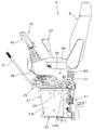
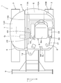
- reference numeral 1 denotes a backhoe exemplified as a work machine (a turning work machine).
- the work machine 1 includes a body (vehicle body) 2, a traveling device 3, and a work device 4.
- the cabin 20 is mounted on the body 2.
- the front side (left side in FIG. 40) of the driver seated in the driver's seat 8 of the cabin 20 is front
- the rear side (right side in FIG. 40) is back
- the left side (front side in FIG. 40) of the driver The left side and the right side of the driver (the back side in FIG. 40) will be described as the right side.
- the horizontal direction 7 (see FIG. 39), which is a direction orthogonal to the front-rear direction, will be described as the body width direction.
- the airframe 2 has a swivel base 6 supported on the frame of the traveling device 3.
- the swivel base 6 is supported through a bearing so as to be turnable to the left and right around a vertical axis.
- a work device 4 is attached to the right front portion of the swivel base 6. In FIG. 18, the working device 4 and the cabin 20 are omitted.
- the cabin 20 is mounted on the left part on the swivel base 6.
- a driver's seat 8 is provided inside the cabin 20.
- a left steering device 22 is provided on the left side of the driver's seat 8.
- a right steering device 23 is provided to the right of the driver's seat 8.
- a passenger entrance 20a is provided on the left side of the cabin 20 and on the left side of the driver's seat 8.
- a door 20A is provided at the entrance 20a.
- the engine room is provided at the rear of the swivel base 6.
- An engine E, a hydraulic pump, an air cleaner, and the like are arranged in the engine room.
- the front side of the engine room is partitioned from the driver's seat 8 by a partition wall 11A.
- the rear side of the engine room is covered with a rear bonnet 10A.
- the left side of the engine room is covered with a left cover body 10B.
- a tank room is provided on the right side of the turntable 6.
- a hydraulic oil tank T In the tank room, a hydraulic oil tank T, a control valve Q, a radiator, and the like are arranged.
- the left side of the tank room is partitioned from the driver's seat 8 by a partition wall 11B.
- the upper side, front side, and right side of the tank room are covered with the right cover body 10C.
- the working device 4 is attached to the front portion of the swivel base 6 via a support bracket 12 and a swing bracket 13.
- the support bracket 12 is fixed to the front portion of the swivel base 6.
- the swing bracket 13 is supported by the support bracket 12 so as to be swingable left and right around the vertical axis.
- the swing bracket 13 is swung left and right by a hydraulic swing cylinder.
- a counterweight W is attached to the rear part of the swivel base 6 in order to balance the weight with the working device 4.
- the traveling device 3 is a crawler type traveling device, and is provided on the right side and the lower left side of the body 2.
- the traveling device 3 is driven by a hydraulic traveling motor.
- a dozer 9 is provided at the front of the traveling device 3.
- the dozer 9 is swung up and down by a dozer cylinder comprising a hydraulic cylinder.
- the work device 4 includes a boom 14, an arm 15, and a work tool 16.
- the work device 4 includes a boom cylinder 17, an arm cylinder 18, and a work tool cylinder 19 as drive mechanisms (hydraulic actuators) for the boom 14 and the like.
- the boom cylinder 17, the arm cylinder 18 and the work tool cylinder 19 are constituted by double-acting hydraulic cylinders.
- the boom 14 is supported by the swing bracket 13 so as to be swingable in the vertical direction.
- the arm 15 is supported on the tip side of the boom 14 so that the base side can swing.
- the bucket as the work tool 16 is attached to the distal end side of the arm 15 so that a squeeze / dump operation is possible.
- a control unit S is provided on the swivel base 6. As shown in FIG. 18, the control section S is partitioned from the engine room by the partition wall 11A, and is partitioned from the tank room by the partition wall 11B.
- a driver's seat 8 is provided in the control unit S. As shown in FIGS.
- the driver's seat 8 includes a seat 8 ⁇ / b> A serving as a seat surface and a seat base 8 ⁇ / b> B provided below the seat 8 ⁇ / b> A.
- a left traveling operation lever SL and a right traveling operation lever SR are arranged in front of the driver seat 8.
- the left traveling operation lever SL and the right traveling operation lever SR By operating the left traveling operation lever SL and the right traveling operation lever SR, the left and right crawler traveling bodies 4 can be operated separately or simultaneously.
- Betals are arranged on the left and right feet of the driver's seat 8.
- a cockpit 21 is provided below the driver's seat 8.
- a left steering device 22 and a right steering device 23 are mounted on the control table 21.
- the left steering device 22 is provided on the left side of the driver's seat 8.
- the right steering device 23 is provided on the right side of the driver's seat 8.
- the control table 21 has a substantially flat upper surface portion 21A, a left leg portion 21L, and a right leg portion 21R.
- a storage space 21B having an open front surface is formed below the upper surface portion 21A and between the left leg portion 21L and the right leg portion 21R.
- the storage space 21B stores an air conditioner K1, an electric box K2, and the like.
- the electrical box K2 contains electrical parts for replacement (fuses, relays, etc.).
- the control table 21 is formed of, for example, two metal plates and includes a first member P1 and a second member P2.
- the first member P1 has mounting portions 21a and 21b on the upper surface portion 21A and a left leg portion 21L.
- the second member P2 has a placement portion 21c on the upper surface portion 21A and a right leg portion 21R.
- the first member P1 and the second member P2 are connected via bolts or the like.
- the right steering device 23 has a steering bracket 45.
- the control bracket 45 is provided with a right control valve (first valve) 46 and a work tool operation valve (second valve) 47.
- the steering bracket 45 has a vertical wall 45A and a mounting portion 45B.
- the vertical wall 45 ⁇ / b> A is erected on the cockpit 21.
- the mounting part 45B is fixed to the upper part of the mounting part 21c of the control table 21 with a bolt.
- the right steering valve 46 can be operated by a right operation lever 48.
- the work tool operation valve 47 can be operated by a work operation lever 49.
- the right steering valve 46 is a boom / bucket pilot valve, and the control valve for the boom cylinder 17 and the bucket cylinder 19 can be controlled by the right operation lever 48.
- the work tool operation valve 47 is a pilot valve for driving the dozer 9, and the work operation lever 49 can control the control valve for the dozer cylinder.
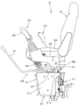
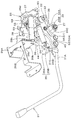
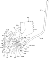
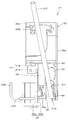
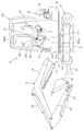
- the left steering device 22 includes a steering box 26, a cam body 33, and an unload lever 31.
- the steering box 26 is pivotally supported by the first horizontal shaft 27 with respect to the support bracket 25.
- the support bracket 25 has a mounting portion 25 ⁇ / b> A arranged in a horizontal direction and a support portion 25 ⁇ / b> B raised from the mounting portion 25 ⁇ / b> A.
- the mounting portion 25A is fixed to the mounting portion 21b of the control table 21.
- the control box 26 has a left plate member 26a, a right plate member 26b, a mounting plate 26c, and a bearing plate 26d, and is formed in a box shape.
- the left plate member 26 a forms the left side wall of the control box 26.
- the left plate member 26a is indicated by a virtual line (two-dot chain line).
- the right plate member 26b is bent in an L shape in plan view, and forms a right side wall and a back wall of the control box 26. The rear part of the left plate member 26a and the back wall of the right plate member 26b are fixed.
- the mounting plate 26c is fixed so as to connect the front portion of the left plate member 26a and the front portion of the right plate member 26b.
- the interval between the left plate member 26a and the right plate member 26b is narrower than the width of the mounting plate 26c.
- the bearing plate 26d is fixed to the inner surface (front surface) of the back wall of the left plate member 26b.
- the left surface of the bearing plate 26d faces the inner surface (right side surface) of the left plate material 26a.
- the right surface of the bearing plate 26d faces the inner surface (left side surface) of the right plate member 26b.
- a mounting portion 26 ⁇ / b> A for the left control valve 28 is formed on the mounting plate 26 c of the control box 26.
- the left steering valve 28 is mounted on the mounting portion 26A.
- the mounting portion 26A has a substantially semicircular opening 26B with the right front portion opened. Thereby, the left control valve 28 can be mounted on the opening 26B of the mounting portion 26A from the front right side on the driver's seat 8 side.
- the left control valve 28 is a pilot valve for turning and arm operation, and is operated by the left operation lever 30.
- the left operation lever 30 is attached to the upper part of the mounting portion 26 ⁇ / b> A of the control box 26.
- the support portion 25 ⁇ / b> B of the support bracket 25 is provided with a first horizontal shaft 27 and a first guide groove 24.
- the first horizontal axis 27 extends in the horizontal direction (machine width direction).
- the first guide groove 24 is provided above the first horizontal shaft 27.
- the first guide groove 24 includes a front groove 24A, an intermediate groove 24B, and a rear groove 24C.
- the front groove 24A extends upward and slightly forward from the front portion of the support portion 25B.
- the intermediate groove 24B extends rearward and slightly upward from the upper end of the front groove 24A.
- the rear groove 24C extends downward and slightly rearward from the rear end of the intermediate groove 24B.
- the lower end of the rear groove 24C is located slightly above the lower end of the front groove 24A.
- a second guide pin 44 described later is inserted into the first guide groove 24.
- the front groove 24A functions as a first locking portion that locks the second guide pin 44 on one side (front side) of the first guide groove 24.
- the rear groove 24B functions as a second locking portion that locks the second guide pin 44 on the other side (rear side) of the first guide groove 24.
- a boss portion 26 ⁇ / b> C is provided at the lower rear portion of the control box 26.
- the boss portion 26C extends in the lateral direction (machine width direction) so as to connect the left plate member 26a and the bearing plate 26d.
- the boss portion 26 ⁇ / b> C is rotatably fitted on the outer periphery of the first horizontal shaft 27. Thereby, the control box 26 is rotatably supported with the first horizontal shaft 27 as a fulcrum (around the first horizontal shaft 27).
- a second horizontal shaft 32 extending in the horizontal direction (machine width direction) is provided at the rear of the control box 26.
- the second horizontal axis 32 is located behind the first horizontal axis 27 and behind the first guide groove 24.
- a base portion (rear portion) of the cam body 33 is pivotally supported at the rear portion of the control box 26 via a second horizontal shaft 32.
- the cam body 33 extends forward and downward from the second horizontal shaft 32.
- a base portion (a lever base portion 31B described later) of the unload lever 31 is pivotally supported via a third horizontal shaft 36 at a lower portion (a pivot supporting portion 51 described later) of the cam body 33.
- the unload lever 31 is swingably supported by the control box 26 via the cam body 33.
- the unload lever 31 can be operated by supplying the hydraulic oil to the hydraulic actuator of the work device 4 by the swing.
- the cam body 33 has a cam groove 34 formed from one side (rear part) to the other side (front part).
- the support portion 25B of the support bracket 25 is provided with a first guide pin 35 having an axis extending in the body width direction.
- the first guide pin 35 is located in front of the first horizontal shaft 27 and at an intermediate height between the second horizontal shaft 32 and the first horizontal shaft 27. Further, as shown in FIG.
- the first guide pin 35 is located between the front groove 24A and the rear groove 24C of the first guide groove 24 and below the intermediate groove 24B.
- the first guide pin 35 is inserted into the cam groove 34 via a cam follower.
- the cam body 33 and the like are omitted.
- the cam groove 34 has a first cam groove 34A and a second cam groove 34B.
- the first cam groove 34 ⁇ / b> A is formed on one side (rear part) of the cam body 33.
- the second cam groove 34 ⁇ / b> B is formed on the other side (front portion) of the cam body 33. Specifically, the second cam groove 34 ⁇ / b> B extends forward from the front end portion of the first cam groove 34.
- the first cam groove 34 ⁇ / b> A is formed in an arc shape centered on the axis of the second horizontal shaft 32.
- the second cam groove 34B is formed to have an arc shape centered on the axis of the first horizontal shaft 27 when the first guide pin 35 is in the second cam groove 34B (see FIGS. 13 to 15).
- the cam groove 34 is formed to have a length that allows the control box 26 to rotate around a required angle, for example, about 50 °.
- the cam body 33 has the second horizontal shaft 32 as a fulcrum (around the second horizontal shaft 32), and one (upward) ).
- the cam body 33 rotates, the position of the first guide pin 35 changes within the cam groove 34.
- the cam groove 34 moves relatively from one (rear) to the other (front). More specifically, it moves relatively from the first cam groove 34A to the second cam groove 34B. That is, when the unload lever 31 is in the pushed down position (see FIG.
- the first guide pin 35 is located in the first cam groove 34A on one side (rear side) of the cam groove 34 and is in the raised position ( 13) is located in the second cam groove 34B on the other (front) side of the cam groove. The movement of the first guide pin 35 will be described in detail later.
- a stay 37 having a substantially L-shaped side view is fixed to the upper surface of the rear portion (base portion) of the cam body 33.
- a return spring 38 as an urging member is interposed between the upper portion of the stay 37 and the mounting plate 26c of the control box 26.
- the upper portion of the stay 37 can come into contact with a stopper 54 (see FIG. 8) provided on the right plate member 26a.
- the unload lever 31 is urged by the return spring 38 in the push-down direction (counterclockwise direction in FIG. 9).
- a locking plate 53 that locks one end of a tension spring 50 as an urging member described later is fixed to the front portion of the stay 37.
- the cam body 33 has two through holes penetrating from one surface to the other surface.
- the rear through hole constitutes a pivot portion 51 on which a third horizontal shaft 36, which will be described later, is pivotally supported.
- the front through hole constitutes a second guide groove 52 that guides the movement of the third guide pin 40 described later.
- the second guide groove 52 is composed of a long hole provided in front of the pivotal support portion 51.
- the second guide groove 52 is formed in a substantially elliptical shape that is long in the vertical direction, and has an upper first position 52A and a lower second position 52B. A third guide pin 40 described later is inserted into the second guide groove 52.
- the unload lever 31 has a lever body 31A and a lever base 31B.
- the lever main body 31 ⁇ / b> A is a part that is gripped when the driver operates the unload lever 31.
- the rear end portion of the lever main body 31A is fixed to the front portion of the lever base portion 31B.
- the lever main body 31 ⁇ / b> A extends from the front portion of the lever base portion 31 ⁇ / b> B toward the front upper side of the control box 26.
- the lever base 31B is formed of a plate-like member, and is arranged with one surface facing the right side (the support portion 25B side of the support bracket 25) and the other surface facing the left side (the cam body 33 side). Has been. That is, the lever base portion 31B is disposed between the support portion 25B of the support bracket 25 and the cam body 33 in the body width direction. As shown in FIGS. 5 and 12, the lever base 31 ⁇ / b> B has a third horizontal shaft 36, a second guide pin 44, and a third guide pin 40.
- the third horizontal shaft 36 is provided at the lower rear portion of the lever base 31B and protrudes toward the left (cam body 33 side).
- the third horizontal shaft 36 is located in front of the first horizontal shaft 27 and below the cam groove 34.
- the third horizontal axis 36 is located behind the third guide pin 40.
- the third horizontal axis 36 is a bolt in this embodiment.
- the second guide pin 44 is provided at the upper rear portion of the lever base portion 31B and protrudes toward the right side (the support portion 25B side).
- the second guide pin 44 is provided above the third horizontal shaft 36.
- the protruding end (right end) of the second guide pin 44 is inserted into the first guide groove 24 and can move in the first guide groove 24 from the front groove 24A to the rear groove 24C.
- the second guide pin 44 When the second guide pin 44 is positioned in the front groove (first locking portion) 24A of the first guide groove 24, the second guide pin 44 is locked in the front groove 24A, and the rear groove (second locking portion) 24C. When positioned, it is locked in the rear groove 24C.
- the third guide pin 40 is provided at the front lower portion of the lever base 31B and protrudes toward the left (cam body 33 side).
- the third guide pin 40 is provided below and in front of the second guide pin 44.
- the 3rd guide pin 40 consists of a stepped volt
- a concave notch 31b that is notched forward is formed at the rear of the lever base 31B. By forming the notch 31b, it is possible to prevent the first guide pin 35 from interfering with the lever base 31B when it moves along the cam groove 34.
- the lever base portion 31B is provided with a locking portion 31C for locking one end portion of the biasing member (tensile spring) 50.
- the locking portion 31C extends upward from the front upper portion of the lever base portion 31B.
- the pivotal support portion 51 is positioned in front of the first guide pin 35, below the second guide pin 44, and behind the third guide pin 40.
- the unload lever 31 (the lever main body 31A and the lever base portion 31B) is rotatable with respect to the cam body 33 with the pivot portion 51 (the third horizontal shaft 36) as a fulcrum.
- the second guide groove 52 is inserted with a shaft portion of a bolt constituting the third guide pin 40.
- the outer diameter of the head portion of the bolt constituting the third guide pin 40 is larger than the inner diameter of the second guide groove 52, and the head portion is located on the outer surface (left surface) of the cam body 33 on the left outside the second guide groove 52. ).
- the third guide pin 40 has one of the second guide grooves 52 (first position 52A) when the unload lever 31 (the lever main body 31A and the lever base 31B) is rotated downward with the third horizontal shaft 36 as a fulcrum. ) To the other (second position 52B), and when rotated upward, moves from the other (second position 52B) to one (first position 52A).
- the third guide pin 40 has one of the second guide grooves 52 (first position 52A) when the unload lever 31 is in the upward rotation position (first position) with the third horizontal shaft 36 as a fulcrum.
- the second guide groove 52 is located on the other side (second position 52B) when in the downward rotation position (second position).
- the rotation range around the third horizontal shaft 36 of the unload lever 31 is the upper limit position when the third guide pin 40 is at the first position 52A, and the third guide pin 40 is at the second position 52B. At some point, it is the lower limit position. In other words, the rotation range of the unload lever 31 around the third horizontal axis 36 is restricted by the second guide groove 52.
- a tension spring 50 as an urging member is interposed between the locking portion 31 ⁇ / b> C of the lever base portion 31 ⁇ / b> B and the locking plate 53. The tension spring 50 biases the unload lever 31 in a direction in which the unload lever 31 is rotated upward with the third horizontal shaft 36 as a fulcrum.
- the unload lever 31 is rotated upward by the urging force of the tension spring 50 with the third horizontal shaft 36 as a fulcrum, and this rotation is performed by the third guide pin 40 at the first position 52A of the second guide groove 52. It stops when it reaches.
- the third guide pin 40 moves from the first position 52A to the second position 52B.
- a rotation detection device 55 including a limit switch is provided on the upper portion of the bearing plate 26d of the control box 26.
- the switch piece at the tip of the rotation detection device 55 is engaged with the stay 37.
- the rotation detection device 55 is connected to the electronic control units of the left steering device 22 and the right steering device 23.
- the rotation detection device 55 operates an unload valve provided in the hydraulic circuit of each of the control devices 22 and 23 by being turned off from on.
- a gas cylinder (gas spring) 39 as an urging member is provided between the support portion 25B of the support bracket 25 and the control box 26.
- the gas cylinder 39 connects a pin 39a projecting from the front lower portion of the support portion 25B and a pin 39b projecting from an upper position of the control box 26.
- the gas cylinder 39 has an urging force in the extending direction, and assists in turning the left steering device 22 upward. Headed pins are used as the pins 39a and 39b. Thereby, securing of the mounting strength of the gas cylinder 39 and facilitation of disassembly and assembly are achieved.
- the first contact mechanism 41 is provided on the support portion 25 ⁇ / b> B of the support bracket 25.
- the first contact mechanism 41 holds the left steering device 22 in a use position (see FIGS. 8 to 11) described later.
- the first contact mechanism 41 includes a mounting plate 41A fixed to the upper portion of the support portion 25B, and a first contact member 41B attached to the mounting plate 41A.
- the first contact member 41B contacts the first contact plate 70 fixed to the right plate member 26b of the control box 26 when the left steering device 22 is in the use position.
- a second contact mechanism 42 is provided on the mounting portion 25A of the support bracket 25.
- the second contact mechanism 42 holds the left steering device 22 in an upward rotation position (avoidance position) (see FIG. 13) described later.
- the second contact mechanism 42 includes an attachment plate 42A fixed to the rear portion of the attachment portion 25A, and a second contact member 42B attached to the attachment plate 42A.
- the second contact member 42B contacts the second contact plate 56 fixed to the left plate member 26a of the control box 26 when the left control device 22 is in an upward rotation position (see FIG. 13) described later.
- a guide member 43 is provided on the surface (right side surface) of the support bracket 25 on the driver's seat 8 side.
- the guide member 43 guides the hose connected to the left steering valve 28.
- the guide member 43 protrudes toward the driver's seat 8 from the mounting portion 25A of the support bracket 25.
- the first horizontal shaft 27, the cam body 33, the unload lever 31, the return spring 38, the rotation detection device 55, the first contact mechanism 41, the second contact mechanism 42, and the like constitute the rotation mechanism 29. ing.
- the left steering device 22 is rotated upward (withdrawn) by the turning mechanism 29, the entrance 20a on the left front side of the driver's seat 8 (that is, the front side of the left steering device 22) is widely secured. It is avoided that the left steering device 22 prevents the driver from getting on and off.
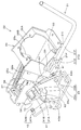
- FIGS. 8 to 11 show a state in which the unload lever 31 is in the pushed down position.
- the states shown in FIGS. 8 to 11 are used positions (normal work positions) when working with the work implement 1.
- the first abutment mechanism 41 restricts the downward rotation of the control box 26 around the first horizontal axis 27, and the left control device 22 is held in the use position.
- the left steering device 22 is held at the use position.
- the first guide pin 35 is located at the base end (rear end) of the first cam groove 34A.
- the second guide pin 44 is locked to the front groove (first locking portion) 24 ⁇ / b> A of the first guide groove 24.
- the unload lever 31 is restricted from rotating downward (the counterclockwise direction in FIG. 9 and the clockwise direction in FIG. 11) by the first locking portion 24A and the stopper 54.
- the rotation detection device 55 is on, and the upward rotation of the unload lever 31 is not detected. That is, the unload lever 31 is in the unload release position.
- the left operation lever 30 for the turning / arm by operating the left operation lever 30 for the turning / arm, the turning of the turntable 6 and the raising / lowering of the arm 15 can be activated, and the operation by the right steering device 23 for the boom / bucket. Is enabled. ⁇ The unload lever is in the raised position> Next, a state where the unload lever 31 is in the lifted position will be described.
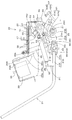
- FIG. 13 shows a state where the unload lever 31 is in the lifted position.
- the state shown in FIG. 13 is the upward rotation position (avoidance position).
- the left steering device 22 is held in the upward rotation position by the second contact member 42B of the second contact mechanism 42 coming into contact with the second contact plate 56 fixed to the left plate member 26a.
- the rotation detection device 55 is turned off, and the unload state by the unload lever 31 is detected. That is, the unload lever 31 is in the unload position.
- the left operation lever 30 for the turn / arm is operated, the turntable 6 and the arm 15 are disabled.
- the boom 14 and the bucket 16 are disabled.
- the unload lever 31 is urged by the urging force of the tension spring 50 in a direction of rotating upward with the third horizontal shaft 36 as a fulcrum. Therefore, the third guide pin 40 provided on the lever base 31 ⁇ / b> B of the unload lever 31 is held at the first position 52 ⁇ / b> A above the second guide groove 52.
- the first guide pin 35 is located near the front end of the second cam groove 34B.
- the second guide pin 44 is locked to the rear groove (second locking portion) 25 ⁇ / b> C of the first guide groove 24. Since the second guide pin 44 is provided on the lever base 31B of the unload lever 31, it cannot be separated from the rear groove (second locking portion) 25C unless the unload lever 31 is operated.
- the control box 26 cannot be rotated downward without holding the unload lever 31 (locked state).
- the driver is prevented from depressing a portion other than the unload lever 31 (the left operation lever 30 or the like) to enter the unload release state (load state).
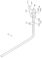
- ⁇ Operation of the left control device when the unload lever is pushed down> ⁇ First stage>
- the driver slightly pushes down the unload lever 31 against the urging force of the tension spring 50. Specifically, as shown in FIG. 14, the unload lever 31 is moved from the first position (the third guide pin 40 is in the first position 52A) to the second position (the third guide pin 40 is in the second position 52B).
- the first guide pin 35 moves to the vicinity of the boundary between the second cam groove 34B and the first cam groove 34A.
- the second guide pin 44 moves to the vicinity of the boundary between the intermediate groove 24B of the first guide groove 24 and the front groove (first locking portion) 24A.
- the control box 26 further rotates downward.
- ⁇ Fourth stage> When the unload lever 31 is further pushed down from the state of FIG. 16, the cam body 33 further rotates downward as shown in FIG.
- the first guide pin 35 moves upward along the first cam groove 34A.
- the second guide pin 44 moves downward along the front groove (first locking portion) 24 ⁇ / b> A of the first guide groove 24.
- the second guide pin 44 when the unload lever 31 is in the lifted position, the second guide pin 44 has the rear groove (second locking portion) 24C of the first guide groove 24.
- the control box 26 is prevented from turning downward (locked state). As a result, it is possible to prevent the driver from inadvertently depressing a portion other than the unload lever 31 (such as the left operation lever 30) to enter the load state.
- the unload lever 31 is rotated downward to move the third guide pin 40 from the first position 52A to the second position 52B, whereby the second guide pin 44 moves above the first guide groove 24 and is separated from the rear groove (second locking portion) 24C, and the locked state is released. That is, the locked state is not released unless the driver performs an operation of pushing down the unload lever 31. For this reason, it is possible to reliably prevent the driver from turning down the steering box 26 into a loaded state by pushing down a portion other than the unload lever 31 (such as the left operation lever 30). Further, when releasing the locked state, a special unlocking operation is not required other than the pushing-down operation of the unload lever 31, so that the operability is excellent.
- a biasing member (a tension spring 50) that biases the unload lever 31 in a direction in which the unload lever 31 is rotated upward with the third horizontal shaft 36 as a fulcrum (a direction in which the unload lever 31 is held at the first position).
- the locked state can be reliably maintained. That is, unless the driver pushes down the unload lever 31 against the biasing member (the tension spring 50), the third guide pin 40 is maintained at the first position 52A. (Second engagement portion) The state (locked state) engaged with 24C is reliably maintained.
- Second Embodiment are views showing a second embodiment of the present invention.
- the basic configuration of the work machine 1 shown in FIGS. 1, 2, 39, and 40 is common to the first embodiment and the second embodiment.
- the second embodiment will be described focusing on the configuration different from the first embodiment.
- symbol is attached
- subjected and description is abbreviate
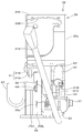
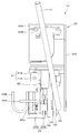
- the left steering device 22 of the second embodiment includes a steering box 26, a cam body 80, and an unload lever 31.
- the control box 26 is pivotally supported with respect to the support bracket 25.
- the support bracket 25 has a mounting portion 25A arranged in a horizontal direction and a support portion 25B raised from the mounting portion 25A.
- the mounting portion 25A is fixed to the upper surface portion 21A of the control table 21.
- the control box 26 includes a left plate member 26a, a right plate member 26b, a mounting plate 26c, and a bearing plate 26d, and is formed in a box shape.
- the left plate member 26 a forms the left side wall of the control box 26.
- the left plate member 26a is indicated by a virtual line (two-dot chain line), and in FIG. 24, the left plate member 26a is omitted.
- the support portion 25B of the support bracket 25 is provided with a first horizontal shaft 27 extending in the lateral direction (machine width direction).
- a boss portion 26 ⁇ / b> C is provided at the lower rear portion of the control box 26.
- the boss portion 26C extends in the lateral direction (machine width direction) so as to connect the left plate member 26a and the bearing plate 26d.
- the boss portion 26 ⁇ / b> C is rotatably fitted on the outer periphery of the first horizontal shaft 27.
- the control box 26 is rotatably supported with the first horizontal shaft 27 as a fulcrum (around the first horizontal shaft 27).
- a fourth guide pin 61 having a shaft center extending in the body width direction is projected on the support portion 25B of the support bracket 25, a fourth guide pin 61 having a shaft center extending in the body width direction is projected.
- the fourth guide pin 61 is located in front of the first horizontal shaft 27 and at an intermediate height between the second horizontal shaft 32 and the first horizontal shaft 27.
- a second horizontal shaft 32 extending in the horizontal direction (machine width direction) is provided at the rear portion of the control box 26.
- the second horizontal axis 32 is located on the rear upper side of the first horizontal axis 27.
- a base portion (rear portion) of the cam body 80 is pivotally supported at the rear portion of the control box 26 via the second horizontal shaft 32.
- the cam body 80 extends forward and downward from the second horizontal shaft 32.
- a base portion (rear portion) of the unload lever 31 is fixed to the front portion of the cam body 80.
- the unload lever 31 is swingably supported by the control box 26 via the cam body 80.
- the unload lever 31 can be operated by supplying the hydraulic oil to the hydraulic actuator of the work device 4 by the swing.
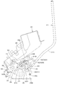
- the cam body 80 has a cam groove 81 formed from one side (rear part) to the other side (front part).
- the cam groove 81 is provided in front of the second horizontal shaft 32 (on the unload lever 31 side).
- the fourth guide pin 61 is inserted into the cam groove 81 via a cam follower.
- the cam groove 81 is formed to have a length that allows the control box 26 to rotate around a necessary angle, for example, about 50 °.
- the cam groove 81 has an intermediate groove part 81a, a rear groove part 81b, and a front groove part 81c.
- the intermediate groove 81a is formed so as to go from one side (rear part) of the cam body 80 to the other side (front part).
- the intermediate groove 81a has an arc shape centered on the axis of the first horizontal shaft 27 in a state where the fourth guide pin 61 is positioned in the intermediate groove 81a (see FIGS. 25 to 27). Is formed.
- the rear groove portion 81b is formed in an arc shape centering on the axis of the second horizontal shaft 32 so as to extend upward from the rear end portion of the intermediate groove portion 81a.
- the front groove portion 81c is formed to extend downward from the front end portion of the intermediate groove portion 81a.
- the cam groove 81 is formed in a substantially Z shape in a side view by the intermediate groove portion 81a, the rear groove portion 81b, and the front groove portion 81c.
- the widths of the intermediate groove portion 81 a and the rear groove portion 81 b are formed to be approximately equal to the diameter of the fourth guide pin 61.
- the front groove portion 81 c has a widened portion 81 e that is formed wider than the diameter of the fourth guide pin 61.
- the widened portion 81e is formed by extending the rear portion of the inner edge of the front groove portion 81c rearward in an arc shape, and the portion expanded in the arc shape has a locking recess 81f to which the fourth guide pin 61 is locked. It is composed. Since the front groove portion 81c has the widened portion 81e, as shown in FIG. 28, the outer periphery of the fourth guide pin 61 and the front groove portion 81c are in a state where the fourth guide pin 61 is locked to the locking recess 81f. A gap G is formed between the inner edge.
- the cam body 80 rotates about the second horizontal shaft 32 (around the second horizontal shaft 32) and on one side (upward). Move. As the cam body 80 rotates, the position of the fourth guide pin 61 changes within the cam groove 81. More specifically, the cam groove 81 moves relatively from one side to the other side (specifically, from the rear groove portion 81b to the front groove portion 81c via the intermediate groove portion 81a). When the unload lever 31 is pushed down, the fourth guide pin 61 moves relatively in the cam groove 81 from the other side to the other side (specifically, from the front groove portion 81c to the rear groove portion 81b via the intermediate groove portion 81a). Moving.
- the fourth guide pin 61 is located in one of the cam grooves 81 (rear groove portion 81b).
- the fourth guide pin 61 is positioned on the other side of the cam groove 81 (front groove portion 81c).
- the fourth guide pin 61 is located between one and the other of the cam grooves 81 (intermediate groove 81a).
- a stay 37 having a substantially L shape in a side view is fixed on the upper surface of the rear portion (base portion) of the cam body 80.
- the upper portion of the stay 37 can come into contact with a stopper 54 (see FIG. 24, etc.) provided on the right plate member 26a.
- the cam body 80 has a fifth guide pin 62 extending in the lateral direction (machine body width direction) at the front lower side of the first horizontal shaft 27.
- the fifth guide pin 62 protrudes below the front groove portion 81 c of the cam groove 81.
- a fourth horizontal shaft 63 extending in the lateral direction (machine width direction) is provided at the front lower portion of the support portion 25B of the support bracket 25.
- the fourth horizontal axis 63 is located in front of the first horizontal axis 27 and in front of the fifth guide pin 62. Further, the fourth horizontal shaft 63 is located in the lower front side of the cam groove 81.
- a cam link 64 is pivotally supported on the front lower portion of the support portion 25 ⁇ / b> B of the support bracket 25 via a fourth horizontal shaft 63.
- the cam link 64 has a locking portion 64 ⁇ / b> A that is locked to the fifth guide pin 62.
- the locking portion 64A is formed of a substantially U-shaped notch in a side view.
- the fifth guide pin 62 moves relative to the notch of the locking portion 64A when the cam link 64 rotates about the fourth horizontal shaft 63 (around the fourth horizontal shaft 63). That is, the fifth guide pin 62 itself does not move, but the fifth guide pin 62 moves inside the notch of the locking portion 64A by moving the locking portion 64A.
- the cam link 64 rotates in conjunction with the rotation of the cam body 80 via the fifth guide pin 62 when the locking portion 64A is locked to the fifth guide pin 62.
- the cam body 80 rotates downward in conjunction with the rotation of the cam link 64 in one direction around the fourth horizontal axis 63.
- the cam body 80 rotates upward in conjunction with the rotation of the cam link 64 in the other direction opposite to the one direction.
- the one direction is a direction in which the locking portion 64A of the cam link 64 descends, and is the clockwise direction in FIG.
- the other direction is a direction in which the locking portion 64A of the cam link 64 moves upward, and is the counterclockwise direction in FIG.
- An urging member 82 made of a gas cylinder is provided between the cam link 64 and the control box 26.
- the urging member 82 connects a pin 82 a projecting from the cam link 64 and a pin 82 b projecting closer to the upper portion of the control box 26.
- the urging member 82 has an urging force in the extending direction, and assists in turning the left steering device 22 (the steering box 26) upward.
- the cam link 64 and the fifth guide pin 62 are configured such that the direction of the urging force by the urging member 82 is a direction in which the cam body 80 is rotated to one side (upward) (hereinafter also referred to as a first direction).
- a switching mechanism for switching to the other (downward) direction (hereinafter also referred to as the second direction) is configured.
- the urging direction by the urging member 82 is the first direction when the fourth guide pin 61 is in one of the cam grooves 81 (rear groove portion 81b), and the fourth guide pin 61 is the other of the cam grooves 81.
- the second direction is set.
- the urging member 82 rotates the cam link 64 in the one direction (the clockwise direction in FIG. 23) when the fourth guide pin 61 is in one of the cam grooves 81 (rear groove 81b). Give the urging force to move.
- the urging force for rotating the cam link 64 in one direction is transmitted to the cam body 80 via the fifth guide pin 62, and in the direction (second direction) for rotating the cam body 80 in the other direction (downward). It becomes an energizing force.
- the urging member 82 is attached to rotate the cam link 64 in the other direction (counterclockwise direction in FIG. 23). Grant power.
- the urging force for rotating the cam link 64 in the other direction is transmitted to the cam body 80 via the fifth guide pin 62, and in the direction (first direction) for rotating the cam body 80 in one direction (upward). It becomes an energizing force.
- the fourth guide pin 61 is locked to the locking recess 81f of the front groove 81c.
- a rotation detection device 55 including a limit switch is provided on the upper part of the bearing plate 26d fixed to the right plate member 26a of the control box 26, a rotation detection device 55 including a limit switch is provided.
- the switch piece at the tip of the rotation detection device 55 is engaged with the stay 37.
- the rotation detection device 55 is connected to the electronic control units of the left steering device 22 and the right steering device 23.
- the rotation detection device 55 operates an unload valve provided in the hydraulic circuit of each of the control devices 22 and 23 by being turned off from on.
- a first contact mechanism 41 is provided on the support portion 25 ⁇ / b> B of the support bracket 25.
- the first contact mechanism 41 holds the left steering device 22 at a use position (see FIGS. 22 and 23) described later.
- the first contact mechanism 41 includes a mounting plate 41A fixed to the upper portion of the support portion 25B, and a first contact member 41B attached to the mounting plate 41A.
- the first contact member 41B contacts the first contact plate 70 fixed to the right plate member 26b of the control box 26 when the left steering device 22 is in the use position.
- the mounting portion 25A of the support bracket 25 is provided with a second contact mechanism.
- the second contact mechanism 42 holds the left steering device 22 in an upward rotation position (avoidance position) (see FIG. 28) described later.
- the second contact mechanism 42 includes an attachment plate 42A fixed to the rear portion of the attachment portion 25A, and a second contact member 42B attached to the attachment plate 42A.
- the second contact member 42B contacts the second contact plate 56 fixed to the left plate member 26a of the control box 26 when the left control device 22 is in the upward rotation position (see FIG. 28).
- first horizontal shaft 27, cam body 80, unload lever 31, rotation detection device 55, first contact mechanism 41, second contact mechanism 42, and the like rotate the left steering device 22. 29 is configured.
- the left steering device 22 is rotated upward (withdrawn) by the turning mechanism 29, the entrance 20a on the left front side of the driver's seat 8 (that is, the front side of the left steering device 22) is widely secured.
- the left steering device 22 does not prevent the driver from getting on and off.
- the left steering device 22 is in a use position (normal work position) when working with the work machine 1 in the state shown in FIGS.
- the first abutment mechanism 41 restricts the downward rotation of the control box 26 around the first horizontal axis 27, and the left control device 22 is held in the use position.
- the left steering device 22 is held at the use position.
- the fourth guide pin 61 is located at the base end (rear end) of the rear groove portion 81 b of the cam groove 81. Further, the unload lever 31 is restricted by the stopper 54 from turning downward (counterclockwise in FIG. 23). In this use position, the rotation detection device 55 is on, and the upward rotation of the unload lever 31 is not detected. That is, the unload lever 31 is in the unload release position. In this state, by operating the left operation lever 30 for the turning / arm, the turning of the turntable 6 and the raising / lowering of the arm 15 can be activated, and the operation by the right steering device 23 for the boom / bucket. Is enabled.
- the cam body 80 fixed to the unload lever 31 is also rotated upward.
- the fourth guide pin 61 moves relative to the cam body 80 and moves in the cam groove 81 from the rear part to the front part.
- the fourth guide pin 61 first moves from the base end (rear end) of the rear groove portion 81b to the rear portion of the intermediate groove portion 81a, and the arc groove centered on the axis of the first horizontal shaft 27. Is engaged with the intermediate groove 81a. Thereby, the upper rotation of the control box 26 around the first horizontal axis 27 is allowed, and the rotation is started.
- the fourth guide pin 61 moves from the rear part of the intermediate groove part 81a to the middle part. From the state (first stage) where the fourth guide pin 61 shown in FIG. 25 is at the proximal end (rear end) of the rear groove part 81b to the state (second stage) where it is in the middle part of the intermediate groove part 81a shown in FIG.
- the cam link 64 rotates in the other direction (counterclockwise direction in FIGS. 23, 25, and 26) with the fourth horizontal shaft 63 as a fulcrum.
- the cam body 80 rotates upward with the second horizontal shaft 32 as a fulcrum.
- the fourth guide pin 61 moves from the front part of the intermediate groove part 81a to the front groove part 81c.
- the cam link 64 uses the fourth horizontal shaft 63 as a fulcrum in the other direction (counterclockwise in FIGS. 23, 25, and 26). Direction).
- the cam body 80 rotates upward with the second horizontal shaft 32 as a fulcrum.
- Rotation detection device 55 is turned off when the control box 26 is rotated upward from the position (use position) shown in FIG. 23 and detects the unload state by the unload lever 31. After the unload lever 31 is in the unloaded state, the left steering device 22 is further rotated upward together with the control box 26, so that the left steering device 22 passes through the position shown in FIGS. 25 to 27 and then the upward rotation shown in FIG. Position (avoidance position). In this upward rotation position, the left steering device 22 is retracted upward so as to widen the entrance 20.
- the swivel base 6 and the arm 15 cannot be operated even if the left operation lever 30 for the turn / arm is operated. Further, even if the right steering device 23 for the boom / bucket is operated, the boom 14 and the bucket 16 are disabled. In the operation of pulling up the unload lever 31 from the use position to the upward rotation position (avoidance position), the urging member 82 extends. The urging member 82 assists the operation of rotating the control box 26 upward around the first horizontal axis 27 until it reaches the maximum extended state.
- the biasing member 82 applies a biasing force that rotates the cam link 64 around the fourth horizontal shaft 63 in the process of pulling up the unload lever 31 from the use position to the upward rotation position (avoidance position). is doing. Specifically, the urging member 82 applies an urging force that rotates the cam link 64 in the one direction when the fourth guide pin 61 is in the front groove portion 81c. On the other hand, when the fourth guide pin 61 is in the rear groove 81b, an urging force for rotating the cam link 64 in the other direction is applied. That is, the urging member 82 changes the direction of the urging force with respect to the cam link 64 in the process in which the fourth guide pin 61 moves from the rear part to the front part of the intermediate groove part 81a.
- the rotation direction of the cam link 64 changes (reverse rotation), and the rotation direction of the cam body 80 interlocks with the change (reverse rotation) of the cam link 64. Will also change (reverse).
- the change in the biasing direction of the biasing member 82 is caused by a change in the positional relationship between the pins 82a and 82b at both ends of the biasing member 82. 23, 25, and 26, when the pin 82a is located behind the pin 82b, the urging member 82 attaches the cam link 64 to the other direction (direction in which the locking portion 64A is lowered). Rush. On the other hand, as shown in FIGS.
- the urging member 82 urges the cam link 64 in the one direction (direction in which the locking portion 64A rises). To do.
- the change in the positional relationship between the pins 82a and 82b occurs in the process in which the fourth guide pin 61 moves from the rear part to the front part of the intermediate groove part 81a.
- the left steering device 22 (control box 26) reaches the upward rotation position (avoidance position)
- the second contact member 42B is fixed to the left plate member 26a.
- the left steering device 22 (steering box 26) is held at the avoidance position.
- the fourth guide pin 61 is in the front groove portion 81c.
- the urging member 82 urges the cam link 64 in the one direction (the direction in which the locking portion 64A rises). This urging force is transmitted to the cam body 80 via the fifth guide pin 62.
- the unloading lever 31 is biased by the biasing member 82 (see FIG. 28) from the state where the left steering device 22 (the steering box 26) is in the upward rotation position (see FIG. 28). Press down a little against the force to stretch). As a result, the cam body 80 rotates downward with the second horizontal shaft 32 as a fulcrum. By this rotation, the fourth guide pin 61 moves from the locking recess 81f of the front groove 81c to the intermediate groove 81a, and the locked state is released (see FIG. 27). As a result, the unload lever 31 can be further pushed down.
- the steering box 26 rotates downward, and the left steering device 22 becomes the use position as shown in FIG. Thereby, the rotation detection device 55 is turned on, and the unload state is not detected. That is, the unload release state is established.
- the left operation lever 30 for the turning / arm by operating the left operation lever 30 for the turning / arm, the turning of the turntable 6 and the raising / lowering of the arm 15 can be operated, and the operation by the right control device 23 for the boom / bucket can be performed. Operable.
- the urging force of the urging member 82 causes the fourth guide pin 61 to move into the locking recess 81f of the front groove portion 81c. It is held in the locked state (locked state), and the downward rotation of the control box 26 is prevented. As a result, it is possible to prevent the driver from inadvertently depressing the left operation lever 30 to enter the unload release state.
- the unload lever 31 is pushed down against the urging force of the urging member 82 to disengage the fourth guide pin 61 from the locking recess 81f of the front groove portion 81c.
- the lock state is released with. That is, when the driver is not performing an operation for releasing the locked state, since the downward rotation of the control box 26 is prevented, the driver cannot push down the left operation lever 30. Therefore, it is possible to reliably prevent the driver from inadvertently depressing the left operation lever 30 to enter the unload release state. In addition, when releasing the locked state, no special operation is required other than the push-down operation of the unload lever 31, so that the operability is excellent.
- the driver depresses the unload lever 31 against the urging force of the urging member 82, the state where the fourth guide pin 61 is locked to the front groove portion 81c by the urging force of the urging member 82 is maintained. Therefore, the locked state is reliably maintained.
- the biasing member 82 applies a biasing force that rotates the cam link 64 in the one direction. This urging force acts as a force for rotating the cam body 80 downward. Thereby, the unload lever 31 is urged in the push-down direction (counterclockwise direction in FIG. 23).
- the urging member 82 can be easily assembled. That is, when the urging member 82 such as a gas cylinder is assembled, the urging member 82 must be assembled while being shortened against the urging force (force to be extended). Therefore, the biasing member 82 is assembled in the most extended state (see FIG. 28) so that the degree of shortening is reduced. In this state, since the fourth guide pin 61 is located in the front groove portion 81c, it becomes play when the widened portion 81e is assembled. Therefore, the urging member 82 can be easily assembled.
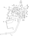
- the left steering device 22 of the third embodiment includes a steering box 26, a cam body 90, and an unload lever 31.
- the control box 26 is pivotally supported with respect to the support bracket 25.
- the support bracket 25 includes a mounting portion 25A arranged in a horizontal direction and a support portion 25B raised from the mounting portion 25A.
- the mounting portion 25A is fixed to the upper surface portion 21A of the control table 21.
- the control box 26 includes a left plate member 26a, a right plate member 26b, a mounting plate 26c, and a bearing plate 26d, and is formed in a box shape.
- the left plate member 26 a forms the left side wall of the control box 26.
- the left plate member 26a is indicated by a virtual line (two-dot chain line), and the left plate member 26a is omitted in FIG.
- the support portion 25B of the support bracket 25 is provided with a first horizontal shaft 27 extending in the lateral direction (machine width direction).
- a boss portion 26 ⁇ / b> C is provided at the lower rear portion of the control box 26.
- the boss portion 26C extends in the lateral direction (machine width direction) so as to connect the left plate member 26a and the bearing plate 26d.
- the boss portion 26 ⁇ / b> C is rotatably fitted on the outer periphery of the first horizontal shaft 27.
- the control box 26 is rotatably supported with the first horizontal shaft 27 as a fulcrum (around the first horizontal shaft 27).
- a second horizontal shaft 32 extending in the horizontal direction (machine width direction) is provided at the rear of the control box 26.
- the second horizontal axis 32 is located on the rear upper side of the first horizontal axis 27.
- a base portion (rear portion) of the cam body 90 is pivotally supported at the rear portion of the control box 26 via the second horizontal shaft 32.
- the cam body 90 extends forward and downward from the second horizontal shaft 32.
- a base portion (rear portion) of the unload lever 31 is pivotally supported at the front portion of the cam body 90 via a fifth horizontal shaft 60.
- the unload lever 31 is swingably supported by the control box 26 via the cam body 90.
- the unload lever 31 can be operated by supplying the hydraulic oil to the hydraulic actuator of the work device 4 by the swing.
- the cam body 90 has a cam groove 91 formed from one side (rear part) to the other side (front part).
- a sixth guide pin 92 having an axial center extending in the body width direction protrudes from the support portion 25B of the support bracket 25.
- the sixth guide pin 92 is located in front of the first horizontal shaft 27 and at an intermediate height between the second horizontal shaft 32 and the first horizontal shaft 27.
- the sixth guide pin 92 is inserted into the cam groove 91 via a cam follower.
- the cam groove 91 has a first cam groove 91A and a second cam groove 91B.
- the first cam groove 91 ⁇ / b> A is formed on one side (rear part) of the cam body 90.
- the second cam groove 91 ⁇ / b> B is formed on the other side (front part) of the cam body 90.
- the second cam groove 91B extends forward from the front end portion of the first cam groove 91A.
- the first cam groove 91 ⁇ / b> A is formed in an arc shape centered on the axis of the second horizontal shaft 32.
- the second cam groove 91B is formed to have an arc shape centered on the axis of the first horizontal shaft 27 when the sixth guide pin 92 is in the second cam groove 91B (see FIGS. 37 and 38).
- the cam groove 91 is formed to have a length that allows the control box 26 to turn around a required angle, for example, about 50 °.
- the cam body 90 rotates about the second horizontal shaft 32 (around the second horizontal shaft 32) and one (upward). Move.
- the position of the sixth guide pin 92 changes within the cam groove 91.
- the cam groove 91 moves relatively from one (rear) to the other (front). More specifically, it moves relatively from the first cam groove 91A to the second cam groove 91B. That is, the sixth guide pin 92 is positioned in the first cam groove 91A on one side (rear side) of the cam groove 91 when the unload lever 31 is in the pushed down position, and the other of the cam grooves when in the lifted position. It is located in the (front) second cam groove 91B.
- a stay 37 having a substantially L-shaped side view is fixed to the upper surface of the rear portion (base portion) of the cam body 90.
- a return spring 38 is interposed between the upper portion of the stay 37 and the mounting plate 26 c of the control box 26.
- the upper portion of the stay 37 can come into contact with a stopper 54 (see FIG. 35) provided on the right plate member 26a.
- the unload lever 31 is urged by the return spring 38 in the push-down direction (counterclockwise direction in FIG. 34).
- a locking plate 53 that locks one end of a tension spring 93 described later is fixed to the front portion of the stay 37.
- the fifth horizontal axis 60 is located at the front lower side of the first horizontal axis 27 and at the front lower side of the cam groove 91.
- the fifth horizontal axis 60 is a bolt in this embodiment.
- the cam body 90 has a connecting pin 94 extending in the body width direction in front of the fifth horizontal shaft 60.
- the connecting pin 94 is a bolt and protrudes to the left of the cam body 90.
- the unload lever 31 has a lever portion 31D and a lock portion 31E.
- the lever portion 31D has a lever main body 31F and a lever base portion 31G.
- the lever body 31F is a part that is gripped when the driver operates the unload lever 31.
- the rear end portion of the lever main body 31F is fixed to the front portion of the lever base portion 31G.
- the lever body 31F extends from the front part of the lever base part 31G toward the front upper side of the control box 26.
- the lever main body 31F is provided with a locking portion 31I for locking one end of a tension spring 93 to be described later.
- the locking portion 31I extends upward from a midway portion in the length direction of the lever main body 31F.
- the lever base 31G is formed of a plate-like member, and is arranged with one surface facing the right side (cam body 90 side) and the other surface facing the left side (opposite side of the cam body 90). . As shown in FIG. 36, the lever base 31G has two through holes penetrating from one surface toward the other surface.
- the one (rear) through-hole constitutes a pivot portion 96 on which the fifth horizontal shaft 60 is pivotally supported.
- the other (front) through hole constitutes a connecting portion 95 that is connected to the cam body 90 via a connecting pin 94.
- the pivotal support portion 96 is provided behind the connecting pin 94 and in front of and below the sixth guide pin 92.
- the lever portion 31D (the lever main body 31F and the lever base portion 31G) is rotatable about the pivot portion 96 (the fifth horizontal shaft 60).
- the connection part 95 is comprised from the long hole provided in the front of the pivot part 96 (henceforth the long hole 95).
- the long hole 95 is formed in a substantially elliptical shape that is long in the vertical direction, and has a lower first position 95A and an upper second position 95B.
- a shaft portion of a bolt constituting the connecting pin 94 is inserted into the elongated hole 95.
- the outer diameter of the head of the bolt constituting the connecting pin 94 is larger than the inner diameter of the long hole 95, and the head is in contact with the other surface of the lever base 31 ⁇ / b> G on the left outside the long hole 95.
- the connecting pin 94 moves relatively from the first position 95A to the second position 95B of the elongated hole 95 when the lever portion 31D is rotated downward with the fifth horizontal shaft 60 as a fulcrum, and rotates upward. When it is moved, it relatively moves from the second position 95B to the first position 95A. In other words, the connecting pin 94 is located at the first position 95A when the lever portion 31D is in the upward rotation position about the fifth horizontal shaft 60, and is located at the second position 95B when it is in the downward rotation position. To do.
- the rotation range around the fifth horizontal shaft 60 of the lever portion 31D is the lower limit position when the connecting pin 94 is at the first position 95A, and the upper limit position when the connecting pin 94 is at the second position 95B. It becomes.
- the turning range of the lever portion 31 ⁇ / b> D around the fifth horizontal axis 60 is regulated by the long hole 95.
- the lock portion 31E is formed of a plate-like member, and is disposed with one surface facing the right side (cam body 90 side) and the other surface facing the left side (opposite side of the cam body 90). .
- One surface (right side surface) of the front portion of the lock portion 31E is fixed to the upper portion of the other surface (left side surface) of the lever base portion 31G.
- the rear portion of the lock portion 31E extends in a direction approaching the sixth guide pin 92, and includes a locking claw 31H and a guide portion 31J.
- the locking claw 31H is bent downward in a claw shape from the rear end portion of the lock portion 31E, and can be locked to the sixth guide pin 92 from above.
- the locking claw 31H is locked to the sixth guide pin 92 when the sixth guide pin 92 is in the other (front) second cam groove 91B of the cam groove 91. More specifically, the locking claw 31H is in the upward rotation position described later when the connecting pin 94 is in the first position 95A (when the lever portion 31D is in the upward rotation position with the fifth horizontal shaft 60 as a fulcrum). ) And is locked by the sixth guide pin 92 (see FIG.
- the guide portion 31J is formed on an inclined surface extending upward and rearward from the tip (lower end) of the locking claw 31H.
- the guide portion 31J functions as a guide that guides the locking claw 31H to the locking position (see FIG. 37) in the process in which the locking claw 31H is locked to the sixth guide pin 92.
- the guide portion 31J has a sixth guide pin 92 in the process in which the sixth guide pin 92 moves from the first cam groove 91A to the second cam groove 91B as shown by an imaginary line (two-dot chain line) in FIG. It slides while contacting the outer peripheral surface of the guide pin 92.
- the locking claw 31H gets over the sixth guide pin 92 and is locked to the sixth guide pin 92 from above as shown in FIG.
- the lever portion 31D and the lock portion 31E of the unload lever 31 are formed by separate members and integrated, but may be formed by a single member. Further, the lever main body 31F and the lever base 31G may be formed by one member. Moreover, you may form the whole unload lever 31 with one member.
- a tension spring 93 as an urging member is interposed between the locking portion 31I of the lever portion 31D and the locking plate 53. The tension spring 93 biases the lever portion 31D in a direction to rotate upward with the fifth horizontal shaft 60 as a fulcrum. The lever portion 31D is rotated upward about the fifth horizontal shaft 60 by the urging force of the tension spring 93.
- a rotation detection device 55 including a limit switch is provided on the upper part of the bearing plate 26d of the control box 26, a rotation detection device 55 including a limit switch is provided.
- the switch piece at the tip of the rotation detection device 55 is engaged with the stay 37.
- the rotation detection device 55 is connected to the electronic control units of the left steering device 22 and the right steering device 23.
- the rotation detection device 55 operates an unload valve provided in the hydraulic circuit of each of the control devices 22 and 23 by being turned off from on.
- a gas cylinder 39 as an urging member is provided between the support portion 25B of the support bracket 25 and the control box 26, a gas cylinder 39 as an urging member is provided.
- the gas cylinder 39 connects a pin 39a projecting from the front lower portion of the support portion 25B and a pin 39b projecting from an upper position of the control box 26.
- the gas cylinder 39 has an urging force in the extending direction, and assists in turning the left steering device 22 upward.
- the first contact mechanism 41 is provided on the support portion 25B of the support bracket 25.
- the first contact mechanism 41 holds the left steering device 22 in a use position (see FIGS. 33 and 34) described later.
- the first contact mechanism 41 includes a mounting plate 41A fixed to the upper portion of the support portion 25B, and a first contact member 41B attached to the mounting plate 41A.
- the first contact member 41B contacts the first contact plate 70 fixed to the right plate member 26b of the control box 26 when the left steering device 22 is in the use position.
- the mounting portion 25A of the support bracket 25 is provided with a second contact mechanism.
- the second contact mechanism 42 holds the left steering device 22 in an upward rotation position (avoidance position) (see FIG. 37) described later.
- the second contact mechanism 42 includes an attachment plate 42A fixed to the rear portion of the attachment portion 25A, and a second contact member 42B attached to the attachment plate 42A.
- the second abutting member 42B abuts on the second abutting plate 56 fixed to the left plate member 26a of the maneuvering box 26 when the left steering device 22 is in an upward rotation position (see FIG. 37) described later.
- the first horizontal shaft 27, the cam body 90, the unload lever 31, the return spring 38, the rotation detection device 55, the first contact mechanism 41, the second contact mechanism 42, and the like constitute the rotation mechanism 29. ing.
- the left steering device 22 is rotated upward (withdrawn) by the turning mechanism 29, the entrance 20a on the diagonally left front side of the driver's seat 8 (that is, the front side of the left steering device 22) is widely secured.
- the left steering device 22 does not prevent the driver from getting on and off.
- the state shown in FIGS. 33 and 34 is a use position (normal work position) when working with the work implement 1.
- the first abutment mechanism 41 restricts the downward rotation of the control box 26 around the first horizontal axis 27, and the left control device 22 is held in the use position.
- the first contact member 41 ⁇ / b> B contacts the first contact plate 70, the left steering device 22 is held at the use position.
- the sixth guide pin 92 is located at the base end (rear end) of the first cam groove 91A. Further, the unload lever 31 is restricted from rotating downward (counterclockwise in FIG. 34) by the stopper 54. The lever portion 31D is biased upward (clockwise in FIG. 34) by the tension spring 93 with the fifth horizontal shaft 60 as a fulcrum. As a result, the connecting pin 94 is held at the first position 95 ⁇ / b> A below the elongated hole 95.
- the rotation detection device 55 is on, and the upward rotation of the unload lever 31 is not detected. That is, the unload lever 31 is in the unload release position.
- the left operation lever 30 for the turning / arm by operating the left operation lever 30 for the turning / arm, the turning of the turntable 6 and the raising / lowering of the arm 15 can be activated, and the operation by the right steering device 23 for the boom / bucket. Is enabled.
- the gas cylinder 39 In the operation of pulling up the unload lever 31 from the use position to the upward rotation position (avoidance position), the gas cylinder 39 extends. The gas cylinder 39 assists the operation of rotating the control box 26 upward around the first horizontal axis 27 until the gas cylinder 39 reaches the maximum extension state. And the 2nd contact member 42B of the 2nd contact mechanism 42 contacts the 2nd contact board 56 fixed to the left board
- the driver slightly pushes down the unload lever 31 against the urging force of the tension spring 93 from the state where the left steering device 22 is in the upward rotation position (see FIG. 37).
- the unload lever 31 rotates downward (counterclockwise in FIG. 37) until the connecting pin 94 reaches the second position 95B of the elongated hole 95 with the fifth horizontal shaft 60 as a fulcrum.
- the latching claw 31H moves upward and moves away from the sixth guide pin 92, and the locked state is released (see FIG. 38).
- the unload lever 31 can be further pushed down.
- the cam body 90 rotates downward with the second horizontal shaft 32 as a fulcrum (center).
- the sixth guide pin 92 moves relative to the cam body 90 and moves from the second cam groove 91B to the first cam groove 91A.
- the steering box 26 rotates downward, and the left steering device 22 becomes the use position (see FIG. 34).
- the rotation detection device 55 is turned on, and the unload state is not detected. That is, the unload release state is established.
- the left operation lever 30 for the turning / arm the turning of the turntable 6 and the raising / lowering of the arm 15 can be operated, and the operation by the right control device 23 for the boom / bucket can be performed. Operable.
- the locking claw 31H of the lock portion 31E is locked to the sixth guide pin 92 (locked state).
- the downward rotation of the control box 26 is prevented.
- the lever main body 31F is rotated downward to move the connecting pin 94 from the first position 95A to the second position 95B, thereby locking the sixth guide pin 92.
- the claw 31H is unlocked (the locked state is released). That is, when the driver does not perform the operation of releasing the locked state (the operation of pushing down the lever main body 31F), the driver can push down the left operation lever 30 because the downward rotation of the control box 26 is prevented. Can not. Therefore, it is possible to reliably prevent the driver from inadvertently depressing the left operation lever 30 to enter the unload release state.
- a special unlocking operation is not required other than the pushing-down operation of the lever main body 31F, so that the operability is excellent.
- the lever main body 31F includes a biasing member (a tension spring 93) that biases the lever main body 31F in a direction to rotate upward with the fifth horizontal shaft 60 as a fulcrum, the locked state can be reliably maintained. It can. That is, as long as the driver does not push down the lever main body 31F against the biasing member (the tension spring 93), the connecting pin 94 is maintained at the second position 95B, so that the locking claw 31H of the lock portion 31E is the sixth. The state (locked state) engaged with the guide pin 92 is reliably maintained.
- a biasing member a tension spring 93
Abstract
アンロードレバー以外を把持して押し下げた場合にロード状態に移行することを防ぐ。第1ガイド溝(24)を有する支持ブラケット(12)に第1横軸(27)を介して回動自在に枢支された操縦ボックス(26)と、操縦ボックスに揺動自在に支持されたアンロードレバー(31)と、操縦ボックスに第2横軸(32)を介して回動自在に枢支され且つカム溝を有するカム体(33)とを備え、支持ブラケットは、アンロードレバーが押し下げ位置にあるときにカム溝の一方に、引き上げ位置にあるときにカム溝の他方に位置する第1ガイドピン(35)を有し、アンロードレバーは、押し下げ位置にあるときは第1ガイド溝の一方に、引き上げ位置にあるときは他方に位置する第2ガイドピン(44)を有し、第1ガイド溝は、第2ガイドピンを第1ガイド溝の一方で係止する第1係止部(24A)と、他方で係止する第2係止部(24B)とを有する。
Description
本発明は、建設作業や土木作業に使用されるバックホー、スキッドローダ、トラックローダ等の作業機に関する。
従来技術として、特許文献1の開示技術が知られている。
特許文献1に開示された作業機は、機体と、機体上に設けられた操縦台と、操縦台上に設けられた運転席と、運転席の側方に設けられた操縦装置と、操縦台に固定された支持ブラケットとを備えている。操縦装置は、支持ブラケットに横軸を介して回動自在に枢支された操縦ボックスと、操縦ボックスに設けられた操作レバーと、操縦ボックスに横軸を介して回動自在に枢支されたカム体と、カム体に固定されたアンロードレバーと、リミットスイッチからなる回動検出手段を有している。回動検出手段は、アンロードレバーの引き上げを検出したとき(リミットスイッチがオンになったとき)には操縦装置による操作が不能なアンロード状態とし、アンロードレバーの押し下げを検出したとき(リミットスイッチがオフになったとき)には操縦装置による操作が可能なロード状態(アンロード解除状態)とする。
特許文献1に開示された作業機は、機体と、機体上に設けられた操縦台と、操縦台上に設けられた運転席と、運転席の側方に設けられた操縦装置と、操縦台に固定された支持ブラケットとを備えている。操縦装置は、支持ブラケットに横軸を介して回動自在に枢支された操縦ボックスと、操縦ボックスに設けられた操作レバーと、操縦ボックスに横軸を介して回動自在に枢支されたカム体と、カム体に固定されたアンロードレバーと、リミットスイッチからなる回動検出手段を有している。回動検出手段は、アンロードレバーの引き上げを検出したとき(リミットスイッチがオンになったとき)には操縦装置による操作が不能なアンロード状態とし、アンロードレバーの押し下げを検出したとき(リミットスイッチがオフになったとき)には操縦装置による操作が可能なロード状態(アンロード解除状態)とする。
しかしながら、特許文献1の開示技術では、アンロードレバーを引き上げている状態(アンロード状態)において、運転者がアンロードレバー以外の部分(例えば操作レバー等)を把持して押し下げても、ロード状態に移行させることができる。そのため、運転者が不用意に操作レバーを押し下げた場合でも、操縦装置による操作が可能なロード状態となる。
本発明は、上記したような従来技術の問題点を解決すべくなされたものであって、アンロードレバーを引き上げている状態で、運転者がアンロードレバー以外の部分(例えば操作レバー等)を把持して押し下げた場合に、ロード状態に移行することを防止できる作業機の提供を目的とするものである。
本発明は、上記課題を解決するために以下の技術的手段を講じた。
第1に、作業機は、運転席と、油圧アクチュエータを有する作業装置と、前記運転席の側方に設けられ且つ第1ガイド溝を有する支持ブラケットと、前記支持ブラケットに第1横軸を介して回動自在に枢支され且つ操作レバーを有する操縦ボックスと、前記操縦ボックスに揺動自在に支持され且つ当該揺動によって前記油圧アクチュエータに作動油を供給するか否かを操作可能なアンロードレバーと、前記操縦ボックスに第2横軸を介して回動自在に枢支され且つカム溝を有するカム体と、を備え、前記支持ブラケットは、前記アンロードレバーの揺動に応じて前記カム溝内で位置を変更し、且つ前記アンロードレバーが押し下げ位置にあるときには前記カム溝の一方に位置すると共に引き上げ位置にあるときには前記カム溝の他方に位置する第1ガイドピンを有し、前記アンロードレバーは、当該アンロードレバーの揺動に応じて前記第1ガイド溝内で位置を変更し、且つ当該アンロードレバーが押し下げ位置にあるときには前記第1ガイド溝の一方に位置すると共に引き上げ位置にあるときには前記第1ガイド溝の他方に位置する第2ガイドピンを有し、前記第1ガイド溝は、前記第2ガイドピンを当該第1ガイド溝の一方で係止する第1係止部と、前記第2ガイドピンを当該第1ガイド溝の他方で係止する第2係止部とを有する。
第1に、作業機は、運転席と、油圧アクチュエータを有する作業装置と、前記運転席の側方に設けられ且つ第1ガイド溝を有する支持ブラケットと、前記支持ブラケットに第1横軸を介して回動自在に枢支され且つ操作レバーを有する操縦ボックスと、前記操縦ボックスに揺動自在に支持され且つ当該揺動によって前記油圧アクチュエータに作動油を供給するか否かを操作可能なアンロードレバーと、前記操縦ボックスに第2横軸を介して回動自在に枢支され且つカム溝を有するカム体と、を備え、前記支持ブラケットは、前記アンロードレバーの揺動に応じて前記カム溝内で位置を変更し、且つ前記アンロードレバーが押し下げ位置にあるときには前記カム溝の一方に位置すると共に引き上げ位置にあるときには前記カム溝の他方に位置する第1ガイドピンを有し、前記アンロードレバーは、当該アンロードレバーの揺動に応じて前記第1ガイド溝内で位置を変更し、且つ当該アンロードレバーが押し下げ位置にあるときには前記第1ガイド溝の一方に位置すると共に引き上げ位置にあるときには前記第1ガイド溝の他方に位置する第2ガイドピンを有し、前記第1ガイド溝は、前記第2ガイドピンを当該第1ガイド溝の一方で係止する第1係止部と、前記第2ガイドピンを当該第1ガイド溝の他方で係止する第2係止部とを有する。
第2に、前記アンロードレバーは、前記カム体に対して上方の第1位置と下方の第2位置との間で回動自在に枢支され、前記第2ガイドピンは、前記アンロードレバーが前記第1位置から前記第2位置に回動したときに前記第2係止部から離脱する。
第3に、前記カム体は、第2ガイド溝を有し、前記アンロードレバーは、当該アンロードレバーが前記第1位置にあるときには前記第2ガイド溝の一方に位置するとともに、前記第2位置にあるときには前記第2ガイド溝の他方に位置する第3ガイドピンを有している。
第3に、前記カム体は、第2ガイド溝を有し、前記アンロードレバーは、当該アンロードレバーが前記第1位置にあるときには前記第2ガイド溝の一方に位置するとともに、前記第2位置にあるときには前記第2ガイド溝の他方に位置する第3ガイドピンを有している。
第4に、前記アンロードレバーを前記第1位置に保持すべく上方に回動させる付勢力を付与する付勢部材を有している。
第5に、作業機は、油圧アクチュエータを有する作業装置と、運転席と、前記運転席の側方に設けられた支持ブラケットと、前記支持ブラケットに第1横軸を介して回動自在に枢支された操縦ボックスと、前記操縦ボックスに設けられた操作レバーと、前記操縦ボックスに揺動自在に支持され且つ当該揺動によって前記油圧アクチュエータに作動油を供給するか否かを操作可能なアンロードレバーと、前記操縦ボックスに第2横軸を介して回動自在に枢支され且つカム溝を有するカム体と、前記アンロードレバーの揺動に応じて前記カム溝内で位置を変更し、且つ当該アンロードレバーが押し下げ位置にあるときには前記カム溝の一方に位置すると共に引き上げ位置にあるときには前記カム溝の他方に位置する第1ガイドピンと、前記カム体を前記第2横軸回りに回動させる付勢力を付与する付勢部材と、前記付勢部材による付勢力の方向を、前記カム体を一方に回動させる第1方向と、前記カム体を他方に回動させる第2方向とに切り換える切換機構とを備え、前記切換機構は、前記付勢部材による付勢方向を、前記第1ガイドピンが前記カム溝の一方にあるときには前記第1方向とし、前記第1ガイドピンが前記カム溝の他方にあるときは前記第2方向とする。
第5に、作業機は、油圧アクチュエータを有する作業装置と、運転席と、前記運転席の側方に設けられた支持ブラケットと、前記支持ブラケットに第1横軸を介して回動自在に枢支された操縦ボックスと、前記操縦ボックスに設けられた操作レバーと、前記操縦ボックスに揺動自在に支持され且つ当該揺動によって前記油圧アクチュエータに作動油を供給するか否かを操作可能なアンロードレバーと、前記操縦ボックスに第2横軸を介して回動自在に枢支され且つカム溝を有するカム体と、前記アンロードレバーの揺動に応じて前記カム溝内で位置を変更し、且つ当該アンロードレバーが押し下げ位置にあるときには前記カム溝の一方に位置すると共に引き上げ位置にあるときには前記カム溝の他方に位置する第1ガイドピンと、前記カム体を前記第2横軸回りに回動させる付勢力を付与する付勢部材と、前記付勢部材による付勢力の方向を、前記カム体を一方に回動させる第1方向と、前記カム体を他方に回動させる第2方向とに切り換える切換機構とを備え、前記切換機構は、前記付勢部材による付勢方向を、前記第1ガイドピンが前記カム溝の一方にあるときには前記第1方向とし、前記第1ガイドピンが前記カム溝の他方にあるときは前記第2方向とする。
第6に、前記切換機構は、前記支持ブラケットに第3横軸を介して回動自在に枢支されたカムリンクと、前記カム体に突設された第2ガイドピンと、を有しており、前記第2ガイドピンは、前記カム溝の下方に設けられ、前記付勢部材は、前記カムリンクと前記操縦ボックスとを連結し、前記カムリンクは、前記第2ガイドピンに係止される係止部を有し、前記カム体は、前記第2ガイドピンを介して前記カムリンクと連動して回動する。
第7に、前記カム体は、前記カムリンクの一方向への回動に連動して下方へ回動し、前記カムリンクの他方向への回動に連動して上方に回動し、前記付勢部材は、前記第1ガイドピンが前記カム溝の他方にあるときは前記カムリンクを前記一方向に回動させる付勢力を付与し、前記第1ガイドピンが前記カム溝の一方にあるときは前記カムリンクを前記他方向に回動させる付勢力を付与する。
第8に、前記カム溝の他方には、前記第1ガイドピンの直径に比べて幅が広く形成された拡幅部が形成されている。
第9に、作業機は、油圧アクチュエータを有する作業装置と、運転席と、前記運転席の側方に設けられた支持ブラケットと、前記支持ブラケットに第1横軸を介して回動自在に枢支された操縦ボックスと、前記操縦ボックスに設けられた操作レバーと、前記操縦ボックスに揺動自在に支持され且つ当該揺動によって前記油圧アクチュエータに作動油を供給するか否かを操作可能なアンロードレバーと、前記操縦ボックスに第2横軸を介して回動自在に枢支され且つカム溝を有するカム体と、前記アンロードレバーの揺動に応じて前記カム溝内で位置を変更し、且つ当該アンロードレバーが押し下げ位置にあるときには前記カム溝の一方に位置すると共に引き上げ位置にあるときには前記カム溝の他方に位置する第6ガイドピンとを備え、前記アンロードレバーは、前記第6ガイドピンが前記カム溝の他方にあるときに当該ガイドピンに係止するロック部を有している。
第9に、作業機は、油圧アクチュエータを有する作業装置と、運転席と、前記運転席の側方に設けられた支持ブラケットと、前記支持ブラケットに第1横軸を介して回動自在に枢支された操縦ボックスと、前記操縦ボックスに設けられた操作レバーと、前記操縦ボックスに揺動自在に支持され且つ当該揺動によって前記油圧アクチュエータに作動油を供給するか否かを操作可能なアンロードレバーと、前記操縦ボックスに第2横軸を介して回動自在に枢支され且つカム溝を有するカム体と、前記アンロードレバーの揺動に応じて前記カム溝内で位置を変更し、且つ当該アンロードレバーが押し下げ位置にあるときには前記カム溝の一方に位置すると共に引き上げ位置にあるときには前記カム溝の他方に位置する第6ガイドピンとを備え、前記アンロードレバーは、前記第6ガイドピンが前記カム溝の他方にあるときに当該ガイドピンに係止するロック部を有している。
第10に、前記アンロードレバーは、前記カム体に第5横軸を介して回動自在に枢支されたレバー部を有し、前記カム体には、前記レバー部と連結される連結ピンが突設されており、前記レバー部は、前記第5横軸に枢支される枢支部と、前記連結ピンが挿入される長穴を有し、前記長穴は、下部の第1位置と、上部の第2位置とを有し、前記連結ピンは、前記レバー部が前記第5横軸を支点とする上方回動位置にあるときには前記第1位置に位置し、下方回動位置にあるときには前記第2位置に位置し、前記ロック部は、前記連結ピンが前記第1位置にあるときに前記ガイドピンに係止され、前記第2位置にあるときに前記係止が解除される。
第11に、前記レバー部を、前記第5横軸を支点として上方に回動させる方向に付勢する付勢部材を有している。
本発明の第一実施形態に係る作業機によれば、アンロードレバーが引き上げ位置にあるとき、アンロードレバーの第2ガイドピンが第1ガイド溝の第2係止部において係止され、アンロードレバーが引き上げ位置に維持されるため、第1ガイドピンがカム溝の他方に位置した状態で留まる。そのため、支持ブラケットに対するカム体の回動が阻止され、カム体と枢支されている操縦ボックスの回動が阻止される。これにより、アンロードレバーを操作して第2ガイドピンを第2係止部から離脱させない限り、操縦ボックスを回動させることができないため、アンロードレバー以外の部分(操作レバー等)を押し下げた場合にロード状態に移行することが防止される。
また、アンロードレバーが押し下げ位置にある状態(ロード状態)では、アンロードレバーの第2ガイドピンが第1ガイド溝の第1係止部に係止されることにより、走行時に振動に伴うアンロードレバーの共振や、当該共振に起因してアンロードレバーが跳ね上がってアンロード状態となることを防止できる。
また、アンロードレバーは、カム体に対して上方の第1位置と下方の第2位置との間で回動自在に枢支され、第2ガイドピンは、アンロードレバーが第1位置から第2位置に回動したときに第2係止部から離脱することにより、アンロードレバーを第1位置から第2位置に回動させることで、第2ガイドピンを第2係止部から離脱させて、ロード状態への移行を可能とすることができる。
また、アンロードレバーは、カム体に対して上方の第1位置と下方の第2位置との間で回動自在に枢支され、第2ガイドピンは、アンロードレバーが第1位置から第2位置に回動したときに第2係止部から離脱することにより、アンロードレバーを第1位置から第2位置に回動させることで、第2ガイドピンを第2係止部から離脱させて、ロード状態への移行を可能とすることができる。
また、カム体は、第2ガイド溝を有し、アンロードレバーは、アンロードレバーが第1位置にあるときには第2ガイド溝の一方に位置するとともに、第2位置にあるときには第2ガイド溝の他方に位置する第3ガイドピンを有していることにより、カム体に対するアンロードレバーの回動範囲を第2ガイド溝により一定範囲(第1位置から第2位置の範囲)に規制することができる。そのため、アンロードレバーによるアンロード状態の解除操作を容易に行うことが可能となる。
また、アンロードレバーを第1位置に保持すべく上方に回動させる付勢力を付与する付勢部材を有していることから、アンロードレバーを操作していない状態において、アンロードレバーを第1位置に確実に保持することができる。そのため、アンロードレバーが不用意に下降してロード状態に移行することが確実に防止できる。
また、本発明の第二実施形態に係る作業機によれば、アンロードレバーが引き上げ位置にあるとき、付勢部材の付勢力によって第1ガイドピンがカム溝の他方に係止されてカム体の回動が阻止される。これにより、カム体を枢支している操縦ボックスの回動が阻止されるため、操作レバーの押し下げが阻止された状態(ロック状態)となる。これにより、アンロードレバーが引き上げ位置にあるとき、運転者が不用意に操作レバーを押し下げてしまうことを防止できる。
また、本発明の第二実施形態に係る作業機によれば、アンロードレバーが引き上げ位置にあるとき、付勢部材の付勢力によって第1ガイドピンがカム溝の他方に係止されてカム体の回動が阻止される。これにより、カム体を枢支している操縦ボックスの回動が阻止されるため、操作レバーの押し下げが阻止された状態(ロック状態)となる。これにより、アンロードレバーが引き上げ位置にあるとき、運転者が不用意に操作レバーを押し下げてしまうことを防止できる。
また、本発明の第三実施形態に係る作業機によれば、アンロードレバーが引き上げ位置にあるとき、ロック部がガイドピンに係止されてカム体の回動が阻止される。これにより、カム体を枢支している操縦ボックスの回動が阻止されるため、操作レバーの押し下げが阻止された状態(ロック状態)となる。これにより、アンロードレバーが引き上げ位置にあるとき、運転者が不用意に操作レバーを押し下げてしまうことを防止できる。
以下、本発明の実施形態について、図面を参照しながら説明する。
<<第一実施形態>>
図39、図40において、1は作業機(旋回作業機)として例示するバックホーである。
作業機1は、機体(車体)2と、走行装置3と、作業装置4とを備えている。
<<第一実施形態>>
図39、図40において、1は作業機(旋回作業機)として例示するバックホーである。
作業機1は、機体(車体)2と、走行装置3と、作業装置4とを備えている。
機体2上には、キャビン20が搭載されている。以下、キャビン20の運転席8に着座した運転者の前側(図40の左側)を前方、運転者の後側(図40の右側)を後方、運転者の左側(図40の手前側)を左方、運転者の右側(図40の奥側)を右方として説明する。また、前後の方向に直交する方向である水平方向7(図39参照)を機体幅方向として説明する。
機体2は、走行装置3のフレーム上に支持された旋回台6を有している。旋回台6は、ベアリングを介して上下方向の軸心回りに左右に旋回自在に支持されている。旋回台6の右前部には作業装置4が装着されている。尚、図18では、作業装置4とキャビン20を省略している。
キャビン20は、旋回台6上の左部に搭載されている。キャビン20の内部には運転席8が設けられている。図1及び図2に示すように、運転席8の左方には左操縦装置22が設けられている。運転席8の右方には右操縦装置23が設けられている。キャビン20の左部であって運転席8の左方には乗降口20aが設けられている。乗降口20aにはドア20Aが設けられている。
キャビン20は、旋回台6上の左部に搭載されている。キャビン20の内部には運転席8が設けられている。図1及び図2に示すように、運転席8の左方には左操縦装置22が設けられている。運転席8の右方には右操縦装置23が設けられている。キャビン20の左部であって運転席8の左方には乗降口20aが設けられている。乗降口20aにはドア20Aが設けられている。
旋回台6上の後部には、エンジンルームが設けられている。エンジンルームには、エンジンE、油圧ポンプ、エアクリーナ等が配置されている。エンジンルームの前側は、仕切壁11Aによって運転席8と仕切られている。エンジンルームの後側は、リアボンネット10Aによって覆われている。エンジンルームの左側は、左カバー体10Bによって覆われている。
旋回台6上の右部には、タンクルームが設けられている。タンクルームには、作動油タンクT、コントロールバルブQ、ラジエータ等が配置されている。タンクルームの左側は、仕切壁11Bによって運転席8と仕切られている。タンクルームの上側、前側及び右側は、右カバー体10Cによって覆われている。
旋回台6の前部には、支持ブラケット12及びスイングブラケット13を介して作業装置4が装着されている。支持ブラケット12は、旋回台6の前部に固着されている。スイングブラケット13は、支持ブラケット12により上下方向の軸心回りに左右揺動自在に支持されている。スイングブラケット13は油圧式のスイングシリンダによって左右に揺動される。旋回台6の後部には、作業装置4との重量バランスを図るためにカウンタウエイトWが装着されている。
旋回台6の前部には、支持ブラケット12及びスイングブラケット13を介して作業装置4が装着されている。支持ブラケット12は、旋回台6の前部に固着されている。スイングブラケット13は、支持ブラケット12により上下方向の軸心回りに左右揺動自在に支持されている。スイングブラケット13は油圧式のスイングシリンダによって左右に揺動される。旋回台6の後部には、作業装置4との重量バランスを図るためにカウンタウエイトWが装着されている。
走行装置3は、クローラ式の走行装置であって、機体2の右側と左側の下方にそれぞれ設けられている。走行装置3は、油圧式の走行モータによって駆動する。走行装置3の前部にはドーザ9が設けられている。ドーザ9は、油圧シリンダからなるドーザシリンダによって上下に揺動される。
作業装置4は、ブーム14とアーム15と作業具16とを有している。また作業装置4は、これらブーム14等の駆動機構(油圧アクチュエータ)として、ブームシリンダ17とアームシリンダ18と作業具シリンダ19とを有している。ブームシリンダ17、アームシリンダ18及び作業具シリンダ19は、複動型の油圧シリンダにより構成されている。
作業装置4は、ブーム14とアーム15と作業具16とを有している。また作業装置4は、これらブーム14等の駆動機構(油圧アクチュエータ)として、ブームシリンダ17とアームシリンダ18と作業具シリンダ19とを有している。ブームシリンダ17、アームシリンダ18及び作業具シリンダ19は、複動型の油圧シリンダにより構成されている。
ブーム14は、揺動ブラケット13に上下方向に揺動自在に支持されている。アーム15は、基部側がブーム14の先端側に揺動自在に支持されている。作業具16としてのバケットは、アーム15の先端側にスクイ・ダンプ動作可能に取り付けられている。
旋回台6上には操縦部Sが設けられている。図18に示すように、操縦部Sは、仕切壁11Aによりエンジンルームと仕切られ、仕切壁11Bによりタンクルームと仕切られている。操縦部Sには、運転席8が設けられている。図1及び図3に示すように、運転席8は、座面となるシート8Aと、シート8Aの下方に設けられたシート台8Bとを有している。図18に示すように、運転席8の前方には、左走行操作レバーSLと右走行操作レバーSRが配置されている。左走行操作レバーSLと右走行操作レバーSRを操作することにより、左側と右側のクローラ走行体4をそれぞれ別々に又は同時に操作することができる。運転席8の左右の足下にはベタル類が配置されている。運転席8の下方には操縦台21が設けられている。
旋回台6上には操縦部Sが設けられている。図18に示すように、操縦部Sは、仕切壁11Aによりエンジンルームと仕切られ、仕切壁11Bによりタンクルームと仕切られている。操縦部Sには、運転席8が設けられている。図1及び図3に示すように、運転席8は、座面となるシート8Aと、シート8Aの下方に設けられたシート台8Bとを有している。図18に示すように、運転席8の前方には、左走行操作レバーSLと右走行操作レバーSRが配置されている。左走行操作レバーSLと右走行操作レバーSRを操作することにより、左側と右側のクローラ走行体4をそれぞれ別々に又は同時に操作することができる。運転席8の左右の足下にはベタル類が配置されている。運転席8の下方には操縦台21が設けられている。
図1、図2等に示すように、操縦台21上には、左操縦装置22及び右操縦装置23が搭載されている。左操縦装置22は、運転席8の左側方に設けられている。右操縦装置23は、運転席8の右側方に設けられている。
図1に示すように、操縦台21は、略平坦な上面部21Aと、左脚部21L及び右脚部21Rとを有している。上面部21Aの下方で且つ左脚部21Lと右脚部21Rの間は、前面が開放された収納空間21Bとなっている。収納空間21Bには、エアコン装置K1、電気ボックスK2等が収納されている。電気ボックスK2には、交換用の電気部品等(ヒューズ、リレー等)が収納されている。
図1に示すように、操縦台21は、略平坦な上面部21Aと、左脚部21L及び右脚部21Rとを有している。上面部21Aの下方で且つ左脚部21Lと右脚部21Rの間は、前面が開放された収納空間21Bとなっている。収納空間21Bには、エアコン装置K1、電気ボックスK2等が収納されている。電気ボックスK2には、交換用の電気部品等(ヒューズ、リレー等)が収納されている。
上面部21Aは、載置部21a、21b、21cを有している。載置部21aには運転席8が搭載されている。載置部21bには左操縦装置22が搭載されている。載置部21cには右操縦装置23が搭載されている。
操縦台21は、例えば2枚の金属板で形成されており、第1部材P1と第2部材P2とを有する。第1部材P1は、上面部21Aの載置部21a、21bと、左脚部21Lとを有している。第2部材P2は、上面部21Aの載置部21cと、右脚部21Rとを有している。第1部材P1と第2部材P2とは、ボルト等を介して連結されている。
操縦台21は、例えば2枚の金属板で形成されており、第1部材P1と第2部材P2とを有する。第1部材P1は、上面部21Aの載置部21a、21bと、左脚部21Lとを有している。第2部材P2は、上面部21Aの載置部21cと、右脚部21Rとを有している。第1部材P1と第2部材P2とは、ボルト等を介して連結されている。
図1、図2に示すように、右操縦装置23は、操縦ブラケット45を有している。操縦ブラケット45には、右側操縦バルブ(第1バルブ)46と、作業具操作用のバルブ(第2バルブ)47とが設けられている。操縦ブラケット45は、縦壁45Aと装着部45Bとを有している。縦壁45Aは、操縦台21に立設されている。装着部45Bは、操縦台21の載置部21cの上部にボルトで固定されている。
右側操縦バルブ46は、右操作レバー48によって操作可能となっている。作業具操作バルブ47は、作業操作レバー49によって操作可能になっている。右側操縦バルブ46は、ブーム・バケット用のパイロットバルブであり、右操作レバー48によってブームシリンダ17及びバケットシリンダ19用の制御弁を制御することができる。作業具操作バルブ47は、ドーザ9の駆動用のパイロットバルブであり、作業操作レバー49によってドーザシリンダ用の制御弁を制御することができる。
図3~図11に示すように、左操縦装置22は、操縦ボックス26と、カム体33と、アンロードレバー31とを有している。
操縦ボックス26は、支持ブラケット25に対して第1横軸27により回動自在に枢支されている。
図5、図10等に示すように、支持ブラケット25は、水平向きに配置された取付部25Aと、この取付部25Aから立ち上げられた支持部25Bとを有している。取付部25Aは、操縦台21の載置部21bに固定されている。
操縦ボックス26は、支持ブラケット25に対して第1横軸27により回動自在に枢支されている。
図5、図10等に示すように、支持ブラケット25は、水平向きに配置された取付部25Aと、この取付部25Aから立ち上げられた支持部25Bとを有している。取付部25Aは、操縦台21の載置部21bに固定されている。
図5~図7等に示すように、操縦ボックス26は、左板材26aと、右板材26bと、取付板26cと、軸受板26dとを有し、箱形状に形成されている。左板材26aは、操縦ボックス26の左側壁を形成している。尚、説明の都合上、一部の図では左板材26aを仮想線(二点鎖線)で示している。図5等に示すように、右板材26bは、平面視L字状に屈曲されており、操縦ボックス26の右側壁及び背壁を形成している。左板材26aの後部と右板材26bの背壁とは固着されている。取付板26cは、左板材26aの前部と右板材26bの前部を繋ぐように固着されている。左板材26aと右板材26bの間隔は、取付板26cの幅より狭くなっている。軸受板26dは、左板材26bの背壁の内面(前面)に固着されている。軸受板26dの左面は、左板材26aの内面(右側面)と対向している。軸受板26dの右面は、右板材26bの内面(左側面)と対向している。
操縦ボックス26の取付板26cには、左側操縦バルブ28の装着部26Aが形成されている。装着部26Aには左側操縦バルブ28が装着される。装着部26Aは、右前部が開放された略半円形の開口26Bを有している。これにより、運転席8側である前右方から装着部26Aの開口26Bに左側操縦バルブ28を装着することができる。左側操縦バルブ28は、旋回・アーム操作用のパイロットバルブであり、左操作レバー30によって操作される。左操作レバー30は、操縦ボックス26の装着部26Aの上部に取り付けられている。
図5、図10、図11等に示すように、支持ブラケット25の支持部25Bには、第1横軸27と第1ガイド溝24とが設けられている。第1横軸27は、横方向(機体幅方向)に延びている。第1ガイド溝24は、第1横軸27の上方に設けられている。図10、図11に示すように、第1ガイド溝24は、前部溝24Aと、中間溝24Bと、後部溝24Cとを有している。前部溝24Aは、支持部25Bの前部から上方且つやや前方に延びている。中間溝24Bは、前部溝24Aの上端部から後方且つやや上方に延びている。後部溝24Cは、中間溝24Bの後端部から下方且つやや後方に延びている。後部溝24Cの下端部は、前部溝24Aの下端部よりやや上方に位置している。
第1ガイド溝24には、後述する第2ガイドピン44が挿入されている。前部溝24Aは、第2ガイドピン44を第1ガイド溝24の一方側(前側)で係止する第1係止部として機能する。後部溝24Bは、第2ガイドピン44を第1ガイド溝24の他方側(後側)で係止する第2係止部として機能する。
操縦ボックス26の後下部には、ボス部26Cが設けられている。ボス部26Cは、左板材26aと軸受板26dとを繋ぐように、横方向(機体幅方向)に延びている。ボス部26Cは、第1横軸27の外周に回動自在に嵌められている。これにより、操縦ボックス26は、第1横軸27を支点として(第1横軸27回りに)、回動自在に支持されている。
操縦ボックス26の後下部には、ボス部26Cが設けられている。ボス部26Cは、左板材26aと軸受板26dとを繋ぐように、横方向(機体幅方向)に延びている。ボス部26Cは、第1横軸27の外周に回動自在に嵌められている。これにより、操縦ボックス26は、第1横軸27を支点として(第1横軸27回りに)、回動自在に支持されている。
操縦ボックス26の後部には、横方向(機体幅方向)に延びる第2横軸32が設けられている。第2横軸32は、第1横軸27の後上方であって第1ガイド溝24の後方に位置している。また、操縦ボックス26の後部には、第2横軸32を介してカム体33の基部(後部)が枢支されている。カム体33は第2横軸32から前下向きに延びている。カム体33の下部(後述する枢支部51)には、第3横軸36を介してアンロードレバー31の基部(後述するレバー基部31B)が枢支されている。
アンロードレバー31は、カム体33を介して操縦ボックス26に揺動可能に支持されている。アンロードレバー31は、当該揺動によって、作業装置4の油圧アクチュエータに作動油を供給するか否かを操作可能である。
カム体33は、一方側(後部)から他方側(前部)に向けて形成されたカム溝34を有している。図5等に示すように、支持ブラケット25の支持部25Bには、機体幅方向に延びる軸心を有する第1ガイドピン35が突設されている。第1ガイドピン35は、第1横軸27の前上方であって且つ第2横軸32と第1横軸27との中間高さに位置している。また、図11等に示すように、第1ガイドピン35は、第1ガイド溝24の前部溝24Aと後部溝24Cの間であって且つ中間溝24Bの下方に位置している。第1ガイドピン35は、カムフォロアを介してカム溝34に挿入されている。尚、図5ではカム体33等を省略している。
カム体33は、一方側(後部)から他方側(前部)に向けて形成されたカム溝34を有している。図5等に示すように、支持ブラケット25の支持部25Bには、機体幅方向に延びる軸心を有する第1ガイドピン35が突設されている。第1ガイドピン35は、第1横軸27の前上方であって且つ第2横軸32と第1横軸27との中間高さに位置している。また、図11等に示すように、第1ガイドピン35は、第1ガイド溝24の前部溝24Aと後部溝24Cの間であって且つ中間溝24Bの下方に位置している。第1ガイドピン35は、カムフォロアを介してカム溝34に挿入されている。尚、図5ではカム体33等を省略している。
カム溝34は、第1カム溝34Aと第2カム溝34Bとを有している。第1カム溝34Aはカム体33の一方側(後部)に形成されている。第2カム溝34Bは、カム体33の他方側(前部)に形成されている。具体的には、第2カム溝34Bは、第1カム溝34の前端部から前方に延びている。第1カム溝34Aは、第2横軸32の軸心を中心とする円弧状に形成されている。第2カム溝34Bは、第1ガイドピン35が第2カム溝34Bにある状態(図13~図15参照)において、第1横軸27の軸心を中心とする円弧状となるように形成されている。カム溝34は、操縦ボックス26を必要角度、例えば50°前後回動できる長さに形成されている。
図9、図11、図13~図17に示すように、アンロードレバー31が引き上げられると、カム体33は第2横軸32を支点として(第2横軸32回りに)、一方(上方)に回動する。このカム体33の回動に伴って、第1ガイドピン35はカム溝34内で位置を変更する。具体的には、カム溝34内を一方(後方)から他方(前方)へ相対的に移動する。より具体的には、第1カム溝34Aから第2カム溝34Bへ相対的に移動する。つまり、第1ガイドピン35は、アンロードレバー31が押し下げ位置にあるとき(図9参照)は、カム溝34の一方(後方)の第1カム溝34Aに位置し、引き上げ位置にあるとき(図13参照)は、カム溝の他方(前方)の第2カム溝34Bに位置する。尚、第1ガイドピン35の動きについては、後ほど詳述する。
図8、図9に示すように、カム体33の後部(基部)の上面には、側面視が略L字状のステー37が固着されている。ステー37の上部と操縦ボックス26の取付板26cとの間には、付勢部材としての戻しバネ38が介装されている。ステー37の上部は、右板材26aに設けたストッパ54(図8参照)と当接可能になっている。アンロードレバー31は、戻しバネ38により、押し下げ方向(図9における反時計回り方向)に付勢されている。ステー37の前部には、後述する付勢部材としての引っ張りバネ50の一端部を係止する係止板53が固着されている。
図12に示すように、カム体33は、一方の面から他方の面に向けて貫通する2つの貫通孔を有している。2つの貫通孔のうち、後方の貫通孔は、後述する第3横軸36が枢支される枢支部51を構成する。前方の貫通孔は、後述する第3ガイドピン40の動きをガイドする第2ガイド溝52を構成する。
図12に示すように、第2ガイド溝52は、枢支部51の前方に設けられた長穴から構成されている。第2ガイド溝52は、上下方向に長い略楕円状に形成されており、上部の第1位置52Aと、下部の第2位置52Bとを有している。第2ガイド溝52には、後述する第3ガイドピン40が挿通される。
図12に示すように、第2ガイド溝52は、枢支部51の前方に設けられた長穴から構成されている。第2ガイド溝52は、上下方向に長い略楕円状に形成されており、上部の第1位置52Aと、下部の第2位置52Bとを有している。第2ガイド溝52には、後述する第3ガイドピン40が挿通される。
図9、図12等に示すように、アンロードレバー31は、レバー本体31Aとレバー基部31Bとを有している。
レバー本体31Aは、運転者がアンロードレバー31を操作する際に把持する部位である。図12に示すように、レバー本体31Aの後端部は、レバー基部31Bの前部に固着されている。図9、図11に示すように、レバー本体31Aは、レバー基部31Bの前部から操縦ボックス26の前上方に向けて延設されている。
レバー本体31Aは、運転者がアンロードレバー31を操作する際に把持する部位である。図12に示すように、レバー本体31Aの後端部は、レバー基部31Bの前部に固着されている。図9、図11に示すように、レバー本体31Aは、レバー基部31Bの前部から操縦ボックス26の前上方に向けて延設されている。
レバー基部31Bは板状の部材から形成されており、一方の面を右側(支持ブラケット25の支持部25Bの側)に向けて、他方の面を左側(カム体33の側)に向けて配置されている。即ち、レバー基部31Bは、機体幅方向において、支持ブラケット25の支持部25Bと、カム体33との間に配置されている。
図5、図12に示すように、レバー基部31Bは、第3横軸36、第2ガイドピン44及び第3ガイドピン40を有している。
図5、図12に示すように、レバー基部31Bは、第3横軸36、第2ガイドピン44及び第3ガイドピン40を有している。
第3横軸36は、レバー基部31Bの後下部に設けられ、左方(カム体33側)に向けて突出している。第3横軸36は、第1横軸27の前下方であって、且つカム溝34の下方に位置している。第3横軸36は、第3ガイドピン40の後方に位置している。第3横軸36は、本実施形態ではボルトからなる。
第2ガイドピン44は、レバー基部31Bの後上部に設けられ、右方(支持部25B側)に向けて突出している。第2ガイドピン44は、第3横軸36の上方に設けられている。第2ガイドピン44の突出端(右端)は、第1ガイド溝24に挿入されており、第1ガイド溝24内を前部溝24Aから後部溝24Cまで移動可能となっている。第2ガイドピン44は、第1ガイド溝24の前部溝(第1係止部)24Aに位置するときに当該前部溝24Aに係止され、後部溝(第2係止部)24Cに位置するときに当該後部溝24Cに係止される。
第2ガイドピン44は、レバー基部31Bの後上部に設けられ、右方(支持部25B側)に向けて突出している。第2ガイドピン44は、第3横軸36の上方に設けられている。第2ガイドピン44の突出端(右端)は、第1ガイド溝24に挿入されており、第1ガイド溝24内を前部溝24Aから後部溝24Cまで移動可能となっている。第2ガイドピン44は、第1ガイド溝24の前部溝(第1係止部)24Aに位置するときに当該前部溝24Aに係止され、後部溝(第2係止部)24Cに位置するときに当該後部溝24Cに係止される。
第3ガイドピン40は、レバー基部31Bの前下部に設けられ、左方(カム体33側)に向けて突出している。第3ガイドピン40は、第2ガイドピン44の下方且つ前方に設けられている。第3ガイドピン40は、本実施形態では段付きボルトからなる。
図12に示すように、レバー基部31Bの後部には、前方に向けて切り欠かれた凹状の切欠部31bが形成されている。切欠部31bが形成されていることにより、第1ガイドピン35がカム溝34に沿って移動したときに、レバー基部31Bと干渉することが防がれる。
図12に示すように、レバー基部31Bの後部には、前方に向けて切り欠かれた凹状の切欠部31bが形成されている。切欠部31bが形成されていることにより、第1ガイドピン35がカム溝34に沿って移動したときに、レバー基部31Bと干渉することが防がれる。
図12等に示すように、レバー基部31Bには、付勢部材(引っ張りバネ)50の一端部を係止するための係止部31Cが設けられている。係止部31Cは、レバー基部31Bの前上部から上方に向けて延設されている。
図9、図12等に示すように、枢支部51は、第1ガイドピン35の前下方であって、第2ガイドピン44の下方且つ第3ガイドピン40の後方に位置している。アンロードレバー31(レバー本体31A及びレバー基部31B)は、枢支部51(第3横軸36)を支点として、カム体33に対して回動可能とされている。
図9、図12等に示すように、枢支部51は、第1ガイドピン35の前下方であって、第2ガイドピン44の下方且つ第3ガイドピン40の後方に位置している。アンロードレバー31(レバー本体31A及びレバー基部31B)は、枢支部51(第3横軸36)を支点として、カム体33に対して回動可能とされている。
図8、図12等に示すように、第2ガイド溝52には、第3ガイドピン40を構成するボルトの軸部が挿通されている。第3ガイドピン40を構成するボルトの頭部の外径は、第2ガイド溝52の内径よりも大きく、当該頭部は第2ガイド溝52の外部左方にてカム体33の外面(左面)に当接している。
第3ガイドピン40は、アンロードレバー31(レバー本体31A及びレバー基部31B)を、第3横軸36を支点として下方に回動させたときに第2ガイド溝52の一方(第1位置52A)から他方(第2位置52B)へと相対的に移動し、上方に回動させたときに他方(第2位置52B)から一方(第1位置52A)へと相対的に移動する。言い換えれば、第3ガイドピン40は、アンロードレバー31が、第3横軸36を支点とする上方回動位置(第1位置)にあるときには第2ガイド溝52の一方(第1位置52A)に位置し、下方回動位置(第2位置)にあるときには第2ガイド溝52の他方(第2位置52B)に位置する。
第3ガイドピン40は、アンロードレバー31(レバー本体31A及びレバー基部31B)を、第3横軸36を支点として下方に回動させたときに第2ガイド溝52の一方(第1位置52A)から他方(第2位置52B)へと相対的に移動し、上方に回動させたときに他方(第2位置52B)から一方(第1位置52A)へと相対的に移動する。言い換えれば、第3ガイドピン40は、アンロードレバー31が、第3横軸36を支点とする上方回動位置(第1位置)にあるときには第2ガイド溝52の一方(第1位置52A)に位置し、下方回動位置(第2位置)にあるときには第2ガイド溝52の他方(第2位置52B)に位置する。
つまり、アンロードレバー31の第3横軸36を支点とする回動範囲は、第3ガイドピン40が第1位置52Aにあるときに上限位置となり、第3ガイドピン40が第2位置52Bにあるときに下限位置となる。言い換えれば、アンロードレバー31の第3横軸36回りの回動範囲は、第2ガイド溝52により規制される。
図9、図12等に示すように、レバー基部31Bの係止部31Cと、係止板53との間には、付勢部材としての引っ張りバネ50が介装されている。引っ張りバネ50は、アンロードレバー31を第3横軸36を支点として上方に回動させる方向に付勢している。この引っ張りバネ50による付勢力によって、アンロードレバー31は第3横軸36を支点として上方に回動されるが、この回動は第3ガイドピン40が第2ガイド溝52の第1位置52Aに達した時点で止まる。アンロードレバー31を、引っ張りバネ50の付勢力に抗して第3横軸36を支点として下方に回動させると、第3ガイドピン40は第1位置52Aから第2位置52Bに移動する。
図9、図12等に示すように、レバー基部31Bの係止部31Cと、係止板53との間には、付勢部材としての引っ張りバネ50が介装されている。引っ張りバネ50は、アンロードレバー31を第3横軸36を支点として上方に回動させる方向に付勢している。この引っ張りバネ50による付勢力によって、アンロードレバー31は第3横軸36を支点として上方に回動されるが、この回動は第3ガイドピン40が第2ガイド溝52の第1位置52Aに達した時点で止まる。アンロードレバー31を、引っ張りバネ50の付勢力に抗して第3横軸36を支点として下方に回動させると、第3ガイドピン40は第1位置52Aから第2位置52Bに移動する。
図8、図9等に示すように、操縦ボックス26の軸受板26dの上部には、リミットスイッチからなる回動検出装置55が設けられている。回動検出装置55の先端のスイッチ片は、ステー37に係合されている。回動検出装置55は、左操縦装置22及び右操縦装置23の電子制御部に接続されている。回動検出装置55は、オンからオフになることにより、各操縦装置22、23の油圧回路に設けられたアンロード弁を作動する。
アンロードレバー31が引き上げられると、カム体33が第2横軸32を支点として上向きに回動し、カム体33と共にステー37も移動(回動)する。このステー37の移動に伴って回動検出装置55のスイッチ片が突出する。これにより、アンロードレバー31の引き上げ(アンロード状態)が検出され、左操縦装着22と右操縦装置23による旋回・アーム、ブーム・バケットの操作が不能となる。
図8~図11等に示すように、支持ブラケット25の支持部25Bと操縦ボックス26との間には、付勢部材としてのガスシリンダ(ガススプリング)39が設けられている。ガスシリンダ39は、支持部25Bの前下部に突設されたピン39aと、操縦ボックス26の上部寄り位置に突設されたピン39bとを連結している。ガスシリンダ39は、伸長する方向の付勢力を有し、左操縦装置22の上方への回動を補助する。ピン39a,39bとしては、頭付きピンが使用されている。これにより、ガスシリンダ39の取り付け強度の確保と、分解及び組み立ての容易化を達成している。
図6、図10、図11等に示すように、支持ブラケット25の支持部25Bには、第1当接機構41が設けられている。第1当接機構41は、左操縦装置22を後述する使用位置(図8~図11参照)に保持する。第1当接機構41は、支持部25Bの上部に固着された取付板41Aと、この取付板41Aに取り付けられた第1当接部材41Bとを有している。第1当接部材41Bは、左操縦装置22が使用位置にあるとき、操縦ボックス26の右板材26bに固着された第1当接板70に当接する。
図8~図11等に示すように、支持ブラケット25の取付部25Aには、第2当接機構42が設けられている。第2当接機構42は、左操縦装置22を後述する上方回動位置(回避位置)(図13参照)に保持する。第2当接機構42は、取付部25Aの後部に固着された取付板42Aと、この取付板42Aに取り付けられた第2当接部材42Bとを有している。第2当接部材42Bは、左操縦装置22が後述する上方回動位置(図13参照)にあるとき、操縦ボックス26の左板材26aに固着された第2当接板56に当接する。
図6、図10に示すように、支持ブラケット25の運転席8側の面(右側面)には、案内部材43が設けられている。案内部材43は、左側操縦バルブ28に接続されたホースを案内する。案内部材43は、支持ブラケット25の取付部25Aよりも運転席8側へ突出している。
上述した第1横軸27、カム体33、アンロードレバー31、戻しバネ38、回動検出装置55、第1当接機構41及び第2当接機構42等によって、回動機構29が構成されている。この回動機構29により、左操縦装置22を上方に回動させる(退避させる)と、運転席8の左斜め前側(即ち、左操縦装置22の前方側)の乗降口20aが広く確保され、左操縦装置22が運転者の乗降の妨げとなることが回避される。
上述した第1横軸27、カム体33、アンロードレバー31、戻しバネ38、回動検出装置55、第1当接機構41及び第2当接機構42等によって、回動機構29が構成されている。この回動機構29により、左操縦装置22を上方に回動させる(退避させる)と、運転席8の左斜め前側(即ち、左操縦装置22の前方側)の乗降口20aが広く確保され、左操縦装置22が運転者の乗降の妨げとなることが回避される。
以下、アンロードレバー31の揺動操作に伴う左操縦装置22の動作について、詳しく説明する。先ず、アンロードレバー31が押し下げ位置にある状態と引き上げ位置にある状態について夫々説明し、その後、アンロードレバー31の押し下げ操作に伴う左操縦装置22の動作について説明する。尚、図13~図17において、図の簡明化のため、ガスシリンダ39と引っ張りバネ50は、中心軸線のみを一点鎖線で示している。また、説明に不要な部材の図示を一部省略している。
<アンロードレバーが押し下げ位置にある状態>
先ず、アンロードレバー31が押し下げ位置にある状態について説明する。
<アンロードレバーが押し下げ位置にある状態>
先ず、アンロードレバー31が押し下げ位置にある状態について説明する。
図8~図11はアンロードレバー31が押し下げ位置にある状態を示している。左操縦装置22は、図8~図11に示す状態が作業機1で作業をする際の使用位置(通常作業位置)となる。この使用位置においては、第1当接機構41により操縦ボックス26の第1横軸27回りの下方への回動が規制され、左操縦装置22が使用位置に保持されている。具体的には、第1当接部材41Bが第1当接板70に当接することにより、左操縦装置22が使用位置に保持されている。
図8、図9に示すように、使用位置では、第1ガイドピン35は第1カム溝34Aの基端(後端)に位置している。図10、図11に示すように、第2ガイドピン44は、第1ガイド溝24の前部溝(第1係止部)24Aに係止されている。アンロードレバー31は、第1係止部24A及びストッパ54によって下方(図9の反時計回り方向、図11の時計回り方向)への回動が規制されている。
この使用位置では、回動検出装置55はオンとなっており、アンロードレバー31の上方回動を検出していない。つまり、アンロードレバー31はアンロード解除位置にある。この状態においては、旋回・アーム用の左操作レバー30を操作することにより、旋回台6の旋回とアーム15の昇降とが作動可能とされると共に、ブーム・バケット用の右操縦装置23による操作が作動可能とされる。
<アンロードレバーが引き上げ位置にある状態>
次に、アンロードレバー31が引き上げ位置にある状態について説明する。
<アンロードレバーが引き上げ位置にある状態>
次に、アンロードレバー31が引き上げ位置にある状態について説明する。
図13はアンロードレバー31が引き上げ位置にある状態を示している。左操縦装置22は、図13に示す状態が、上方回動位置(回避位置)となる。左操縦装置22は、第2当接機構42の第2当接部材42Bが、左板材26aに固着された第2当接板56に当接することによって、上方回動位置に保持される。
この上方回動位置では、回動検出装置55がオフになっており、アンロードレバー31によるアンロード状態が検出されている。つまり、アンロードレバー31はアンロード位置にある。この状態では、旋回・アーム用の左操作レバー30を操作しても、旋回台6とアーム15とが作動不能とされる。また、ブーム・バケット用の右操縦装置23を操作しても、ブーム14とバケット16とが作動不能とされる。
この上方回動位置では、回動検出装置55がオフになっており、アンロードレバー31によるアンロード状態が検出されている。つまり、アンロードレバー31はアンロード位置にある。この状態では、旋回・アーム用の左操作レバー30を操作しても、旋回台6とアーム15とが作動不能とされる。また、ブーム・バケット用の右操縦装置23を操作しても、ブーム14とバケット16とが作動不能とされる。
アンロードレバー31は、引っ張りバネ50の付勢力により、第3横軸36を支点として上方に回動する方向に付勢されている。そのため、アンロードレバー31のレバー基部31Bに設けられた第3ガイドピン40は、第2ガイド溝52の上部の第1位置52Aに保持されている。
第1ガイドピン35は、第2カム溝34Bの前端付近に位置している。第2ガイドピン44は、第1ガイド溝24の後部溝(第2係止部)25Cに係止されている。第2ガイドピン44は、アンロードレバー31のレバー基部31Bに設けられているため、アンロードレバー31を操作しない限り、後部溝(第2係止部)25Cから離脱させることはできない。そのため、アンロードレバー31を把持せずには操縦ボックス26を下方へ回動させることができない状態(ロック状態)となっている。これにより、運転者がアンロードレバー31以外の部分(左操作レバー30等)を押し下げてアンロード解除状態(ロード状態)としてしまうことが防止される。
<アンロードレバーの押し下げに伴う左操縦装置の動作>
<第1段階>
図13に示す状態から、運転者がロック状態を解消するためには、アンロードレバー31を引っ張りバネ50の付勢力に抗して少し押し下げる。具体的には、図14に示すように、アンロードレバー31を第1位置(第3ガイドピン40が第1位置52Aにある状態)から第2位置(第3ガイドピン40が第2位置52Bにある状態)まで押し下げる。これにより、アンロードレバー31は、第3横軸36を支点として、第3ガイドピン40が第1位置52Aに達するまで下方(図13、図14において時計回り方向)に回動する。この回動によって、第2ガイドピン44が第1ガイド溝24の上方に移動して後部溝(第2係止部)25Cから離脱して中間溝24Bに移行し、ロック状態が解除される(図14参照)。これにより、アンロードレバー31と共に操縦ボックス26を下方へと回動させることが可能な状態となる。
<第2段階>
図14の状態からアンロードレバー31を更に押し下げると、カム体33の第2ガイド溝52の下縁が第3ガイドピン40により押されるため、図15に示すように、カム体33が第2横軸32を支点として下方に回動する。このカム体33の回動に伴って、第1ガイドピン35はカム体33に対して相対的に移動し、第2カム溝34Bに沿って後方(第1カム溝34A側)に移動する。第2ガイドピン44は、第1ガイド溝24の中間溝24B内を前方に移動する。この第1ガイドピン35及び第2ガイドピン44の移動に伴って、操縦ボックス26が下方に回動する。
<第3段階>
図15の状態からアンロードレバー31を更に押し下げると、図16に示すように、カム体33は、更に下方に回動する。このカム体33の回動に伴って、第1ガイドピン35は、第2カム溝34Bと第1カム溝34Aの境界付近まで移動する。第2ガイドピン44は、第1ガイド溝24の中間溝24Bと前部溝(第1係止部)24Aとの境界付近まで移動する。この第1ガイドピン35及び第2ガイドピン44の移動に伴って、操縦ボックス26が更に下方に回動する。
<第4段階>
図16の状態からアンロードレバー31を更に押し下げると、図17に示すように、カム体33は、更に下方に回動する。このカム体33の回動に伴って、第1ガイドピン35は、第1カム溝34Aに沿って上方に移動する。第2ガイドピン44は、第1ガイド溝24の前部溝(第1係止部)24Aに沿って下方に移動する。この第1ガイドピン35及び第2ガイドピン44の移動に伴って、操縦ボックス26が更に下方に回動する。
<第5段階>
図17の状態からアンロードレバー31を更に押し下げると、図9に示すように、カム体33は、更に下方に回動する。このカム体33の回動に伴って、第1ガイドピン35は、第1カム溝34Aの上端まで移動する。また、図11に示すように、第2ガイドピン44は、第1ガイド溝24の前部溝(第1係止部)24Aの下端に係止される。これにより、左操縦装置22は上述した使用位置となる。
以上説明したように、本発明の第一実施形態によれば、アンロードレバー31が引き上げ位置にあるとき、第2ガイドピン44が第1ガイド溝24の後部溝(第2係止部)24Cに係止された状態(ロック状態)となり、操縦ボックス26の下方への回動が阻止される。これにより、運転者が不用意にアンロードレバー31以外の部分(左操作レバー30等)を押し下げてロード状態としてしまうことを防止できる。
また、アンロードレバー31が引き上げ位置にある状態から、アンロードレバー31を下方に回動させて第3ガイドピン40を第1位置52Aから第2位置52Bに移動させることで、第2ガイドピン44が第1ガイド溝24の上方に移動して後部溝(第2係止部)24Cから離脱し、ロック状態が解除される。つまり、運転者がアンロードレバー31の押し下げ操作を行わない限り、ロック状態は解除されない。そのため、運転者がアンロードレバー31以外の部分(左操作レバー30等)を押し下げることにより、操縦ボックス26を下方へと回動させてロード状態としてしまうことを確実に防止できる。また、ロック状態を解除する際に、アンロードレバー31の押し下げ操作以外には、特別なロック解除操作を必要としないため、操作性に優れている。
また、アンロードレバー31を、第3横軸36を支点として上方に回動させる方向(アンロードレバー31を第1位置に保持する方向)に付勢する付勢部材(引っ張りバネ50)を有していることにより、ロック状態を確実に維持することができる。即ち、運転者が付勢部材(引っ張りバネ50)に抗してアンロードレバー31を押し下げない限り、第3ガイドピン40が第1位置52Aに維持されるため、第2ガイドピン44が後部溝(第2係止部)24Cに係止された状態(ロック状態)が確実に維持される。
また、アンロードレバー31が押し下げ位置にある状態(ロード状態)では、アンロードレバー31の第2ガイドピン44が第1ガイド溝24の前部溝(第1係止部)24Aに係止される。そのため、走行時に振動に伴うアンロードレバー3の共振や、当該共振に起因してアンロードレバー31が跳ね上がってアンロード状態となることを防止できる。
<<第二実施形態>>
図18~図28は本発明の第二実施形態を示す図である。図1、図2、図39、図40に示した作業機1の基本構成は、第一実施形態と第二実施形態とで共通している。以下、第二実施形態について第一実施形態と異なる構成を中心に説明する。第一実施形態と共通する構成については、同じ符号を付し、特に必要がある場合を除き説明を省略する。
<<第二実施形態>>
図18~図28は本発明の第二実施形態を示す図である。図1、図2、図39、図40に示した作業機1の基本構成は、第一実施形態と第二実施形態とで共通している。以下、第二実施形態について第一実施形態と異なる構成を中心に説明する。第一実施形態と共通する構成については、同じ符号を付し、特に必要がある場合を除き説明を省略する。
図18~図24に示すように、第二実施形態の左操縦装置22は、操縦ボックス26と、カム体80と、アンロードレバー31とを有している。
操縦ボックス26は、支持ブラケット25に対して回動自在に枢支されている。
図19に示すように、支持ブラケット25は、水平向きに配置された取付部25Aと、この取付部25Aから立ち上げられた支持部25Bとを有している。取付部25Aは、操縦台21の上面部21Aに固定されている。
操縦ボックス26は、支持ブラケット25に対して回動自在に枢支されている。
図19に示すように、支持ブラケット25は、水平向きに配置された取付部25Aと、この取付部25Aから立ち上げられた支持部25Bとを有している。取付部25Aは、操縦台21の上面部21Aに固定されている。
第一実施形態と同様に、操縦ボックス26は、左板材26aと、右板材26bと、取付板26cと、軸受板26dとを有し、箱形状に形成されている。左板材26aは、操縦ボックス26の左側壁を形成している。尚、説明の都合上、図23、図26及び図27では左板材26aを仮想線(二点鎖線)で示し、図24では左板材26aを省略している。
支持ブラケット25の支持部25Bには、横方向(機体幅方向)に延びる第1横軸27が設けられている。操縦ボックス26の後下部には、ボス部26Cが設けられている。ボス部26Cは、左板材26aと軸受板26dとを繋ぐように、横方向(機体幅方向)に延びている。ボス部26Cは、第1横軸27の外周に回動自在に嵌められている。これにより、操縦ボックス26は、第1横軸27を支点として(第1横軸27回りに)、回動自在に支持されている。
支持ブラケット25の支持部25Bには、横方向(機体幅方向)に延びる第1横軸27が設けられている。操縦ボックス26の後下部には、ボス部26Cが設けられている。ボス部26Cは、左板材26aと軸受板26dとを繋ぐように、横方向(機体幅方向)に延びている。ボス部26Cは、第1横軸27の外周に回動自在に嵌められている。これにより、操縦ボックス26は、第1横軸27を支点として(第1横軸27回りに)、回動自在に支持されている。
支持ブラケット25の支持部25Bには、機体幅方向に延びる軸心を有する第4ガイドピン61が突設されている。第4ガイドピン61は、第1横軸27の前上方であって且つ第2横軸32と第1横軸27との中間高さに位置している。
操縦ボックス26の後部には、横方向(機体幅方向)に延びる第2横軸32が設けられている。第2横軸32は、第1横軸27の後上方に位置している。また、操縦ボックス26の後部には、第2横軸32を介してカム体80の基部(後部)が枢支されている。カム体80は第2横軸32から前下向きに延びている。カム体80の前部には、アンロードレバー31の基部(後部)が固着されている。
操縦ボックス26の後部には、横方向(機体幅方向)に延びる第2横軸32が設けられている。第2横軸32は、第1横軸27の後上方に位置している。また、操縦ボックス26の後部には、第2横軸32を介してカム体80の基部(後部)が枢支されている。カム体80は第2横軸32から前下向きに延びている。カム体80の前部には、アンロードレバー31の基部(後部)が固着されている。
アンロードレバー31は、カム体80を介して操縦ボックス26に揺動可能に支持されている。アンロードレバー31は、当該揺動によって、作業装置4の油圧アクチュエータに作動油を供給するか否かを操作可能である。
カム体80は、一方側(後部)から他方側(前部)に向けて形成されたカム溝81を有している。カム溝81は、第2横軸32の前方(アンロードレバー31側)に設けられている。第4ガイドピン61は、カムフォロアを介してカム溝81に挿入されている。
カム体80は、一方側(後部)から他方側(前部)に向けて形成されたカム溝81を有している。カム溝81は、第2横軸32の前方(アンロードレバー31側)に設けられている。第4ガイドピン61は、カムフォロアを介してカム溝81に挿入されている。
カム溝81は、操縦ボックス26を必要角度、例えば50°前後回動できる長さに形成されている。カム溝81は、中間溝部81aと後溝部81bと前溝部81cとを有している。中間溝部81aは、カム体80の一方側(後部)から他方側(前部)に向かうように形成されている。具体的には、中間溝部81aは、第4ガイドピン61が中間溝部81aに位置する状態(図25~図27参照)において、第1横軸27の軸心を中心とする円弧状となるように形成されている。後溝部81bは、中間溝部81aの後端部から上方に延びるように、第2横軸32の軸心を中心とする円弧状に形成されている。前溝部81cは、中間溝部81aの前端部から下方に延びるように形成されている。カム溝81は、中間溝部81aと後溝部81bと前溝部81cにより、側面視で略Z字状に形成されている。中間溝部81aと後溝部81bの幅は、第4ガイドピン61の直径と略等しく形成されている。前溝部81cは、第4ガイドピン61の直径に比べて幅が広く形成された拡幅部81eを有している。拡幅部81eは、前溝部81cの内縁後部を円弧状に後方に拡張することにより形成されており、この円弧状に拡張された部分は第4ガイドピン61が係止される係止凹部81fを構成している。前溝部81cが拡幅部81eを有することで、図28に示すように、第4ガイドピン61が係止凹部81fに係止された状態にて、第4ガイドピン61の外周と前溝部81cの内縁との間には、隙間Gが形成される。
図23、図25~図28に示すように、アンロードレバー31が引き上げられると、カム体80は第2横軸32を支点として(第2横軸32回りに)、一方(上方)に回動する。このカム体80の回動に伴って、第4ガイドピン61はカム溝81内で位置を変更する。具体的には、カム溝81内を一方から他方へと(具体的には、後溝部81bから中間溝部81aを経て前溝部81cへと)相対的に移動する。アンロードレバー31が押し下げられると、第4ガイドピン61は、カム溝81内を他方から一方へと(具体的には、前溝部81cから中間溝部81aを経て後溝部81bへと)相対的に移動する。つまり、アンロードレバー31が押し下げ位置(図23参照)にあるときには、第4ガイドピン61はカム溝81の一方(後溝部81b)に位置する。アンロードレバー31が引き上げ位置(図28参照)にあるときには、第4ガイドピン61はカム溝81の他方(前溝部81c)に位置する。アンロードレバー31が押し下げ位置と引き上げ位置の間にあるときには、第4ガイドピン61はカム溝81の一方と他方の間(中間溝部81a)に位置する。
カム体80の後部(基部)の上面には、側面視が略L字状のステー37が固着されている。ステー37の上部は、右板材26aに設けたストッパ54(図24等参照)と当接可能になっている。
カム体80は、第1横軸27の前下方において、横方向(機体幅方向)に延びる第5ガイドピン62を有している。第5ガイドピン62は、カム溝81の前溝部81cの下方に突設されている。
カム体80は、第1横軸27の前下方において、横方向(機体幅方向)に延びる第5ガイドピン62を有している。第5ガイドピン62は、カム溝81の前溝部81cの下方に突設されている。
支持ブラケット25の支持部25Bの前下部には、横方向(機体幅方向)に延びる第4横軸63が設けられている。第4横軸63は、第1横軸27の前下方であって、第5ガイドピン62の前方に位置している。また、第4横軸63は、カム溝81の前下方に位置している。
支持ブラケット25の支持部25Bの前下部には、第4横軸63を介してカムリンク64が回動自在に枢支されている。カムリンク64は、第5ガイドピン62に係止される係止部64Aを有している。係止部64Aは、側面視にて略U字状の切り欠きからなる。第5ガイドピン62は、カムリンク64が第4横軸63を支点として(第4横軸63回りに)回動したとき、係止部64Aの切り欠きに対して相対的に移動する。つまり、第5ガイドピン62自体は移動しないが、係止部64Aが移動することで、第5ガイドピン62は係止部64Aの切り欠きの内側を移動する。
支持ブラケット25の支持部25Bの前下部には、第4横軸63を介してカムリンク64が回動自在に枢支されている。カムリンク64は、第5ガイドピン62に係止される係止部64Aを有している。係止部64Aは、側面視にて略U字状の切り欠きからなる。第5ガイドピン62は、カムリンク64が第4横軸63を支点として(第4横軸63回りに)回動したとき、係止部64Aの切り欠きに対して相対的に移動する。つまり、第5ガイドピン62自体は移動しないが、係止部64Aが移動することで、第5ガイドピン62は係止部64Aの切り欠きの内側を移動する。
カムリンク64は、第5ガイドピン62に係止部64Aが係止されることにより、第5ガイドピン62を介してカム体80の回動と連動して回動する。具体的には、カムリンク64の第4横軸63回りの一方向への回動に連動して、カム体80が下方に回動する。また、カムリンク64の前記一方向とは反対側の他方向への回動に連動して、カム体80が上方に回動する。前記一方向は、カムリンク64の係止部64Aが下降する方向であって、図23の時計回り方向である。前記他方向は、カムリンク64の係止部64Aが上昇する方向であって、図23の反時計回り方向である。
カムリンク64と操縦ボックス26との間には、ガスシリンダからなる付勢部材82が設けられている。付勢部材82は、カムリンク64に突設されたピン82aと、操縦ボックス26の上部寄り位置に突設されたピン82bとを連結している。付勢部材82は、伸長する方向の付勢力を有し、左操縦装置22(操縦ボックス26)の上方への回動を補助する。
カムリンク64と第5ガイドピン62は、付勢部材82による付勢力の方向を、カム体80を一方(上方)に回動させる方向(以下、第1方向ともいう)と、カム体80を他方(下方)に回動させる方向(以下、第2方向ともいう)に切り換える切換機構を構成している。
切換機構は、付勢部材82による付勢方向を、第4ガイドピン61がカム溝81の一方(後溝部81b)にあるときには前記第1方向とし、第4ガイドピン61がカム溝81の他方(前溝部81c)にあるときには前記第2方向とする。
切換機構は、付勢部材82による付勢方向を、第4ガイドピン61がカム溝81の一方(後溝部81b)にあるときには前記第1方向とし、第4ガイドピン61がカム溝81の他方(前溝部81c)にあるときには前記第2方向とする。
より具体的には、付勢部材82は、第4ガイドピン61がカム溝81の一方(後溝部81b)にあるときは、カムリンク64を前記一方向(図23の時計回り方向)に回動させる付勢力を付与する。このカムリンク64を一方向に回動させる付勢力は、第5ガイドピン62を介してカム体80に伝達され、カム体80を他方(下方)へと回動させる方向(第2方向)の付勢力となる。
また、付勢部材82は、第4ガイドピン61がカム溝81の他方(前溝部81c)にあるときは、カムリンク64を前記他方向(図23の反時計回り方向)に回動させる付勢力を付与する。このカムリンク64を他方向に回動させる付勢力は、第5ガイドピン62を介してカム体80に伝達され、カム体80を一方(上方)へと回動させる方向(第1方向)の付勢力となる。この付勢力によって、第4ガイドピン61が前溝部81cの係止凹部81fに係止される。
操縦ボックス26の右板材26aに固定された軸受板26dの上部には、リミットスイッチからなる回動検出装置55が設けられている。回動検出装置55の先端のスイッチ片は、ステー37に係合されている。回動検出装置55は、左操縦装置22及び右操縦装置23の電子制御部に接続されている。回動検出装置55は、オンからオフになることにより、各操縦装置22、23の油圧回路に設けられたアンロード弁を作動する。
アンロードレバー31が引き上げられると、カム体80が第2横軸32を支点として上方に回動し、カム体80と共にステー37も移動(回動)する。このステー37の移動に伴って回動検出装置55のスイッチ片が突出する。これにより、アンロードレバー31の引き上げ(アンロード状態)が検出され、左操縦装着22と右操縦装置23による旋回・アーム、ブーム・バケットの操作が不能となる。
図19、図22、図23等に示すように、支持ブラケット25の支持部25Bには、第1当接機構41が設けられている。第1当接機構41は、左操縦装置22を後述する使用位置(図22、図23参照)に保持する。第1当接機構41は、支持部25Bの上部に固着された取付板41Aと、この取付板41Aに取り付けられた第1当接部材41Bとを有している。第1当接部材41Bは、左操縦装置22が使用位置にあるとき、操縦ボックス26の右板材26bに固着された第1当接板70に当接する。
図22~図24等に示すように、支持ブラケット25の取付部25Aには、第2当接機構42が設けられている。第2当接機構42は、左操縦装置22を後述する上方回動位置(回避位置)(図28参照)に保持する。第2当接機構42は、取付部25Aの後部に固着された取付板42Aと、この取付板42Aに取り付けられた第2当接部材42Bとを有している。第2当接部材42Bは、左操縦装置22が上方回動位置(図28参照)にあるとき、操縦ボックス26の左板材26aに固着された第2当接板56に当接する。
上述した第1横軸27、カム体80、アンロードレバー31、回動検出装置55、第1当接機構41及び第2当接機構42等によって、左操縦装置22を回動させる回動機構29が構成されている。この回動機構29により、左操縦装置22を上方に回動させる(退避させる)と、運転席8の左斜め前側(即ち、左操縦装置22の前方側)の乗降口20aが広く確保され、左操縦装置22が運転者の乗降の妨げにならない。
以下、第二実施形態の左操縦装置22の回動操作について詳しく説明する。
左操縦装置22は、図22、図23に示す状態が作業機1で作業をする際の使用位置(通常作業位置)とされる。この使用位置においては、第1当接機構41により操縦ボックス26の第1横軸27回りの下方への回動が規制され、左操縦装置22が使用位置に保持されている。具体的には、第1当接部材41Bが第1当接板70に当接することにより、左操縦装置22が使用位置に保持されている。
左操縦装置22は、図22、図23に示す状態が作業機1で作業をする際の使用位置(通常作業位置)とされる。この使用位置においては、第1当接機構41により操縦ボックス26の第1横軸27回りの下方への回動が規制され、左操縦装置22が使用位置に保持されている。具体的には、第1当接部材41Bが第1当接板70に当接することにより、左操縦装置22が使用位置に保持されている。
図23に示す使用位置では、第4ガイドピン61はカム溝81の後溝部81bの基端(後端)に位置している。また、アンロードレバー31は、ストッパ54によって下方(図23の反時計回り方向)への回動が規制されている。
この使用位置では、回動検出装置55はオンとなっており、アンロードレバー31の上方回動を検出していない。つまり、アンロードレバー31はアンロード解除位置にある。この状態においては、旋回・アーム用の左操作レバー30を操作することにより、旋回台6の旋回とアーム15の昇降とが作動可能とされると共に、ブーム・バケット用の右操縦装置23による操作が作動可能とされる。
この使用位置では、回動検出装置55はオンとなっており、アンロードレバー31の上方回動を検出していない。つまり、アンロードレバー31はアンロード解除位置にある。この状態においては、旋回・アーム用の左操作レバー30を操作することにより、旋回台6の旋回とアーム15の昇降とが作動可能とされると共に、ブーム・バケット用の右操縦装置23による操作が作動可能とされる。
図23に示す使用位置からアンロードレバー31を上方(図23の時計回り方向)に回動すると、アンロードレバー31に固着されたカム体80も上方に回動する。カム体80の回動に伴って第4ガイドピン61は、カム体80に対して相対的に移動し、カム溝81内を後部から前部に移動する。
図25に示すように、第4ガイドピン61は、先ず後溝部81bの基端(後端)から中間溝部81aの後部に移動して、第1横軸27の軸心を中心とする円弧溝の中間溝部81aに係合する。これにより、操縦ボックス26の第1横軸27回りの上方への回動が許容され、当該回動が開始される。
図25に示すように、第4ガイドピン61は、先ず後溝部81bの基端(後端)から中間溝部81aの後部に移動して、第1横軸27の軸心を中心とする円弧溝の中間溝部81aに係合する。これにより、操縦ボックス26の第1横軸27回りの上方への回動が許容され、当該回動が開始される。
図25、図26に示すように、操縦ボックス26が上方に回動すると、第4ガイドピン61は中間溝部81aの後部から中途部まで移動する。図25に示す第4ガイドピン61が後溝部81bの基端(後端)にある状態(第1段階)から、図26に示す中間溝部81aの中途部にある状態(第2段階)までの過程においては、カムリンク64は、第4横軸63を支点として前記他方向(図23、図25、図26の反時計回り方向)に回動する。このカムリンク64の他方向への回動に連動して、カム体80は第2横軸32を支点として上方に回動する。
図26、図27に示すように、引き続きアンロードレバー31と共に操縦ボックス26を上方へ回動すると、カム体80は更に上方に回動し、第4ガイドピン61は中間溝部81aの中途部から前部に移動する。この第4ガイドピン61が中間溝部81aの中途部から前部に移動する過程においては、カムリンク64は、第4横軸63を支点として前記一方向(図23、図25、図26の時計回り方向)に回動する。このカムリンク64の一方向への回動に連動して、カム体80は第2横軸32を支点として下方に回動する。
図27の状態(第3段階)から更にアンロードレバー31と共に操縦ボックス26を上方へ回動すると、図28に示すように、第4ガイドピン61は中間溝部81aの前部から前溝部81cへ移動する。この第4ガイドピン61が中間溝部81aから前溝部81cに移動する過程においては、カムリンク64は、第4横軸63を支点として前記他方向(図23、図25、図26の反時計回り方向)に回動する。このカムリンク64の他方向への回動に連動して、カム体80は第2横軸32を支点として上方に回動する。
回動検出装置55は、操縦ボックス26が図23に示す位置(使用位置)から上方に回動すると、オフになってアンロードレバー31によるアンロード状態を検出する。アンロードレバー31がアンロード状態になった後、さらに操縦ボックス26と共に上方へ回動することにより、左操縦装置22は図25~図27に示す位置を経た後、図28に示す上方回動位置(回避位置)となる。この上方回動位置では、左操縦装置22は乗降口20を広くするように上方に退避している。
この左操縦装置22が上方回動位置にあるときは、旋回・アーム用の左操作レバー30を操作しても、旋回台6とアーム15とが作動不能とされる。また、ブーム・バケット用の右操縦装置23を操作しても、ブーム14とバケット16とが作動不能とされる。
前記使用位置から上方回動位置(回避位置)へアンロードレバー31を引き上げる操作の際には付勢部材82が伸長する。付勢部材82は、最大伸長状態となるまで、操縦ボックス26を第1横軸27回りに上方に回動させる動作を補助する。
前記使用位置から上方回動位置(回避位置)へアンロードレバー31を引き上げる操作の際には付勢部材82が伸長する。付勢部材82は、最大伸長状態となるまで、操縦ボックス26を第1横軸27回りに上方に回動させる動作を補助する。
また、付勢部材82は、前記使用位置から上方回動位置(回避位置)へアンロードレバー31を引き上げる操作の過程で、カムリンク64を第4横軸63回りに回動させる付勢力を付与している。詳しくは、付勢部材82は、第4ガイドピン61が前溝部81cにあるときは、カムリンク64を前記一方向に回動させる付勢力を付与している。一方、第4ガイドピン61が後溝部81bにあるときは、カムリンク64を前記他方向に回動させる付勢力を付与している。つまり、付勢部材82は、第4ガイドピン61が中間溝部81aの後部から前部に移動する過程で、カムリンク64に対する付勢力の方向を変化させている。
この付勢部材82の付勢方向の変化によって、カムリンク64の回動方向が変化(逆転)し、カムリンク64の回動方向が変化(逆転)に連動してカム体80の回動方向も変化(逆転)する。この付勢部材82の付勢方向の変化は、付勢部材82の両端のピン82aとピン82bの位置関係の変化により生じる。図23、図25、図26に示すように、ピン82aがピン82bより後方にあるときは、付勢部材82は、カムリンク64を前記他方向(係止部64Aが下降する方向)に付勢する。一方、図27、図28に示すように、ピン82aがピン82bより前方にあるときは、付勢部材82は、カムリンク64を前記一方向(係止部64Aが上昇する方向)に付勢する。このピン82aとピン82bの位置関係の変化は、第4ガイドピン61が中間溝部81aの後部から前部に移動する過程で生じる。
図28に示すように、左操縦装置22(操縦ボックス26)が上方回動位置(回避位置)に達すると、第2当接部材42Bが、左板材26aに固着された第2当接板56に当接することによって、左操縦装置22(操縦ボックス26)は回避位置に保持される。この左操縦装置22が上方回動位置に達した状態では、第4ガイドピン61は前溝部81cにある。この状態では、付勢部材82は、カムリンク64を前記一方向(係止部64Aが上昇する方向)に付勢している。この付勢力は、第5ガイドピン62を介してカム体80に伝達される。これにより、カム体80を上方に回動させようとする力が作用し、第4ガイドピン61は前溝部81cの係止凹部81fに係止される。これにより、第4ガイドピン61の移動が阻止され、操縦ボックス26の下方への回動が阻止された状態(ロック状態)となる。そのため、運転者が不用意に左操作レバー30を押し下げてしまうことが防止できる。
運転者が、ロック状態を解消するためには、左操縦装置22(操縦ボックス26)が上方回動位置にある状態(図28参照)から、アンロードレバー31を付勢部材82の付勢力(伸長しようとする力)に抗して少し押し下げる。これにより、カム体80が第2横軸32を支点として下方に回動する。この回動によって、第4ガイドピン61が前溝部81cの係止凹部81fを脱して中間溝部81aに移動し、ロック状態が解除される(図27参照)。これにより、アンロードレバー31を更に押し下げることが可能となる。
図27に示すロック解除状態から更にアンロードレバー31を押し下げると、図26に示すように、カム体80が第2横軸32を支点として上方に回動する。このカム体80の回動に伴って、第4ガイドピン61は中間溝部81aの前部から後部に移動する。
図26に示す状態から更にアンロードレバー31を押し下げると、図25及び図23に示すように、カム体80が第2横軸32を支点として下方に回動する。このカム体80の回動に伴って、第4ガイドピン61は中間溝部81aの後部から後溝部81bに移動する。
図26に示す状態から更にアンロードレバー31を押し下げると、図25及び図23に示すように、カム体80が第2横軸32を支点として下方に回動する。このカム体80の回動に伴って、第4ガイドピン61は中間溝部81aの後部から後溝部81bに移動する。
上述した第4ガイドピン61の前溝部81cから後溝部81bへの移動に伴って、操縦ボックス26が下方に回動し、図23に示すように左操縦装置22が使用位置となる。これにより、回動検出装置55がオンになって、アンロード状態が検出されなくなる。即ち、アンロード解除状態となる。この状態において、旋回・アーム用の左操作レバー30を操作することにより、旋回台6の旋回とアーム15の昇降とが作動可能とされると共に、ブーム・バケット用の右操縦装置23による操作が作動可能とされる。
上述したように、本発明の第二実施形態によれば、アンロードレバー31を引き上げたときに、付勢部材82の付勢力により、第4ガイドピン61が前溝部81cの係止凹部81fに係止された状態(ロック状態)で保持され、操縦ボックス26の下方への回動が阻止される。これにより、運転者が不用意に左操作レバー30を押し下げてアンロード解除状態としてしまうことを防止できる。
また、アンロードレバー31が引き上げられた状態から、付勢部材82の付勢力に抗してアンロードレバー31を押し下げて、第4ガイドピン61を前溝部81cの係止凹部81fから離脱させることでロック状態が解除される。つまり、運転者は、ロック状態を解除するための動作を行っていない場合、操縦ボックス26の下方への回動が阻止されているため、左操作レバー30を押し下げることができない。そのため、運転者が不用意に左操作レバー30を押し下げてアンロード解除状態としてしまうことを確実に防止できる。また、ロック状態を解除する際に、アンロードレバー31の押し下げ動作以外には特別な操作を必要としないため、操作性に優れている。
また、運転者が付勢部材82の付勢力に抗してアンロードレバー31を押し下げない限り、付勢部材82の付勢力により第4ガイドピン61が前溝部81cに係止された状態が維持されるため、ロック状態が確実に維持される。
また、付勢部材82は、第4ガイドピン61が後溝部81bにあるときはカムリンク64を前記一方向に回動させる付勢力を付与する。この付勢力は、カム体80を下方に回動させる力として作用する。これにより、アンロードレバー31は押し下げ方向(図23における反時計回り方向)に付勢される。
また、付勢部材82は、第4ガイドピン61が後溝部81bにあるときはカムリンク64を前記一方向に回動させる付勢力を付与する。この付勢力は、カム体80を下方に回動させる力として作用する。これにより、アンロードレバー31は押し下げ方向(図23における反時計回り方向)に付勢される。
また、カム溝81の前溝部81cが、第4ガイドピン61の直径に比べて幅が広く形成された拡幅部81eを有しているため、付勢部材82の組み付けを容易に行うことができる。即ち、ガスシリンダ等の付勢部材82を組み付ける際には、付勢部材82を付勢力(伸長しようとする力)に抗して短縮させながら、組み付けなければならない。そのため、短縮させる程度が少なくなるように、付勢部材82が最も伸長した状態(図28参照)で組み付けることとなる。この状態においては、第4ガイドピン61は前溝部81cに位置するため、拡幅部81eが組み付ける際の遊びとなる。そのため、付勢部材82の組み付けを容易に行うことが可能となる。
第二実施形態の変更例として、付勢部材82とは別に、ステー37の上部と操縦ボックス26の取付板26cとの間を連結する別の付勢部材(引っ張りバネ)を設けてもよい。この場合、別の付勢部材により、アンロードレバー31を押し下げ方向(図23における反時計回り方向)に付勢することができ、付勢部材82による付勢力を補助することが可能となる。
<<第三実施形態>>
図29~図38は本発明の第三実施形態を示す図である。図1、図2、図39、図40に示した作業機1の基本構成は、第一実施形態と第三実施形態とで共通している。以下、第三実施形態について第一実施形態と異なる構成を中心に説明する。第一実施形態と共通する構成については、同じ符号を付し、特に必要がある場合を除き説明を省略する。
<<第三実施形態>>
図29~図38は本発明の第三実施形態を示す図である。図1、図2、図39、図40に示した作業機1の基本構成は、第一実施形態と第三実施形態とで共通している。以下、第三実施形態について第一実施形態と異なる構成を中心に説明する。第一実施形態と共通する構成については、同じ符号を付し、特に必要がある場合を除き説明を省略する。
図29~図35に示すように、第三実施形態の左操縦装置22は、操縦ボックス26と、カム体90と、アンロードレバー31とを有している。
操縦ボックス26は、支持ブラケット25に対して回動自在に枢支されている。
図30~図35に示すように、支持ブラケット25は、水平向きに配置された取付部25Aと、この取付部25Aから立ち上げられた支持部25Bとを有している。取付部25Aは、操縦台21の上面部21Aに固定されている。
操縦ボックス26は、支持ブラケット25に対して回動自在に枢支されている。
図30~図35に示すように、支持ブラケット25は、水平向きに配置された取付部25Aと、この取付部25Aから立ち上げられた支持部25Bとを有している。取付部25Aは、操縦台21の上面部21Aに固定されている。
第一実施形態と同様に、操縦ボックス26は、左板材26aと、右板材26bと、取付板26cと、軸受板26dとを有し、箱形状に形成されている。左板材26aは、操縦ボックス26の左側壁を形成している。尚、説明の都合上、図34、図37及び図38では左板材26aを仮想線(二点鎖線)で示し、図35では左板材26aを省略している。
支持ブラケット25の支持部25Bには、横方向(機体幅方向)に延びる第1横軸27が設けられている。操縦ボックス26の後下部には、ボス部26Cが設けられている。ボス部26Cは、左板材26aと軸受板26dとを繋ぐように、横方向(機体幅方向)に延びている。ボス部26Cは、第1横軸27の外周に回動自在に嵌められている。これにより、操縦ボックス26は、第1横軸27を支点として(第1横軸27回りに)、回動自在に支持されている。
支持ブラケット25の支持部25Bには、横方向(機体幅方向)に延びる第1横軸27が設けられている。操縦ボックス26の後下部には、ボス部26Cが設けられている。ボス部26Cは、左板材26aと軸受板26dとを繋ぐように、横方向(機体幅方向)に延びている。ボス部26Cは、第1横軸27の外周に回動自在に嵌められている。これにより、操縦ボックス26は、第1横軸27を支点として(第1横軸27回りに)、回動自在に支持されている。
操縦ボックス26の後部には、横方向(機体幅方向)に延びる第2横軸32が設けられている。第2横軸32は、第1横軸27の後上方に位置している。また、操縦ボックス26の後部には、第2横軸32を介してカム体90の基部(後部)が枢支されている。カム体90は第2横軸32から前下向きに延びている。カム体90の前部には、第5横軸60を介してアンロードレバー31の基部(後部)が枢支されている。
アンロードレバー31は、カム体90を介して操縦ボックス26に揺動可能に支持されている。アンロードレバー31は、当該揺動によって、作業装置4の油圧アクチュエータに作動油を供給するか否かを操作可能である。
カム体90は、一方側(後部)から他方側(前部)に向けて形成されたカム溝91を有している。支持ブラケット25の支持部25Bには、機体幅方向に延びる軸心を有する第6ガイドピン92が突設されている。第6ガイドピン92は、第1横軸27の前上方であって且つ第2横軸32と第1横軸27との中間高さに位置している。第6ガイドピン92は、カムフォロアを介してカム溝91に挿入されている。
カム体90は、一方側(後部)から他方側(前部)に向けて形成されたカム溝91を有している。支持ブラケット25の支持部25Bには、機体幅方向に延びる軸心を有する第6ガイドピン92が突設されている。第6ガイドピン92は、第1横軸27の前上方であって且つ第2横軸32と第1横軸27との中間高さに位置している。第6ガイドピン92は、カムフォロアを介してカム溝91に挿入されている。
カム溝91は、第1カム溝91Aと第2カム溝91Bとを有している。第1カム溝91Aはカム体90の一方側(後部)に形成されている。第2カム溝91Bは、カム体90の他方側(前部)に形成されている。具体的には、第2カム溝91Bは、第1カム溝91Aの前端部から前方に延びている。第1カム溝91Aは、第2横軸32の軸心を中心とする円弧状に形成されている。第2カム溝91Bは、第6ガイドピン92が第2カム溝91Bにある状態(図37及び図38参照)において、第1横軸27の軸心を中心とする円弧状となるように形成されている。カム溝91は、操縦ボックス26を必要角度、例えば50°前後回動できる長さに形成されている。
図34、図36及び図37に示すように、アンロードレバー31が引き上げられると、カム体90は第2横軸32を支点として(第2横軸32回りに)、一方(上方)に回動する。このカム体90の回動に伴って、第6ガイドピン92はカム溝91内で位置を変更する。具体的には、カム溝91内を一方(後方)から他方(前方)へ相対的に移動する。より具体的には、第1カム溝91Aから第2カム溝91Bへ相対的に移動する。つまり、第6ガイドピン92は、アンロードレバー31が押し下げ位置にあるときは、カム溝91の一方(後方)の第1カム溝91Aに位置し、引き上げ位置にあるときは、カム溝の他方(前方)の第2カム溝91Bに位置する。
カム体90の後部(基部)の上面には、側面視が略L字状のステー37が固着されている。ステー37の上部と操縦ボックス26の取付板26cとの間には、戻しバネ38が介装されている。ステー37の上部は、右板材26aに設けたストッパ54(図35参照)と当接可能になっている。アンロードレバー31は、戻しバネ38により、押し下げ方向(図34における反時計回り方向)に付勢されている。ステー37の前部には、後述する引っ張りバネ93の一端部を係止する係止板53が固着されている。
第5横軸60は、第1横軸27の前下方であって、且つカム溝91の前下方に位置している。第5横軸60は、本実施形態ではボルトからなる。
カム体90は、第5横軸60の前方に、機体幅方向に延びる連結ピン94を有している。連結ピン94は、本実施形態ではボルトからなり、カム体90の左方に突出している。
図34、図36等に示すように、アンロードレバー31は、レバー部31Dとロック部31Eとを有している。レバー部31Dは、レバー本体31Fとレバー基部31Gとを有している。
カム体90は、第5横軸60の前方に、機体幅方向に延びる連結ピン94を有している。連結ピン94は、本実施形態ではボルトからなり、カム体90の左方に突出している。
図34、図36等に示すように、アンロードレバー31は、レバー部31Dとロック部31Eとを有している。レバー部31Dは、レバー本体31Fとレバー基部31Gとを有している。
レバー本体31Fは、運転者がアンロードレバー31を操作する際に把持する部位である。レバー本体31Fの後端部は、レバー基部31Gの前部に固着されている。レバー本体31Fは、レバー基部31Gの前部から操縦ボックス26の前上方に向けて延設されている。レバー本体31Fには、後述する引っ張りバネ93の一端部を係止するための係止部31Iが設けられている。係止部31Iは、レバー本体31Fの長さ方向の中途部から上方に向けて延設されている。
レバー基部31Gは板状の部材から形成されており、一方の面を右側(カム体90の側)に向けて、他方の面を左側(カム体90と反対側)に向けて配置されている。図36に示すように、レバー基部31Gは、一方の面から他方の面に向けて貫通する2つの貫通孔を有している。一方(後方)の貫通孔は、第5横軸60が枢支される枢支部96を構成する。他方(前方)の貫通孔は、カム体90と連結ピン94を介して連結される連結部95を構成する。
図34、図35等に示すように、枢支部96は、連結ピン94の後方であって、第6ガイドピン92の前下方に設けられている。レバー部31D(レバー本体31F及びレバー基部31G)は、枢支部96(第5横軸60)を支点として回動可能とされている。
図36に示すように、連結部95は、枢支部96の前方に設けられた長穴から構成されている(以下、長穴95ともいう)。長穴95は、上下方向に長い略楕円状に形成されており、下部の第1位置95Aと、上部の第2位置95Bとを有している。長穴95には、連結ピン94を構成するボルトの軸部が挿通されている。連結ピン94を構成するボルトの頭部の外径は、長穴95の内径よりも大きく、当該頭部は長穴95の外部左方にてレバー基部31Gの他方の面に当接している。
図36に示すように、連結部95は、枢支部96の前方に設けられた長穴から構成されている(以下、長穴95ともいう)。長穴95は、上下方向に長い略楕円状に形成されており、下部の第1位置95Aと、上部の第2位置95Bとを有している。長穴95には、連結ピン94を構成するボルトの軸部が挿通されている。連結ピン94を構成するボルトの頭部の外径は、長穴95の内径よりも大きく、当該頭部は長穴95の外部左方にてレバー基部31Gの他方の面に当接している。
連結ピン94は、レバー部31Dを、第5横軸60を支点として下方に回動させたときに長穴95の第1位置95Aから第2位置95Bへと相対的に移動し、上方に回動させたときに第2位置95Bから第1位置95Aへと相対的に移動する。言い換えれば、連結ピン94は、レバー部31Dが、第5横軸60を支点とする上方回動位置にあるときには第1位置95Aに位置し、下方回動位置にあるときには第2位置95Bに位置する。
つまり、レバー部31Dの第5横軸60を支点とする回動範囲は、連結ピン94が第1位置95Aにあるときに下限位置となり、連結ピン94が第2位置95Bにあるときに上限位置となる。言い換えれば、レバー部31Dの第5横軸60回りの回動範囲は、長穴95により規制される。
ロック部31Eは板状の部材から形成されており、一方の面を右側(カム体90の側)に向けて、他方の面を左側(カム体90と反対側)に向けて配置されている。ロック部31Eの前部は、一方の面(右側面)がレバー基部31Gの他方の面(左側面)の上部に固着されている。ロック部31Eの後部は、第6ガイドピン92に近づく方向に延びており、係止爪31Hとガイド部31Jを有している。係止爪31Hは、ロック部31Eの後端部から鉤爪状に下方に曲がっており、第6ガイドピン92に対して上方から係止可能となっている。係止爪31Hは、第6ガイドピン92がカム溝91の他方(前方)の第2カム溝91Bにあるとき、第6ガイドピン92に係止される。より詳しくは、係止爪31Hは、後述する上方回動位置において、連結ピン94が第1位置95Aにあるとき(レバー部31Dが第5横軸60を支点とする上方回動位置にあるとき)、第6ガイドピン92に係止され(図37参照)、第1位置95Aから第2位置95Bに移動したときに第6ガイドピン92への係止が解除される(図38参照)。係止爪31Hが第6ガイドピン92に係止された状態(図37参照)では、操縦ボックス26の下方への回動が阻止される。
ロック部31Eは板状の部材から形成されており、一方の面を右側(カム体90の側)に向けて、他方の面を左側(カム体90と反対側)に向けて配置されている。ロック部31Eの前部は、一方の面(右側面)がレバー基部31Gの他方の面(左側面)の上部に固着されている。ロック部31Eの後部は、第6ガイドピン92に近づく方向に延びており、係止爪31Hとガイド部31Jを有している。係止爪31Hは、ロック部31Eの後端部から鉤爪状に下方に曲がっており、第6ガイドピン92に対して上方から係止可能となっている。係止爪31Hは、第6ガイドピン92がカム溝91の他方(前方)の第2カム溝91Bにあるとき、第6ガイドピン92に係止される。より詳しくは、係止爪31Hは、後述する上方回動位置において、連結ピン94が第1位置95Aにあるとき(レバー部31Dが第5横軸60を支点とする上方回動位置にあるとき)、第6ガイドピン92に係止され(図37参照)、第1位置95Aから第2位置95Bに移動したときに第6ガイドピン92への係止が解除される(図38参照)。係止爪31Hが第6ガイドピン92に係止された状態(図37参照)では、操縦ボックス26の下方への回動が阻止される。
図36に示すように、ガイド部31Jは、係止爪31Hの先端(下端)から上方且つ後方に向けて延びる傾斜面に形成されている。ガイド部31Jは、係止爪31Hが第6ガイドピン92に係止される過程で、係止爪31Hを係止位置(図37参照)に導くガイドとして機能する。具体的には、ガイド部31Jは、第6ガイドピン92が第1カム溝91Aから第2カム溝91Bに移動する過程で、図34の仮想線(二点鎖線)で示すように、第6ガイドピン92の外周面に当接しながら滑る。これにより、係止爪31Hは第6ガイドピン92を乗り越えて、図37に示すように上方から第6ガイドピン92に係止される。
尚、本実施形態では、アンロードレバー31のレバー部31Dとロック部31Eとを、別々の部材で形成して一体化しているが、1つの部材で形成してもよい。また、レバー本体31Fとレバー基部31Gとを1つの部材で形成してもよい。また、アンロードレバー31の全体を1つの部材で形成してもよい。
図34等に示すように、レバー部31Dの係止部31Iと、係止板53との間には、付勢部材としての引っ張りバネ93が介装されている。引っ張りバネ93は、レバー部31Dを第5横軸60を支点として上方に回動させる方向に付勢している。この引っ張りバネ93による付勢力によって、レバー部31Dは第5横軸60を支点として上方に回動されるが、この回動は連結ピン94が長穴95の第1位置95Aに達した時点で止まる。レバー31Dを、引っ張りバネ93の付勢力に抗して第5横軸60を支点として下方に回動させると、連結ピン94は第1位置95Aから第2位置95Bに移動する。
図34等に示すように、レバー部31Dの係止部31Iと、係止板53との間には、付勢部材としての引っ張りバネ93が介装されている。引っ張りバネ93は、レバー部31Dを第5横軸60を支点として上方に回動させる方向に付勢している。この引っ張りバネ93による付勢力によって、レバー部31Dは第5横軸60を支点として上方に回動されるが、この回動は連結ピン94が長穴95の第1位置95Aに達した時点で止まる。レバー31Dを、引っ張りバネ93の付勢力に抗して第5横軸60を支点として下方に回動させると、連結ピン94は第1位置95Aから第2位置95Bに移動する。
操縦ボックス26の軸受板26dの上部には、リミットスイッチからなる回動検出装置55が設けられている。回動検出装置55の先端のスイッチ片は、ステー37に係合されている。回動検出装置55は、左操縦装置22及び右操縦装置23の電子制御部に接続されている。回動検出装置55は、オンからオフになることにより、各操縦装置22、23の油圧回路に設けられたアンロード弁を作動する。
アンロードレバー31が引き上げられると、カム体90が第2横軸32を支点として上向きに回動し、カム体90と共にステー37も移動(回動)する。このステー37の移動に伴って回動検出装置55のスイッチ片が突出する。これにより、アンロードレバー31の引き上げ(アンロード状態)が検出され、左操縦装着22と右操縦装置23による旋回・アーム、ブーム・バケットの操作が不能となる。
支持ブラケット25の支持部25Bと操縦ボックス26との間には、付勢部材としてのガスシリンダ39が設けられている。ガスシリンダ39は、支持部25Bの前下部に突設されたピン39aと、操縦ボックス26の上部寄り位置に突設されたピン39bとを連結している。ガスシリンダ39は、伸長する方向の付勢力を有し、左操縦装置22の上方への回動を補助する。
図30、図33等に示すように、支持ブラケット25の支持部25Bには、第1当接機構41が設けられている。第1当接機構41は、左操縦装置22を後述する使用位置(図33、図34参照)に保持する。第1当接機構41は、支持部25Bの上部に固着された取付板41Aと、この取付板41Aに取り付けられた第1当接部材41Bとを有している。第1当接部材41Bは、左操縦装置22が使用位置にあるとき、操縦ボックス26の右板材26bに固着された第1当接板70に当接する。
図33~図35等に示すように、支持ブラケット25の取付部25Aには、第2当接機構42が設けられている。第2当接機構42は、左操縦装置22を後述する上方回動位置(回避位置)(図37参照)に保持する。第2当接機構42は、取付部25Aの後部に固着された取付板42Aと、この取付板42Aに取り付けられた第2当接部材42Bとを有している。第2当接部材42Bは、左操縦装置22が後述する上方回動位置(図37参照)にあるとき、操縦ボックス26の左板材26aに固着された第2当接板56に当接する。
上述した第1横軸27、カム体90、アンロードレバー31、戻しバネ38、回動検出装置55、第1当接機構41及び第2当接機構42等によって、回動機構29が構成されている。この回動機構29により、左操縦装置22を上方に回動させる(退避させる)と、運転席8の左斜め前側(即ち、左操縦装置22の前方側)の乗降口20aが広く確保され、左操縦装置22が運転者の乗降の妨げにならない。
以下、第三実施形態の左操縦装置22の回動操作について詳しく説明する。
左操縦装置22は、図33、図34に示す状態が作業機1で作業をする際の使用位置(通常作業位置)とされる。この使用位置において、第1当接機構41により操縦ボックス26の第1横軸27回りの下方への回動が規制され、左操縦装置22が使用位置に保持されている。具体的には、第1当接部材41Bが第1当接板70に当接することにより、左操縦装置22が使用位置に保持されている。
左操縦装置22は、図33、図34に示す状態が作業機1で作業をする際の使用位置(通常作業位置)とされる。この使用位置において、第1当接機構41により操縦ボックス26の第1横軸27回りの下方への回動が規制され、左操縦装置22が使用位置に保持されている。具体的には、第1当接部材41Bが第1当接板70に当接することにより、左操縦装置22が使用位置に保持されている。
使用位置では、第6ガイドピン92は第1カム溝91Aの基端(後端)に位置している。また、アンロードレバー31は、ストッパ54によって下方(図34の反時計回り方向)への回動が規制されている。レバー部31Dは、引っ張りバネ93によって、第5横軸60を支点として上方(図34の時計回り方向)に付勢されている。これにより、連結ピン94は長穴95の下部の第1位置95Aに保持される。
この使用位置では、回動検出装置55はオンとなっており、アンロードレバー31の上方回動を検出していない。つまり、アンロードレバー31はアンロード解除位置にある。この状態においては、旋回・アーム用の左操作レバー30を操作することにより、旋回台6の旋回とアーム15の昇降とが作動可能とされると共に、ブーム・バケット用の右操縦装置23による操作が作動可能とされる。
使用位置からアンロードレバー31を上方(図34の時計回り方向)に回動すると、アンロードレバー31の連結部95と連結されたカム体90が第2横軸32を支点として上方に回動する。このカム体90の回動に伴って、第6ガイドピン92は、カム体90に対して相対的に移動し、第1カム溝91Aから第2カム溝91Bに移動し、第1横軸27の軸心を中心とする円弧溝の第2カム溝91Bに係合する。これにより、操縦ボックス26の第1横軸27回りの上方への回動が許容され、当該回動が開始される。操縦ボックス26が上方に回動すると、回動検出装置55がオフになって、アンロードレバー31によるアンロード状態を検出する。アンロードレバー31がアンロード状態になった後に、さらに操縦ボックス26と共に上方へ回動することにより、左操縦装置22は図37に示す上方回動位置(回避位置)となる。この上方回動位置では、左操縦装置22は乗降口20を広くするように上方に退避している。
この左操縦装置22が上方回動位置にある状態では、旋回・アーム用の左操作レバー30を操作しても、旋回台6とアーム15とが作動不能とされる。また、ブーム・バケット用の右操縦装置23を操作しても、ブーム14とバケット16とが作動不能とされる。
前記使用位置から上方回動位置(回避位置)へアンロードレバー31を引き上げる操作の際には、ガスシリンダ39が伸長する。ガスシリンダ39は、最大伸長状態となるまで、操縦ボックス26を第1横軸27回りに上方に回動させる動作を補助する。そして、第2当接機構42の第2当接部材42Bが、左板材26aに固着された第2当接板56に当接することによって、左操縦装置22は回避位置に保持される。
前記使用位置から上方回動位置(回避位置)へアンロードレバー31を引き上げる操作の際には、ガスシリンダ39が伸長する。ガスシリンダ39は、最大伸長状態となるまで、操縦ボックス26を第1横軸27回りに上方に回動させる動作を補助する。そして、第2当接機構42の第2当接部材42Bが、左板材26aに固着された第2当接板56に当接することによって、左操縦装置22は回避位置に保持される。
また、左操縦装置22(操縦ボックス26)が上方回動位置にあって、レバー部31Dが第5横軸60を支点とする上方回動位置にあるとき、ロック部31Eの係止爪31Hが第6ガイドピン92に対して上方から係止される(図37参照)。これにより、操縦ボックス26の下方への回動が阻止された状態(ロック状態)となる。そのため、運転者が不用意に左操作レバー30を押し下げてしまうことが防止できる。このロック状態では、引っ張りバネ93の付勢力により、連結ピン94は長穴95の第1位置95Aに保持される。
運転者が、ロック状態を解消するためには、左操縦装置22が上方回動位置にある状態(図37参照)から、アンロードレバー31を引っ張りバネ93の付勢力に抗して少し押し下げる。これにより、アンロードレバー31は、第5横軸60を支点として、連結ピン94が長穴95の第2位置95Bに達するまで下方(図37において反時計回り方向)に回動する。この回動によって、係止爪31Hが上方に移動して第6ガイドピン92から離れ、ロック状態が解除される(図38参照)。これにより、アンロードレバー31を更に押し下げることが可能となる。
アンロードレバー31を更に押し下げると、カム体90が第2横軸32を支点(中心)として下方に回動する。このカム体90の回動に伴って、第6ガイドピン92はカム体90に対して相対的に移動し、第2カム溝91Bから第1カム溝91Aに移動する。この第6ガイドピン92の移動に伴って、操縦ボックス26が下方に回動し、左操縦装置22が使用位置となる(図34参照)。これにより、回動検出装置55がオンになって、アンロード状態が検出されなくなる。即ち、アンロード解除状態となる。この状態において、旋回・アーム用の左操作レバー30を操作することにより、旋回台6の旋回とアーム15の昇降とが作動可能とされると共に、ブーム・バケット用の右操縦装置23による操作が作動可能とされる。
上述したように、本発明の第三実施形態によれば、アンロードレバー31を引き上げたときに、ロック部31Eの係止爪31Hが第6ガイドピン92に係止された状態(ロック状態)となり、操縦ボックス26の下方への回動が阻止される。これにより、運転者が不用意に左操作レバー30を押し下げてアンロード解除状態としてしまうことを防止できる。
また、アンロードレバー31が引き上げられた状態から、レバー本体31Fを下方に回動させて連結ピン94を第1位置95Aから第2位置95Bに移動させることで、第6ガイドピン92に対する係止爪31Hの係止が解除される(ロック状態が解除される)。つまり、運転者は、ロック状態を解除する操作(レバー本体31Fの押し下げ操作)を行っていない場合、操縦ボックス26の下方への回動が阻止されているため、左操作レバー30を押し下げることができない。そのため、運転者が不用意に左操作レバー30を押し下げてアンロード解除状態としてしまうことを確実に防止できる。また、ロック状態を解除する際に、レバー本体31Fの押し下げ動作以外には、特別なロック解除操作を必要としないため、操作性に優れている。
また、レバー本体31Fを、第5横軸60を支点として上方に回動させる方向に付勢する付勢部材(引っ張りバネ93)を有していることにより、ロック状態を確実に維持することができる。すなわち、運転者が付勢部材(引っ張りバネ93)に抗してレバー本体31Fを押し下げない限り、連結ピン94が第2位置95Bに維持されるため、ロック部31Eの係止爪31Hが第6ガイドピン92に係止された状態(ロック状態)が確実に維持される。
以上本発明について説明したが、今回開示された実施の形態は全ての点で例示であって制限的なものではないと考えられるべきである。本発明の範囲は上記した説明ではなくて特許請求の範囲によって示され、特許請求の範囲と均等の意味及び範囲内での全ての変更が含まれることが意図される。
1 作業機
4 作業装置
8 運転席
24 第1ガイド溝
24A 第1係止部(前部溝)
24C 第2係止部(後部溝)
25 支持ブラケット
26 操縦ボックス
27 第1横軸
30 操作レバー(左操作レバー)
31 アンロードレバー
31D レバー部
31E ロック部
31H 係止爪
32 第2横軸
33 カム体
34 カム溝
35 第1ガイドピン
36 第3横軸
40 第3ガイドピン
44 第2ガイドピン
50 付勢部材(引っ張りバネ)
52 第2ガイド溝
52A 第1位置
52B 第2位置
60 第5横軸
61 第4ガイドピン
62 第5ガイドピン
64 カムリンク
64A 係止部
80 カム体
81 カム溝
81a 中間溝部
81b 後溝部
81c 前溝部
81e 拡幅部
82 付勢部材
90 カム体
91 カム溝
92 第6ガイドピン
93 付勢部材(引っ張りバネ)
94 連結ピン
95 連結部(長穴)
95A 第1位置
95B 第2位置
96 枢支部
Claims (11)
- 運転席(8)と、
油圧アクチュエータを有する作業装置(4)と、
前記運転席の側方に設けられ且つ第1ガイド溝(24)を有する支持ブラケット(25)と、
前記支持ブラケットに第1横軸(27)を介して回動自在に枢支され且つ操作レバー(30)を有する操縦ボックス(26)と、
前記操縦ボックスに揺動可能に枢支され且つ当該揺動によって前記油圧アクチュエータに作動油を供給するか否かを操作可能なアンロードレバー(31)と、
前記操縦ボックスに第2横軸(32)を介して回動自在に枢支され且つカム溝(34)を有するカム体(33)と、を備え、
前記支持ブラケットは、前記アンロードレバーの揺動に応じて前記カム溝内で位置を変更し、且つ前記アンロードレバーが押し下げ位置にあるときには前記カム溝の一方に位置すると共に引き上げ位置にあるときには前記カム溝の他方に位置する第1ガイドピン(35)を有し、
前記アンロードレバーは、当該アンロードレバーの揺動に応じて前記第1ガイド溝内で位置を変更し、且つ当該アンロードレバーが押し下げ位置にあるときには前記第1ガイド溝の一方に位置すると共に引き上げ位置にあるときには前記第1ガイド溝の他方に位置する第2ガイドピン(44)を有し、
前記第1ガイド溝は、前記第2ガイドピンを当該第1ガイド溝の一方で係止する第1係止部(24A)と、前記第2ガイドピンを当該第1ガイド溝の他方で係止する第2係止部(24C)とを有する作業機。 - 前記アンロードレバーは、前記カム体に対して第3横軸(36)を介して上方の第1位置(52A)と下方の第2位置(52B)との間で回動自在に枢支され、
前記第2ガイドピンは、前記アンロードレバーが前記第1位置から前記第2位置に回動したときに前記第2係止部から離脱する請求項1に記載の作業機。 - 前記カム体は、第2ガイド溝(52)を有し、
前記アンロードレバーは、当該アンロードレバーが前記第1位置にあるときには前記第2ガイド溝の一方に位置するとともに、前記第2位置にあるときには前記第2ガイド溝の他方に位置する第3ガイドピン(40)を有している請求項2に記載の作業機。 - 前記アンロードレバーを前記第1位置に保持すべく上方に回動させる付勢力を付与する付勢部材(50)を有している請求項2又は3に記載の作業機。
- 運転席(8)と、
油圧アクチュエータを有する作業装置(4)と、
前記運転席の側方に設けられた支持ブラケット(25)と、
前記支持ブラケットに第1横軸(27)を介して回動自在に枢支され且つ操作レバー(30)を有する操縦ボックス(26)と、
前記操縦ボックスに揺動自在に支持され且つ当該揺動によって前記油圧アクチュエータに作動油を供給するか否かを操作可能なアンロードレバー(31)と、
前記操縦ボックスに第2横軸(32)を介して回動自在に枢支され且つカム溝(81)を有するカム体(80)と、
前記アンロードレバーの揺動に応じて前記カム溝内で位置を変更し、且つ当該アンロードレバーが押し下げ位置にあるときには前記カム溝の一方に位置すると共に引き上げ位置にあるときには前記カム溝の他方に位置する第4ガイドピン(61)と、
前記カム体を前記第2横軸回りに回動させる付勢力を付与する付勢部材(82)と、
前記付勢部材による付勢力の方向を、前記カム体を一方に回動させる第1方向と、前記カム体を他方に回動させる第2方向とに切り換える切換機構と、を備え、
前記切換機構は、前記付勢部材による付勢方向を、前記第4ガイドピンが前記カム溝の一方にあるときには前記第1方向とし、前記第4ガイドピンが前記カム溝の他方にあるときは前記第2方向とする作業機。 - 前記切換機構は、前記支持ブラケットに第4横軸を介して回動自在に枢支されたカムリンク(64)と、前記カム体に突設された第5ガイドピン(62)と、を有しており、
前記第5ガイドピンは、前記カム溝の下方に設けられ、
前記付勢部材は、前記カムリンクと前記操縦ボックスとを連結し、
前記カムリンクは、前記第5ガイドピンに係止される係止部(64A)を有し、
前記カム体は、前記第5ガイドピンを介して前記カムリンクと連動して回動する請求項5に記載の作業機。 - 前記カム体は、前記カムリンクの一方向への回動に連動して下方へ回動し、前記カムリンクの他方向への回動に連動して上方に回動し、
前記付勢部材は、前記第4ガイドピンが前記カム溝の他方にあるときは前記カムリンクを前記一方向に回動させる付勢力を付与し、前記第4ガイドピンが前記カム溝の一方にあるときは前記カムリンクを前記他方向に回動させる付勢力を付与する請求項6に記載の作業機。 - 前記カム溝の他方には、前記第4ガイドピンの直径に比べて幅が広く形成された拡幅部(81e)が形成されている請求項5~7のいずれかに記載の作業機。
- 運転席(8)と、
油圧アクチュエータを有する作業装置(4)と、
前記運転席の側方に設けられた支持ブラケット(25)と、
前記支持ブラケットに第1横軸を介して回動自在に枢支され且つ操作レバー(30)を有する操縦ボックス(26)と、
前記操縦ボックスに揺動自在に支持され且つ当該揺動によって前記油圧アクチュエータに作動油を供給するか否かを操作可能なアンロードレバー(31)と、
前記操縦ボックスに第2横軸(32)を介して回動自在に枢支され且つカム溝(91)を有するカム体(90)と、
前記アンロードレバーの揺動に応じて前記カム溝内で位置を変更し、且つ当該アンロードレバーが押し下げ位置にあるときには前記カム溝の一方に位置すると共に引き上げ位置にあるときには前記カム溝の他方に位置する第6ガイドピン(92)と、を備え、
前記アンロードレバーは、
前記第6ガイドピンが前記カム溝の他方にあるときに当該第6ガイドピンに係止するロック部(31E)を有している作業機。 - 前記アンロードレバーは、前記カム体に第5横軸(60)を介して回動自在に枢支されたレバー部(31D)を有し、
前記カム体には、前記レバー部と連結される連結ピン(94)が突設されており、
前記レバー部は、前記第5横軸に枢支される枢支部(96)と、前記連結ピンが挿入される長穴(95)を有し、
前記長穴は、下部の第1位置(95A)と、上部の第2位置(95B)とを有し、
前記連結ピンは、前記レバー部が前記第5横軸を支点とする上方回動位置にあるときには前記第1位置に位置し、下方回動位置にあるときには前記第2位置に位置し、
前記ロック部は、前記連結ピンが前記第1位置にあるときに前記第6ガイドピンに係止され、前記第2位置にあるときに前記係止が解除される請求項9に記載の作業機。 - 前記レバー部を、前記第5横軸を支点として上方に回動させる方向に付勢する付勢部材(93)を有している請求項10に記載の作業機。
Priority Applications (2)
| Application Number | Priority Date | Filing Date | Title |
|---|---|---|---|
| EP15887801.7A EP3279401B1 (en) | 2015-03-30 | 2015-12-25 | Work machine |
| US15/630,958 US10407871B2 (en) | 2015-03-30 | 2017-06-23 | Work machine |
Applications Claiming Priority (6)
| Application Number | Priority Date | Filing Date | Title |
|---|---|---|---|
| JP2015-069934 | 2015-03-30 | ||
| JP2015069933A JP6336939B2 (ja) | 2015-03-30 | 2015-03-30 | 作業機 |
| JP2015-069933 | 2015-03-30 | ||
| JP2015069934A JP6336940B2 (ja) | 2015-03-30 | 2015-03-30 | 作業機 |
| JP2015170458A JP6259432B2 (ja) | 2015-08-31 | 2015-08-31 | 作業機 |
| JP2015-170458 | 2015-08-31 |
Related Child Applications (1)
| Application Number | Title | Priority Date | Filing Date |
|---|---|---|---|
| US15/630,958 Continuation US10407871B2 (en) | 2015-03-30 | 2017-06-23 | Work machine |
Publications (1)
| Publication Number | Publication Date |
|---|---|
| WO2016157659A1 true WO2016157659A1 (ja) | 2016-10-06 |
Family
ID=57005551
Family Applications (1)
| Application Number | Title | Priority Date | Filing Date |
|---|---|---|---|
| PCT/JP2015/086226 WO2016157659A1 (ja) | 2015-03-30 | 2015-12-25 | 作業機 |
Country Status (3)
| Country | Link |
|---|---|
| US (1) | US10407871B2 (ja) |
| EP (1) | EP3279401B1 (ja) |
| WO (1) | WO2016157659A1 (ja) |
Cited By (1)
| Publication number | Priority date | Publication date | Assignee | Title |
|---|---|---|---|---|
| WO2019130814A1 (ja) * | 2017-12-27 | 2019-07-04 | 株式会社クボタ | レバー装置及びそれを備えた作業機 |
Families Citing this family (3)
| Publication number | Priority date | Publication date | Assignee | Title |
|---|---|---|---|---|
| US10837158B2 (en) * | 2018-02-07 | 2020-11-17 | Manitou Equipment America, Llc | Loader, operator seat assembly with integrated, non-electronic hydraulic pilot valves |
| KR102016287B1 (ko) * | 2019-07-02 | 2019-08-29 | 안국수 | 굴삭기용 콘솔박스 |
| EP4253666A1 (en) * | 2020-11-27 | 2023-10-04 | Kubota Corporation | Work machine |
Citations (3)
| Publication number | Priority date | Publication date | Assignee | Title |
|---|---|---|---|---|
| JP2000328604A (ja) * | 1999-05-17 | 2000-11-28 | Shin Caterpillar Mitsubishi Ltd | 建設機械 |
| JP2002021119A (ja) * | 2000-07-12 | 2002-01-23 | Tokai Rika Co Ltd | コンソールボックス装置 |
| JP2012127137A (ja) * | 2010-12-16 | 2012-07-05 | Hitachi Constr Mach Co Ltd | 建設機械 |
Family Cites Families (11)
| Publication number | Priority date | Publication date | Assignee | Title |
|---|---|---|---|---|
| KR100559293B1 (ko) * | 2003-07-25 | 2006-03-15 | 볼보 컨스트럭션 이키프먼트 홀딩 스웨덴 에이비 | 높이 조절이 가능한 조종레버를 갖는 중장비용 콘솔박스 |
| JP4080974B2 (ja) * | 2003-08-12 | 2008-04-23 | 株式会社クボタ | ホイール式作業機 |
| JP3985762B2 (ja) * | 2003-09-29 | 2007-10-03 | コベルコ建機株式会社 | 建設機械の操縦装置 |
| EP1930190A4 (en) * | 2005-09-29 | 2010-11-17 | Kubota Kk | WHEEL TYPE WORK MACHINE |
| JP4648963B2 (ja) | 2008-03-27 | 2011-03-09 | 株式会社クボタ | 作業機の操縦部構造 |
| JP5841008B2 (ja) * | 2012-05-28 | 2016-01-06 | ヤンマー株式会社 | 旋回作業車 |
| JP5918072B2 (ja) * | 2012-08-06 | 2016-05-18 | 株式会社クボタ | 作業機 |
| US20140263606A1 (en) * | 2013-03-14 | 2014-09-18 | Clark Equipment Company | Valve identification system |
| JP5962686B2 (ja) * | 2014-01-30 | 2016-08-03 | コベルコ建機株式会社 | 建設機械の電装品冷却構造 |
| GB2531762A (en) * | 2014-10-29 | 2016-05-04 | Bamford Excavators Ltd | Working machine |
| GB2531763A (en) * | 2014-10-29 | 2016-05-04 | Bamford Excavators Ltd | Working machine |
-
2015
- 2015-12-25 WO PCT/JP2015/086226 patent/WO2016157659A1/ja active Application Filing
- 2015-12-25 EP EP15887801.7A patent/EP3279401B1/en active Active
-
2017
- 2017-06-23 US US15/630,958 patent/US10407871B2/en active Active
Patent Citations (3)
| Publication number | Priority date | Publication date | Assignee | Title |
|---|---|---|---|---|
| JP2000328604A (ja) * | 1999-05-17 | 2000-11-28 | Shin Caterpillar Mitsubishi Ltd | 建設機械 |
| JP2002021119A (ja) * | 2000-07-12 | 2002-01-23 | Tokai Rika Co Ltd | コンソールボックス装置 |
| JP2012127137A (ja) * | 2010-12-16 | 2012-07-05 | Hitachi Constr Mach Co Ltd | 建設機械 |
Non-Patent Citations (1)
| Title |
|---|
| See also references of EP3279401A4 * |
Cited By (3)
| Publication number | Priority date | Publication date | Assignee | Title |
|---|---|---|---|---|
| WO2019130814A1 (ja) * | 2017-12-27 | 2019-07-04 | 株式会社クボタ | レバー装置及びそれを備えた作業機 |
| JP2019116753A (ja) * | 2017-12-27 | 2019-07-18 | 株式会社クボタ | レバー装置及びそれを備えた作業機 |
| US11473268B2 (en) | 2017-12-27 | 2022-10-18 | Kubota Corporation | Lever device and working machine having the same |
Also Published As
| Publication number | Publication date |
|---|---|
| US20170285681A1 (en) | 2017-10-05 |
| EP3279401A1 (en) | 2018-02-07 |
| US10407871B2 (en) | 2019-09-10 |
| EP3279401B1 (en) | 2023-05-31 |
| EP3279401A4 (en) | 2018-11-21 |
Similar Documents
| Publication | Publication Date | Title |
|---|---|---|
| WO2016157659A1 (ja) | 作業機 | |
| WO2017051931A1 (ja) | 作業車両 | |
| KR100398935B1 (ko) | 건설기계 | |
| US11473268B2 (en) | Lever device and working machine having the same | |
| US20090243338A1 (en) | Operator's Section Construction for Work Vehicle | |
| CN101657349B (zh) | 用于车辆的驾驶室锁定装置 | |
| JP6336939B2 (ja) | 作業機 | |
| JP6259432B2 (ja) | 作業機 | |
| JP5089219B2 (ja) | 荷役車両 | |
| JP4535457B2 (ja) | 作業機械における乗降遮断装置 | |
| JP6336940B2 (ja) | 作業機 | |
| KR20180071678A (ko) | 지게차용 사이드 도어 | |
| JP2009519155A (ja) | 車両の可動構成要素の駆動装置 | |
| US7959218B2 (en) | Tilt lock structure of driver's cabin | |
| EP2058214B1 (en) | Stopper structure for tilt cabin | |
| JP2009203729A (ja) | 建設機械 | |
| JPH07187011A (ja) | 自動車のサスタワー補強部材の取付構造 | |
| WO2024004701A1 (ja) | レバー装置及びそれを備えた作業機 | |
| JP2010042699A (ja) | 産業用車両の操作レバーロック装置 | |
| JP4734200B2 (ja) | 荷役車両 | |
| KR200342314Y1 (ko) | 자동차의 테일 게이트 래치 장치 | |
| JP2022143384A (ja) | アウトリガ用敷板設置装置、アウトリガ | |
| JP2017030402A (ja) | キャブロック装置 | |
| JP2009091107A (ja) | 作業機械 | |
| JPS5943335B2 (ja) | ダンプカ−のレバ−操作装置 |
Legal Events
| Date | Code | Title | Description |
|---|---|---|---|
| 121 | Ep: the epo has been informed by wipo that ep was designated in this application |
Ref document number: 15887801 Country of ref document: EP Kind code of ref document: A1 |
|
| REEP | Request for entry into the european phase |
Ref document number: 2015887801 Country of ref document: EP |
|
| NENP | Non-entry into the national phase |
Ref country code: DE |