WO2024116317A1 - 電源切替装置および駆動制御装置 - Google Patents
電源切替装置および駆動制御装置 Download PDFInfo
- Publication number
- WO2024116317A1 WO2024116317A1 PCT/JP2022/044151 JP2022044151W WO2024116317A1 WO 2024116317 A1 WO2024116317 A1 WO 2024116317A1 JP 2022044151 W JP2022044151 W JP 2022044151W WO 2024116317 A1 WO2024116317 A1 WO 2024116317A1
- Authority
- WO
- WIPO (PCT)
- Prior art keywords
- power
- conversion device
- power conversion
- voltage
- low
- Prior art date
- Legal status (The legal status is an assumption and is not a legal conclusion. Google has not performed a legal analysis and makes no representation as to the accuracy of the status listed.)
- Ceased
Links
Images






Classifications
-
- B—PERFORMING OPERATIONS; TRANSPORTING
- B61—RAILWAYS
- B61C—LOCOMOTIVES; MOTOR RAILCARS
- B61C3/00—Electric locomotives or railcars
- B61C3/02—Electric locomotives or railcars with electric accumulators
-
- B—PERFORMING OPERATIONS; TRANSPORTING
- B60—VEHICLES IN GENERAL
- B60L—PROPULSION OF ELECTRICALLY-PROPELLED VEHICLES; SUPPLYING ELECTRIC POWER FOR AUXILIARY EQUIPMENT OF ELECTRICALLY-PROPELLED VEHICLES; ELECTRODYNAMIC BRAKE SYSTEMS FOR VEHICLES IN GENERAL; MAGNETIC SUSPENSION OR LEVITATION FOR VEHICLES; MONITORING OPERATING VARIABLES OF ELECTRICALLY-PROPELLED VEHICLES; ELECTRIC SAFETY DEVICES FOR ELECTRICALLY-PROPELLED VEHICLES
- B60L50/00—Electric propulsion with power supplied within the vehicle
- B60L50/50—Electric propulsion with power supplied within the vehicle using propulsion power supplied by batteries or fuel cells
- B60L50/53—Electric propulsion with power supplied within the vehicle using propulsion power supplied by batteries or fuel cells in combination with an external power supply, e.g. from overhead contact lines
-
- B—PERFORMING OPERATIONS; TRANSPORTING
- B60—VEHICLES IN GENERAL
- B60L—PROPULSION OF ELECTRICALLY-PROPELLED VEHICLES; SUPPLYING ELECTRIC POWER FOR AUXILIARY EQUIPMENT OF ELECTRICALLY-PROPELLED VEHICLES; ELECTRODYNAMIC BRAKE SYSTEMS FOR VEHICLES IN GENERAL; MAGNETIC SUSPENSION OR LEVITATION FOR VEHICLES; MONITORING OPERATING VARIABLES OF ELECTRICALLY-PROPELLED VEHICLES; ELECTRIC SAFETY DEVICES FOR ELECTRICALLY-PROPELLED VEHICLES
- B60L50/00—Electric propulsion with power supplied within the vehicle
- B60L50/50—Electric propulsion with power supplied within the vehicle using propulsion power supplied by batteries or fuel cells
- B60L50/60—Electric propulsion with power supplied within the vehicle using propulsion power supplied by batteries or fuel cells using power supplied by batteries
-
- B—PERFORMING OPERATIONS; TRANSPORTING
- B60—VEHICLES IN GENERAL
- B60L—PROPULSION OF ELECTRICALLY-PROPELLED VEHICLES; SUPPLYING ELECTRIC POWER FOR AUXILIARY EQUIPMENT OF ELECTRICALLY-PROPELLED VEHICLES; ELECTRODYNAMIC BRAKE SYSTEMS FOR VEHICLES IN GENERAL; MAGNETIC SUSPENSION OR LEVITATION FOR VEHICLES; MONITORING OPERATING VARIABLES OF ELECTRICALLY-PROPELLED VEHICLES; ELECTRIC SAFETY DEVICES FOR ELECTRICALLY-PROPELLED VEHICLES
- B60L9/00—Electric propulsion with power supply external to the vehicle
-
- H—ELECTRICITY
- H02—GENERATION; CONVERSION OR DISTRIBUTION OF ELECTRIC POWER
- H02H—EMERGENCY PROTECTIVE CIRCUIT ARRANGEMENTS
- H02H7/00—Emergency protective circuit arrangements specially adapted for specific types of electric machines or apparatus or for sectionalised protection of cable or line systems, and effecting automatic switching in the event of an undesired change from normal working conditions
- H02H7/10—Emergency protective circuit arrangements specially adapted for specific types of electric machines or apparatus or for sectionalised protection of cable or line systems, and effecting automatic switching in the event of an undesired change from normal working conditions for converters; for rectifiers
- H02H7/12—Emergency protective circuit arrangements specially adapted for specific types of electric machines or apparatus or for sectionalised protection of cable or line systems, and effecting automatic switching in the event of an undesired change from normal working conditions for converters; for rectifiers for static converters or rectifiers
- H02H7/122—Emergency protective circuit arrangements specially adapted for specific types of electric machines or apparatus or for sectionalised protection of cable or line systems, and effecting automatic switching in the event of an undesired change from normal working conditions for converters; for rectifiers for static converters or rectifiers for inverters, i.e. DC/AC converters
- H02H7/1222—Emergency protective circuit arrangements specially adapted for specific types of electric machines or apparatus or for sectionalised protection of cable or line systems, and effecting automatic switching in the event of an undesired change from normal working conditions for converters; for rectifiers for static converters or rectifiers for inverters, i.e. DC/AC converters responsive to abnormalities in the input circuit, e.g. transients in the DC input
-
- B—PERFORMING OPERATIONS; TRANSPORTING
- B60—VEHICLES IN GENERAL
- B60L—PROPULSION OF ELECTRICALLY-PROPELLED VEHICLES; SUPPLYING ELECTRIC POWER FOR AUXILIARY EQUIPMENT OF ELECTRICALLY-PROPELLED VEHICLES; ELECTRODYNAMIC BRAKE SYSTEMS FOR VEHICLES IN GENERAL; MAGNETIC SUSPENSION OR LEVITATION FOR VEHICLES; MONITORING OPERATING VARIABLES OF ELECTRICALLY-PROPELLED VEHICLES; ELECTRIC SAFETY DEVICES FOR ELECTRICALLY-PROPELLED VEHICLES
- B60L2200/00—Type of vehicles
- B60L2200/26—Rail vehicles
-
- H—ELECTRICITY
- H02—GENERATION; CONVERSION OR DISTRIBUTION OF ELECTRIC POWER
- H02H—EMERGENCY PROTECTIVE CIRCUIT ARRANGEMENTS
- H02H9/00—Emergency protective circuit arrangements for limiting excess current or voltage without disconnection
- H02H9/001—Emergency protective circuit arrangements for limiting excess current or voltage without disconnection limiting speed of change of electric quantities, e.g. soft switching on or off
Definitions
- This disclosure relates to a power supply switching device and a drive control device.
- the electric railway vehicle runs when a current collector mounted on the electric railway vehicle obtains power supplied from the outside via overhead lines, current collector shoes, etc., and a drive control device drives an electric motor with the power supplied from the current collector.
- Some electric railway vehicles are capable of running even when the power supply from the outside is stopped. An example of this type of electric railway vehicle is disclosed in Patent Document 1.
- the railway vehicle disclosed in Patent Document 1 includes a running power conversion device that converts high-voltage AC power acquired by a current collection device and stepped down by a transformer into running AC power and supplies it to a running motor, an auxiliary power supply power conversion device that converts the high-voltage AC power into load AC power and supplies it to an AC load, and converts the high-voltage AC power into load DC power and supplies it to a DC load, and a battery device.
- a running DC-AC power conversion unit included in the running power conversion device converts the DC power supplied from the battery device into running AC power and supplies it to the running motor, thereby enabling the railway vehicle to run.
- the battery device is connected between the running AC-DC power conversion unit and the running DC-AC power conversion unit of the running power conversion device.
- the intermediate link voltage between the running AC-DC power conversion unit and the running DC-AC power conversion unit of the running power conversion device is set to a high voltage of, for example, 700V.
- a battery device with a high withstand voltage that can withstand the intermediate link voltage As the withstand voltage increases, the battery device becomes larger, so the railway vehicle disclosed in Patent Document 1 has the problem of needing to be equipped with a large battery device.
- This disclosure has been made in consideration of the above-mentioned circumstances, and aims to provide a power supply switching device and drive control device that uses a small power storage device to enable railway vehicles to run even when the external power supply is stopped.
- the power supply switching device disclosed herein comprises a switching circuit and a switching control unit.
- the switching circuit is connected to a first power conversion device that converts supplied power into power to be supplied to an electric motor that generates propulsive force for the railcar and supplies the converted power to the electric motor, and a low-voltage storage device that supplies power to a conversion control device that controls the first power conversion device and discharges at a voltage lower than the voltage applied to the first power conversion device when power is supplied from the main power source to the first power conversion device, and forms an electric path between the first power conversion device and the low-voltage storage device.
- the switching control unit controls the switching circuit to electrically disconnect the first power conversion device and the low-voltage storage device from each other, and when the supply of power from the main power source to the first power conversion device is stopped while the railcar is started, controls the switching circuit to electrically connect the first power conversion device and the low-voltage storage device to each other.
- the power supply switching device disclosed herein electrically connects the first power conversion device and the low-voltage storage device to each other when the supply of power from the main power source to the first power conversion device is stopped.
- the first power conversion device converts the power supplied from the low-voltage storage device and supplies the converted power to the electric motor, generating propulsion force for the railway vehicle. Therefore, a small storage device that can be used as the low-voltage storage device enables the railway vehicle to run even when the power supply from outside is stopped.
- FIG. 1 is a block diagram showing a configuration of a drive control device according to a first embodiment
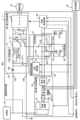
- FIG. 1 is a diagram showing a circuit configuration of a drive control device according to a first embodiment
- FIG. 1 is a block diagram showing a configuration of a conversion control device according to a first embodiment
- FIG. 1 is a block diagram showing a configuration of a first control unit according to a first embodiment
- FIG. 1 is a block diagram showing a hardware configuration of a switching control unit and a conversion control device according to a first embodiment.
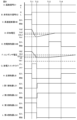
- 1 is a timing chart showing an example of an operation of the drive control device according to the first embodiment when power is supplied from a main power source to a first power conversion device;
- FIG. 1 is a diagram showing a circuit configuration of a drive control device according to a first embodiment
- FIG. 1 is a block diagram showing a configuration of a conversion control device according to a first embodiment
- FIG. 1 is a block diagram showing a configuration of a first control unit according to a
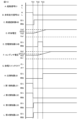
- FIG. 1 is a diagram showing an example of a current flow in the drive control device according to the first embodiment when power is supplied from a main power source to a first power conversion device; 1 is a timing chart showing an example of an operation of the drive control device according to the first embodiment when power supply from a main power source to a first power conversion device is stopped.
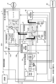
- FIG. 1 is a diagram showing an example of a current flow in the drive control device according to the first embodiment when power supply from a main power source to a first power conversion device is stopped.
- 1 is a timing chart showing an example of an operation of the drive control device according to the first embodiment when power supply from a main power source to a first power conversion device is resumed.
- FIG. 13 is a diagram showing a circuit configuration of a drive control device according to a second embodiment
- FIG. 11 is a block diagram showing a configuration of a first control unit according to a second embodiment
- FIG. 1 is a block diagram showing a modification of the hardware configuration of a switching control unit and a conversion control device according to an embodiment.
- the drive control device 1 shown in Fig. 1 includes a first power conversion device 10 that converts DC power supplied from a main power source 92 into power, for example, three-phase AC power, for supplying the power to a motor 91 that generates propulsive force for the railway vehicle, a low-voltage battery device 20 that is charged with the power supplied from the main power source 92, a power source switching device 30 that forms an electric path between the first power conversion device 10 and the low-voltage battery device 20, and a conversion control device 40 that controls the first power conversion device 10.
- a first power conversion device 10 that converts DC power supplied from a main power source 92 into power, for example, three-phase AC power, for supplying the power to a motor 91 that generates propulsive force for the railway vehicle
- a low-voltage battery device 20 that is charged with the power supplied from the main power source 92
- a power source switching device 30 that forms an electric path between the first power conversion device 10 and the low-voltage battery device 20
- the power source switching device 30 and the conversion control device 40 receive from the driver's cab (not shown) a start signal S1 that instructs the train to start up, and an emergency running signal S2 that instructs the train to run in an emergency using the power stored in the low-voltage storage device 20 when the power supply from the main power source 92 is stopped.
- the start signal S1 is a signal that goes to H (High) level when the railway vehicle starts and goes to L (Low) level when the railway vehicle stops.
- the emergency running signal S2 is a signal that goes to H level when the vehicle is running with the supply of power from the main power source 92 to the first power conversion device 10 stopped and goes to L level when the vehicle is running with the first power conversion device 10 receiving power from the main power source 92.
- the motor 91 is, for example, a three-phase induction motor. In FIG. 1, only one motor 91 is shown to avoid complicating the diagram, but the first power conversion device 10 supplies power to one or more motors 91.
- the power supply switching device 30 has a switching circuit 31 that forms an electrical path between the first power conversion device 10 and the low-voltage storage device 20, and a switching control unit 32 that controls the switching circuit 31 to electrically disconnect the first power conversion device 10 and the low-voltage storage device 20 from each other, or electrically connect the first power conversion device 10 and the low-voltage storage device 20 to each other.
- the switching control unit 32 controls the switching circuit 31 to electrically disconnect the first power conversion device 10 and the low-voltage storage device 20 from each other.
- the switching control unit 32 controls the switching circuit 31 to electrically disconnect the first power conversion device 10 and the low-voltage storage device 20 from each other.
- the switching control unit 32 controls the switching circuit 31 to electrically connect the first power conversion device 10 and the low-voltage storage device 20 to each other.
- the switching control unit 32 controls the switching circuit 31 to electrically connect the first power conversion device 10 and the low-voltage storage device 20 to each other.
- the drive control device 1 can drive the electric motor 91 with power discharged from the low-voltage storage device 20 to run the railway vehicle even when the supply of power from the main power source 92 to the first power conversion device 10 is stopped.
- the drive control device 1 further includes a second power conversion device 50 that converts DC power supplied from a main power source 92 into DC power and AC power and supplies the converted DC power and AC power to a low-voltage storage device 20 and a load device 93, respectively.
- the load device 93 is electronic equipment installed in a railway vehicle, such as lighting equipment and on-board equipment.
- the first power conversion device 10 has a positive input terminal 10a, which is the positive terminal on the side of the main power supply 92, and a negative input terminal 10b, which is the negative terminal on the side of the main power supply 92.
- the positive input terminal 10a is connected to the main power supply 92.
- the negative input terminal 10b is grounded.
- the first power conversion device 10 has a high-speed circuit breaker HB, one end of which is connected to the main power supply 92 via the positive input terminal 10a, an inrush suppression circuit 11 that suppresses inrush current, a reactor L1, one end of which is connected to the output side of the inrush suppression circuit 11, a capacitor C1 that forms an LC filter with the reactor L1 to reduce harmonic components, an inverter 12 that converts the DC power supplied via the capacitor C1 into three-phase AC power to be supplied to the motor 91, and a discharge circuit 13 that is connected in parallel to the capacitor C1.
- the high-speed circuit breaker HB is controlled by the conversion control device 40.
- the inrush suppression circuit 11 is electrically connected to the main power supply 92.
- the inrush suppression circuit 11 is electrically disconnected from the main power supply 92.
- the inrush suppression circuit 11 has a main contactor LB, one end of which is connected to the high-speed circuit breaker HB and the other end of which is connected to the reactor L1, and a charging contactor CHB and a charging resistor CHR, which are connected in parallel to the main contactor LB and connected in series to each other.
- the main contactor LB and the charging contactor CHB are controlled by the conversion control device 40.
- the inverter 12 is electrically connected to the main power supply 92 via the inrush suppression circuit 11 and the high-speed circuit breaker HB, or the inverter 12 is electrically connected to the low-voltage storage device 20 via the inrush suppression circuit 11 and the switching circuit 31.
- the inverter 12 is formed, for example, by a power conversion circuit with variable output voltage and output frequency.
- the inverter 12 has a number of switching elements controlled by a pulse width modulation signal output by the conversion control device 40, and free wheel diodes connected in parallel to each switching element. Through the switching operation of the multiple switching elements, the inverter 12 converts the DC power supplied via the capacitor C1 connected between the primary terminals into three-phase AC power, and supplies the converted three-phase AC power to the electric motor 91 connected to the secondary terminals.
- Each switching element may be an IGBT (Insulated Gate Bipolar Transistor), a GTO (Gate Turn-Off thyristor), a MOSFET (Metal-Oxide-Semiconductor Field-Effect Transistor), etc. If each switching element is an IGBT, the anode of the freewheel diode is connected to the emitter terminal of the switching element, and the cathode of the freewheel diode is connected to the collector terminal of the switching element.
- IGBT Insulated Gate Bipolar Transistor
- GTO Gate Turn-Off thyristor
- MOSFET Metal-Oxide-Semiconductor Field-Effect Transistor
- the reactor L1 and the capacitor C1 together form an LC filter that reduces harmonic components generated by the switching operation of the multiple switching elements of the inverter 12.
- Capacitor C1 is connected between the primary terminals of inverter 12 and is charged with DC power supplied from main power source 92 or low-voltage storage device 20.
- the discharge circuit 13 has a discharge resistor OVR and a discharge switch OVT connected in series to each other.
- the discharge switch OVT is controlled by the conversion control device 40.
- the discharge switch OVT has, for example, an IGBT and a free wheel diode connected in parallel to the IGBT. When the discharge switch OVT is turned on, the capacitor C1 is electrically connected to the discharge resistor OVR and the capacitor C1 is discharged.
- the first power conversion device 10 is provided with a voltage sensor PT1 that measures the value of the voltage applied to the first power conversion device 10 as a voltage acquisition unit that acquires the value of the voltage applied to the first power conversion device 10.
- the first power conversion device 10 is further provided with a voltage sensor PT2 that measures the value of the voltage between the terminals of capacitor C1 as a voltage acquisition unit that acquires the value of the voltage between the terminals of capacitor C1.
- the measured values of the voltage sensors PT1 and PT2 are sent to the conversion control device 40.
- the measured value of the voltage sensor PT2 is sent to the switching control unit 32 of the power source switching device 30.
- the second power conversion device 50 has a D/A (Digital/Analog) conversion circuit 51 having the same circuit configuration as the first power conversion device 10, a transformer TR1 to which the D/A conversion circuit 51 is connected to a primary winding, which transforms the AC power output by the D/A conversion circuit 51 and outputs it from a secondary winding, an AC capacitor ACC1 connected to the secondary winding of the transformer TR1, and a rectifier circuit 52 that rectifies the AC power transformed by the transformer TR1 into DC power.
- D/A (Digital/Analog) conversion circuit 51 having the same circuit configuration as the first power conversion device 10
- a transformer TR1 to which the D/A conversion circuit 51 is connected to a primary winding, which transforms the AC power output by the D/A conversion circuit 51 and outputs it from a secondary winding
- an AC capacitor ACC1 connected to the secondary winding of the transformer TR1
- a rectifier circuit 52 that rectifies the AC power transformed by the transformer TR1 into DC power.
- the D/A conversion circuit 51 has the same configuration as the first power conversion device 10, specifically, a high-speed circuit breaker HB, an inrush suppression circuit 11, a reactor L1, an inverter 12, a capacitor C1, a discharge circuit 13, and voltage sensors PT1 and PT2.
- the inverter 12 in the D/A conversion circuit 51 is a static inverter, and the output voltage and output frequency are maintained constant.
- the transformer TR1 is, for example, a delta-star connected transformer, which transforms the AC power supplied from the D/A conversion circuit 51 connected to the primary winding into a voltage suitable for the load device 93, and outputs the transformed AC power from the secondary winding.
- the AC capacitor ACC1 is connected to the secondary winding of the transformer TR1.
- the AC capacitor ACC1 forms an LC filter together with the coil of the transformer TR1, thereby reducing harmonic components generated by the switching operation of the inverter 12 in the D/A conversion circuit 51.
- the rectifier circuit 52 rectifies the AC power transformed by the transformer TR1 into DC power, and supplies the rectified DC power to the low-voltage storage device 20 and the conversion control device 40.
- the low-voltage storage device 20 discharges at a voltage lower than the voltage applied to the first power conversion device 10 when power is supplied from the main power source 92 to the first power conversion device 10.
- the low-voltage storage device 20 discharges at a voltage in the range of 10% to 20% of the voltage applied to the first power conversion device 10 when power is supplied from the main power source 92 to the first power conversion device 10.
- the low-voltage storage device 20 discharges 100V DC power.
- the low-voltage storage device 20 has a first battery module 21 having a plurality of battery cells connected in series with each other, and a second battery module 22 having a plurality of battery cells connected in series with each other.
- the first battery module 21 and the second battery module 22 are independent of each other.
- the positive battery terminal 21a which is the positive terminal of the first battery module 21, and the negative battery terminal 21b, which is the negative terminal, are electrically connected to the first power conversion device 10 or the second power conversion device 50 and the conversion control device 40 via the switching circuit 31.
- the first battery module 21 is charged with DC power output by the second power conversion device 50.
- the first battery module 21 is electrically connected to the first power conversion device 10 or electrically disconnected from the first power conversion device 10 by the switching control unit 32 controlling the switching circuit 31.
- the low-voltage storage device 20 supplies the power stored in the first battery module 21 to the first power conversion device 10.
- the second battery module 22 is electrically connected to the second power conversion device 50 and the conversion control device 40.
- the positive terminal of the second battery module 22 is connected to the connection point between the positive output terminal of the second power conversion device 50 and the positive power supply terminal of the conversion control device 40.
- the negative terminal of the second battery module 22 is connected to the connection point between the negative output terminal of the second power conversion device 50 and the negative power supply terminal of the conversion control device 40.
- the low-voltage storage device 20 supplies the power stored in the second battery module 22 to the conversion control device 40.
- the second battery module 22 serves as a control power source for the conversion control device 40 when the railway vehicle is started and during emergency running after the start.
- the second battery module 22 is charged with DC power output by the second power conversion device 50.
- the switching circuit 31 is electrically connected to the first power conversion device 10, the first battery module 21 of the low-voltage storage device 20, and the second power conversion device 50.
- the switching circuit 31 forms an electrical path between the first power conversion device 10 and the first battery module 21 of the low-voltage storage device 20, and an electrical path between the second power conversion device 50 and the first battery module 21 of the low-voltage storage device 20.
- the switching circuit 31 has a first contactor LS1 and a second contactor LS2 as at least one power supply contactor electrically connected to the first power conversion device 10 and the low-voltage storage device 20.
- the switching circuit 31 further has a third contactor LS3 and a fourth contactor LS4 as at least one charging contactor electrically connected to the low-voltage storage device 20 and the second power conversion device 50.
- the switching circuit 31 preferably further includes a fuse BTF provided in the electrical path between the first power conversion device 10 and the low-voltage storage device 20.
- a fuse BTF provided in the electrical path between the first power conversion device 10 and the low-voltage storage device 20.
- One end of the first contactor LS1 is connected to the positive input terminal 10a of the first power conversion device 10 via a high-speed circuit breaker HB.
- one end of the first contactor LS1 is connected to a connection point between the other end of the high-speed circuit breaker HB and one end of the main contactor LB and one end of the charging contactor CHB of the inrush suppression circuit 11.
- the other end of the first contactor LS1 is connected to the positive battery terminal 21a of the first battery module 21 via a fuse BTF.
- One end of the second contactor LS2 is connected to the negative input terminal 10b of the first power conversion device 10.
- the other end of the second contactor LS2 is connected to the negative battery terminal 21b of the first battery module 21.
- One end of the third contactor LS3 is connected to the connection point between the positive output terminal, which is the positive output terminal of the second power conversion device 50, and the positive power supply terminal, which is the positive terminal of the conversion control device 40.
- the other end of the third contactor LS3 is connected to the positive battery terminal 21a of the first battery module 21.
- One end of the fourth contactor LS4 is connected to the connection point between the negative output terminal, which is the negative output terminal of the second power conversion device 50, and the negative power supply terminal, which is the negative terminal of the conversion control device 40.
- the other end of the fourth contactor LS4 is connected to the negative battery terminal 21b of the first battery module 21.
- the first power conversion device 10 and the first battery module 21 of the low-voltage storage device 20 are electrically connected, and the first battery module 21 supplies DC power to the first power conversion device 10.
- the first contactor LS1 and the second contactor LS2 are opened and the third contactor LS3 and the fourth contactor LS4 are closed, the first power conversion device 10 and the first battery module 21 of the low-voltage storage device 20 are electrically disconnected, and the second power conversion device 50 and the conversion control device 40 are electrically connected to the first battery module 21 of the low-voltage storage device 20.
- the second power conversion device 50 and the conversion control device 40 are electrically connected to the first battery module 21 of the low-voltage storage device 20.
- the switching control unit 32 controls the first contactor LS1, the second contactor LS2, the third contactor LS3, and the fourth contactor LS4 based on the start signal S1, the emergency running signal S2, and the measurement value of the voltage sensor PT2.
- the switching control unit 32 opens the first contactor LS1 and the second contactor LS2 to electrically disconnect the first power conversion device 10 and the first battery module 21 of the low-voltage storage device 20 from each other. At this time, the switching control unit 32 closes the third contactor LS3 and the fourth contactor LS4 to electrically connect the second power conversion device 50 and the conversion control device 40 to the first battery module 21 of the low-voltage storage device 20 from each other.
- the switching control unit 32 electrically connects the first power conversion device 10 and the first battery module 21 of the low-voltage storage device 20 to each other by closing the first contactor LS1 and the second contactor LS2. At this time, the switching control unit 32 electrically disconnects the second power conversion device 50 and the conversion control device 40 from the first battery module 21 of the low-voltage storage device 20 by opening the third contactor LS3 and the fourth contactor LS4.
- the conversion control device 40 controls the first power conversion device 10 and the second power conversion device 50 based on the start signal S1, the emergency run signal S2, and an operation command signal (not shown).
- the operation command signal is a signal output from a main controller provided in the driver's cab, and indicates the target acceleration of the railway vehicle according to the operation of the main controller.
- the conversion control device 40 has a first control unit 41 that controls the first power conversion device 10, and a second control unit 42 that controls the second power conversion device 50.
- the first control unit 41 closes or opens the high-speed circuit breaker HB, main contactor LB, and charging contactor CHB of the first power conversion device 10, and switches on and off the discharge switch OVT of the first power conversion device 10 and the multiple switching elements of the inverter 12.
- the second control unit 42 closes or opens the high-speed circuit breaker HB, main contactor LB, and charging contactor CHB of the D/A conversion circuit 51 of the second power conversion device 50, and switches on and off the discharge switch OVT of the D/A conversion circuit 51 of the second power conversion device 50 and the multiple switching elements of the inverter 12.
- the first control unit 41 has a circuit breaker control unit 43 that closes or opens the high-speed circuit breaker HB, a contactor control unit 44 that closes or opens the main contactor LB and the charging contactor CHB, a discharge control unit 45 that switches the discharge switch OVT on and off, and a switching control unit 46 that switches the multiple switching elements of the inverter 12 on and off.
- the circuit breaker control unit 43 closes or opens the high-speed circuit breaker HB based on the start signal S1 and the emergency run signal S2.
- the contactor control unit 44 acquires measured values from the voltage sensors PT1 and PT2.
- the contactor control unit 44 closes or opens the main contactor LB and the charging contactor CHB based on the start signal S1, the emergency run signal S2, and the measured values of the voltage sensors PT1 and PT2.
- the discharge control unit 45 obtains a measurement value from the voltage sensor PT2 and a pulse width modulation signal from the switching control unit 46.
- the discharge control unit 45 switches the discharge switch OVT on and off based on the start signal S1, the emergency running signal S2, the measurement value of the voltage sensor PT2, and the pulse width modulation signal.
- the switching control unit 46 acquires the measurement value of the voltage sensor PT2 and the operation command signal sent from the cab.
- the switching control unit 46 generates a pulse width modulated signal for controlling each switching element of the inverter 12 in response to the start signal S1, the emergency running signal S2, the measurement value of the voltage sensor PT2, and the operation command signal.
- the switching control unit 46 switches the switching elements on and off by sending each pulse width modulated signal to the switching elements.
- the control portion of the drive control device 1 having the above configuration in other words, the hardware configuration of the switching control unit 32 and the conversion control device 40, is shown in FIG. 5.
- the switching control unit 32 and the conversion control device 40 each include a processor 81, a memory 82, and an interface 83.
- the processor 81, the memory 82, and the interface 83 are connected to each other via a bus 80.
- the functions of each part of the switching control unit 32 and the conversion control device 40 are realized by software, firmware, or a combination of software and firmware.
- the software and firmware are written as programs and stored in the memory 82.
- the processor 81 reads out and executes the programs stored in the memory 82 to realize the functions of each part described above.
- the memory 82 stores programs for executing the processing of the switching control unit 32 or the processing of each part of the conversion control device 40.
- Memory 82 may include, for example, non-volatile or volatile semiconductor memory such as RAM (Random Access Memory), ROM (Read-Only Memory), flash memory, EPROM (Erasable Programmable Read-Only Memory), EEPROM (Electrically Erasable and Programmable Read-Only Memory), magnetic disks, flexible disks, optical disks, compact disks, mini disks, DVDs (Digital Versatile Discs), etc.
- RAM Random Access Memory
- ROM Read-Only Memory
- flash memory flash memory
- EPROM Erasable Programmable Read-Only Memory
- EEPROM Electrical Erasable and Programmable Read-Only Memory
- magnetic disks flexible disks
- optical disks compact disks
- mini disks mini disks
- DVDs Digital Versatile Discs
- the switching control unit 32 is connected to the first contactor LS1, the second contactor LS2, the third contactor LS3, the fourth contactor LS4, and the voltage sensor PT2 via the interface 83.
- the conversion control device 40 is connected to the high-speed circuit breaker HB, the main contactor LB, the charging contactor CHB, the discharge switch OVT, the inverter 12, and the voltage sensors PT1 and PT2 via the interface 83.
- the interface 83 has an interface module that complies with one or more standards depending on the connection destination.
- Figure 6 shows an example of the operation of the drive control device 1 when power is supplied from the main power supply 92 to the first power conversion device 10 and the second power conversion device 50.
- the timing at which the start signal S1 changes from L level to H level is defined as time T1.
- the emergency running signal S2 is maintained at L level, and emergency running is not performed. While emergency running is not performed, the discharge switch OVT is maintained in the off state, as shown in graph G.
- the railway vehicle Before time T1, the railway vehicle is not started, and the high-speed circuit breaker HB, main contactor LB, charging contactor CHB, first contactor LS1, second contactor LS2, third contactor LS3, and fourth contactor LS4 are open. Therefore, before time T1, the first power conversion device 10, the second power conversion device 50, the electric motor 91, and the load device 93 are not receiving power and are stopped.
- the switching control unit 32 maintains the first contactor LS1 and the second contactor LS2 in an open state and closes the third contactor LS3 and the fourth contactor LS4.
- the first battery module 21 of the low-voltage storage device 20 is electrically connected to the second power conversion device 50 and the conversion control device 40, and is electrically disconnected from the first power conversion device 10.
- the time when the circuit breaker control unit 43 of the first control unit 41 of the conversion control device 40 closes the high-speed circuit breaker HB is set to time T2.
- the high-speed circuit breaker HB is closed, DC power is supplied from the main power source 92 to the first power conversion device 10.
- the applied voltage to the first power conversion device 10 indicated by the measured value of the voltage sensor PT1 starts to rise from the voltage value Va1.
- the voltage value Va1 is a value that can be considered to be 0V.
- the time when the applied voltage to the first power conversion device 10 reaches the normal minimum applied voltage ESL0, which is the lower limit of the applied voltage required to drive the motor 91 when power is supplied from the main power source 92 to the first power conversion device 10, is set to time T3. After time T3, the applied voltage to the first power conversion device 10 is assumed to rise to the voltage value Va2.
- the voltage value Va2 is a value that can be considered to match the overhead line voltage.
- the contactor control unit 44 of the first control unit 41 in the conversion control device 40 closes the charging contactor CHB when the measurement value of the voltage sensor PT1, which indicates the value of the voltage applied to the first power conversion device 10, reaches the normal minimum applied voltage ESL0 at time T3.
- the charging contactor CHB is closed, a current flows from the main power supply 92 through the high-speed circuit breaker HB, the charging contactor CHB, and the charging resistor CHR to the capacitor C1. This prevents an inrush current from flowing to the capacitor C1.
- the switching control unit 46 of the first control unit 41 of the conversion control device 40 After time T4 when the terminal voltage of capacitor C1 indicated by the measurement value of voltage sensor PT2 reaches voltage EFCL0, the switching control unit 46 of the first control unit 41 of the conversion control device 40 generates a pulse width modulation signal for each switching element of the inverter 12 in response to the operation command signal.
- the switching control unit 46 determines a torque command value ⁇ *, which is a target value of the torque of the electric motor 91, based on the target acceleration indicated by the operation command signal and the measured value of the rotation speed of the electric motor 91 acquired from a speed sensor (not shown).
- the switching control unit 46 determines an excitation current command value id* and a torque current command value iq* according to the torque command value ⁇ *.
- the switching control unit 46 performs a conversion from three-phase coordinates to dq rotational coordinates based on the estimated rotor position ⁇ of the motor 91, obtained by integrating the measured value of the rotation speed of the motor 91, and each phase current of the motor 91 acquired from a current sensor (not shown), to determine the excitation current value id and the torque current value iq.
- the switching control unit 46 determines the excitation voltage command value Vd* from the difference between the excitation current value id and the excitation current command value id*, and determines the torque voltage command value Vq* from the difference between the torque current value iq and the torque current command value iq*.
- the switching control unit 46 converts the excitation voltage command value Vd* and the torque voltage command value Vq* from dq rotational coordinates to three-phase coordinates based on the estimated position ⁇ to determine the U-phase voltage command value Vu, the V-phase voltage command value Vv, and the W-phase voltage command value Vw, and generates sine waves of each phase indicating the U-phase voltage command value Vu, the V-phase voltage command value Vv, and the W-phase voltage command value Vw.
- the switching control unit 46 generates a pulse width modulation signal by comparing the triangular wave, which is the carrier wave, with the sine waves of each phase.
- the switching control unit 46 sends the above-mentioned pulse width modulation signal to each switching element of the inverter 12 to control the on/off of each switching element, thereby converting the DC power supplied to the inverter 12 from the main power supply 92 into three-phase AC power, and the three-phase AC power is supplied to the electric motor 91. As a result, the electric motor 91 is driven, generating propulsion force for the railway vehicle.
- the second control unit 42 of the conversion control device 40 performs the same control as the first control unit 41. Specifically, the second control unit 42 closes the high-speed circuit breaker HB of the D/A conversion circuit 51 at time T2, closes the charging contactor CHB at time T3, and closes the main contactor LB at time T4 to open the charging contactor CHB.
- the switching control unit 46 of the second control unit 42 controls the on/off of multiple switching elements of the inverter 12 of the D/A conversion circuit 51, so that the DC power supplied from the main power source 92 to the D/A conversion circuit 51 is converted to AC power and supplied to the load device 93 and the rectifier circuit 52.
- the AC power is rectified to DC power by the rectifier circuit 52, and the DC power is supplied to the low-voltage storage device 20 and the conversion control device 40.
- the first power conversion device 10 converts the DC power supplied from the main power supply 92 into three-phase AC power and supplies the converted three-phase AC power to the main motor 91, which drives the main motor 91 and generates propulsive force for the railway vehicle.
- the second power conversion device 50 converts the DC power supplied from the main power source 92 into AC power and supplies the converted AC power to the load device 93, thereby operating the load device 93.
- the second power conversion device 50 converts the DC power supplied from the main power source 92 into low-voltage DC power and supplies the low-voltage DC power to the low-voltage storage device 20 and the conversion control device 40, thereby charging the first battery module 21 and the second battery module 22 of the low-voltage storage device 20, and the conversion control device 40 operates using the low-voltage DC power supplied from the second power conversion device 50.
- the operation of the drive control device 1 when the railway vehicle travels through a section without electrification facilities, such as a non-electrified section or a section between a storage yard and an electrified section, after time T4 in Fig. 6 will be described with reference to Figs. 8 and 9.
- the time when the emergency running signal S2 becomes H level in response to the operation of a monitor device provided in the driver's cab, for example, is set to time T11.
- the contactor control unit 44 of the first control unit 41 of the conversion control device 40 opens the main contactor LB that is turned on.
- the switching control unit 46 of the first control unit 41 in the conversion control device 40 turns off the multiple switching elements of the inverter 12, stopping the inverter 12. As a result, power conversion by the first power conversion device 10 is stopped.
- the second control unit 42 of the conversion control device 40 performs the same operation as the first control unit 41 described above. Specifically, at time T11, the circuit breaker control unit 43 of the second control unit 42 of the conversion control device 40 opens the high-speed circuit breaker HB of the D/A conversion circuit 51, the contactor control unit 44 of the second control unit 42 opens the main contactor LB of the D/A conversion circuit 51 that is turned on, and the switching control unit 46 of the second control unit 42 turns off the multiple switching elements of the inverter 12 of the D/A conversion circuit 51 to stop the inverter 12. As a result, power conversion by the second power conversion device 50 is stopped.
- the terminal voltage of the capacitor C1 is a voltage value Vb2, which is higher than the maximum terminal voltage V0 in an emergency, which is set lower than the discharge voltage of the low-voltage storage device 20. If the terminal voltage of the capacitor C1 is higher than the maximum terminal voltage V0 in an emergency when the emergency run signal S2 becomes H level, the discharge control unit 45 of the first control unit 41 of the conversion control device 40 turns on the discharge switch OVT after the switching control unit 46 of the first control unit 41 turns off each switching element of the inverter 12, as shown in graph G. As a result, as shown in graph F, at time T11, the terminal voltage of the capacitor C1 starts to decrease from the voltage value Vb2. Thereafter, as shown in graph F, the timing at which the terminal voltage of the capacitor C1 reaches the maximum terminal voltage V0 in an emergency is set to time T12.
- the switching control unit 32 of the power source switching device 30 opens the third contactor LS3 and the fourth contactor LS4, and then closes the first contactor LS1 and the second contactor LS2, as shown in graphs I, J, K, and L.
- the first battery module 21 of the low-voltage storage device 20 is electrically connected to the first power conversion device 10.
- Time T13 is the time when the voltage applied to the first power conversion device 10 reaches the emergency minimum applied voltage ESL1, which is the lower limit of the applied voltage required to drive the motor 91 during emergency running.
- the emergency minimum applied voltage ESL1 is set lower than the normal minimum applied voltage ESL0, which is the lower limit of the applied voltage required to drive the motor 91 when power is supplied to the first power conversion device 10 from the main power source 92.
- This enables the first power conversion device 10 to operate by receiving DC power output from the low-voltage storage device 20, which has a lower voltage than the main power source 92.
- the voltage applied to the first power conversion device 10 rises to a voltage value Va3.
- the voltage value Va3 is a lower value than the voltage value Va2, which corresponds to the overhead line voltage.
- the contactor control unit 44 of the first control unit 41 in the conversion control device 40 closes the charging contactor CHB when the measurement value of the voltage sensor PT1, which indicates the value of the voltage applied to the first power conversion device 10, reaches the emergency minimum applied voltage ESL1 at time T13.
- the charging contactor CHB is closed, a current flows from the low-voltage storage device 20 through the charging contactor CHB and charging resistor CHR to the capacitor C1. This prevents an inrush current from flowing to the capacitor C1.
- Time T14 is the time when the difference between the terminal voltage of capacitor C1 and the voltage applied to the first power conversion device 10 becomes equal to or less than the upper limit of the voltage difference at which capacitor C1 is considered to be fully charged.
- the terminal voltage of capacitor C1 at this time is EFCL1.
- the upper limit of the voltage difference at which capacitor C1 is considered to be fully charged is set to be smaller than the upper limit of the voltage difference at which capacitor C1 is considered to be fully charged when power is supplied from the main power source 92 to the first power conversion device 10.
- the terminal voltage of capacitor C1 is assumed to rise to voltage value Vb3.
- the switching control unit 46 of the first control unit 41 of the conversion control device 40 sends a pulse width modulation signal to each switching element of the inverter 12 in response to the operation command signal to switch each switching element on and off.
- the control of each switching element of the inverter 12 by the switching control unit 46 is the same as the example of FIG. 6.
- the amplitude of the sine wave of each phase indicating the U-phase voltage command value Vu, the V-phase voltage command value Vv, and the W-phase voltage command value Vw when power is supplied from the low-voltage storage device 20 to the first power conversion device 10 is larger than when power is supplied from the main power source 92 to the first power conversion device 10.
- the modulation rate of the pulse width modulation signal when power is supplied from the low-voltage storage device 20 to the first power conversion device 10 is higher than when power is supplied from the main power source 92 to the first power conversion device 10.
- the pulse width of the pulse width modulation signal becomes wider than when power is supplied from the main power source 92 to the first power conversion device 10. This makes it possible to rotate the electric motor 91 at a speed sufficient to generate propulsive force for the railway vehicle, even if the voltage of the DC power supplied to the inverter 12 is low.
- the switching control unit 32 of the power source switching device 30 opens the first contactor LS1 and the second contactor LS2, and then closes the third contactor LS3 and the fourth contactor LS4.
- the first battery module 21 of the low-voltage storage device 20 is electrically connected to the second power conversion device 50 and the conversion control device 40.
- the circuit breaker control unit 43 of the first control unit 41 of the conversion control device 40 closes the high-speed circuit breaker HB.
- the circuit breaker control unit 43 closes the high-speed circuit breaker HB, for example, after the emergency run signal S2 goes low and the time required for opening the first contactor LS1 and the second contactor LS2 and closing the third contactor LS3 and the fourth contactor LS4 has elapsed.
- the voltage applied to the first power conversion device 10 starts to rise from the voltage value Va3.
- the contactor control unit 44 of the first control unit 41 in the conversion control device 40 closes the charging contactor CHB when the measurement value of the voltage sensor PT1, which indicates the value of the voltage applied to the first power conversion device 10, reaches the normal minimum applied voltage ESL0 at time T22.
- the charging contactor CHB is closed, a current flows from the main power supply 92 through the high-speed circuit breaker HB, the charging contactor CHB, and the charging resistor CHR to the capacitor C1. This prevents an inrush current from flowing to the capacitor C1.
- Time T22 is the time when the difference between the terminal voltage of capacitor C1 and the voltage applied to the first power conversion device 10 falls below the upper limit of the voltage difference at which capacitor C1 is considered to be fully charged.
- the terminal voltage of capacitor C1 at this time is EFCL0.
- the terminal voltage of capacitor C1 is assumed to rise to a voltage value Vb2.
- the switching control unit 46 of the first control unit 41 of the conversion control device 40 When the terminal voltage of capacitor C1 rises to voltage value Vb2, the switching control unit 46 of the first control unit 41 of the conversion control device 40 generates a pulse width modulation signal for each switching element of the inverter 12 in response to an operation command.
- the switching control unit 46 sends the above-mentioned pulse width modulation signal to each switching element of the inverter 12 to control the on/off of each switching element, thereby converting the DC power supplied to the inverter 12 from the main power supply 92 into three-phase AC power, and the three-phase AC power is supplied to the electric motor 91. As a result, the electric motor 91 is driven, generating propulsion force for the railway vehicle.
- the second control unit 42 of the conversion control device 40 performs the same control as the first control unit 41. Specifically, when the third contactor LS3 and the fourth contactor LS4 are closed, the second control unit 42 closes the high-speed circuit breaker HB, closes the charging contactor CHB at time T22, and closes the main contactor LB at time T23 to open the charging contactor CHB.
- the first power conversion device 10 converts the DC power supplied from the main power supply 92 into three-phase AC power and supplies the converted three-phase AC power to the main motor 91, which drives the main motor 91 and generates propulsive force for the railway vehicle.
- the power supply switching device 30 provided in the drive control device 1 of the first embodiment, during emergency running, the first power conversion device 10 and the low-voltage storage device 20 are electrically connected, and DC power is supplied from the low-voltage storage device 20 to the first power conversion device 10.
- the DC power supplied from the low-voltage storage device 20 is converted into three-phase AC power and the three-phase AC power is supplied to the electric motor 91, thereby generating propulsion force for the railway vehicle.
- the low-voltage storage device 20 is a low-voltage storage device that serves as a control power source for the conversion control device 40 that controls the first power conversion device 10, it is possible to use a small storage device as the low-voltage storage device 20. Therefore, according to the power supply switching device 30 and the drive control device 1 of the first embodiment, the small low-voltage storage device 20 enables the railway vehicle to run even when the power supply from the main power source 92 is stopped.
- the drive control device 1 may have a function of protecting the inverter 12 when an abnormality occurs in the inverter 12, such as a ground fault, overvoltage, overcurrent, etc.
- a drive control device 1 having a function of protecting the inverter 12 will be described in a second embodiment.
- the first power conversion device 10 included in the drive control device 1 shown in Fig. 11 is provided with a current sensor CT1 that measures the value of a current flowing through the first power conversion device 10 as a current acquisition unit that acquires the value of a current flowing through the first power conversion device 10.
- the current sensor CT1 is provided in an electric path between a negative terminal of the primary terminals of the inverter 12 and the second contactor LS2.
- the first control unit 41 of the conversion control device 40 performs a protective operation for the inverter 12 of the first power conversion device 10
- the second control unit 42 of the conversion control device 40 performs a protective operation for protecting the inverter 12 of the D/A conversion circuit 51 of the second power conversion device 50. Since the configurations of the first control unit 41 and the second control unit 42 are similar, the configuration of the first control unit 41 will be described.
- the first control unit 41 includes a protection determination unit 47 that determines whether protection of the inverter 12 is required.
- the protection determination unit 47 acquires the measurement value of the voltage sensor PT1, the measurement value of the voltage sensor PT2, the measurement value of the current sensor CT1, and the emergency run signal S2.
- the protection determination unit 47 determines whether protection of the inverter 12 is required based on at least one of the measurement value of the voltage sensor PT1, the measurement value of the voltage sensor PT2, and the measurement value of the current sensor CT1.
- the protection determination unit 47 determines that protection is required, it sends a signal instructing protection to the switching control unit 46 and the changeover control unit 32.
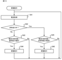
- the protection determination unit 47 acquires a measurement value of the voltage sensor PT1 indicating the value of the voltage applied to the first power conversion device 10 (step S11).
- the protection determination unit 47 determines whether the voltage applied to the first power conversion device 10 acquired in step S11 is less than the normal minimum applied voltage ESL0, which is the lower limit of the applied voltage required to drive the motor 91 when power is supplied from the main power source 92 to the first power conversion device 10 (step S13).
- step S13 If the applied voltage to the first power conversion device 10 obtained in step S11 is less than the normal minimum applied voltage ESL0 (step S13; Yes), the protection determination unit 47 determines that protection of the inverter 12 is necessary, and sends a signal instructing protection to the switching control unit 46 and the changeover control unit 32 (step S14).
- step S14 If the voltage applied to the first power conversion device 10 obtained in step S11 is equal to or higher than the normal minimum applied voltage ESL0 (step S13; No), the process of step S14 is not performed.
- the protection determination unit 47 determines whether the voltage applied to the first power conversion device 10 acquired in step S11 is less than the emergency minimum applied voltage ESL1, which is the lower limit of the applied voltage required to drive the electric motor 91 during emergency running (step S15). As in the first embodiment, the emergency minimum applied voltage ESL1 is set lower than the normal minimum applied voltage ESL0.
- step S15 If the applied voltage to the first power conversion device 10 obtained in step S11 is less than the minimum emergency applied voltage ESL1 (step S15; Yes), the protection determination unit 47 determines that protection of the inverter 12 is necessary and sends a signal instructing protection to the switching control unit 46 and the changeover control unit 32 (step S16).
- step S11 If the voltage applied to the first power conversion device 10 obtained in step S11 is equal to or higher than the minimum emergency voltage ESL1 (step S15; No), the process of step S16 is not performed.
- the protection determination unit 47 repeats the above process while the inverter 12 is operating under the control of the switching control unit 46.
- FIG. 14 Another example of the protection operation of the inverter 12 of the first power conversion device 10 performed by the conversion control device 40 will be described with reference to FIG. 14.
- the protection determination unit 47 starts the processing of the protection operation shown in FIG. 14.
- the protection determination unit 47 acquires the measurement value of the voltage sensor PT2 that measures the terminal voltage of the capacitor C1 (step S21).
- the protection determination unit 47 determines whether the terminal voltage of the capacitor C1 acquired in step S21 is less than the normal minimum terminal voltage, which is the lower limit of the terminal voltage of the capacitor C1 required to drive the motor 91 when power is supplied from the main power source 92 to the first power conversion device 10 (step S23).
- step S23 If the terminal voltage of capacitor C1 obtained in step S21 is less than the normal minimum terminal voltage (step S23; Yes), the protection determination unit 47 determines that protection of the inverter 12 is necessary, and sends a signal instructing protection to the switching control unit 46 and the changeover control unit 32 (step S24).
- step S21 If the terminal voltage of capacitor C1 obtained in step S21 is equal to or higher than the normal minimum terminal voltage (step S23; No), the process of step S24 is not performed.
- the protection determination unit 47 determines whether the terminal voltage of the capacitor C1 acquired in step S21 is less than the minimum terminal voltage in emergency, which is the lower limit of the terminal voltage of the capacitor C1 required to drive the motor 91 during emergency running (step S25).
- the minimum terminal voltage in emergency is set lower than the normal minimum terminal voltage.
- step S25 If the terminal voltage of capacitor C1 obtained in step S21 is less than the minimum terminal voltage in an emergency (step S25; Yes), the protection determination unit 47 determines that protection of the inverter 12 is necessary, and sends a signal instructing protection to the switching control unit 46 and the changeover control unit 32 (step S26).
- step S21 If the terminal voltage of capacitor C1 obtained in step S21 is equal to or greater than the minimum terminal voltage in an emergency (step S25; No), the process of step S26 is not performed.
- the protection determination unit 47 repeats the above process while the inverter 12 is operating under the control of the switching control unit 46.
- FIG. 15 Another example of the protection operation of the inverter 12 of the first power conversion device 10 performed by the conversion control device 40 will be described with reference to FIG. 15.
- the protection determination unit 47 starts the processing of the protection operation shown in FIG. 15.
- the protection determination unit 47 acquires the measurement value of the voltage sensor PT1 indicating the value of the voltage applied to the first power conversion device 10 and the measurement value of the voltage sensor PT2 indicating the value of the voltage between the terminals of the capacitor C1 (step S31). The protection determination unit 47 calculates the absolute value of the voltage difference between the voltage applied to the first power conversion device 10 and the voltage between the terminals of the capacitor C1 (step S32).
- the protection determination unit 47 determines whether the absolute value of the voltage difference calculated in step S32 is greater than the normal maximum voltage difference, which is the upper limit of the absolute value of the voltage difference between the applied voltage and the terminal voltage that can drive the motor 91 when power is supplied from the main power source 92 to the first power conversion device 10 (step S34).
- step S34 If the absolute value of the voltage difference calculated in step S32 is greater than the normal maximum voltage difference (step S34; Yes), the protection determination unit 47 determines that protection of the inverter 12 is necessary, and sends a signal instructing protection to the switching control unit 46 and the changeover control unit 32 (step S35).
- step S34 If the absolute value of the voltage difference calculated in step S32 is equal to or less than the normal maximum voltage difference (step S34; No), the process of step S35 is not performed.
- the protection determination unit 47 determines whether the absolute value of the voltage difference calculated in step S32 is greater than the maximum emergency voltage difference, which is the upper limit of the absolute value of the voltage difference between the applied voltage and the terminal voltage that can drive the electric motor 91 during emergency running (step S36).
- the maximum emergency voltage difference is normally set to be smaller than the minimum voltage difference.
- step S36 If the absolute value of the voltage difference calculated in step S32 is greater than the maximum emergency voltage difference (step S36; Yes), the protection determination unit 47 determines that protection of the inverter 12 is necessary, and sends a signal instructing protection to the switching control unit 46 and the changeover control unit 32 (step S37).
- step S32 If the absolute value of the voltage difference calculated in step S32 is equal to or less than the maximum emergency voltage difference (step S36; No), the process of step S37 is not performed.
- the protection determination unit 47 repeats the above process while the inverter 12 is operating under the control of the switching control unit 46.
- FIG. 16 Another example of the protection operation of the inverter 12 of the first power conversion device 10 performed by the conversion control device 40 will be described with reference to FIG. 16.
- the protection determination unit 47 starts the processing of the protection operation shown in FIG. 16.
- the protection determination unit 47 acquires the measurement value of the current sensor CT1 that measures the value of the current flowing through the first power conversion device 10 (step S41).
- the emergency running signal is at L level, i.e., when emergency running is not in progress (step S42; No)
- the protection determination unit 47 determines whether the measurement value of the current sensor CT1 acquired in step S41 is greater than the normal maximum current, which is the upper limit of the absolute value of the current flowing through the first power conversion device 10 when power is supplied from the main power source 92 to the first power conversion device 10 (step S43).
- step S43 If the absolute value of the current acquired in step S41 is greater than the normal maximum current (step S43; Yes), the protection determination unit 47 determines that protection of the inverter 12 is necessary, and sends a signal instructing protection to the switching control unit 46 and the changeover control unit 32 (step S44).
- step S41 If the absolute value of the current obtained in step S41 is equal to or less than the normal maximum current (step S43; No), the process of step S44 is not performed.
- the protection determination unit 47 determines whether the measured current value acquired in step S41 is greater than the maximum emergency current, which is the upper limit of the current flowing through the first power conversion device 10 during emergency running (step S45).
- the maximum emergency current is normally set to be smaller than the minimum current.
- step S45 If the measured current value obtained in step S41 is greater than the maximum emergency current (step S45; Yes), the protection determination unit 47 determines that protection of the inverter 12 is necessary, and sends a signal instructing protection to the switching control unit 46 and the changeover control unit 32 (step S46).
- step S41 If the measured current value obtained in step S41 is equal to or less than the maximum emergency current (step S45; No), the process of step S46 is not performed.
- the protection determination unit 47 repeats the above process while the inverter 12 is operating under the control of the switching control unit 46.
- the switching control unit 46 which has acquired a signal instructing protection, turns off each switching element of the inverter 12. As a result, the first power conversion device 10 stops.
- the switching control unit 32 electrically disconnects the first power conversion device 10 and the low-voltage storage device 20.
- the switching control unit 32 acquires a signal instructing protection, if the first contactor LS1 and the second contactor LS2 are closed, it opens the first contactor LS1 and the second contactor LS2. This disconnects the first battery module 21 of the low-voltage storage device 20 from the first power conversion device 10, and the occurrence of abnormalities such as overcurrent and overvoltage in the first battery module 21 of the low-voltage storage device 20 when an abnormality occurs in the first power conversion device 10 is suppressed.
- the protection determination unit 47 in the second control unit 42 performs the same processing as the protection determination unit 47 in the first control unit 41. However, since the second power conversion device 50 stops operating during emergency running, the protection determination unit 47 in the second control unit 42 does not perform the operations during emergency running in Figures 13 to 16, specifically, steps S15 and S16 in Figure 13, steps S25 and S26 in Figure 14, steps S36 and S37 in Figure 15, and steps S45 and S46 in Figure 16.
- the switching control unit 32 electrically disconnects the second power conversion device 50 and the low-voltage storage device 20.
- the switching control unit 32 acquires a signal instructing protection, if the third contactor LS3 and the fourth contactor LS4 are closed, it opens the third contactor LS3 and the fourth contactor LS4. This disconnects the first battery module 21 of the low-voltage storage device 20 from the second power conversion device 50, and the occurrence of abnormalities such as overcurrent and overvoltage in the first battery module 21 of the low-voltage storage device 20 when an abnormality occurs in the second power conversion device 50 is suppressed.
- the drive control device 1 performs a protection operation for the inverter 12 of the first power conversion device 10 when power is being supplied from the main power source 92 to the first power conversion device 10 and when power is being supplied from the low-voltage storage device 20 to the first power conversion device 10.
- the drive control device 1 performs a protection operation for the inverter 12 of the D/A conversion circuit 51 of the second power conversion device 50 when power is being supplied from the main power source 92 to the first power conversion device 10 and the second power conversion device 50. This makes it possible to protect the inverter 12 when an abnormality occurs in the inverter 12.
- the present disclosure is not limited to the above-described embodiment.
- the above-described circuit configuration is an example.
- the switching circuit 31 may have only either the first contactor LS1 or the second contactor LS2.
- the switching circuit 31 may have only either the third contactor LS3 or the fourth contactor LS4.
- the circuit configuration of the inrush suppression circuit 11 is not limited to the above example.
- the main contactor LB and the charging contactor CHB may be connected in series, and a charging resistor CHR may be provided in parallel with the charging contactor CHB.
- the contactor control unit 44 closes both the main contactor LB and the charging contactor CHB, and then opens the charging contactor CHB when the capacitor C1 is sufficiently charged.
- the drive control device 1 may be mounted on a railway vehicle that uses an AC power supply system. When mounted on a railway vehicle that uses an AC power supply system, the drive control device 1 may receive a supply of DC power that is collected by a current collector, stepped down by a high-voltage transformer, and converted by a converter. In this case, instead of the high-speed circuit breaker HB provided in the first power conversion device 10, a high-speed circuit breaker may be provided between the primary winding of the high-voltage transformer and the current collector.
- the control of the first power conversion device 10 and the second power conversion device 50 by the first control unit 41 and the second control unit 42 is not limited to the above example.
- the contactor control unit 44 may open the main contactor LB and then the circuit breaker control unit 43 may open the high-speed circuit breaker HB, or the circuit breaker control unit 43 may open the high-speed circuit breaker HB and then the contactor control unit 44 may open the main contactor LB.
- the circuit breaker control unit 43 and the contactor control unit 44 may open the high-speed circuit breaker HB and the main contactor LB at the same timing, respectively.
- a contactor may be provided between the second battery module 22 and the connection point between the second power conversion device 50 and the conversion control device 40, and the contactor may be turned on when the second battery module 22 is used as a power source for the conversion control device 40, such as when starting a railway vehicle.
- the circuit configuration of the switching circuit 31 is not limited to the above example.
- a line breaker, a semiconductor element, etc. may be provided instead of the first contactor LS1, the second contactor LS2, the third contactor LS3, and the fourth contactor LS4.
- the control of the switching circuit 31 by the switching control unit 32 is not limited to the above example.
- the switching control unit 32 may simultaneously close the first contactor LS1 and the second contactor LS2 and open the third contactor LS3 and the fourth contactor LS4.
- the position at which the current sensor CT1 is provided is not limited to the above example.
- the current sensor CT1 is provided at any position where it is possible to measure the value of the current flowing through the first power conversion device 10, both when power is supplied to the first power conversion device 10 from the main power source 92 and when power is supplied to the first power conversion device 10 from the low-voltage storage device 20.
- the current sensor CT1 may be provided between the output side of the inrush suppression circuit 11 and the reactor L1.
- the hardware configuration of the switching control unit 32 and the conversion control device 40 is not limited to the above example.
- a modified example of the hardware configuration of the switching control unit 32 and the conversion control device 40 is shown in FIG. 17.
- the switching control unit 32 and the conversion control device 40 may be realized by a processing circuit 84.
- the switching control unit 32 is connected to the first contactor LS1, the second contactor LS2, the third contactor LS3, the fourth contactor LS4, and the voltage sensor PT2 via an interface circuit 85.
- the conversion control device 40 is connected to the high-speed circuit breaker HB, the main contactor LB, the charging contactor CHB, the discharge switch OVT, the inverter 12, the voltage sensors PT1 and PT2, and the current sensor CT1 via an interface circuit 85.
- the processing circuit 84 When the processing circuit 84 is dedicated hardware, the processing circuit 84 has, for example, a single circuit, a composite circuit, a processor, an ASIC (Application Specific Integrated Circuit), an FPGA (Field Programmable Gate Array), or a combination of these. Each part of the switching control unit 32 and the conversion control device 40 may be realized by an individual processing circuit 84 or may be realized by a common processing circuit 84.
- the switching control unit 32 and the conversion control device 40 may be realized by dedicated hardware, and other parts may be realized by software or firmware.
- the circuit breaker control unit 43 and the contactor control unit 44 may be realized by the processing circuit 84 shown in FIG. 17, and the discharge control unit 45 and the switching control unit 46 may be realized by the processor 81 shown in FIG. 5 reading and executing a program stored in the memory 82.
- At least a part of the switching control unit 32 and the conversion control device 40 may be realized as a function of a train information management system.
- the start signal S1 and the emergency running signal S2 may be supplied to the switching control unit 32 and the conversion control device 40 from the train information management system.
- the drive control device 1 is not limited to being installed in railway vehicles, but may be installed in any moving object that runs on power supplied from an external source, such as a trolley bus.
- 1 Drive control device 10 First power conversion device, 10a Positive input terminal, 10b Negative input terminal, 11 Inrush suppression circuit, 12 Inverter, 13 Discharge circuit, 20 Low voltage storage device, 21 First battery module, 21a Positive battery terminal, 21b Negative battery terminal, 22 Second battery module, 30 Power source switching device, 31 Switching circuit, 32 Switching control unit, 40 Conversion control device, 41 First control unit, 42 Second control unit, 43 Circuit breaker control unit, 44 Contactor control unit, 45 Discharge control unit, 46 Switching control unit, 47 Protection determination unit, 50 Second power conversion device, 51 D/A conversion circuit, 52 Rectifier circuit, 80 bus, 81 processor, 82 memory, 83 interface, 84 processing circuit, 85 interface circuit, 91 motor, 92 main power supply, 93 load device, ACC1 AC capacitor, BTF fuse, C1 capacitor, CHB charging contactor, CHR charging resistor, CT1 current sensor, HB high-speed circuit breaker, LB main contactor, LS1 first contactor, LS2 second contactor, LS3 third contact
Landscapes
- Engineering & Computer Science (AREA)
- Power Engineering (AREA)
- Transportation (AREA)
- Mechanical Engineering (AREA)
- Life Sciences & Earth Sciences (AREA)
- Sustainable Development (AREA)
- Sustainable Energy (AREA)
- Electric Propulsion And Braking For Vehicles (AREA)
- Charge And Discharge Circuits For Batteries Or The Like (AREA)
- Stand-By Power Supply Arrangements (AREA)
- Protection Of Static Devices (AREA)
Priority Applications (4)
| Application Number | Priority Date | Filing Date | Title |
|---|---|---|---|
| EP22967150.8A EP4628348A4 (en) | 2022-11-30 | 2022-11-30 | POWER SUPPLY SWITCHING DEVICE AND DRIVE CONTROL DEVICE |
| JP2023523058A JP7331294B1 (ja) | 2022-11-30 | 2022-11-30 | 電源切替装置および駆動制御装置 |
| PCT/JP2022/044151 WO2024116317A1 (ja) | 2022-11-30 | 2022-11-30 | 電源切替装置および駆動制御装置 |
| JP2023129789A JP2024079558A (ja) | 2022-11-30 | 2023-08-09 | 電源切替装置および駆動制御装置 |
Applications Claiming Priority (1)
| Application Number | Priority Date | Filing Date | Title |
|---|---|---|---|
| PCT/JP2022/044151 WO2024116317A1 (ja) | 2022-11-30 | 2022-11-30 | 電源切替装置および駆動制御装置 |
Publications (1)
| Publication Number | Publication Date |
|---|---|
| WO2024116317A1 true WO2024116317A1 (ja) | 2024-06-06 |
Family
ID=87577157
Family Applications (1)
| Application Number | Title | Priority Date | Filing Date |
|---|---|---|---|
| PCT/JP2022/044151 Ceased WO2024116317A1 (ja) | 2022-11-30 | 2022-11-30 | 電源切替装置および駆動制御装置 |
Country Status (3)
| Country | Link |
|---|---|
| EP (1) | EP4628348A4 (https=) |
| JP (2) | JP7331294B1 (https=) |
| WO (1) | WO2024116317A1 (https=) |
Cited By (1)
| Publication number | Priority date | Publication date | Assignee | Title |
|---|---|---|---|---|
| CN120245754A (zh) * | 2025-06-03 | 2025-07-04 | 浙江吉利控股集团有限公司 | 驱动电源、电机控制器以及车辆 |
Citations (6)
| Publication number | Priority date | Publication date | Assignee | Title |
|---|---|---|---|---|
| JP2011167047A (ja) * | 2010-02-15 | 2011-08-25 | East Japan Railway Co | 電気車の主回路 |
| JP2013225963A (ja) * | 2012-04-20 | 2013-10-31 | Hitachi Ltd | 電気鉄道車両の駆動システム |
| WO2015001621A1 (ja) * | 2013-07-02 | 2015-01-08 | 三菱電機株式会社 | ハイブリッド駆動システム |
| WO2020105080A1 (ja) * | 2018-11-19 | 2020-05-28 | 三菱電機株式会社 | 電力変換装置および断線検出方法 |
| JP2021044978A (ja) | 2019-09-12 | 2021-03-18 | 東海旅客鉄道株式会社 | 電力変換システム |
| WO2021192141A1 (ja) * | 2020-03-26 | 2021-09-30 | 三菱電機株式会社 | 電力変換装置 |
Family Cites Families (4)
| Publication number | Priority date | Publication date | Assignee | Title |
|---|---|---|---|---|
| JPH0698409A (ja) * | 1992-09-11 | 1994-04-08 | Hitachi Ltd | インバータ制御式鉄道電気車両 |
| EP2340957B1 (en) * | 2008-10-23 | 2018-08-29 | Mitsubishi Electric Corporation | Propulsion control device for electric car |
| JP5558022B2 (ja) * | 2009-04-15 | 2014-07-23 | 株式会社東芝 | 電気車の蓄電制御装置及び蓄電制御方法 |
| JP6736370B2 (ja) * | 2016-06-16 | 2020-08-05 | 東海旅客鉄道株式会社 | 電力変換システム |
-
2022
- 2022-11-30 JP JP2023523058A patent/JP7331294B1/ja active Active
- 2022-11-30 WO PCT/JP2022/044151 patent/WO2024116317A1/ja not_active Ceased
- 2022-11-30 EP EP22967150.8A patent/EP4628348A4/en active Pending
-
2023
- 2023-08-09 JP JP2023129789A patent/JP2024079558A/ja active Pending
Patent Citations (6)
| Publication number | Priority date | Publication date | Assignee | Title |
|---|---|---|---|---|
| JP2011167047A (ja) * | 2010-02-15 | 2011-08-25 | East Japan Railway Co | 電気車の主回路 |
| JP2013225963A (ja) * | 2012-04-20 | 2013-10-31 | Hitachi Ltd | 電気鉄道車両の駆動システム |
| WO2015001621A1 (ja) * | 2013-07-02 | 2015-01-08 | 三菱電機株式会社 | ハイブリッド駆動システム |
| WO2020105080A1 (ja) * | 2018-11-19 | 2020-05-28 | 三菱電機株式会社 | 電力変換装置および断線検出方法 |
| JP2021044978A (ja) | 2019-09-12 | 2021-03-18 | 東海旅客鉄道株式会社 | 電力変換システム |
| WO2021192141A1 (ja) * | 2020-03-26 | 2021-09-30 | 三菱電機株式会社 | 電力変換装置 |
Cited By (2)
| Publication number | Priority date | Publication date | Assignee | Title |
|---|---|---|---|---|
| CN120245754A (zh) * | 2025-06-03 | 2025-07-04 | 浙江吉利控股集团有限公司 | 驱动电源、电机控制器以及车辆 |
| CN120245754B (zh) * | 2025-06-03 | 2025-09-09 | 浙江吉利控股集团有限公司 | 驱动电源、电机控制器以及车辆 |
Also Published As
| Publication number | Publication date |
|---|---|
| JP2024079558A (ja) | 2024-06-11 |
| JP7331294B1 (ja) | 2023-08-22 |
| EP4628348A4 (en) | 2026-01-21 |
| JPWO2024116317A1 (https=) | 2024-06-06 |
| EP4628348A1 (en) | 2025-10-08 |
Similar Documents
| Publication | Publication Date | Title |
|---|---|---|
| CN104024029B (zh) | 电动车控制装置以及电动车 | |
| US6486568B1 (en) | Power system using a multi-functional power interface unit | |
| CN111082671B (zh) | 电梯系统中的功率管理 | |
| US9774215B2 (en) | Power conversion apparatus | |
| KR950013353B1 (ko) | 전기 기차용 파워콘버터 장치 | |
| JP2011024369A (ja) | 電力変換装置 | |
| EP4564659A1 (en) | Power conversion device | |
| KR20230013551A (ko) | 모터 구동 시스템을 이용한 차량용 배터리 충전 시스템 | |
| US11097620B2 (en) | Circuit system for railroad vehicle | |
| US20130020972A1 (en) | Load drive apparatus | |
| JP2010098851A (ja) | 電動車両 | |
| JP7331294B1 (ja) | 電源切替装置および駆動制御装置 | |
| CN115520046A (zh) | 利用马达驱动系统的车辆电池充电系统 | |
| KR100213460B1 (ko) | 전기차 제어장치 | |
| JP6289597B1 (ja) | 車両用電源装置および車両用電源装置の制御方法 | |
| JP7201488B2 (ja) | インバータ保護装置 | |
| US20060097690A1 (en) | Charger for an industrial truck | |
| JPWO2019116499A1 (ja) | 鉄道車両用電力変換システム | |
| JP7407079B2 (ja) | 電力変換システム、その制御方法およびそれを搭載した鉄道車両 | |
| JP7595819B2 (ja) | 駆動制御装置 | |
| JP2009219225A (ja) | 車両駆動システム | |
| JP7301686B2 (ja) | 電力変換システム | |
| JP2024120115A (ja) | 電力変換装置および電力変換方法 | |
| JP7651072B2 (ja) | 鉄道車両用の電源装置 | |
| KR102769038B1 (ko) | 고전압 강제 방전 장치 및 방법 |
Legal Events
| Date | Code | Title | Description |
|---|---|---|---|
| WWE | Wipo information: entry into national phase |
Ref document number: 2023523058 Country of ref document: JP |
|
| 121 | Ep: the epo has been informed by wipo that ep was designated in this application |
Ref document number: 22967150 Country of ref document: EP Kind code of ref document: A1 |
|
| WWE | Wipo information: entry into national phase |
Ref document number: 202517044259 Country of ref document: IN |
|
| WWP | Wipo information: published in national office |
Ref document number: 202517044259 Country of ref document: IN |
|
| WWE | Wipo information: entry into national phase |
Ref document number: 2022967150 Country of ref document: EP |
|
| NENP | Non-entry into the national phase |
Ref country code: DE |
|
| ENP | Entry into the national phase |
Ref document number: 2022967150 Country of ref document: EP Effective date: 20250630 |
|
| WWP | Wipo information: published in national office |
Ref document number: 2022967150 Country of ref document: EP |