WO2024079814A1 - コイル部品 - Google Patents
コイル部品 Download PDFInfo
- Publication number
- WO2024079814A1 WO2024079814A1 PCT/JP2022/038052 JP2022038052W WO2024079814A1 WO 2024079814 A1 WO2024079814 A1 WO 2024079814A1 JP 2022038052 W JP2022038052 W JP 2022038052W WO 2024079814 A1 WO2024079814 A1 WO 2024079814A1
- Authority
- WO
- WIPO (PCT)
- Prior art keywords
- coil
- core
- conductor
- hole
- axis direction
- Prior art date
- Legal status (The legal status is an assumption and is not a legal conclusion. Google has not performed a legal analysis and makes no representation as to the accuracy of the status listed.)
- Ceased
Links
Images


Classifications
-
- H—ELECTRICITY
- H01—ELECTRIC ELEMENTS
- H01F—MAGNETS; INDUCTANCES; TRANSFORMERS; SELECTION OF MATERIALS FOR THEIR MAGNETIC PROPERTIES
- H01F17/00—Fixed inductances of the signal type
- H01F17/04—Fixed inductances of the signal type with magnetic core
- H01F17/06—Fixed inductances of the signal type with magnetic core with core substantially closed in itself, e.g. toroid
-
- H—ELECTRICITY
- H01—ELECTRIC ELEMENTS
- H01F—MAGNETS; INDUCTANCES; TRANSFORMERS; SELECTION OF MATERIALS FOR THEIR MAGNETIC PROPERTIES
- H01F37/00—Fixed inductances not covered by group H01F17/00
Definitions
- This disclosure relates to coil components.
- Coil components are known that include a core made of a magnetic material and a coil section made of a conductor and wound around the core.
- a coil component in which a pair of coil sections are wound around an annular core can be used as a common mode noise filter (see, for example, JP 62-7101 A (Patent Document 1)).
- the coil component according to the present disclosure includes a core having a through hole and a coil portion wound around the core through the through hole.
- the coil portion includes a first conductor portion and a second conductor portion connected to the first conductor portion.
- the first conductor portion includes a first portion penetrating from the first side to the second side along a first direction, which is the penetrating direction of the through hole, a second portion connected to the first portion on the second side and extending from the inner periphery side to the outer periphery side of the core, and a third portion connected to the side of the second portion opposite to the side connected to the first portion and extending through the outer periphery side of the core toward the first side.
- the second conductor portion includes a fourth portion penetrating from the second side to the first side along the first direction, a fifth portion connected to the fourth portion on the first side and extending from the inner periphery side to the outer periphery side of the core, and a sixth portion connected to the side of the fifth portion opposite to the side connected to the fourth portion and extending through the outer periphery side of the core toward the second side.
- the third and sixth parts have overlapping portions that overlap each other along the first direction and are connected at the overlapping portions.
- FIG. 1 is a schematic perspective view showing the structure of a coil component according to a first embodiment.
- FIG. 2 is a schematic cross-sectional view taken along line II-II in FIG.
- FIG. 3 is a schematic cross-sectional view taken along line III-III in FIG.
- FIG. 4 is a schematic perspective view showing the structure of a coil component according to the second embodiment.
- FIG. 5 is a schematic cross-sectional view taken along line VV in FIG.
- FIG. 6 is a schematic cross-sectional view taken along line VI-VI in FIG.
- FIG. 7 is a schematic perspective view showing the structure of a coil component according to the third embodiment.
- FIG. 8 is a schematic cross-sectional view taken along line VIII-VIII in FIG.
- FIG. 9 is a schematic cross-sectional view taken along line IX-IX in FIG.
- FIG. 10 is a schematic perspective view showing the structure of a coil component according to the fourth embodiment.
- FIG. 11 is a schematic cross-sectional view taken along line XI-XI in FIG.
- FIG. 12 is a schematic perspective view showing the structure of a coil component according to the fifth embodiment.
- FIG. 13 is a schematic cross-sectional view taken along line XIII-XIII in FIG.
- FIG. 14 is a schematic cross-sectional view taken along line XIV-XIV in FIG.
- the coil component according to the present disclosure can achieve both high impedance and the ability to handle large currents.
- the coil component of the present disclosure includes a core having a through hole and a coil portion wound around the core through the through hole.
- the coil portion includes a first conductor portion and a second conductor portion connected to the first conductor portion.
- the first conductor portion includes a first portion penetrating from the first side to the second side along a first direction that is the penetrating direction of the through hole, a second portion connected to the first portion on the second side and extending from the inner peripheral side of the core to the outer peripheral side, and a third portion connected to the side of the second portion opposite to the side connected to the first portion and extending through the outer peripheral side of the core toward the first side.
- the second conductor portion includes a fourth portion penetrating from the second side to the first side along the first direction, a fifth portion connected to the fourth portion on the first side and extending from the inner peripheral side of the core to the outer peripheral side, and a sixth portion connected to the side of the fifth portion opposite to the side connected to the fourth portion and extending through the outer peripheral side of the core toward the second side.
- the third portion and the sixth portion have an overlapping portion where they overlap with each other along the first direction, and are connected to each other at the overlapping portion.
- a structure is adopted in which a first conductor portion and a second conductor portion, each of which includes a portion that penetrates the through hole of the core, a portion that extends from the inner periphery side of the core to the outer periphery side, and a portion that extends through the outer periphery side of the core, are connected at the overlapping portion of the third portion and the sixth portion.
- the coil component of the present disclosure can achieve both handling of large currents and high impedance.
- the first, second, third, fourth, fifth and sixth parts may each be made of a strip-shaped conductor. This configuration makes it easier to increase the cross-sectional area to accommodate large currents and facilitates processing during manufacturing.
- the thickness of the strip-shaped conductor may be constant. This configuration can reduce the types of materials required to fabricate the first conductor portion and the second conductor portion.
- the first and fourth parts may be spaced apart from each other and arranged so that they overlap at least partially in the thickness direction. This configuration makes it easy to reduce the size of the core in the width direction of the first and fourth parts.
- the coil component may have a pair of coil parts including a first coil part and a second coil part.
- a pair of coil parts By having a pair of coil parts, it is possible to obtain a coil component that can be used as, for example, a common mode noise filter.
- the coil component may include a pair of coil parts including a first coil part and a second coil part.
- the first and fourth parts of the first coil part and the first and fourth parts of the second coil part may be arranged so as to overlap at least partially with a gap between them in the thickness direction.
- a coil component usable as a common mode noise filter can be obtained.
- the coil component may include a pair of coil parts including a first coil part and a second coil part.
- the first and fourth parts of the first coil part and the first and fourth parts of the second coil part may be arranged side by side with a gap between them in the width direction.
- a coil component usable as a common mode noise filter can be obtained.
- the first part, the second part, and the third part may be made of a single conductor.
- the fourth part, the fifth part, and the sixth part may be made of a single conductor. This configuration makes it easier to manufacture the coil component of the present disclosure.
- the core may include a main body made of a magnetic material and a resin case that covers the surface of the main body. This configuration allows the main body of the core to be appropriately protected.
- FIG. 1 is a schematic perspective view showing the structure of a coil component in the first embodiment.
- the case 31 of the core 30 is represented by a broken line, and the internal main body portion 32 is represented by a solid line.
- the penetration direction (first direction ⁇ ) of the through hole 30A of the core 30 is defined as the X-axis direction.
- the Y-axis direction which is a direction perpendicular to the X-axis direction
- the Z-axis direction which is a direction perpendicular to the X-axis direction and the Y-axis direction, are defined.
- FIG. 1 is a schematic perspective view showing the structure of a coil component in the first embodiment.
- the case 31 of the core 30 is represented by a broken line
- the internal main body portion 32 is represented by a solid line.
- the penetration direction (first direction ⁇ ) of the through hole 30A of the core 30 is defined as the X-axis direction.
- the Y-axis direction which is a direction perpendic
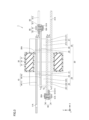
- FIG. 2 is a schematic cross-sectional view taken along the line II-II in FIG. 1.
- FIG. 2 is a cross-sectional view taken along the Y-Z plane.
- FIG. 3 is a schematic cross-sectional view taken along the line III-III in FIG. 1.
- FIG. 3 is a cross-sectional view taken along the X-Z plane.
- the common mode noise filter 1 as the coil component of the first embodiment includes a core 30 and a pair of coil parts, a first coil part 10 and a second coil part 20.
- the core 30 has an annular shape.
- the core 30 has a through hole 30A that penetrates the core 30 in the first direction ⁇ (X-axis direction).
- the core 30 includes a main body part 32 and a case 31.
- the main body part 32 has an annular shape.
- the main body part 32 is made of a magnetic material.
- ferrite, amorphous magnetic material, nanocrystalline magnetic material, permalloy, Sendust registered trademark; an alloy mainly composed of iron and containing silicon and aluminum
- the magnetic material that constitutes the main body part 32 can be used as the magnetic material that constitutes the main body part 32.
- the outer peripheral surface of the main body part 32 has a square shape with four arc-shaped corners in a cross section (Y-Z plane) perpendicular to the first direction ⁇ .
- the wall surface (inner peripheral surface) of the main body 32 surrounding the through hole 30A has a square shape with four arc-shaped corners.
- the case 31 covers the entire main body 32, including the outer peripheral surface, inner peripheral surface, and both end surfaces of the main body 32.
- the case 31 may be composed of two parts that can be separated in the X-axis direction.
- the case 31 is made of resin.
- the first coil portion 10 includes a first conductor portion 14 and a second conductor portion 19.
- the second conductor portion 19 is physically and electrically connected to the first conductor portion 14.
- the first conductor portion 14 includes a first portion 11, a second portion 12, and a third portion 13.
- the first portion 11 penetrates from a first side, which is one side of the core 30, to a second side, which is the other side, along the first direction ⁇ .
- the first portion 11 has a flat plate shape extending linearly along the first direction ⁇ .
- the second portion 12 is connected to the first portion 11 on the second side of the core 30.
- the second portion 12 extends from the inner periphery side to the outer periphery side of the core 30.
- the second portion 12 includes a first region 121, a second region 122, and a third region 123.
- the first region 121 is connected to the first portion 11 and is a portion that extends from the inner periphery side to the outer periphery side of the core 30 along the Y-axis direction.
- the second region 122 is connected to the side of the first region 121 opposite to the side connected to the first portion 11, and is a portion that bends from extending along the Y-axis direction to extending along the Z-axis direction.
- the third region 123 is connected to the side of the second region 122 opposite to the side connected to the first region 121, and is a portion that extends along the Z-axis direction.
- the third portion 13 is connected to the third region 123 located on the side opposite to the side connected to the first portion 11 of the second portion 12.
- the third portion 13 extends along the X-axis direction from the second side of the core 30 to the first side, passing through the outer periphery of the core 30.
- the first part 11, the second part 12, and the third part 13 are composed of an integral conductor.
- the conductors that compose the first part 11, the second part 12, and the third part 13 are not particularly limited, but may be metals with high electrical conductivity, such as copper (pure copper), copper alloys, aluminum, and aluminum alloys.
- the second conductor portion 19 includes a fourth portion 16, a fifth portion 17, and a sixth portion 18.
- the fourth portion 16 penetrates from the second side, which is the other side of the core 30, to the first side, which is one side, along the first direction ⁇ .
- the fourth portion 16 has a flat plate shape extending linearly along the first direction ⁇ .
- the fifth portion 17 is connected to the fourth portion 16 on the first side of the core 30.
- the fifth portion 17 extends from the inner periphery side to the outer periphery side of the core 30.
- the fifth portion 17 includes a first region 171, a second region 172, and a third region 173.
- the first region 171 is connected to the fourth portion 16 and is a portion that extends from the inner periphery side to the outer periphery side of the core 30 along the Y-axis direction.
- the second region 172 is connected to the side opposite to the side connected to the fourth portion 16 of the first region 171, and is a portion that bends from a state where it extends along the Y-axis direction to a state where it extends along the Z-axis direction.
- the third region 173 is connected to the second region 172 on the side opposite to the side connected to the first region 171, and extends along the Z-axis direction.
- the sixth portion 18 is connected to the third region 173 located on the side opposite to the side connected to the fourth portion 16 of the fifth portion 17. The sixth portion 18 extends along the X-axis direction, passing through the outer periphery of the core 30 from the first side to the second side of the core 30.
- the fourth part 16, the fifth part 17, and the sixth part 18 are composed of a single conductor.
- the conductors that compose the fourth part 16, the fifth part 17, and the sixth part 18 are not particularly limited, but may be metals with high electrical conductivity, such as copper (pure copper), copper alloys, aluminum, and aluminum alloys.
- the third portion 13 has an overlapping portion 13B that overlaps with the sixth portion 18 in the thickness direction (Y axis direction) along the first direction (X axis direction).
- the sixth portion 18 has an overlapping portion 18B that overlaps with the third portion 13 in the thickness direction (Y axis direction) along the first direction (X axis direction).
- the third portion 13 and the sixth portion 18 are connected by a fixing member 90 at the overlapping portions 13B, 18B. More specifically, referring to FIG. 2, the third portion 13 has a through hole 13A that penetrates the overlapping portion 13B in the thickness direction (Y axis direction).
- the sixth portion 18 has a through hole 18A that penetrates the overlapping portion 18B in the thickness direction (Y axis direction).
- the through hole 13A and the through hole 18A are arranged so as to overlap in the Y axis direction.
- the fixing member 90 includes a bolt 91 and a nut 92.
- the bolt 91 penetrates the through hole 13A and the through hole 18A and is screwed into the nut 92.
- the overlapping portion 13B and the overlapping portion 18B are physically and electrically connected while being pressed against each other in the thickness direction.
- the second coil portion 20 includes a first conductor portion 24 and a second conductor portion 29.
- the second conductor portion 29 is physically and electrically connected to the first conductor portion 24.
- the first conductor portion 24 includes a first portion 21, a second portion 22, and a third portion 23.
- the first portion 21 penetrates from the second side, which is the other side of the core 30, to the first side, which is one side, along the first direction ⁇ .
- the first portion 21 has a flat plate shape extending linearly along the first direction ⁇ .
- the second portion 22 is connected to the first portion 21 on the first side of the core 30.
- the second portion 22 extends from the inner periphery side to the outer periphery side of the core 30.
- the second portion 22 includes a first region 221, a second region 222, and a third region 223.
- the first region 221 is connected to the first portion 21 and is a portion that extends from the inner periphery side to the outer periphery side of the core 30 along the Y-axis direction.
- the second region 222 is connected to the side of the first region 221 opposite to the side connected to the first portion 21, and is a portion that bends from extending along the Y-axis direction to extending along the Z-axis direction.
- the third region 223 is connected to the side of the second region 222 opposite to the side connected to the first region 221, and is a portion that extends along the Z-axis direction.
- the third portion 23 is connected to the third region 223 located on the side opposite to the side connected to the first portion 21 of the second portion 22.
- the third portion 23 extends along the X-axis direction from the first side of the core 30 to the second side, passing through the outer periphery of the core 30.
- the first part 21, the second part 22, and the third part 23 are composed of a single conductor.
- the conductor that composes the first part 21, the second part 22, and the third part 23 is not particularly limited, but may be a metal with high conductivity, such as copper (pure copper), a copper alloy, aluminum, or an aluminum alloy.
- the second conductor portion 29 includes a fourth portion 26, a fifth portion 27, and a sixth portion 28.
- the fourth portion 26 penetrates from the first side, which is one side of the core 30, to the second side, which is the other side, along the first direction ⁇ .
- the fourth portion 26 has a flat plate shape extending linearly along the first direction ⁇ .
- the fifth portion 27 is connected to the fourth portion 26 on the second side of the core 30.
- the fifth portion 27 extends from the inner periphery side to the outer periphery side of the core 30.
- the fifth portion 27 includes a first region 271, a second region 272, and a third region 273.
- the first region 271 is connected to the fourth portion 26 and is a portion that extends from the inner periphery side to the outer periphery side of the core 30 along the Y-axis direction.
- the second region 272 is connected to the side opposite to the side connected to the fourth portion 26 of the first region 271, and is a portion that bends from a state where it extends along the Y-axis direction to a state where it extends along the Z-axis direction.
- the third region 273 is connected to the second region 272 on the side opposite to the side connected to the first region 271, and extends along the Z-axis direction.
- the sixth portion 28 is connected to the third region 273 located on the side opposite to the side connected to the fourth portion 26 of the fifth portion 27. The sixth portion 28 extends along the X-axis direction, passing through the outer periphery of the core 30 from the second side to the first side of the core 30.
- the fourth part 26, the fifth part 27, and the sixth part 28 are composed of a single conductor.
- the conductors that compose the fourth part 26, the fifth part 27, and the sixth part 28 are not particularly limited, but may be metals with high electrical conductivity, such as copper (pure copper), copper alloys, aluminum, and aluminum alloys.
- the third part 23 has an overlapping part 23B that overlaps with the sixth part 28 in the thickness direction (Y axis direction) along the first direction (X axis direction).
- the sixth part 28 has an overlapping part 28B that overlaps with the third part 23 in the thickness direction (Y axis direction) along the first direction (X axis direction).
- the third part 23 and the sixth part 28 are connected by a fixing member 90 at the overlapping parts 23B, 28B. More specifically, referring to FIG. 2, the third part 23 has a through hole 23A that penetrates the overlapping part 23B in the thickness direction (Y axis direction).
- the sixth part 28 has a through hole 28A that penetrates the overlapping part 28B in the thickness direction (Y axis direction).
- the through hole 23A and the through hole 28A are arranged so as to overlap in the Y axis direction.
- the fixing member 90 includes a bolt 91 and a nut 92.
- the bolt 91 penetrates the through hole 23A and the through hole 28A and is screwed into the nut 92.
- the overlapping portion 23B and the overlapping portion 28B are physically and electrically connected while being pressed against each other in the thickness direction.
- the second coil section 20 has a structure similar to that of the first coil section 10, rotated 180 degrees around the X-axis.
- the second coil section 20 is composed of the same components as the first coil section 10. As a result, the number of types of components that need to be prepared in manufacturing the common mode noise filter 1 is reduced.
- the common mode noise filter 1 further includes a first connecting member 51 and a second connecting member 61 made of a conductor.
- the first connecting member 51 is connected to the fourth portion 26 by a fixing member 90 including a bolt 91 and a nut 92.
- the first connecting member 51 includes a first portion 511 connected to the fourth portion 26 and extending away from the first portion 11 along the Y-axis direction, and a second portion 512 connected to the first portion 511 and extending away from the core 30 along the X-axis direction.
- the fourth portion 26 and the first portion 511 are formed with through holes 26A and 51A that penetrate them in the thickness direction (Z-axis direction), respectively, so as to overlap in the Z-axis direction.
- the bolt 91 penetrates the through hole 51A and the through hole 26A and is screwed into the nut 92.
- the bolt 91 and the nut 92 are fastened together, so that the fourth portion 26 and the first portion 511 are physically and electrically connected to each other in the thickness direction while being pressed against each other.
- the second connecting member 61 is connected to the fourth portion 16 by a fixing member 90 including a bolt 91 and a nut 92.
- the second connecting member 61 includes a first portion 611 connected to the fourth portion 16 and extending away from the first portion 21 along the Y-axis direction, and a second portion 612 connected to the first portion 611 and extending away from the core 30 along the X-axis direction.
- the fourth portion 16 and the first portion 611 are formed with through holes 16A and 61A that penetrate the fourth portion 16 and the first portion 611, respectively, in a thickness direction (Z-axis direction) so as to overlap in the Z-axis direction.
- the bolt 91 penetrates the through hole 61A and the through hole 16A and is screwed into the nut 92.
- the bolt 91 and the nut 92 are fastened together, so that the fourth portion 16 and the first portion 611 are physically and electrically connected to each other while being pressed against each other in the thickness direction.
- the first portion 11 has a through hole 11A formed therethrough in the thickness direction.
- the second portion 512 of the first connection member 51 has a through hole 51B formed therethrough in the thickness direction.
- the end region of the first portion 11 including the region where the through hole 11A of the first portion 11 is formed, and the end region of the first connection member 51 including the region where the through hole 51B of the first connection member 51 is formed can be connected to, for example, a conductive member on the input/output side.
- the through hole 11A and the through hole 51B can be used for fixing by a fixing member having the same structure as the fixing member 90 including the bolt 91 and the nut 92.
- the distance in the Y-axis direction between the end region of the first portion 11 functioning as a terminal and the end region of the first connection member 51 becomes large.
- the first portion 11 and the first connection member 51 can be easily connected to the conductive member on the input/output side by fastening in the Z-axis direction using a bolt and a nut passing through the through hole 11A and the through hole 51B, respectively.
- the second portion 512 of the first connection member 51 may be omitted, and a through hole 51B may be formed in the first portion 511.
- the first portion 21 has a through hole 21A that penetrates the first portion 21 in the thickness direction.
- the second portion 612 of the second connection member 61 has a through hole 61B that penetrates the second portion 612 in the thickness direction.
- the end region of the first portion 21 including the region where the through hole 21A of the first portion 21 is formed, and the end region of the second connection member 61 including the region where the through hole 61B of the second connection member 61 is formed can be connected to a conductive member on the circuit side, for example.
- the through hole 21A and the through hole 61B can be used for fixing by a fixing member similar to the fixing member 90 including the bolt 91 and the nut 92.
- the first portions 11, 21, the second portions 12, 22, the third portions 13, 23, the fourth portions 16, 26, the fifth portions 17, 27, and the sixth portions 18, 28 are each composed of a strip-shaped conductor.
- it is easy to increase the cross-sectional area and handle a large current.
- it is easy to perform processes such as bending to form the second regions 122, 222, 172, 272, and cutting to form the through holes 11A, 26A, 21A, 16A, 13A, 18A, 23A, 28A.
- the thickness of the strip-shaped conductor is constant. This makes it possible to manufacture the first portions 11, 21, the second portions 12, 22, the third portions 13, 23, the fourth portions 16, 26, the fifth portions 17, 27, and the sixth portions 18, 28 from metal plates, such as copper plates, having the same thickness. As a result, the number of types of materials that need to be prepared when manufacturing the common mode noise filter 1 can be reduced.
- the first portion 11 and the fourth portion 16 are arranged to overlap each other in the Z-axis direction with a gap G1 therebetween.
- the first portion 11 and the fourth portion 16 are arranged with a constant gap G1 therebetween. That is, the first portion 11 and the fourth portion 16 are arranged parallel to each other.
- the gap G1 between the first portion 11 and the fourth portion 16 is larger than the thickness t11 of the first portion 11 and the thickness t16 of the fourth portion 16.
- the first portion 21 and the fourth portion 26 are disposed so as to overlap each other in the Z-axis direction with a gap G3 therebetween.
- the first portion 21 and the fourth portion 26 are disposed with a constant gap G3 therebetween. That is, the first portion 21 and the fourth portion 26 are disposed in parallel to each other.
- the gap G3 between the first portion 21 and the fourth portion 26 is larger than the thickness t21 of the first portion 21 and the thickness t26 of the fourth portion 26.
- the first portion 11 and the fourth portion 16 of the first coil portion 10 and the first portion 21 and the fourth portion 26 of the second coil portion 20 are arranged to overlap each other in the Z-axis direction with a gap G2 therebetween.
- the first portion 11 and the fourth portion 16 of the first coil portion 10 and the first portion 21 and the fourth portion 26 of the second coil portion 20 are arranged with a constant gap G2 therebetween. That is, the first portion 11 and the fourth portion 16 of the first coil portion 10 and the first portion 21 and the fourth portion 26 of the second coil portion 20 are arranged in parallel with each other.
- the gap G2 is larger than the gap G1 and the gap G3 .
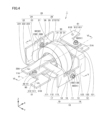
- FIG. 4 is a schematic perspective view showing the structure of a coil component in the second embodiment.
- FIG. 5 is a schematic cross-sectional view taken along line V-V in FIG. 4.
- FIG. 6 is a schematic cross-sectional view taken along line VI-VI in FIG. 4.
- FIGS. 4, 5, and 6 correspond to FIGS. 1, 2, and 3 of the first embodiment, respectively.
- the common mode noise filter 1 of the present embodiment basically has the same structure as the common mode noise filter 1 of the first embodiment described based on FIGS. 1 to 3, and achieves the same effects.
- the common mode noise filter 1 of the second embodiment differs from that of the first embodiment in the shape of the core 30.
- the differences from the first embodiment will be mainly described.
- the core 30 in embodiment 2 has a hollow cylindrical shape.
- the outer peripheral surface of the main body 32 has a circular shape in a cross section perpendicular to the first direction ⁇ (Y-Z plane).
- the wall surface (inner peripheral surface) of the main body 32 surrounding the through hole 30A has a circular shape.
- the case 31 covers the entire main body 32, including the outer peripheral surface, inner peripheral surface, and both end surfaces of the main body 32.
- the common mode noise filter 1 of this embodiment which employs a core 30 having a hollow cylindrical shape, can provide a common mode noise filter that has the same effects as the first embodiment.
- a hollow cylindrical core 30 By employing a hollow cylindrical core 30, it becomes easy to manufacture a core 30 with high magnetic permeability. As a result, it becomes easy to obtain a high-performance common mode noise filter 1.
- FIG. 7 is a schematic perspective view showing the structure of a coil component in the third embodiment.
- FIG. 8 is a schematic cross-sectional view taken along line VIII-VIII in FIG. 7.
- FIG. 9 is a schematic cross-sectional view taken along line IX-IX in FIG. 7.
- FIG. 7, FIG. 8, and FIG. 8 are views corresponding to FIG. 1, FIG. 2, and FIG. 3 of the first embodiment, respectively.
- the common mode noise filter 1 of the present embodiment basically has the same structure as the common mode noise filter 1 of the first embodiment described based on FIG. 1 to FIG. 3, and achieves the same effects.
- the common mode noise filter 1 of the third embodiment is different from the first embodiment in the shape of the core 30 and the positional relationship between the first coil portion 10 and the second coil portion 20.
- the parts different from the first embodiment will be mainly described.
- the core 30 in embodiment 3 has a shape that is wider in the Y-axis direction than in the Z-axis direction.
- the outer peripheral surface of the main body 32 has four arc-shaped corners in a cross section (Y-Z plane) perpendicular to the first direction ⁇ , and has a rectangular shape with its long sides in the Y-axis direction and its short sides in the Z-axis direction.
- the wall surface (inner peripheral surface) of the main body 32 surrounding the through hole 30A has four arc-shaped corners and has a rectangular shape with its long sides in the Y-axis direction and its short sides in the Z-axis direction.
- the first portion 11 and the fourth portion 16 of the first coil portion 10 and the first portion 21 and the fourth portion 26 of the second coil portion 20 are arranged side by side with a gap G2 between them in the width direction (Y-axis direction).
- the first portion 11 and the fourth portion 16 of the first coil portion 10 and the first portion 21 and the fourth portion 26 of the second coil portion 20 are arranged with a constant gap G2 between them. That is, the first portion 11 and the fourth portion 16 of the first coil portion 10 and the first portion 21 and the fourth portion 26 of the second coil portion 20 are arranged in parallel with each other.
- the gap G2 is larger than the gap G1 and the gap G3 .
- FIG. 10 is a schematic perspective view showing the structure of a coil component in the fourth embodiment.
- FIG. 11 is a schematic cross-sectional view taken along line XI-XI in FIG. 10.
- FIGS. 10 and 11 correspond to FIGS. 7 and 9 of the third embodiment, respectively.
- the common mode noise filter 1 of the present embodiment basically has the same structure as the common mode noise filter 1 of the third embodiment described based on FIGS. 7 to 9, and achieves the same effects.
- the common mode noise filter 1 of the fourth embodiment differs from the third embodiment in that it includes a plurality of cores.
- the differences from the third embodiment will be mainly described.
- the common mode noise filter 1 in the fourth embodiment includes a core 40 as a second core in addition to the core 30 as a first core.
- the common mode noise filter 1 in the fourth embodiment includes two cores 30, 40.
- the cores 30 and 40 are arranged side by side in the first direction ⁇ (X-axis direction).
- the cores 30 and 40 have the same shape and are made of the same material, but the common mode noise filter of the present disclosure is not limited to this.
- the cores 30 and 40 may have different shapes (for example, different sizes).
- the cores 30 and 40 may be made of different materials.
- the core 40 has an annular shape, similar to the core 30.
- the core 40 has a through hole 40A that penetrates the core 40 in the first direction ⁇ (X-axis direction).
- the core 40 includes a main body 42 and a case 41.
- the main body 42 has an annular shape.
- the main body 42 is made of a magnetic material, similar to the main body 32.
- the case 41 covers the entire main body 42, including the outer peripheral surface, inner peripheral surface, and both end surfaces of the main body 42.
- the case 41 may be made of two parts that can be separated in the X-axis direction.
- the case 41 is made of resin.
- the first portion 11 of the first conductor 14 penetrates from the first side, which is one side of the core 40, to the second side, which is the other side, along the first direction ⁇ .
- the second portion 12 is connected to the first portion 11 on the second side of the core 40.
- the second portion 12 extends from the inner peripheral side to the outer peripheral side of the core 40 in the Y-axis direction.
- the first region 121 of the second portion 12 extends from the inner peripheral side to the outer peripheral side of the core 40 along the Y-axis direction.
- the third portion 13 extends from the second side of the core 40 to the first side, passing through the outer peripheral side of the core 40 along the X-axis direction.
- the fourth portion 16 of the second conductor 19 penetrates from the second side, which is the other side of the core 40, to the first side, which is one side, along the first direction ⁇ .
- the first portion 21 of the first conductor 24 penetrates from the second side, which is the other side of the core 40, to the first side, which is one side, along the first direction ⁇ .
- the fourth portion 26 of the second conductor 29 penetrates from the first side, which is the one side of the core 40, to the second side, which is the other side, along the first direction ⁇ .
- the fifth portion 27 is connected to the fourth portion 26 on the second side of the core 40.
- the fifth portion 27 extends from the inner periphery side to the outer periphery side of the core 40.
- the first region 271 of the fifth portion 27 is connected to the fourth portion 26 and extends from the inner periphery side to the outer periphery side of the core 40 along the Y-axis direction.
- the sixth portion 28 extends from the second side of the core 40 to the first side, passing through the outer periphery side of the core 40 along the X-axis direction.
- the common mode noise filter 1 of this embodiment includes multiple (specifically, two) cores 30, 40, which makes it easy to improve the magnetic characteristics.
- the common mode noise filter 1 of this embodiment includes multiple (specifically, two) cores 30, 40, which makes it easy to obtain magnetic characteristics that are difficult to achieve when there is only one core. For example, when cores 30, 40 having the same shape and made of the same material are used, the impedance can be approximately doubled compared to when only one core 30 is used.
- FIG. 12 is a schematic perspective view showing the structure of a coil component in the fifth embodiment.
- FIG. 13 is a schematic cross-sectional view taken along line XIII-XIII in FIG. 12.
- FIG. 14 is a schematic cross-sectional view taken along line XVI-XVI in FIG. 12.
- FIGS. 12, 13, and 14 correspond to FIGS. 7, 8, and 9 of the third embodiment, respectively.
- the common mode noise filter 1 of the present embodiment basically has the same structure as the common mode noise filter 1 of the third embodiment described based on FIGS. 7 to 9, and achieves the same effects.
- the common mode noise filter 1 of the fifth embodiment is different from the third embodiment in that the first coil portion 10 and the second coil portion 20 have an insulating layer 71.
- the differences from the third embodiment will be mainly described.
- a portion of the first coil portion 10 and the second coil portion 20 of the common mode noise filter 1 in the fifth embodiment is covered with an insulating layer 71.
- the material constituting the insulating layer 71 is, for example, a resin.
- the first coil portion 10 and the second coil portion 20 may be covered with the insulating layer 71 over the entire area, but in the present embodiment, at least the portions of the first coil portion 10 and the second coil portion 20 facing the inner surface and the end surface of the core 30 are covered with the insulating layer 71, while the periphery of the connection portion with the bolt and nut is not covered with the insulating layer 71.
- the first portion 11 and the fourth portion 26 may be covered with an integral resin.
- the fourth portion 16 and the first portion 21 may be covered with an integral resin.
- the common mode noise filter 1 of this embodiment at least a portion of the first coil portion 10 and the second coil portion 20 is covered with an insulating layer 71, which improves the dielectric strength voltage between the coil portions 10, 20 and the core 30, and the dielectric strength between the portions that make up the coil portions 10, 20.
- the third and sixth parts are connected at the overlapping portion by a fixing member 90 including a bolt 91 and a nut 92.
- the connection method for the coil component of the present disclosure is not limited to this.
- the third and sixth parts may be connected by other methods, such as crimping, welding, or soldering.
- first conductor portion and the second conductor portion are described as being configured from a strip-shaped conductor (strip-shaped bus bar).
- first conductor portion and the second conductor portion in the coil component of the present disclosure are not limited to this configuration.
- the first conductor portion and the second conductor portion may be any conductor that can handle a large current, and may be, for example, a round wire, which has a circular cross section perpendicular to the longitudinal direction, a rectangular wire, or a wire bundle such as a twisted wire.
- the core and the core body have been described as having an annular shape, i.e., a shape that is continuous in the circumferential direction, but the shape of the core and the core body is not limited to this.
- the core and the core body may have, for example, a shape in which a portion of the annular shape has been removed in the circumferential direction, i.e., a shape in which a notch is formed connecting the annular through hole and the outer circumferential surface (a C-shape when viewed in the first direction).
- 1 common mode noise filter 10 first coil part, 11 first part, 11A through hole, 12 second part, 13 third part, 13A through hole, 13B overlapping part, 14 first conductor part, 16 fourth part, 16A through hole, 17 fifth part, 18 sixth part, 18A through hole, 18B overlapping part, 19 second conductor part, 20 second coil part, 21 first part, 21A through hole, 22 second part, 23 third part, 23A through hole, 23B overlapping part, 24 first conductor part, 26 fourth part, 26A through hole, 27 fifth part, 28 sixth part, 28A through hole, 28B overlapping part, 29 second conductor part, 30 core, 30A Through hole, 31 case, 32 main body, 40 core, 40A through hole, 41 case, 42 main body, 51 first connection member, 51A through hole, 51B through hole, 61 second connection member, 61A through hole, 61B through hole, 71 insulating layer, 90 fixing member, 91 bolt, 92 nut, 121 first region, 122 second region, 123 third region, 171 first region,
Landscapes
- Engineering & Computer Science (AREA)
- Power Engineering (AREA)
- Microelectronics & Electronic Packaging (AREA)
- Coils Or Transformers For Communication (AREA)
- Coils Of Transformers For General Uses (AREA)
Priority Applications (2)
| Application Number | Priority Date | Filing Date | Title |
|---|---|---|---|
| PCT/JP2022/038052 WO2024079814A1 (ja) | 2022-10-12 | 2022-10-12 | コイル部品 |
| JP2024550967A JP7786609B2 (ja) | 2022-10-12 | 2022-10-12 | コイル部品 |
Applications Claiming Priority (1)
| Application Number | Priority Date | Filing Date | Title |
|---|---|---|---|
| PCT/JP2022/038052 WO2024079814A1 (ja) | 2022-10-12 | 2022-10-12 | コイル部品 |
Publications (1)
| Publication Number | Publication Date |
|---|---|
| WO2024079814A1 true WO2024079814A1 (ja) | 2024-04-18 |
Family
ID=90669009
Family Applications (1)
| Application Number | Title | Priority Date | Filing Date |
|---|---|---|---|
| PCT/JP2022/038052 Ceased WO2024079814A1 (ja) | 2022-10-12 | 2022-10-12 | コイル部品 |
Country Status (2)
| Country | Link |
|---|---|
| JP (1) | JP7786609B2 (https=) |
| WO (1) | WO2024079814A1 (https=) |
Citations (3)
| Publication number | Priority date | Publication date | Assignee | Title |
|---|---|---|---|---|
| JPH10106861A (ja) * | 1996-09-30 | 1998-04-24 | Soshin Denki Kk | ノイズフィルタ |
| JP2012160522A (ja) * | 2011-01-31 | 2012-08-23 | Fdk Corp | 大電流用コイル部品 |
| JP2019169499A (ja) * | 2018-03-22 | 2019-10-03 | 日立金属株式会社 | コモンモードチョーク |
Family Cites Families (1)
| Publication number | Priority date | Publication date | Assignee | Title |
|---|---|---|---|---|
| JP6894784B2 (ja) * | 2017-07-07 | 2021-06-30 | 矢崎総業株式会社 | サージ電圧低減部材 |
-
2022
- 2022-10-12 WO PCT/JP2022/038052 patent/WO2024079814A1/ja not_active Ceased
- 2022-10-12 JP JP2024550967A patent/JP7786609B2/ja active Active
Patent Citations (3)
| Publication number | Priority date | Publication date | Assignee | Title |
|---|---|---|---|---|
| JPH10106861A (ja) * | 1996-09-30 | 1998-04-24 | Soshin Denki Kk | ノイズフィルタ |
| JP2012160522A (ja) * | 2011-01-31 | 2012-08-23 | Fdk Corp | 大電流用コイル部品 |
| JP2019169499A (ja) * | 2018-03-22 | 2019-10-03 | 日立金属株式会社 | コモンモードチョーク |
Also Published As
| Publication number | Publication date |
|---|---|
| JPWO2024079814A1 (https=) | 2024-04-18 |
| JP7786609B2 (ja) | 2025-12-16 |
Similar Documents
| Publication | Publication Date | Title |
|---|---|---|
| JP4878002B2 (ja) | 電磁機器 | |
| TWI379323B (https=) | ||
| JP6509929B2 (ja) | 導電体ユニット | |
| CN110619994B (zh) | 线圈部件 | |
| CN110619995B (zh) | 线圈部件 | |
| JP6762338B2 (ja) | 端子の圧着方法及び圧着構造 | |
| US11908608B2 (en) | Coil component | |
| CN117766355A (zh) | 熔断器和形成熔断器的方法 | |
| CN115691959A (zh) | 线圈部件 | |
| JP7786609B2 (ja) | コイル部品 | |
| JP4905807B2 (ja) | コイル部品 | |
| JP2020027822A (ja) | ドラム状コア及び巻線型コイル部品 | |
| CN109887723B (zh) | 平衡-不平衡变压器及其制造方法 | |
| US9419485B2 (en) | Coil wire for rotating electrical machine and coil body | |
| US12087488B2 (en) | Coil component and electronic component | |
| JP7151268B2 (ja) | コイル部品 | |
| CN109215976B (zh) | 浪涌电压降低部件 | |
| JP7806962B2 (ja) | コアユニット | |
| JP5088829B2 (ja) | 導体貫通型チョークコイル | |
| EP3929596A1 (en) | Three-phase current detection device | |
| JP2022038324A (ja) | インダクタ部品 | |
| JP2022038327A (ja) | インダクタ部品 | |
| US20240170861A1 (en) | Terminal-equipped electric wire and method of manufacturing terminal-equipped electric wire | |
| CN114334396B (zh) | 线圈部件 | |
| US20240258002A1 (en) | Core and coil component |
Legal Events
| Date | Code | Title | Description |
|---|---|---|---|
| 121 | Ep: the epo has been informed by wipo that ep was designated in this application |
Ref document number: 22962034 Country of ref document: EP Kind code of ref document: A1 |
|
| WWE | Wipo information: entry into national phase |
Ref document number: 2024550967 Country of ref document: JP |
|
| NENP | Non-entry into the national phase |
Ref country code: DE |
|
| 122 | Ep: pct application non-entry in european phase |
Ref document number: 22962034 Country of ref document: EP Kind code of ref document: A1 |