WO2024075511A1 - 自動分析装置 - Google Patents
自動分析装置 Download PDFInfo
- Publication number
- WO2024075511A1 WO2024075511A1 PCT/JP2023/033904 JP2023033904W WO2024075511A1 WO 2024075511 A1 WO2024075511 A1 WO 2024075511A1 JP 2023033904 W JP2023033904 W JP 2023033904W WO 2024075511 A1 WO2024075511 A1 WO 2024075511A1
- Authority
- WO
- WIPO (PCT)
- Prior art keywords
- life
- remaining life
- control unit
- remaining
- component
- Prior art date
- Legal status (The legal status is an assumption and is not a legal conclusion. Google has not performed a legal analysis and makes no representation as to the accuracy of the status listed.)
- Ceased
Links
Images




Classifications
-
- G—PHYSICS
- G01—MEASURING; TESTING
- G01N—INVESTIGATING OR ANALYSING MATERIALS BY DETERMINING THEIR CHEMICAL OR PHYSICAL PROPERTIES
- G01N35/00—Automatic analysis not limited to methods or materials provided for in any single one of groups G01N1/00 - G01N33/00; Handling materials therefor
- G01N35/00584—Control arrangements for automatic analysers
- G01N35/00722—Communications; Identification
-
- G—PHYSICS
- G01—MEASURING; TESTING
- G01N—INVESTIGATING OR ANALYSING MATERIALS BY DETERMINING THEIR CHEMICAL OR PHYSICAL PROPERTIES
- G01N35/00—Automatic analysis not limited to methods or materials provided for in any single one of groups G01N1/00 - G01N33/00; Handling materials therefor
- G01N35/00584—Control arrangements for automatic analysers
- G01N35/00594—Quality control, including calibration or testing of components of the analyser
- G01N35/00613—Quality control
- G01N35/00623—Quality control of instruments
-
- G—PHYSICS
- G01—MEASURING; TESTING
- G01N—INVESTIGATING OR ANALYSING MATERIALS BY DETERMINING THEIR CHEMICAL OR PHYSICAL PROPERTIES
- G01N35/00—Automatic analysis not limited to methods or materials provided for in any single one of groups G01N1/00 - G01N33/00; Handling materials therefor
- G01N35/00584—Control arrangements for automatic analysers
- G01N35/00722—Communications; Identification
- G01N2035/00891—Displaying information to the operator
Definitions
- the present invention relates to an automatic analyzer.
- a component with a certain lifespan is used.
- a light source is one of the important components that affect the analytical performance. Light emitted from the light source passes through a reaction solution in which a reagent and a sample are mixed, is dispersed into a specific number of wavelengths by a spectroscope, and is detected by a detector.
- automatic analyzers equipped with a light source using an LED instead of a halogen lamp that was conventionally used have been developed. LED light sources generally have a long lighting lifespan, but the lighting lifespan varies depending on the usage environment. Therefore, it is important to predict the usable time (remaining lifespan) of the light source and grasp the appropriate replacement time.
- Patent Document 1 discloses a method for predicting the remaining lifespan of an LED, which predicts the remaining lifespan (remaining lifespan) from changes in the correction rate (dimming correction rate) of an adjustment function for keeping the amount of light constant.
- Patent Document 1 also discloses that the predicted remaining life can be displayed as a remaining time or as a remaining number of days obtained by dividing the remaining time by the average lighting time per day.
- the predicted remaining lifespan is displayed in a single format from start to finish, which can make it difficult to grasp the current usage status or the specific replacement time. For example, if the remaining time is displayed consistently from start to finish, the user must calculate when the lifespan will end. Also, if the number of remaining days is displayed consistently from start to finish, the prediction accuracy of the remaining days, especially displayed at the beginning, is not high, making it difficult to intuitively grasp the current usage status.
- the object of the present invention is to provide an automatic analyzer that allows the user to easily understand the current usage status and replacement timing of components with a limited life span.
- the present invention provides an automated analyzer for analyzing an analyte in a sample, the automated analyzer comprising a finite-life component used to perform the analysis, a control unit for predicting the remaining life of the finite-life component, and a display unit capable of displaying the remaining life in different ways, and the control unit switches the display method of the remaining life displayed on the display unit when the remaining life of the finite-life component reaches a predetermined reference value.
- the present invention provides an automated analyzer for analyzing an analyte in a sample, the automated analyzer comprising a finite-life component used for performing the analysis, a control unit for predicting the remaining life of the finite-life component, an input unit for selecting a specific candidate from a plurality of candidates as a method for displaying the remaining life, and a display unit for displaying the remaining life using the method selected by the input unit.
- the display method can be switched depending on the remaining life of a life-limited component, making it possible to provide an automatic analyzer that allows the user to easily understand the current usage status and replacement timing of a life-limited component.
- FIG. 1 is a diagram showing the overall configuration of an automatic analyzer according to an embodiment of the present invention.
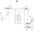
- FIG. 2 is a schematic diagram showing the configuration of the optical system of the automatic analyzer according to the present embodiment and devices arranged in the periphery thereof.
- 5A and 5B are diagrams showing how to switch the display of the remaining life on the display unit of the automatic analyzer according to the present embodiment.
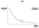
- 11 is a graph showing a range in which the remaining life is displayed in a first display manner and a range in which the remaining life is displayed in a second display manner.
- 1 is a diagram showing the configuration of a notification system including PCs of multiple automatic analyzers and a PC used by an operator replacing a light source.
- 13 is an example of a screen displayed on the automatic analyzer and the PC of the replacement worker to determine the replacement date. 13 is an example screen showing multiple candidates proposed as the remaining life display method.
- FIG. 1 is a diagram showing the overall configuration of an automatic analyzer according to this embodiment.
- the automatic analyzer 100 is composed of a conveying line 101, a rotor 102, a reagent disk 103, a reaction disk 104, a sample dispensing mechanism 105a, a reagent dispensing mechanism 105b, a stirring mechanism 106, a light source 120, a spectroscope 107, a control unit 115, a display unit 123, an input unit 124, a reaction cell cleaning mechanism 108, a nozzle cleaning mechanism 109, etc.
- the transport line 101 transports a sample rack 111 holding a sample container 110 containing a sample to a sample dispensing position 121.
- the sample dispensing mechanism 105a dispenses the sample from the sample container 110 at the sample dispensing position 121 to a reaction cell 112 (reaction container).
- the transport line 101 is further connected to a rotor 102. By rotating the rotor 102, the sample rack 111 is exchanged between other transport lines 101.
- the reagent disk 103 holds reagent containers 113 that contain reagents, and rotates and transports the reagent containers 113 to a reagent dispensing position 122 where the reagent dispensing mechanism 105b can perform a dispensing operation.
- the reagent dispensing mechanism 105b dispenses the reagent from the reagent container 113 at the reagent dispensing position 122 into the reaction cell 112.
- the reagent dispensed into the reaction cell 112 reacts with the components in the sample to be analyzed.
- the reaction disk 104 holds the reaction cell 112 and rotates to transport the reaction cell 112 to each position where the spectrometer 107, the stirring mechanism 106, the reaction cell cleaning mechanism 108, etc. are operated.
- the reaction cell 112 is kept warm by a constant temperature medium such as water in a reaction tank 203 (see FIG. 2). This promotes chemical reactions between components in the specimen and the reagent in the reaction liquid, which is a mixture of the specimen and the reagent.
- the specimen dispensing mechanism 105a aspirates the specimen to be analyzed from the specimen container 110 and dispenses it into the reaction cell 112.
- the reagent dispensing mechanism 105b aspirates the reagent corresponding to the analysis item from the reagent container 113 and dispenses it into the reaction cell 112.
- Each dispensing mechanism is equipped with an arm 118, a nozzle 116, and a dispensing mechanism motor 119.
- the arm 118 holds the nozzle 116 and a liquid level sensor 117.
- the nozzle 116 is connected to the liquid level sensor 117.
- the liquid level sensor 117 detects the presence or absence of liquid by a change in capacitance.
- a shield part 114 is installed near the position where each dispensing mechanism performs the dispensing operation.
- the dispensing mechanism motor 119 moves each dispensing mechanism up and down or in a rotational direction.
- the stirring mechanism 106 stirs the reaction liquid in the reaction cell 112 to promote the reaction between the components to be analyzed in the sample discharged from the sample container 110 into the reaction cell 112 and the reagent discharged from the reagent container 113 into the reaction cell 112.
- the light source 120 irradiates the reaction liquid that has been stirred by the stirring mechanism 106 and undergone a chemical reaction with output light.
- the spectroscope 107 separates the transmitted light that has passed through the reaction liquid. As described below, the separated transmitted light is detected by the photodetector 205 (see FIG. 2), and the absorbance determination unit 204 (see FIG. 2) calculates the absorbance based on the detection result.
- the control unit 115 is composed of a processor, memory, etc., and controls the operation of each mechanism of the automatic analysis device 100, and performs colorimetric analysis based on the absorbance measured by the optical system.
- the control unit 115 also predicts the remaining life of the current life-limited components used in the analysis (such as the light source 120) based on the operating time of the components and changes in state quantities.
- the control unit 115 may be provided in the PC used by the user (operator), or may be provided separately from the PC.
- the display unit 123 of the PC is configured with an LCD (Liquid Crystal Display) or the like, and displays the operation screen, remaining life, etc.
- the input unit 124 of the PC is configured with a keyboard, mouse, touch panel, etc., and accepts operations by the user.
- the reaction cell cleaning mechanism 108 cleans the reaction cell 112 by sucking the reaction liquid from the reaction cell 112 after colorimetric analysis and discharging detergent or the like.
- the nozzle cleaning mechanism 109 cleans the tip of the nozzle 116 of the dispensing mechanism that dispensed the sample or reagent. This removes any residue adhering to the nozzle 116, preventing it from affecting the next analysis target.
- FIG. 2 is a schematic diagram showing the optical system of the automatic analyzer according to this embodiment and the devices arranged in its periphery.
- the light source 120 is composed of one or more LED elements. When the light source 120 is composed of more than one LED element, the amount of current supplied to each LED element is set individually.
- the current detection unit 201 monitors (measures) the current flowing through the light source 120.
- the current adjustment unit 202 has a circuit that reduces the amount of current supplied to the light source 120 or turns off the power to the light source 120 at a timing that does not affect the analysis.
- reaction cell 112 Light from the light source 120 is irradiated onto the reaction cell 112, which passes through the photometric position between the light source 120 and the diffraction grating 206 while the reaction disk 104 is in operation.
- the analyte component in the specimen reacts with a reagent corresponding to the analysis item, and a substance to be measured is produced or consumed in proportion to the concentration of the analyte component.
- reaction tank water constant temperature medium
- the light irradiated onto the reaction solution light with a wavelength in an absorption region corresponding to the substance to be measured is absorbed by the substance to be measured.
- the light transmitted through the reaction solution is incident on a concave diffraction grating 206.
- the diffraction grating 206 separates the incident light into wavelengths and outputs the separated light to a photodetector 205.
- the photodetector 205 converts the amount of light into an electrical signal and outputs the electrical signal to an absorbance determination unit 204.
- the absorbance determination unit 204 calculates the absorbance based on the electrical signal output from the photodetector 205, and outputs the calculated absorbance to the control unit 115.
- the control unit 115 performs colorimetric analysis based on the absorbance output from the absorbance determination unit 204.
- the control unit 115 When performing colorimetric analysis, the control unit 115 dispenses cell blank water into all reaction cells 112 and measures the absorbance at each wavelength from 340 to 800 nm (cell blank measurement). The control unit 115 stores this measurement result as a cell blank value in a memory unit (not shown). The control unit 115 corrects the absorbance by comparing the cell blank value with the absorbance of the reaction solution to be analyzed, and outputs the corrected absorbance to the screen of the display unit 123 as measurement data.
- FIG. 3 is a diagram showing switching of the display of the remaining life on the display unit of the automatic analyzer according to this embodiment.
- an LED element constituting the light source 120 will be described as an example of a life-limited component.
- the light source 120 which is composed of LED elements, has a longer lighting life than light sources (e.g., halogen lamps) that have been conventionally used in biochemical automatic analyzers.
- the lighting life varies depending on the user's environment in which the analyzer is used.
- the lighting life of the light source 120 differs greatly between a case in which the automatic analyzer is operated for only 8 hours a day (i.e., the light source 120 is turned off for 16 hours a day) and a case in which the automatic analyzer is operated continuously for 24 hours. Therefore, in this embodiment, a uniform replacement time is not set for the light source 120, and an appropriate replacement time that reflects the environment in which the analyzer is used is proposed by predicting the remaining life.
- the remaining life predicted by the control unit 115 is not limited to the time until the life is reached, but may be the number of days until the life is reached or the date and time at which the life is reached, which are determined based on the time and the usage trend of the analyzer.
- the date and time when the light source 120 reaches the end of its life can also be considered as the time to replace the light source 120 .
- control unit 115 causes the display unit 123 to display the predicted remaining life
- multiple display methods are envisioned. For example, if there is still sufficient remaining life, a method of displaying the remaining life as a ratio (%) of the life of the original (new) light source 120 is more suitable for intuitively understanding the current usage status of the light source 120 than a method of displaying the specific number of days until the end of the life.
- the remaining life is short, it is easier for the user to understand in detail when it is time to replace the light source 120 by displaying the specific number of days until the end of the life, rather than displaying the remaining life as a ratio.
- the control unit 115 of this embodiment is configured to switch the display method of the remaining life displayed on the display unit 123 when the remaining life of the light source 120 reaches a predetermined reference value.
- the remaining life is displayed as a remaining ratio until the remaining life reaches reference value A (for example, until the time until the remaining life reaches 1,000 hours), and after the remaining life reaches reference value A, the remaining life is displayed as the number of remaining days.
- the display methods before and after the switch are not limited to the example of FIG. 3, but it is preferable that the display method before the switch is low resolution (coarse accuracy) and the display method after the switch is high resolution (fine accuracy).
- the control unit 115 uses the lighting time of the light source 120, the attenuation rate of the light intensity, the supply current value, and other information.
- the lighting time of the light source 120 cannot be counted directly, it is possible to indirectly obtain the lighting time from the usage time of the automatic analyzer 100. Since the light source 120 is basically on while the automatic analyzer 100 is running, both in standby and operation, the lighting time of the light source 120 can be indirectly obtained by multiplying the usage time of the automatic analyzer 100 by a coefficient of, for example, 0.90 to 0.99.
- the prediction accuracy is higher if the lighting time of the light source 120 is directly counted and the remaining life is predicted using that time. Therefore, in cases where control is performed such that the light source 120 is turned off during standby of the automatic analyzer 100, it is desirable to be able to count the lighting time of the light source 120.
- Figure 4 is a graph showing the range in which the remaining life is displayed in a first display method and the range in which the remaining life is displayed in a second display method.
- the horizontal axis shows the usage time of the automatic analyzer 100
- the vertical axis shows the predicted remaining time.
- the solid line on the graph indicates the range in which the remaining life is displayed in the first display method (e.g., remaining ratio)
- the dashed line on the graph indicates the range in which the remaining life is displayed in the second display method (e.g., remaining days).
- Point A on the graph indicates the timing for switching the display method.
- Point A is a predetermined reference value, and may be determined based only on the predicted remaining time, or only on the usage time, or may be determined using both the former and the latter. This reference value is determined taking into consideration a certain replacement preparation period so that the replacement work can be completed before the end of the light source 120's lifespan. For example, the timing of point A is set so that if a replacement worker places an order for the light source 120 within a specified period after point A is reached, replacement before the end of its lifespan is possible.
- FIG. 5 is a diagram showing the configuration of a notification system including the PCs of multiple automatic analyzers and a PC used by the light source replacement worker.
- the PC of each automatic analyzer is connected to the replacement worker's PC via a wired or wireless communication line.
- the PC used by the replacement worker may be a terminal device such as a smartphone.
- the light source replacement timings for the automated analyzers A through D that a single worker is in charge of are not the same, so it is difficult for the worker to keep track of the replacement timings for all of the devices. Therefore, in this embodiment, when the remaining life of the light source 120 reaches a reference value and the display method for the remaining life is switched, the control unit 115 of the automated analyzer 100 notifies the PC of the replacement worker via a communication line that the reference value has been reached. In the example of FIG. 5, the remaining life of the light source of the automated analyzer C has reached the reference value, and this has been notified to the PC of the replacement worker. This allows the replacement worker to easily know which devices need to be replaced, reducing the risk of delays in the replacement work. Note that it is preferable to notify the PC of the replacement worker when the reference value is reached, i.e., when the display method is switched, but it may be a certain period of time after that point.
- Figure 6 shows an example of a screen displayed on the automatic analyzer and the PC of the replacement worker to determine the replacement work date.
- the remaining life of the light source of automatic analyzer A has reached a reference value, and the display unit 123 displays recommended replacement dates A to C.
- the timing for displaying the recommended replacement date as in FIG. 6 is not limited to immediately after the remaining life reaches the reference value for switching the display method, but may be a predetermined time (number of days) after reaching that value.
- a reference value for displaying the recommended replacement date may be set separately from the reference value for switching the display method.
- multiple candidates for the recommended replacement date are calculated by the control unit 115 taking into consideration the usage schedule of the automatic analyzer. For example, in the case of an automatic analyzer that is not used on Wednesdays out of Monday to Friday every week, Wednesday is calculated as the recommended replacement date.
- the control unit 115 of the automatic analysis device 100 When a specific recommended replacement date is selected from among multiple recommended replacement dates by the input unit 124, the control unit 115 of the automatic analysis device 100 notifies the PC of the replacement worker of the selected recommended replacement date via a communication line.
- the PC of the automatic analysis device A selected the recommended date for B, and the PC of the replacement worker is notified of this. This has the advantage that it becomes easier for both the user and the replacement worker to adjust the replacement date, and also reduces the risk of delays in the replacement work.
- Fig. 7 is an example of a screen showing a state in which a plurality of candidates are proposed as the remaining life display method. 7, three display methods can be selected: remaining ratio, remaining time, and remaining days.
- the control unit 115 causes the display unit 123 to display the remaining life in the selected display method. This allows the user to display the remaining life in the method of their choice, making it easier for them to know when to replace the light source 120.
- the present invention is not limited to the above-described embodiment, but includes various modified examples.
- the above-described embodiment has been described using the light source 120 as an example of a component with a finite lifespan, but the present invention can be similarly applied to other components with a finite lifespan used in analysis.
- the nozzle 116 of the dispensing mechanism, the syringe (not shown) used to aspirate and dispense samples and reagents, the reaction cell 112, etc. also have a certain lifespan, so they can be similarly applied if an algorithm for predicting their lifespan can be created.
- 100...automatic analyzer 101...transport line, 102...rotor, 103...reagent disk, 104...reaction disk, 105a...specimen dispensing mechanism, 105b...reagent dispensing mechanism, 106...agitation mechanism, 107...spectrometer, 108...reaction cell cleaning mechanism, 109...nozzle cleaning mechanism, 110...specimen container, 111...specimen rack, 112...reaction cell, 113...reagent container, 114...shield, 115...control unit, 116...nozzle, 117...liquid level sensor, 118...arm, 119...dispensing mechanism motor, 120...light source, 121...specimen dispensing position, 122...reagent dispensing position, 123...display unit, 124...input unit, 203...reaction tank, 205...photodetector, 206...diffraction grating.
Landscapes
- Engineering & Computer Science (AREA)
- Quality & Reliability (AREA)
- Physics & Mathematics (AREA)
- Health & Medical Sciences (AREA)
- Life Sciences & Earth Sciences (AREA)
- Chemical & Material Sciences (AREA)
- Analytical Chemistry (AREA)
- Biochemistry (AREA)
- General Health & Medical Sciences (AREA)
- General Physics & Mathematics (AREA)
- Immunology (AREA)
- Pathology (AREA)
- Automatic Analysis And Handling Materials Therefor (AREA)
Priority Applications (3)
| Application Number | Priority Date | Filing Date | Title |
|---|---|---|---|
| JP2024555699A JPWO2024075511A1 (https=) | 2022-10-07 | 2023-09-19 | |
| CN202380067140.8A CN119895266A (zh) | 2022-10-07 | 2023-09-19 | 自动分析装置 |
| EP23874640.8A EP4600655A1 (en) | 2022-10-07 | 2023-09-19 | Automated analysis device |
Applications Claiming Priority (2)
| Application Number | Priority Date | Filing Date | Title |
|---|---|---|---|
| JP2022-162359 | 2022-10-07 | ||
| JP2022162359 | 2022-10-07 |
Publications (1)
| Publication Number | Publication Date |
|---|---|
| WO2024075511A1 true WO2024075511A1 (ja) | 2024-04-11 |
Family
ID=90607689
Family Applications (1)
| Application Number | Title | Priority Date | Filing Date |
|---|---|---|---|
| PCT/JP2023/033904 Ceased WO2024075511A1 (ja) | 2022-10-07 | 2023-09-19 | 自動分析装置 |
Country Status (4)
| Country | Link |
|---|---|
| EP (1) | EP4600655A1 (https=) |
| JP (1) | JPWO2024075511A1 (https=) |
| CN (1) | CN119895266A (https=) |
| WO (1) | WO2024075511A1 (https=) |
Citations (3)
| Publication number | Priority date | Publication date | Assignee | Title |
|---|---|---|---|---|
| JP2010107478A (ja) * | 2008-10-31 | 2010-05-13 | Sysmex Corp | 検体分析装置、検体分析装置における試薬情報の表示方法およびコンピュータプログラム |
| JP2014032022A (ja) * | 2012-08-01 | 2014-02-20 | Shimadzu Corp | 分析装置制御システム、及び分析装置制御システム用プログラム |
| WO2022196346A1 (ja) * | 2021-03-16 | 2022-09-22 | 株式会社日立ハイテク | 自動分析装置 |
Family Cites Families (6)
| Publication number | Priority date | Publication date | Assignee | Title |
|---|---|---|---|---|
| US5915932A (en) * | 1990-02-02 | 1999-06-29 | Isco, Inc. | Peristaltic pump having a roller support |
| JPH05264559A (ja) * | 1992-03-18 | 1993-10-12 | Hitachi Ltd | 自動分析装置 |
| JPH05281001A (ja) * | 1992-04-03 | 1993-10-29 | Fuji Electric Co Ltd | 部品の寿命時間予測装置 |
| JP4508163B2 (ja) * | 2006-06-23 | 2010-07-21 | オムロン株式会社 | 温度検出構造および電子機器 |
| JP4893703B2 (ja) * | 2008-07-11 | 2012-03-07 | トヨタ自動車株式会社 | 蓄電装置の劣化表示システムおよび蓄電装置の劣化表示方法 |
| JP2020194583A (ja) * | 2020-08-21 | 2020-12-03 | ファナック株式会社 | サービスセンタ管理装置 |
-
2023
- 2023-09-19 WO PCT/JP2023/033904 patent/WO2024075511A1/ja not_active Ceased
- 2023-09-19 JP JP2024555699A patent/JPWO2024075511A1/ja active Pending
- 2023-09-19 CN CN202380067140.8A patent/CN119895266A/zh active Pending
- 2023-09-19 EP EP23874640.8A patent/EP4600655A1/en active Pending
Patent Citations (3)
| Publication number | Priority date | Publication date | Assignee | Title |
|---|---|---|---|---|
| JP2010107478A (ja) * | 2008-10-31 | 2010-05-13 | Sysmex Corp | 検体分析装置、検体分析装置における試薬情報の表示方法およびコンピュータプログラム |
| JP2014032022A (ja) * | 2012-08-01 | 2014-02-20 | Shimadzu Corp | 分析装置制御システム、及び分析装置制御システム用プログラム |
| WO2022196346A1 (ja) * | 2021-03-16 | 2022-09-22 | 株式会社日立ハイテク | 自動分析装置 |
Also Published As
| Publication number | Publication date |
|---|---|
| CN119895266A (zh) | 2025-04-25 |
| JPWO2024075511A1 (https=) | 2024-04-11 |
| EP4600655A1 (en) | 2025-08-13 |
Similar Documents
| Publication | Publication Date | Title |
|---|---|---|
| JP2024169608A (ja) | 自動分析装置及び自動分析方法 | |
| US8460935B2 (en) | Sample analyzer, sample analyzing method, and computer program product | |
| US20140119994A1 (en) | Sample analyzer | |
| EP1887356B1 (en) | Automatic analyzer | |
| EP1835292A1 (en) | Automatic analyzer | |
| JPWO2017138285A1 (ja) | 自動分析装置 | |
| JP2022164188A (ja) | 自動分析装置 | |
| JP6294186B2 (ja) | 自動分析装置 | |
| US20190361042A1 (en) | Automatic analyzer | |
| EP2015078A1 (en) | Automatic analyzer and analysis method using the same | |
| WO2020137140A1 (ja) | 自動分析装置および自動分析システム、ならびに試料の自動分析方法 | |
| JP7603142B2 (ja) | 自動分析装置 | |
| JP2010261823A (ja) | 自動分析装置 | |
| CN102292644B (zh) | 样本分析装置 | |
| JP5373573B2 (ja) | 自動分析装置、および自動分析装置の光源ランプ交換方法 | |
| EP4600655A1 (en) | Automated analysis device | |
| JP6279234B2 (ja) | 自動分析装置 | |
| EP3514548A1 (en) | Automatic analysis apparatus | |
| JP6737529B2 (ja) | 自動分析装置 | |
| WO2024202894A1 (ja) | 分析装置、判定方法、及び予測方法 | |
| EP4303576B1 (en) | Electrolyte measurement device, and method for determining abnormality in electrolyte concentration measurement unit | |
| EP3561519B1 (en) | Apparatus and method for automated analysis | |
| JPS63175749A (ja) | 透過光測定装置 | |
| JP4884275B2 (ja) | 自動分析装置 | |
| EP2154512A1 (en) | Automated analyzer |
Legal Events
| Date | Code | Title | Description |
|---|---|---|---|
| 121 | Ep: the epo has been informed by wipo that ep was designated in this application |
Ref document number: 23874640 Country of ref document: EP Kind code of ref document: A1 |
|
| DPE1 | Request for preliminary examination filed after expiration of 19th month from priority date (pct application filed from 20040101) | ||
| WWE | Wipo information: entry into national phase |
Ref document number: 2024555699 Country of ref document: JP |
|
| WWE | Wipo information: entry into national phase |
Ref document number: 202380067140.8 Country of ref document: CN |
|
| WWP | Wipo information: published in national office |
Ref document number: 202380067140.8 Country of ref document: CN |
|
| WWE | Wipo information: entry into national phase |
Ref document number: 2023874640 Country of ref document: EP |
|
| NENP | Non-entry into the national phase |
Ref country code: DE |
|
| ENP | Entry into the national phase |
Ref document number: 2023874640 Country of ref document: EP Effective date: 20250507 |
|
| WWP | Wipo information: published in national office |
Ref document number: 2023874640 Country of ref document: EP |