WO2024075511A1 - 自動分析装置 - Google Patents
自動分析装置 Download PDFInfo
- Publication number
- WO2024075511A1 WO2024075511A1 PCT/JP2023/033904 JP2023033904W WO2024075511A1 WO 2024075511 A1 WO2024075511 A1 WO 2024075511A1 JP 2023033904 W JP2023033904 W JP 2023033904W WO 2024075511 A1 WO2024075511 A1 WO 2024075511A1
- Authority
- WO
- WIPO (PCT)
- Prior art keywords
- life
- remaining life
- control unit
- remaining
- component
- Prior art date
Links
- 238000004458 analytical method Methods 0.000 title claims abstract description 20
- 238000000034 method Methods 0.000 claims abstract description 38
- 239000012491 analyte Substances 0.000 claims description 6
- 238000004891 communication Methods 0.000 claims description 5
- 238000006243 chemical reaction Methods 0.000 description 40
- 230000007246 mechanism Effects 0.000 description 30
- 239000003153 chemical reaction reagent Substances 0.000 description 28
- 238000002835 absorbance Methods 0.000 description 13
- 238000010586 diagram Methods 0.000 description 8
- 238000004140 cleaning Methods 0.000 description 7
- 230000032258 transport Effects 0.000 description 7
- 239000012295 chemical reaction liquid Substances 0.000 description 5
- 239000007788 liquid Substances 0.000 description 5
- 238000003756 stirring Methods 0.000 description 5
- 238000004737 colorimetric analysis Methods 0.000 description 4
- 230000003287 optical effect Effects 0.000 description 4
- 238000005259 measurement Methods 0.000 description 3
- 239000000126 substance Substances 0.000 description 3
- XLYOFNOQVPJJNP-UHFFFAOYSA-N water Substances O XLYOFNOQVPJJNP-UHFFFAOYSA-N 0.000 description 3
- 230000001934 delay Effects 0.000 description 2
- 238000001514 detection method Methods 0.000 description 2
- 229910052736 halogen Inorganic materials 0.000 description 2
- 150000002367 halogens Chemical class 0.000 description 2
- 238000002360 preparation method Methods 0.000 description 2
- 238000010521 absorption reaction Methods 0.000 description 1
- 238000013019 agitation Methods 0.000 description 1
- 230000008901 benefit Effects 0.000 description 1
- 239000008280 blood Substances 0.000 description 1
- 210000004369 blood Anatomy 0.000 description 1
- 230000008859 change Effects 0.000 description 1
- 239000003599 detergent Substances 0.000 description 1
- 238000007599 discharging Methods 0.000 description 1
- 238000005516 engineering process Methods 0.000 description 1
- 230000006870 function Effects 0.000 description 1
- 239000004973 liquid crystal related substance Substances 0.000 description 1
- 239000000203 mixture Substances 0.000 description 1
Images


Classifications
-
- G—PHYSICS
- G01—MEASURING; TESTING
- G01N—INVESTIGATING OR ANALYSING MATERIALS BY DETERMINING THEIR CHEMICAL OR PHYSICAL PROPERTIES
- G01N21/00—Investigating or analysing materials by the use of optical means, i.e. using sub-millimetre waves, infrared, visible or ultraviolet light
-
- G—PHYSICS
- G01—MEASURING; TESTING
- G01N—INVESTIGATING OR ANALYSING MATERIALS BY DETERMINING THEIR CHEMICAL OR PHYSICAL PROPERTIES
- G01N35/00—Automatic analysis not limited to methods or materials provided for in any single one of groups G01N1/00 - G01N33/00; Handling materials therefor
Definitions
- the present invention relates to an automatic analyzer.
- a component with a certain lifespan is used.
- a light source is one of the important components that affect the analytical performance. Light emitted from the light source passes through a reaction solution in which a reagent and a sample are mixed, is dispersed into a specific number of wavelengths by a spectroscope, and is detected by a detector.
- automatic analyzers equipped with a light source using an LED instead of a halogen lamp that was conventionally used have been developed. LED light sources generally have a long lighting lifespan, but the lighting lifespan varies depending on the usage environment. Therefore, it is important to predict the usable time (remaining lifespan) of the light source and grasp the appropriate replacement time.
- Patent Document 1 discloses a method for predicting the remaining lifespan of an LED, which predicts the remaining lifespan (remaining lifespan) from changes in the correction rate (dimming correction rate) of an adjustment function for keeping the amount of light constant.
- Patent Document 1 also discloses that the predicted remaining life can be displayed as a remaining time or as a remaining number of days obtained by dividing the remaining time by the average lighting time per day.
- the predicted remaining lifespan is displayed in a single format from start to finish, which can make it difficult to grasp the current usage status or the specific replacement time. For example, if the remaining time is displayed consistently from start to finish, the user must calculate when the lifespan will end. Also, if the number of remaining days is displayed consistently from start to finish, the prediction accuracy of the remaining days, especially displayed at the beginning, is not high, making it difficult to intuitively grasp the current usage status.
- the object of the present invention is to provide an automatic analyzer that allows the user to easily understand the current usage status and replacement timing of components with a limited life span.
- the present invention provides an automated analyzer for analyzing an analyte in a sample, the automated analyzer comprising a finite-life component used to perform the analysis, a control unit for predicting the remaining life of the finite-life component, and a display unit capable of displaying the remaining life in different ways, and the control unit switches the display method of the remaining life displayed on the display unit when the remaining life of the finite-life component reaches a predetermined reference value.
- the present invention provides an automated analyzer for analyzing an analyte in a sample, the automated analyzer comprising a finite-life component used for performing the analysis, a control unit for predicting the remaining life of the finite-life component, an input unit for selecting a specific candidate from a plurality of candidates as a method for displaying the remaining life, and a display unit for displaying the remaining life using the method selected by the input unit.
- the display method can be switched depending on the remaining life of a life-limited component, making it possible to provide an automatic analyzer that allows the user to easily understand the current usage status and replacement timing of a life-limited component.
- FIG. 1 is a diagram showing the overall configuration of an automatic analyzer according to an embodiment of the present invention.
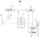
- FIG. 2 is a schematic diagram showing the configuration of the optical system of the automatic analyzer according to the present embodiment and devices arranged in the periphery thereof.
- 5A and 5B are diagrams showing how to switch the display of the remaining life on the display unit of the automatic analyzer according to the present embodiment.
- 11 is a graph showing a range in which the remaining life is displayed in a first display manner and a range in which the remaining life is displayed in a second display manner.
- 1 is a diagram showing the configuration of a notification system including PCs of multiple automatic analyzers and a PC used by an operator replacing a light source.
- 13 is an example of a screen displayed on the automatic analyzer and the PC of the replacement worker to determine the replacement date. 13 is an example screen showing multiple candidates proposed as the remaining life display method.
- FIG. 1 is a diagram showing the overall configuration of an automatic analyzer according to this embodiment.
- the automatic analyzer 100 is composed of a conveying line 101, a rotor 102, a reagent disk 103, a reaction disk 104, a sample dispensing mechanism 105a, a reagent dispensing mechanism 105b, a stirring mechanism 106, a light source 120, a spectroscope 107, a control unit 115, a display unit 123, an input unit 124, a reaction cell cleaning mechanism 108, a nozzle cleaning mechanism 109, etc.
- the transport line 101 transports a sample rack 111 holding a sample container 110 containing a sample to a sample dispensing position 121.
- the sample dispensing mechanism 105a dispenses the sample from the sample container 110 at the sample dispensing position 121 to a reaction cell 112 (reaction container).
- the transport line 101 is further connected to a rotor 102. By rotating the rotor 102, the sample rack 111 is exchanged between other transport lines 101.
- the reagent disk 103 holds reagent containers 113 that contain reagents, and rotates and transports the reagent containers 113 to a reagent dispensing position 122 where the reagent dispensing mechanism 105b can perform a dispensing operation.
- the reagent dispensing mechanism 105b dispenses the reagent from the reagent container 113 at the reagent dispensing position 122 into the reaction cell 112.
- the reagent dispensed into the reaction cell 112 reacts with the components in the sample to be analyzed.
- the reaction disk 104 holds the reaction cell 112 and rotates to transport the reaction cell 112 to each position where the spectrometer 107, the stirring mechanism 106, the reaction cell cleaning mechanism 108, etc. are operated.
- the reaction cell 112 is kept warm by a constant temperature medium such as water in a reaction tank 203 (see FIG. 2). This promotes chemical reactions between components in the specimen and the reagent in the reaction liquid, which is a mixture of the specimen and the reagent.
- the specimen dispensing mechanism 105a aspirates the specimen to be analyzed from the specimen container 110 and dispenses it into the reaction cell 112.
- the reagent dispensing mechanism 105b aspirates the reagent corresponding to the analysis item from the reagent container 113 and dispenses it into the reaction cell 112.
- Each dispensing mechanism is equipped with an arm 118, a nozzle 116, and a dispensing mechanism motor 119.
- the arm 118 holds the nozzle 116 and a liquid level sensor 117.
- the nozzle 116 is connected to the liquid level sensor 117.
- the liquid level sensor 117 detects the presence or absence of liquid by a change in capacitance.
- a shield part 114 is installed near the position where each dispensing mechanism performs the dispensing operation.
- the dispensing mechanism motor 119 moves each dispensing mechanism up and down or in a rotational direction.
- the stirring mechanism 106 stirs the reaction liquid in the reaction cell 112 to promote the reaction between the components to be analyzed in the sample discharged from the sample container 110 into the reaction cell 112 and the reagent discharged from the reagent container 113 into the reaction cell 112.
- the light source 120 irradiates the reaction liquid that has been stirred by the stirring mechanism 106 and undergone a chemical reaction with output light.
- the spectroscope 107 separates the transmitted light that has passed through the reaction liquid. As described below, the separated transmitted light is detected by the photodetector 205 (see FIG. 2), and the absorbance determination unit 204 (see FIG. 2) calculates the absorbance based on the detection result.
- the control unit 115 is composed of a processor, memory, etc., and controls the operation of each mechanism of the automatic analysis device 100, and performs colorimetric analysis based on the absorbance measured by the optical system.
- the control unit 115 also predicts the remaining life of the current life-limited components used in the analysis (such as the light source 120) based on the operating time of the components and changes in state quantities.
- the control unit 115 may be provided in the PC used by the user (operator), or may be provided separately from the PC.
- the display unit 123 of the PC is configured with an LCD (Liquid Crystal Display) or the like, and displays the operation screen, remaining life, etc.
- the input unit 124 of the PC is configured with a keyboard, mouse, touch panel, etc., and accepts operations by the user.
- the reaction cell cleaning mechanism 108 cleans the reaction cell 112 by sucking the reaction liquid from the reaction cell 112 after colorimetric analysis and discharging detergent or the like.
- the nozzle cleaning mechanism 109 cleans the tip of the nozzle 116 of the dispensing mechanism that dispensed the sample or reagent. This removes any residue adhering to the nozzle 116, preventing it from affecting the next analysis target.
- FIG. 2 is a schematic diagram showing the optical system of the automatic analyzer according to this embodiment and the devices arranged in its periphery.
- the light source 120 is composed of one or more LED elements. When the light source 120 is composed of more than one LED element, the amount of current supplied to each LED element is set individually.
- the current detection unit 201 monitors (measures) the current flowing through the light source 120.
- the current adjustment unit 202 has a circuit that reduces the amount of current supplied to the light source 120 or turns off the power to the light source 120 at a timing that does not affect the analysis.
- reaction cell 112 Light from the light source 120 is irradiated onto the reaction cell 112, which passes through the photometric position between the light source 120 and the diffraction grating 206 while the reaction disk 104 is in operation.
- the analyte component in the specimen reacts with a reagent corresponding to the analysis item, and a substance to be measured is produced or consumed in proportion to the concentration of the analyte component.
- reaction tank water constant temperature medium
- the light irradiated onto the reaction solution light with a wavelength in an absorption region corresponding to the substance to be measured is absorbed by the substance to be measured.
- the light transmitted through the reaction solution is incident on a concave diffraction grating 206.
- the diffraction grating 206 separates the incident light into wavelengths and outputs the separated light to a photodetector 205.
- the photodetector 205 converts the amount of light into an electrical signal and outputs the electrical signal to an absorbance determination unit 204.
- the absorbance determination unit 204 calculates the absorbance based on the electrical signal output from the photodetector 205, and outputs the calculated absorbance to the control unit 115.
- the control unit 115 performs colorimetric analysis based on the absorbance output from the absorbance determination unit 204.
- the control unit 115 When performing colorimetric analysis, the control unit 115 dispenses cell blank water into all reaction cells 112 and measures the absorbance at each wavelength from 340 to 800 nm (cell blank measurement). The control unit 115 stores this measurement result as a cell blank value in a memory unit (not shown). The control unit 115 corrects the absorbance by comparing the cell blank value with the absorbance of the reaction solution to be analyzed, and outputs the corrected absorbance to the screen of the display unit 123 as measurement data.
- FIG. 3 is a diagram showing switching of the display of the remaining life on the display unit of the automatic analyzer according to this embodiment.
- an LED element constituting the light source 120 will be described as an example of a life-limited component.
- the light source 120 which is composed of LED elements, has a longer lighting life than light sources (e.g., halogen lamps) that have been conventionally used in biochemical automatic analyzers.
- the lighting life varies depending on the user's environment in which the analyzer is used.
- the lighting life of the light source 120 differs greatly between a case in which the automatic analyzer is operated for only 8 hours a day (i.e., the light source 120 is turned off for 16 hours a day) and a case in which the automatic analyzer is operated continuously for 24 hours. Therefore, in this embodiment, a uniform replacement time is not set for the light source 120, and an appropriate replacement time that reflects the environment in which the analyzer is used is proposed by predicting the remaining life.
- the remaining life predicted by the control unit 115 is not limited to the time until the life is reached, but may be the number of days until the life is reached or the date and time at which the life is reached, which are determined based on the time and the usage trend of the analyzer.
- the date and time when the light source 120 reaches the end of its life can also be considered as the time to replace the light source 120 .
- control unit 115 causes the display unit 123 to display the predicted remaining life
- multiple display methods are envisioned. For example, if there is still sufficient remaining life, a method of displaying the remaining life as a ratio (%) of the life of the original (new) light source 120 is more suitable for intuitively understanding the current usage status of the light source 120 than a method of displaying the specific number of days until the end of the life.
- the remaining life is short, it is easier for the user to understand in detail when it is time to replace the light source 120 by displaying the specific number of days until the end of the life, rather than displaying the remaining life as a ratio.
- the control unit 115 of this embodiment is configured to switch the display method of the remaining life displayed on the display unit 123 when the remaining life of the light source 120 reaches a predetermined reference value.
- the remaining life is displayed as a remaining ratio until the remaining life reaches reference value A (for example, until the time until the remaining life reaches 1,000 hours), and after the remaining life reaches reference value A, the remaining life is displayed as the number of remaining days.
- the display methods before and after the switch are not limited to the example of FIG. 3, but it is preferable that the display method before the switch is low resolution (coarse accuracy) and the display method after the switch is high resolution (fine accuracy).
- the control unit 115 uses the lighting time of the light source 120, the attenuation rate of the light intensity, the supply current value, and other information.
- the lighting time of the light source 120 cannot be counted directly, it is possible to indirectly obtain the lighting time from the usage time of the automatic analyzer 100. Since the light source 120 is basically on while the automatic analyzer 100 is running, both in standby and operation, the lighting time of the light source 120 can be indirectly obtained by multiplying the usage time of the automatic analyzer 100 by a coefficient of, for example, 0.90 to 0.99.
- the prediction accuracy is higher if the lighting time of the light source 120 is directly counted and the remaining life is predicted using that time. Therefore, in cases where control is performed such that the light source 120 is turned off during standby of the automatic analyzer 100, it is desirable to be able to count the lighting time of the light source 120.
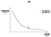
- Figure 4 is a graph showing the range in which the remaining life is displayed in a first display method and the range in which the remaining life is displayed in a second display method.
- the horizontal axis shows the usage time of the automatic analyzer 100
- the vertical axis shows the predicted remaining time.
- the solid line on the graph indicates the range in which the remaining life is displayed in the first display method (e.g., remaining ratio)
- the dashed line on the graph indicates the range in which the remaining life is displayed in the second display method (e.g., remaining days).
- Point A on the graph indicates the timing for switching the display method.
- Point A is a predetermined reference value, and may be determined based only on the predicted remaining time, or only on the usage time, or may be determined using both the former and the latter. This reference value is determined taking into consideration a certain replacement preparation period so that the replacement work can be completed before the end of the light source 120's lifespan. For example, the timing of point A is set so that if a replacement worker places an order for the light source 120 within a specified period after point A is reached, replacement before the end of its lifespan is possible.
- FIG. 5 is a diagram showing the configuration of a notification system including the PCs of multiple automatic analyzers and a PC used by the light source replacement worker.
- the PC of each automatic analyzer is connected to the replacement worker's PC via a wired or wireless communication line.
- the PC used by the replacement worker may be a terminal device such as a smartphone.
- the light source replacement timings for the automated analyzers A through D that a single worker is in charge of are not the same, so it is difficult for the worker to keep track of the replacement timings for all of the devices. Therefore, in this embodiment, when the remaining life of the light source 120 reaches a reference value and the display method for the remaining life is switched, the control unit 115 of the automated analyzer 100 notifies the PC of the replacement worker via a communication line that the reference value has been reached. In the example of FIG. 5, the remaining life of the light source of the automated analyzer C has reached the reference value, and this has been notified to the PC of the replacement worker. This allows the replacement worker to easily know which devices need to be replaced, reducing the risk of delays in the replacement work. Note that it is preferable to notify the PC of the replacement worker when the reference value is reached, i.e., when the display method is switched, but it may be a certain period of time after that point.
- Figure 6 shows an example of a screen displayed on the automatic analyzer and the PC of the replacement worker to determine the replacement work date.
- the remaining life of the light source of automatic analyzer A has reached a reference value, and the display unit 123 displays recommended replacement dates A to C.
- the timing for displaying the recommended replacement date as in FIG. 6 is not limited to immediately after the remaining life reaches the reference value for switching the display method, but may be a predetermined time (number of days) after reaching that value.
- a reference value for displaying the recommended replacement date may be set separately from the reference value for switching the display method.
- multiple candidates for the recommended replacement date are calculated by the control unit 115 taking into consideration the usage schedule of the automatic analyzer. For example, in the case of an automatic analyzer that is not used on Wednesdays out of Monday to Friday every week, Wednesday is calculated as the recommended replacement date.
- the control unit 115 of the automatic analysis device 100 When a specific recommended replacement date is selected from among multiple recommended replacement dates by the input unit 124, the control unit 115 of the automatic analysis device 100 notifies the PC of the replacement worker of the selected recommended replacement date via a communication line.
- the PC of the automatic analysis device A selected the recommended date for B, and the PC of the replacement worker is notified of this. This has the advantage that it becomes easier for both the user and the replacement worker to adjust the replacement date, and also reduces the risk of delays in the replacement work.
- Fig. 7 is an example of a screen showing a state in which a plurality of candidates are proposed as the remaining life display method. 7, three display methods can be selected: remaining ratio, remaining time, and remaining days.
- the control unit 115 causes the display unit 123 to display the remaining life in the selected display method. This allows the user to display the remaining life in the method of their choice, making it easier for them to know when to replace the light source 120.
- the present invention is not limited to the above-described embodiment, but includes various modified examples.
- the above-described embodiment has been described using the light source 120 as an example of a component with a finite lifespan, but the present invention can be similarly applied to other components with a finite lifespan used in analysis.
- the nozzle 116 of the dispensing mechanism, the syringe (not shown) used to aspirate and dispense samples and reagents, the reaction cell 112, etc. also have a certain lifespan, so they can be similarly applied if an algorithm for predicting their lifespan can be created.
- 100...automatic analyzer 101...transport line, 102...rotor, 103...reagent disk, 104...reaction disk, 105a...specimen dispensing mechanism, 105b...reagent dispensing mechanism, 106...agitation mechanism, 107...spectrometer, 108...reaction cell cleaning mechanism, 109...nozzle cleaning mechanism, 110...specimen container, 111...specimen rack, 112...reaction cell, 113...reagent container, 114...shield, 115...control unit, 116...nozzle, 117...liquid level sensor, 118...arm, 119...dispensing mechanism motor, 120...light source, 121...specimen dispensing position, 122...reagent dispensing position, 123...display unit, 124...input unit, 203...reaction tank, 205...photodetector, 206...diffraction grating.
Landscapes
- Physics & Mathematics (AREA)
- Health & Medical Sciences (AREA)
- Life Sciences & Earth Sciences (AREA)
- Chemical & Material Sciences (AREA)
- Analytical Chemistry (AREA)
- Biochemistry (AREA)
- General Health & Medical Sciences (AREA)
- General Physics & Mathematics (AREA)
- Immunology (AREA)
- Pathology (AREA)
- Automatic Analysis And Handling Materials Therefor (AREA)
Abstract
本発明の目的は、有寿命部材の現在の使用状況や交換時期をユーザが把握し易い自動分析装置を提供することにある。そのために、本発明は、検体中の分析対象を分析する自動分析装置において、分析を行うために使用する有寿命部材と、前記有寿命部材の残存寿命を予測する制御部と、前記残存寿命を異なる方式で表示し得る表示部と、を備え、前記制御部は、前記有寿命部材の前記残存寿命が予め定めた基準値に達した場合、前記表示部に表示させる前記残存寿命の表示方式を切り替える。
Description
本発明は、自動分析装置に関する。
血液等の検体を分析する自動分析装置では、一定の寿命を有する有寿命部材が用いられている。例えば光源は、分析性能を左右する重要な部品の一つである。光源から出た光は、試薬と検体を混合した反応液を通過し、分光器によって特定数の波長に分光され、検出器によって検出される。近年、従来用いられていたハロゲンランプの代わりに、LEDを用いた光源を搭載した自動分析装置が開発されている。LED光源は、一般的に長い点灯寿命を有するが、その点灯寿命は使用環境によって変化する。したがって、光源の使用可能時間(残存寿命)を予測し、適切な交換時期を把握することが重要である。LEDの残存寿命を予測する手法として、例えば特許文献1には、光量を一定に保つための調整機能の補正率(調光補正率)の変化から残存寿命(余命)を予測することが開示されている。
また、特許文献1には、予測した残存寿命を、残存時間、又は、残存時間を1日当たりの平均点灯時間で除算して得られる残存日数、として表示することも開示されている。
また、特許文献1には、予測した残存寿命を、残存時間、又は、残存時間を1日当たりの平均点灯時間で除算して得られる残存日数、として表示することも開示されている。
しかしながら、特許文献1に記載の技術では、予測した残存寿命を最初から最後まで単一の表示形式で表示し続けるため、現在の使用状況を把握し難い場合や、具体的な交換時期を把握し難い場合があった。例えば、最初から最後まで一貫して残存時間で表示される場合、寿命の到達時期はユーザ自身が算出する必要がある。また、最初から最後まで一貫して残存日数で表示される場合、特に最初の頃に表示される残存日数の予測精度は高くなく、現在の使用状況を直感的に把握するのも難しい。
本発明の目的は、有寿命部材の現在の使用状況や交換時期をユーザが把握し易い自動分析装置を提供することにある。
上記目的を達成するために、本発明は、検体中の分析対象を分析する自動分析装置において、分析を行うために使用する有寿命部材と、前記有寿命部材の残存寿命を予測する制御部と、前記残存寿命を異なる方式で表示し得る表示部と、を備え、前記制御部は、前記有寿命部材の前記残存寿命が予め定めた基準値に達した場合、前記表示部に表示させる前記残存寿命の表示方式を切り替える。
あるいは、上記目的を達成するために、本発明は、検体中の分析対象を分析する自動分析装置において、分析を行うために使用する有寿命部材と、前記有寿命部材の残存寿命を予測する制御部と、前記残存寿命を表示する方式として複数の候補から特定の候補を選択する入力部と、前記入力部で選択された方式により前記残存寿命を表示する表示部と、を備える。
本発明によれば、有寿命部材の残存寿命に応じてその表示方式が切り替えられるので、有寿命部材の現在の使用状況や交換時期をユーザが把握し易い自動分析装置を提供することが可能となる。
発明の実施形態を図面に基づいて詳細に説明する。
まず、図1を用いて、本発明の実施形態に係る自動分析装置100の全体構成を説明する。図1は、本実施形態に係る自動分析装置の全体構成図である。
図1に示すように、自動分析装置100は、搬送ライン101、ローター102、試薬ディスク103、反応ディスク104、検体分注機構105a、試薬分注機構105b、攪拌機構106、光源120、分光器107、制御部115、表示部123、入力部124、反応セル洗浄機構108、ノズル洗浄機構109等から構成される。
搬送ライン101は、検体を収容する検体容器110を保持する検体ラック111を、検体分注位置121まで移送する。検体分注機構105aは、検体分注位置121にある検体容器110から反応セル112(反応容器)へ検体を分注する。搬送ライン101は更に、ローター102と接続されている。ローター102を回転させることにより、他の搬送ライン101との間で検体ラック111のやり取りが行われる。
試薬ディスク103は、試薬を収容する試薬容器113を保持し、試薬分注機構105bが分注動作を行える試薬分注位置122まで試薬容器113を回転移送する。試薬分注機構105bは、試薬分注位置122にある試薬容器113から反応セル112へ試薬を分注する。なお、反応セル112へ分注された試薬は、分析対象となる検体中の成分と反応する。
反応ディスク104は、反応セル112を保持し、分光器107、攪拌機構106、反応セル洗浄機構108等が動作する各位置まで、反応セル112を回転移送する。なお、反応セル112は、反応槽203(図2参照)内の水等の恒温媒体によって保温される。
これにより、検体と試薬との混合物である反応液において、検体中の成分と試薬の化学反応が促進される。
これにより、検体と試薬との混合物である反応液において、検体中の成分と試薬の化学反応が促進される。
検体分注機構105aは、分析対象の検体を検体容器110から吸引し、反応セル112に吐出する。試薬分注機構105bは、分析項目に対応する試薬を試薬容器113から吸引し、反応セル112に吐出する。各分注機構は、アーム118、ノズル116、分注機構用モーター119を備える。アーム118は、ノズル116と液面センサ117を保持する。ノズル116は、液面センサ117に接続されている。液面センサ117は、静電容量変化により液体の有無を検出する。各分注機構が分注動作を行う位置の近傍には、シールド部114が設置される。分注機構用モーター119は、各分注機構を上下方向又は回転方向に移動させる。
攪拌機構106は、検体容器110から反応セル112に吐出された検体中の分析対象成分と、試薬容器113から反応セル112に吐出された試薬の反応を促進するために、反応セル112中の反応液を攪拌する。
光源120は、攪拌機構106により攪拌され化学反応した反応液に出力光を照射する。分光器107は、反応液を通過した透過光を分光する。分光された透過光は、後述のように、光検出器205(図2参照)によって検知され、その検知結果に基づいて吸光度判定部204(図2参照)が吸光度を算出する。
制御部115は、プロセッサ、メモリ等から構成され、自動分析装置100の各機構の動作を制御したり、光学系で測定された吸光度に基づいて比色分析を行ったりする。また、制御部115は、分析を行うために使用される有寿命部材(光源120など)の動作時間や状態量変化等から現在の有寿命部材の残存寿命を予測したりする。なお、制御部115は、ユーザ(オペレータ)が使用するPCに設けられるものでも良いし、当該PCとは別に設けられるものでも良い。
PCの表示部123は、LCD(Liquid Crystal Display)等により構成され、操作画面や残存寿命等を表示する。また、PCの入力部124は、キーボード、マウス、タッチパネル等により構成され、ユーザによる操作を受け付ける。
反応セル洗浄機構108は、比色分析が終了した反応セル112から反応液を吸引し、洗剤等を吐出することで、反応セル112の洗浄を行う。ノズル洗浄機構109は、検体又は試薬を分注した分注機構のノズル116の先端を洗浄する。これにより、ノズル116に付着した残留物が取り除かれ、次の分析対象に影響を及ぼすのを防止できる。
次に、図2を用いて、本発明の実施形態に係る自動分析装置100における光学系の詳細を説明する。図2は、本実施形態に係る自動分析装置の光学系とその周辺に配置される装置を示す概略構成図である。
光源120は、1つ又は複数のLED素子で構成される。なお、光源120が複数のLED素子で構成される場合、それぞれのLED素子へ供給される電流量は個別に設定される。電流検出部201は、光源120に流れる電流を監視(測定)する。電流調整部202は、分析に影響しないタイミングで、光源120に供給する電流量を低下させたり、光源120の電源をOFFにしたりする回路を有する。
光源120からの光は、反応ディスク104の動作中に、光源120と回折格子206間の測光位置を通過する反応セル112に照射される。反応セル112内の反応液では、検体中の分析対象成分と、分析項目に対応する試薬とが反応して、その分析対象成分の濃度に比例して測光対象物質が生成又は消費される。なお、反応槽203と反応セル112の間には、反応槽水(恒温媒体)がある。
反応液に照射された光のうち、測光対象物質に応じた吸収領域の波長の光は、測光対象物質に吸収される。反応液を透過した光は、凹状の回折格子206に入射する。回折格子206は、入射光を波長毎に分光し、分光された光を光検出器205に出力する。光検出器205は、光量を電気信号に変換し、その電気信号を吸光度判定部204に出力する。
吸光度判定部204は、光検出器205から出力された電気信号に基づいて吸光度を算出し、算出した吸光度を制御部115へ出力する。制御部115は、吸光度判定部204から出力された吸光度に基づいて比色分析を行う。
吸光度判定部204は、光検出器205から出力された電気信号に基づいて吸光度を算出し、算出した吸光度を制御部115へ出力する。制御部115は、吸光度判定部204から出力された吸光度に基づいて比色分析を行う。
比色分析を実施するに際して、制御部115は、全ての反応セル112に対し、セルブランク水を分注し、340~800nmの各波長の吸光度を測定する(セルブランク測定)。制御部115は、この測定結果をセルブランク値として、図示しない記憶部に記憶する。制御部115は、セルブランク値と分析対象の反応液の吸光度とを比較することで吸光度を補正し、補正した吸光度を測定データとして表示部123の画面に出力する。
次に、図3を用いて、本発明の実施形態に係る自動分析装置100における有寿命部材の残存寿命を表示する方法について説明する。図3は、本実施形態に係る自動分析装置の表示部における残存寿命の表示の切り替えを示す図である。以下では、有寿命部材として光源120を構成するLED素子を例に挙げて説明する。
LED素子で構成される光源120は、生化学自動分析装置に従来用いられてきた光源(例えばハロゲンランプ等)と比べて長い点灯寿命を有しする。ただし、その点灯寿命は、ユーザの装置使用環境によって変動する。例えば、1日に8時間だけ自動分析装置が運用される(すなわち1日に16時間は光源120が消灯する)場合と、24時間連続して運用される場合と、では光源120の点灯寿命が大きく異なる。したがって、本実施形態では、光源120に対して、一律の交換時期は設けず、残存寿命を予測することで、装置使用環境を反映した適切な交換時期を提案するようにしている。なお、制御部115が予測する残存寿命は、寿命が到達するまでの時間に限らず、当該時間と装置の使用傾向を踏まえて求められる、寿命が到達するまでの日数や、寿命が到達する日時であっても良い。
光源120の寿命が到達する日時は、光源120の交換時期と見做すこともできる。
光源120の寿命が到達する日時は、光源120の交換時期と見做すこともできる。
また、制御部115が予測した残存寿命を表示部123に表示させる場合、複数の表示方式が想定される。例えば、残存寿命がまだ十分ある場合は、元々(新品)の光源120の寿命に対する残存寿命の比率(%)で表示する方式の方が、寿命が到達するまでの具体的な日数等を表示する方式よりも、光源120の現在の使用状況を直感的に把握するのに適している。一方で、残存寿命が少ない場合は、残存寿命を比率で表示するより、寿命までの具体的な日数等で表示する方が、ユーザにとって交換時期を詳細に把握しやすい。
そこで、本実施形態の制御部115は、光源120の残存寿命が予め定めた基準値に達した場合、表示部123に表示させる残存寿命の表示方式を切り替えるようにした。図3の例では、残存寿命が基準値Aに達するまで(例えば寿命到達までの時間が1,000時間になるまで)は、残存寿命が残存比率として表示され、残存寿命が基準値Aに達してからは、残存寿命が残存日数として表示される。このように残存寿命の表示方式を切り替えることで、ユーザが、光源120の使用状況を直感的に把握でき、かつ、光源120の交換に備えた自動分析装置100の具体的な運用計画を立てることもできる。なお、切替前と切替後の表示方式は、図3の例に限定されないが、切替前の表示方法式は低解像度(粗い精度)とし、切替後の表示方式は高解像度(細かい精度)とするのが好ましい。
制御部115は、光源120の残存寿命を予測する場合、光源120の点灯時間、光量の減衰率、供給電流値、その他の情報を用いる。ここで、光源120の点灯時間を直接的にカウントできない場合には、自動分析装置100の使用時間から点灯時間を間接的に求めることが可能である。自動分析装置100が起動している間は、スタンバイ時もオペレーション時も、光源120は基本的に点灯するため、自動分析装置100の使用時間に対して例えば0.90~0.99の係数を乗算すれば、光源120の点灯時間が間接的に得られる。ただし、光源120の点灯時間を直接的にカウントし、その時間を用いて残存寿命を予測した方が、予測精度が高くなる。したがって、自動分析装置100のスタンバイ時に光源120を消灯するような制御が行われる場合などは、光源120の点灯時間をカウントできるようにするのが望ましい。
次に、図4を用いて、残存寿命の表示方式を切り替える基準値の決定方法について説明する。図4は、残存寿命を第1の表示方式で表示する範囲と、残存寿命を第2の表示方式で表示する範囲と、を示すグラフである。図4のグラフにおいて、横軸は自動分析装置100の使用時間、縦軸は予測残存時間、をそれぞれ示している。また、グラフの実線は、第1の表示方式(例えば残存比率)で残存寿命が表示される範囲であり、グラフの破線は、第2の表示方式で(例えば残存日数)で残存寿命が表示される範囲である。グラフの点Aは、表示方式の切り替えタイミングを示している。
点Aは、予め定められる基準値であり、予測残存時間のみで定められても良いし、使用時間のみで定められても良いし、前者と後者の両方を用いて定められても良い。この基準値は、光源120の寿命が到達するまでに交換作業を完了できるよう、一定の交換準備期間を考慮して定められる。例えば、点Aに到達してから所定期間内に交換作業者が光源120の発注を行えば、寿命到達前の交換が可能となるよう、点Aの時期が設定される。
次に、図5を用いて、光源120の交換作業者への通知について説明する。図5は、複数の自動分析装置のPCと、光源の交換作業者が使用するPCと、を含む通知システムの構成を示す図である。各自動分析装置のPCは、交換作業者のPCと有線又は無線の通信回線を介して接続されている。なお、交換作業者が使用するPCは、スマートフォン等の端末装置であっても良い。ここでは、1人の作業者が、別々の施設に設置されたA~Dの自動分析装置における光源の交換作業を担当するものとする。
1人の作業者が担当するA~Dの自動分析装置の光源交換時期は、同一ではないので、作業者がすべての装置の交換時期を把握しておくのは難しい。そこで、本実施形態では、光源120の残存寿命が基準値に達して残存寿命の表示方式が切り替えられると、自動分析装置100の制御部115が、通信回線を介して交換作業者のPCに対し、基準値に達した旨を通知するようにした。図5の例では、Cの自動分析装置の光源の残存寿命が基準値に達したため、その旨が交換作業者のPCに通知されている。これにより、交換作業者は、交換が必要な装置を容易に把握でき、交換作業遅れ等のリスクを低減できる。なお、交換作業者のPCへの通知は、基準値に到達した時点、すなわち、表示方式が切り替えられた時点で行われるのが望ましいが、当該時点から一定期間後であっても良い。
次に、図6を用いて、交換作業日の決定方法について説明する。図6は、交換作業日を決定するために自動分析装置と交換作業者のPCに表示される画面例である。
図6の例では、Aの自動分析装置の光源の残存寿命が基準値に達し、表示部123にA~Cの交換推奨日が表示されている。ここで、図6のように交換推奨日を表示するタイミングは、残存寿命が表示方式の切り替え用の基準値に到達した直後に限らず、到達してから所定時間(日数)後であっても良い。さらには、表示方式の切り替え用の基準値とは別に、交換推奨日の表示用の基準値が設けられても良い。また、交換推奨日の複数の候補は、制御部115が、自動分析装置の使用スケジュールを考慮して算出する。例えば、毎週、月曜日から金曜日のうち水曜日だけ使用されていない自動分析装置の場合、水曜日が交換推奨日として算出される。
複数の交換推奨日のうち、特定の交換推奨日が入力部124によって選択されると、自動分析装置100の制御部115は、通信回線を介して交換作業者のPCに対し、選択された交換推奨日を通知する。図6の例では、Aの自動分析装置のPCによってBの推奨日が選択されたため、その旨が交換作業者のPCに通知されている。これにより、ユーザ及び交換作業者の双方にとって、交換作業日の調整が容易になり、かつ、交換作業遅れ等のリスクも低減できる利点がある。
次に、図7を用いて、残存寿命の表示方式をユーザが切り替える方法について説明する。図7は、残存寿命の表示方式として複数の候補が提案された状態を示す画面例である。
図7の例では、残存比率、残存時間、残存日数の3つの表示方式が、選択できるようになっている。ユーザが入力部124を用いて特定の候補を選択すると、制御部115は、選択された表示方式により残存寿命を表示部123に表示させる。これにより、ユーザは、望む方式で残存寿命を表示できるので、光源120の交換時期を把握し易くなる。
図7の例では、残存比率、残存時間、残存日数の3つの表示方式が、選択できるようになっている。ユーザが入力部124を用いて特定の候補を選択すると、制御部115は、選択された表示方式により残存寿命を表示部123に表示させる。これにより、ユーザは、望む方式で残存寿命を表示できるので、光源120の交換時期を把握し易くなる。
本発明は、上記した実施形態に限定されるものではなく、様々な変形例が含まれる。例えば、前述の実施形態では、有寿命部材として光源120を例に挙げて説明したが、分析に使用される他の有寿命部材に対しても同様に適用できる。例えば、分注機構のノズル116、検体や試薬の吸引及び吐出に用いられるシリンジ(図示せず)、反応セル112等も、一定の寿命があるため、寿命予測のアルゴリズムが作成できれば同様に適用できる。
100…自動分析装置、101…搬送ライン、102…ローター、103…試薬ディスク、104…反応ディスク、105a…検体分注機構、105b…試薬分注機構、106…攪拌機構、107…分光器、108…反応セル洗浄機構、109…ノズル洗浄機構、110…検体容器、111…検体ラック、112…反応セル、113…試薬容器、114…シールド部、115…制御部、116…ノズル、117…液面センサ、118…アーム、119…分注機構用モーター、120…光源、121…検体分注位置、122…試薬分注位置、123…表示部、124…入力部、203…反応槽、205…光検出器、206…回折格子。
Claims (7)
- 検体中の分析対象を分析する自動分析装置において、
分析を行うために使用する有寿命部材と、
前記有寿命部材の残存寿命を予測する制御部と、
前記残存寿命を異なる方式で表示し得る表示部と、を備え、
前記制御部は、前記有寿命部材の前記残存寿命が予め定めた基準値に達した場合、前記表示部に表示させる前記残存寿命の表示方式を切り替えることを特徴とする自動分析装置。 - 検体中の分析対象を分析する自動分析装置において、
分析を行うために使用する有寿命部材と、
前記有寿命部材の残存寿命を予測する制御部と、
前記残存寿命を表示する方式として複数の候補から特定の候補を選択する入力部と、
前記入力部で選択された方式により前記残存寿命を表示する表示部と、を備えたことを特徴とする自動分析装置。 - 請求項1または2に記載の自動分析装置において、
前記有寿命部材は、LED素子を有する光源であることを特徴とする自動分析装置。 - 請求項1に記載の自動分析装置において、
前記制御部は、前記有寿命部材の前記残存寿命が予め定めた基準値に達した場合、前記残存寿命の表示方式を、高解像度から低解像度に切り替えることを特徴とする自動分析装置。 - 請求項1に記載の自動分析装置において、
前記有寿命部材の前記残存寿命の表示方式が切り替えられると、前記制御部は、前記自動分析装置と通信回線を介して接続された端末装置に対し、前記基準値に達した旨を通知することを特徴とする自動分析装置。 - 請求項1または2に記載の自動分析装置において、
前記制御部は、前記有寿命部材の前記残存寿命に基づいて前記有寿命部材の交換推奨日を算出し、前記表示部に表示することを特徴とする自動分析装置。 - 請求項6に記載の自動分析装置において、
複数の前記交換推奨日から特定の前記交換推奨日を選択する入力部をさらに備え、
前記入力部によって特定の前記交換推奨日が選択されると、前記制御部は、前記自動分析装置と通信回線を介して接続された端末装置に対し、選択された前記交換推奨日を通知することを特徴とする自動分析装置。
Applications Claiming Priority (2)
| Application Number | Priority Date | Filing Date | Title |
|---|---|---|---|
| JP2022162359 | 2022-10-07 | ||
| JP2022-162359 | 2022-10-07 |
Publications (1)
| Publication Number | Publication Date |
|---|---|
| WO2024075511A1 true WO2024075511A1 (ja) | 2024-04-11 |
Family
ID=90607689
Family Applications (1)
| Application Number | Title | Priority Date | Filing Date |
|---|---|---|---|
| PCT/JP2023/033904 WO2024075511A1 (ja) | 2022-10-07 | 2023-09-19 | 自動分析装置 |
Country Status (1)
| Country | Link |
|---|---|
| WO (1) | WO2024075511A1 (ja) |
Citations (3)
| Publication number | Priority date | Publication date | Assignee | Title |
|---|---|---|---|---|
| JP2010107478A (ja) * | 2008-10-31 | 2010-05-13 | Sysmex Corp | 検体分析装置、検体分析装置における試薬情報の表示方法およびコンピュータプログラム |
| JP2014032022A (ja) * | 2012-08-01 | 2014-02-20 | Shimadzu Corp | 分析装置制御システム、及び分析装置制御システム用プログラム |
| WO2022196346A1 (ja) * | 2021-03-16 | 2022-09-22 | 株式会社日立ハイテク | 自動分析装置 |
-
2023
- 2023-09-19 WO PCT/JP2023/033904 patent/WO2024075511A1/ja unknown
Patent Citations (3)
| Publication number | Priority date | Publication date | Assignee | Title |
|---|---|---|---|---|
| JP2010107478A (ja) * | 2008-10-31 | 2010-05-13 | Sysmex Corp | 検体分析装置、検体分析装置における試薬情報の表示方法およびコンピュータプログラム |
| JP2014032022A (ja) * | 2012-08-01 | 2014-02-20 | Shimadzu Corp | 分析装置制御システム、及び分析装置制御システム用プログラム |
| WO2022196346A1 (ja) * | 2021-03-16 | 2022-09-22 | 株式会社日立ハイテク | 自動分析装置 |
Similar Documents
| Publication | Publication Date | Title |
|---|---|---|
| US20140119994A1 (en) | Sample analyzer | |
| EP1887356B1 (en) | Automatic analyzer | |
| JP4448769B2 (ja) | 自動分析装置 | |
| EP1835292A1 (en) | Automatic analyzer | |
| JP6294186B2 (ja) | 自動分析装置 | |
| US11143665B2 (en) | Automatic analyzer | |
| JP6550152B2 (ja) | 自動分析装置 | |
| JP2007127583A (ja) | 自動分析装置 | |
| EP2015078A1 (en) | Automatic analyzer and analysis method using the same | |
| JP6766155B2 (ja) | 自動分析装置 | |
| WO2024075511A1 (ja) | 自動分析装置 | |
| CN102656463B (zh) | 自动分析装置 | |
| WO2022196346A1 (ja) | 自動分析装置 | |
| WO2020137140A1 (ja) | 自動分析装置および自動分析システム、ならびに試料の自動分析方法 | |
| JP6737529B2 (ja) | 自動分析装置 | |
| JP2010261823A (ja) | 自動分析装置 | |
| JP6279234B2 (ja) | 自動分析装置 | |
| JP2524728B2 (ja) | 透過光測定装置 | |
| JP2022164188A (ja) | 自動分析装置 | |
| WO2022185641A1 (ja) | 電解質測定装置、および電解質濃度測定ユニットの異常判定方法 | |
| JP4884275B2 (ja) | 自動分析装置 | |
| EP4180818A1 (en) | Automated analyzer and automated analyzer maintenance method | |
| EP2154512A1 (en) | Automated analyzer | |
| JP2007040882A (ja) | 自動分析装置 | |
| JP2009243995A (ja) | 自動分析装置 |
Legal Events
| Date | Code | Title | Description |
|---|---|---|---|
| 121 | Ep: the epo has been informed by wipo that ep was designated in this application |
Ref document number: 23874640 Country of ref document: EP Kind code of ref document: A1 |