WO2024070332A1 - 電力供給装置 - Google Patents
電力供給装置 Download PDFInfo
- Publication number
- WO2024070332A1 WO2024070332A1 PCT/JP2023/030047 JP2023030047W WO2024070332A1 WO 2024070332 A1 WO2024070332 A1 WO 2024070332A1 JP 2023030047 W JP2023030047 W JP 2023030047W WO 2024070332 A1 WO2024070332 A1 WO 2024070332A1
- Authority
- WO
- WIPO (PCT)
- Prior art keywords
- power supply
- unit
- supply device
- circuit
- control unit
- Prior art date
- Legal status (The legal status is an assumption and is not a legal conclusion. Google has not performed a legal analysis and makes no representation as to the accuracy of the status listed.)
- Ceased
Links
Images
Classifications
-
- B—PERFORMING OPERATIONS; TRANSPORTING
- B60—VEHICLES IN GENERAL
- B60R—VEHICLES, VEHICLE FITTINGS, OR VEHICLE PARTS, NOT OTHERWISE PROVIDED FOR
- B60R16/00—Electric or fluid circuits specially adapted for vehicles and not otherwise provided for; Arrangement of elements of electric or fluid circuits specially adapted for vehicles and not otherwise provided for
- B60R16/02—Electric or fluid circuits specially adapted for vehicles and not otherwise provided for; Arrangement of elements of electric or fluid circuits specially adapted for vehicles and not otherwise provided for electric constitutive elements
- B60R16/03—Electric or fluid circuits specially adapted for vehicles and not otherwise provided for; Arrangement of elements of electric or fluid circuits specially adapted for vehicles and not otherwise provided for electric constitutive elements for supply of electrical power to vehicle subsystems or for
-
- H—ELECTRICITY
- H02—GENERATION; CONVERSION OR DISTRIBUTION OF ELECTRIC POWER
- H02J—ELECTRIC POWER NETWORKS; CIRCUIT ARRANGEMENTS OR SYSTEMS FOR SUPPLYING OR DISTRIBUTING ELECTRIC POWER; SYSTEMS FOR STORING ELECTRIC ENERGY
- H02J1/00—Circuit arrangements for DC mains or DC distribution networks
- H02J1/08—Three-wire DC power distribution systems; Systems having more than three wires
-
- H—ELECTRICITY
- H02—GENERATION; CONVERSION OR DISTRIBUTION OF ELECTRIC POWER
- H02J—ELECTRIC POWER NETWORKS; CIRCUIT ARRANGEMENTS OR SYSTEMS FOR SUPPLYING OR DISTRIBUTING ELECTRIC POWER; SYSTEMS FOR STORING ELECTRIC ENERGY
- H02J2105/00—Networks for supplying or distributing electric power characterised by their spatial reach or by the load
- H02J2105/30—Networks for supplying or distributing electric power characterised by their spatial reach or by the load the load networks being external to vehicles, i.e. exchanging power with vehicles
- H02J2105/33—Networks for supplying or distributing electric power characterised by their spatial reach or by the load the load networks being external to vehicles, i.e. exchanging power with vehicles exchanging power with road vehicles
- H02J2105/37—Networks for supplying or distributing electric power characterised by their spatial reach or by the load the load networks being external to vehicles, i.e. exchanging power with vehicles exchanging power with road vehicles exchanging power with electric vehicles [EV] or with hybrid electric vehicles [HEV]
Definitions
- This disclosure relates to a power supply device.
- Patent Document 1 discloses a power supply system that supplies power from a power source to multiple loads.
- This power supply system has a fuse, one end of which is electrically connected to the power source, and multiple semiconductor switches that are electrically connected between the other end of the fuse and the multiple loads.
- This power supply system supplies power to the multiple loads by PWM controlling the multiple semiconductor switches.
- the purpose of this disclosure is to provide technology that makes it easy to reduce the number of switches in a configuration that supplies power to multiple loads.
- the power supply device of the present disclosure comprises: A power supply device that supplies power based on a power supply unit to a plurality of loads, A plurality of conductive paths connected to a plurality of the loads; a connection portion that connects ends of the conductive paths on the power supply side to each other; A circuit portion having a switch; A control unit that controls the switch, the circuit unit is provided between the connection unit and the power supply unit and is connected to the connection unit; The control unit sets a duty ratio, which is a ratio of an on-time to a switching period, and duty-controls the switch at the set duty ratio to adjust a current supplied to the connection unit; Furthermore, the number of the circuit portions provided is one or more and is less than the number of the conductive paths.
- the technology disclosed herein makes it easy to reduce the number of switches in a configuration that supplies power to multiple loads.
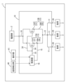
- FIG. 1 is a block diagram of a vehicle equipped with a power supply device according to a first embodiment.
- a power supply device that supplies power based on a power supply unit to a plurality of loads, A plurality of conductive paths connected to a plurality of the loads; a connection portion that connects ends of the conductive paths on the power supply side to each other; A circuit portion having a switch; A control unit that controls the switch, the circuit unit is provided between the connection unit and the power supply unit and is connected to the connection unit; The control unit sets a duty ratio, which is a ratio of an on-time to a switching period, and duty-controls the switch at the set duty ratio to adjust a current supplied to the connection unit; Furthermore, the number of the circuit portions provided is one or more and is less than the number of the conductive paths.
- the power supply device can adjust the current supplied to the connection section in the circuit section and supply it to multiple loads. Moreover, since the number of circuit sections is smaller than the number of conductive paths connected to each load, the number of switches in the circuit sections can also be smaller than the number of conductive paths. Therefore, the power supply device can easily reduce the number of switches in a configuration that supplies power to multiple loads.
- the power supply device can set the duty ratio in stages.
- the power supply device can set the duty ratio in as many stages as there are loads.
- the duty ratio of the first stage is a value adjusted so that a reference value of current flows through the connection portion
- the power supply device according to [3], wherein the duty ratio of an Nth stage from the second stage onwards is a value adjusted so that a current N times the reference value flows through the connection part.
- the power supply device can increase the total current value supplied to multiple loads in proportion to the duty ratio step.
- the circuit unit is provided in plurality, The power supply device according to any one of [1] to [4], wherein the control unit performs duty control by synchronizing the on/off timings of the switches of each of the circuit units.
- the above power supply device makes it easy to prevent current from concentrating in certain circuit sections because the on/off timing of each switch is synchronized.
- a detection unit is provided that detects a voltage value of any one of the plurality of circuit units or a value of a current flowing through any one of the plurality of circuit units, The power supply device according to claim 5, wherein the control unit determines whether or not an overcurrent state exists based on a detection value of the detection unit, and switches all of the switches to an off state when it determines that an overcurrent state exists.
- the power supply device described above can easily reduce the number of detection units because the detection unit used to determine an overcurrent state can be provided in any of the multiple circuit units.
- a power supply device for a vehicle comprising: The power supply device according to any one of [1] to [6], wherein the control unit sets a duty ratio based on at least one of an outside air temperature of the vehicle and a switching operation by an operation unit.
- the power supply device can set the duty ratio to reflect at least one of the vehicle's outside temperature and the switching operation by the operating unit.
- the above power supply device makes it easy to equalize the performance of the switches in each circuit section.
- the power supply device can adjust the current supplied to multiple loads of the same type.
- First Embodiment 1 shows a vehicle 1 equipped with a power supply device 10.
- the vehicle 1 includes a power supply unit 2 and a plurality of (three in this embodiment) loads 3.
- the vehicle 1 supplies power based on the power supply unit 2 to the plurality of loads 3 via the power supply device 10.
- the power supply unit 2 is, for example, a battery.
- the battery is, for example, a lead battery, a lithium ion battery, etc.
- the multiple loads 3 are all heaters.
- the heater includes, for example, a PTC thermistor.
- the load 3 may be something other than a heater, such as a motor, a lamp, or an ECU (Electronic Control Unit).
- the multiple loads 3 may be integrated devices or may not be integrated devices.
- the power supply device 10 is provided between the power supply unit 2 and the multiple loads 3.
- the power supply device 10 supplies power based on the power supply unit 2 to the multiple loads 3.
- the power supply device 10 includes multiple conductive paths 11, a first connection unit 12, a circuit unit 13, a second connection unit 14, a detection unit 15, and a control unit 16.
- the multiple conductive paths 11 are connected to multiple loads 3.
- the number of conductive paths 11 is the same as the number of loads 3 (3 in this embodiment).
- Each conductive path 11 is connected to a different load 3.
- the multiple conductive paths 11 are provided between the power supply unit and the multiple loads 3.
- the multiple conductive paths 11 are provided in parallel with each other.
- An output side terminal 20 is provided at the end of the conductive path 11 opposite the power supply unit 2 side.
- the load 3 is connected to the output side terminal 20.
- the first connection portion 12 corresponds to an example of a "connection portion.”
- the first connection portion 12 connects the ends of the respective conductive paths 11 on the side of the power supply portion 2.
- the respective conductive paths 11 are short-circuited to each other via the first connection portion 12.
- Each load 3 is short-circuited to the first connection portion 12 by being connected to the conductive path 11.
- the circuit unit 13 is provided between the first connection unit 12 and the power supply unit 2.
- the circuit unit 13 is connected to the first connection unit 12.
- the circuit unit 13 has a power path 30 and a switch 31.
- the power path 30 is provided between the first connection unit 12 and the power supply unit 2.
- the power path 30 is connected to the first connection unit 12.
- the switch 31 is provided on the power path 30. When the switch 31 is in an on state, a current based on the power supply unit 2 is supplied to the first connection unit 12 via the switch 31. When the switch 31 is in an off state, the flow of current to the first connection unit 12 via the switch 31 is cut off.
- the switch 31 is configured to include a semiconductor switch.
- the semiconductor switch is a MOSFET (Metal-Oxide-Semiconductor Field Effect Transistor).
- MOSFET Metal-Oxide-Semiconductor Field Effect Transistor
- the configuration including the semiconductor switch is composed only of a semiconductor switch, but it may also be a configuration in which a protection circuit and the like are integrated (for example, an IPD (Intelligent Power Device)).
- the number of circuit parts 13 is one or more and is less than the number of conductive paths 11. In this embodiment, the number of circuit parts 13 is two.
- the multiple circuit parts 13 are arranged in parallel between the power supply unit 2 and the first connection part 12. Each circuit part 13 (more specifically, the power path 30) is connected to the first connection part 12 and short-circuited to each other via the first connection part 12.
- the second connection part 14 connects the ends of the multiple circuit parts 13 (more specifically, the power path 30) on the power supply unit 2 side to each other.
- the switch 31 When the switch 31 is in the on state, the current based on the power supply unit 2 flows into the circuit part 13 (more specifically, the power path 30) via the second connection part 14 and is supplied to the first connection part 12. As a result, the current based on the power supply unit 2 is supplied to the multiple loads 3 via the first connection part 12. All of the multiple switches 31 have the same model number.
- Circuit unit 13 includes circuit units 13A and 13B.
- Circuit unit 13A has a power path 30A and a switch 31A.
- Circuit unit 13B has a power path 30B and a switch 31B.
- Detection unit 15 is, for example, a known voltage detection circuit. Detection unit 15 detects the voltage value of circuit unit 13A. More specifically, detection unit 15 detects the voltage on the first connection unit 12 side of switch 31A in power path 30A. Detection unit 15 outputs a signal that can identify the detection value.
- the control unit 16 is a control circuit such as an integrated circuit.
- the control unit 16 controls the switch 31.
- the control unit 16 sets a duty ratio, which is the ratio of on time to the switching period.
- the control unit 16 duty controls the switch 31 with the set duty ratio to adjust the current supplied to the first connection unit 12.
- the duty control is PWM (Pulse Width Modulation) control, but it may also be duty control with a variable period (for example, PFM (Pulse Frequency Modulation) control).
- the control unit 16 selects and sets one of the multiple duty ratio stages.
- the number of duty ratio stages is the same as the number of conductive paths 11, and the same as the number of loads 3. In other words, in this embodiment, the number of duty ratio stages is three.
- the first stage duty ratio is a value adjusted so that a current of a reference value flows through the first connection part 12.
- the second stage and subsequent N stages of duty ratios are values adjusted so that a current N times the reference value flows through the first connection part 12. For example, if the reference value is 24 A, the first stage duty ratio is a value adjusted so that a current of 24 A flows through the first connection part 12.
- the second stage duty ratio is a value adjusted so that a current twice as large as 24 A (a current of 48 A) flows through the first connection part 12.
- the third stage duty ratio is a value adjusted so that a current three times as large as 24 A (a current of 72 A) flows through the first connection part 12.
- a current N times the reference value includes not only a current strictly N times the reference value, but also a current that is substantially N times the reference value.
- a current that is substantially N times the reference value means “a current that is equal to or greater than the reference value multiplied by (N-0.1) and equal to or less than the reference value multiplied by (N+0.1).”
- a current that is substantially twice the reference value means “a current that is equal to or greater than the reference value multiplied by 1.9 and equal to or less than the reference value multiplied by 2.1.”
- N is an integer equal to or greater than 2.
- the duty ratio is a value greater than 0% and equal to or less than 100%.
- the control unit 16 performs duty control by synchronizing the on/off timing of each switch 31 in each circuit unit 13.
- the power supply device 10 has a common line 33 and multiple branch lines 34. Each branch line 34 branches off from the common line 33 and is connected to the input section (gate) of each switch 31. A signal applied to the common line 33 is applied to the input section (gate) of each switch 31 via each branch line 34.
- the control unit 16 applies a control signal to the common line 33 to synchronize the on/off timing of each switch 31 in each circuit unit 13 and performs duty control.
- the control unit 16 determines whether or not an overcurrent state exists based on the detection value of the detection unit 15.
- the control unit 16 makes the determination based on, for example, the detection value of the detection unit 15 and a threshold value. More specifically, the control unit 16 determines that an overcurrent state exists if the detection value of the detection unit 15 is equal to or less than the threshold value when the switch 31A is in the on state. The control unit 16 determines that an overcurrent state does not exist if the detection value of the detection unit 15 is not equal to or less than the threshold value when the switch 31A is in the on state. If the control unit 16 determines that an overcurrent state exists, it switches all of the switches 31 to the off state.
- the control unit 16 sets the duty ratio based on at least one of the outside air temperature of the vehicle 1 and a switching operation by an operation unit 41 provided in the vehicle 1.
- the control unit 16 can acquire the outside air temperature of the vehicle 1 based on a signal output by a temperature detection unit 40 provided in the vehicle 1.
- the temperature detection unit 40 is, for example, a known temperature sensor. It detects the outside air temperature of the vehicle 1 and outputs a signal that can identify the detected value.
- the control unit 16 may acquire the signal output from the temperature detection unit 40 directly or via another device.
- the operation unit 41 is, for example, an operation member for adjusting the temperature of a heater (load 3).
- the duty ratio that is set is switched by switching the position of the operation member.
- control unit 16 sets a high stage duty ratio when the outside temperature of the vehicle 1 is low. As a result, when the outside temperature of the vehicle 1 is low, the current supplied to the load 3 increases, and the temperature of the heater (load 3) increases. Also, the control unit 16 sets a low stage duty ratio when the outside temperature of the vehicle 1 is high. As a result, when the outside temperature of the vehicle 1 is high, the current supplied to the load 3 decreases, and the temperature of the heater (load 3) decreases.
- the control unit 16 sets a high duty ratio. This increases the current supplied to the load 3, and the temperature of the heater (load 3) increases.
- the control unit 16 sets a low duty ratio. This decreases the current supplied to the load 3, and the temperature of the heater (load 3) decreases.
- the control unit 16 sets the duty ratio when a start condition is satisfied.
- the start condition may be that the start switch of the vehicle 1 is switched to the on state, that a start operation is performed by the user, or other conditions.
- the control unit 16 sets the duty ratio based on, for example, the outside air temperature of the vehicle 1 or the position of an operating member when the start condition is satisfied. Then, the control unit 16 performs duty control of the switch 31 with the set duty ratio.
- the control unit 16 performs duty control for all the switches 31 by synchronizing the on/off timing of the switches 31.
- the control unit 16 determines whether or not an overcurrent state exists during duty control. If the control unit 16 determines that an overcurrent state exists, it stops duty control and switches all switches 31 to the off state.
- the control unit 16 also determines whether or not a termination condition is met during duty control.
- the termination condition may be that the start switch of the vehicle 1 is switched to the OFF state, that a termination operation is performed by the user, or other conditions.
- the control unit 16 ends the duty control and switches all switches 31 to the OFF state.
- the power supply device 10 can adjust the current supplied to the first connection portion 12 by the circuit unit 13 and supply the current to the multiple loads 3. Moreover, since the number of circuit units 13 is smaller than the number of conductive paths 11 connected to each load 3, the number of switches 31 included in the circuit units 13 can also be smaller than the number of conductive paths 11. Therefore, the power supply device 10 can easily reduce the number of switches 31 in a configuration in which power is supplied to the multiple loads 3.
- the power supply device 10 can set the duty ratio in stages.
- the power supply device 10 can set the duty ratio in as many stages as there are loads 3.
- the power supply device 10 can increase the total current value supplied to the multiple loads 3 in proportion to the stages of the duty ratio.
- the power supply device 10 makes it easy to prevent current from concentrating in some circuit sections 13 because the on/off timing of each switch 31 is synchronized.
- the power supply device 10 only needs to provide the detection unit 15 used to determine an overcurrent state in the circuit unit 13A out of the multiple circuit units 13, making it easy to reduce the number of detection units 15.
- the power supply device 10 can set the duty ratio by reflecting at least one of the outside temperature of the vehicle 1 and the switching operation by the operation unit 41.
- the power supply device 10 makes it easy to standardize the performance of the switches 31 in each circuit section 13.
- the power supply device 10 can adjust the current supplied to multiple loads 3 of the same type.
- the number of duty cycle stages does not have to be the same as the number of conductive paths, nor does it have to be the same as the number of loads.
- the on/off timing of each switch does not have to be synchronized.
- the detection unit detects the voltage value of the circuit unit, but it may also be configured to detect the current flowing through the circuit unit.
- the detection unit may be, for example, a known current sensor.
- the control unit may determine that an overcurrent state has occurred when the detection value (the value of the current flowing through the circuit unit) exceeds a threshold current.
Landscapes
- Engineering & Computer Science (AREA)
- Mechanical Engineering (AREA)
- Direct Current Feeding And Distribution (AREA)
- Charge And Discharge Circuits For Batteries Or The Like (AREA)
Abstract
Description
電源部に基づく電力を複数の負荷に供給する電力供給装置であって、
複数の前記負荷に接続される複数の導電路と、
各々の前記導電路における前記電源部側の端部同士を接続する接続部と、
スイッチを有する回路部と、
前記スイッチを制御する制御部と、を備え、
前記回路部は、前記接続部と前記電源部との間に設けられ、前記接続部に接続され、
前記制御部は、スイッチング周期に対するオン時間の割合であるデューティ比を設定し、設定したデューティ比で前記スイッチをデューティ制御して前記接続部に供給される電流を調整し、
更に、前記回路部は、1以上で、且つ前記導電路よりも少ない数設けられる。
複数の前記負荷に接続される複数の導電路と、
各々の前記導電路における前記電源部側の端部同士を接続する接続部と、
スイッチを有する回路部と、
前記スイッチを制御する制御部と、を備え、
前記回路部は、前記接続部と前記電源部との間に設けられ、前記接続部に接続され、
前記制御部は、スイッチング周期に対するオン時間の割合であるデューティ比を設定し、設定したデューティ比で前記スイッチをデューティ制御して前記接続部に供給される電流を調整し、
更に、前記回路部は、1以上で、且つ前記導電路よりも少ない数設けられる
電力供給装置。
〔1〕に記載の電力供給装置。
〔2〕に記載の電力供給装置。
2段階目以降のN段階目のデューティ比は、前記接続部に前記基準値をN倍した電流が流れるように調整する値である
〔3〕に記載の電力供給装置。
前記制御部は、各々の前記回路部が有する各々の前記スイッチのオンオフ時期を同期させてデューティ制御する
〔1〕から〔4〕のいずれかに記載の電力供給装置。
前記制御部は、前記検出部の検出値に基づいて過電流状態であるか否かを判定し、前記過電流状態であると判定した場合に全ての前記スイッチをオフ状態に切り替える
〔5〕に記載の電力供給装置。
前記制御部は、車両の外気温、及び操作部による切替操作の少なくとも一方に基づいてデューティ比を設定する
〔1〕から〔6〕のいずれかに記載の電力供給装置。
〔1〕から〔7〕のいずれかに記載の電力供給装置。
〔1〕から〔8〕のいずれかに記載の電力供給装置。
図1には、電力供給装置10を備えた車両1が示されている。車両1は、電源部2と、複数(本実施形態では3)の負荷3と、を備える。車両1は、電力供給装置10を介して、電源部2に基づく電力を複数の負荷3に供給する。
制御部16は、開始条件が成立した場合に、デューティ比を設定する。開始条件は、車両1の始動スイッチがオン状態に切り替わったことであってもよいし、ユーザによって開始操作が行われたことであってもよいし、その他の条件であってもよい。制御部16は、例えば開始条件が成立したときの車両1の外気温、又は操作部材の位置に基づいてデューティ比を設定する。そして、制御部16は、設定したデューティ比でスイッチ31をデューティ制御する。制御部16は、全てのスイッチ31に対し、スイッチ31のオンオフ時期を同期させてデューティ制御する。
電力供給装置10は、第1接続部12に供給される電流を回路部13で調整して複数の負荷3に供給することができる。しかも、回路部13の数は、各々の負荷3に接続される導電路11の数よりも少ないため、回路部13が有するスイッチ31の数も導電路11の数よりも少なくすることができる。したがって、電力供給装置10は、複数の負荷3に電力を供給する構成においてスイッチ31の数の低減を図りやすい。
本開示は、上記記述及び図面によって説明した実施形態に限定されるものではない。例えば、上述又は後述の実施形態の特徴は、矛盾しない範囲であらゆる組み合わせが可能である。また、上述又は後述の実施形態のいずれの特徴も、必須のものとして明示されていなければ省略することもできる。更に、上述した実施形態は、次のように変更されてもよい。
2…電源部
3…負荷
10…電力供給装置
11…導電路
12…第1接続部(接続部)
13…回路部
13A…回路部
13B…回路部
14…第2接続部
15…検出部
16…制御部
20…出力側端子
30…電力路
30A…電力路
30B…電力路
31…スイッチ
31A…スイッチ
31B…スイッチ
33…共通線
34…分岐線
40…温度検出部
41…操作部
Claims (9)
- 電源部に基づく電力を複数の負荷に供給する電力供給装置であって、
複数の前記負荷に接続される複数の導電路と、
各々の前記導電路における前記電源部側の端部同士を接続する接続部と、
スイッチを有する回路部と、
前記スイッチを制御する制御部と、を備え、
前記回路部は、前記接続部と前記電源部との間に設けられ、前記接続部に接続され、
前記制御部は、スイッチング周期に対するオン時間の割合であるデューティ比を設定し、設定したデューティ比で前記スイッチをデューティ制御して前記接続部に供給される電流を調整し、
更に、前記回路部は、1以上で、且つ前記導電路よりも少ない数設けられる
電力供給装置。 - 前記制御部は、複数段階のデューティ比のうちいずれかのデューティ比を選択して設定する
請求項1に記載の電力供給装置。 - デューティ比の段階数は、前記導電路の数と同じである
請求項2に記載の電力供給装置。 - 1段階目のデューティ比は、前記接続部に基準値の電流が流れるように調整する値であり、
2段階目以降のN段階目のデューティ比は、前記接続部に前記基準値をN倍した電流が流れるように調整する値である
請求項3に記載の電力供給装置。 - 前記回路部は複数設けられ、
前記制御部は、各々の前記回路部が有する各々の前記スイッチのオンオフ時期を同期させてデューティ制御する
請求項1から請求項4のいずれか一項に記載の電力供給装置。 - 複数の前記回路部のいずれかの電圧値、又は複数の前記回路部のいずれかを流れる電流の値を検出する検出部を備え、
前記制御部は、前記検出部の検出値に基づいて過電流状態であるか否かを判定し、前記過電流状態であると判定した場合に全ての前記スイッチをオフ状態に切り替える
請求項5に記載の電力供給装置。 - 車両用の電力供給装置であって、
前記制御部は、車両の外気温、及び操作部による切替操作の少なくとも一方に基づいてデューティ比を設定する
請求項1から請求項4のいずれか一項に記載の電力供給装置。 - 複数の前記スイッチは、全て同じ型番である
請求項1から請求項4のいずれか一項に記載の電力供給装置。 - 複数の前記負荷は、ヒータ、モータ、ランプ、及びECUのいずれか一種である
請求項1から請求項4のいずれか一項に記載の電力供給装置。
Priority Applications (2)
| Application Number | Priority Date | Filing Date | Title |
|---|---|---|---|
| DE112023004062.1T DE112023004062T5 (de) | 2022-09-29 | 2023-08-21 | Leistungsversorgungsvorrichtung |
| CN202380066185.3A CN119895685A (zh) | 2022-09-29 | 2023-08-21 | 电力供给装置 |
Applications Claiming Priority (2)
| Application Number | Priority Date | Filing Date | Title |
|---|---|---|---|
| JP2022156350A JP2024049864A (ja) | 2022-09-29 | 2022-09-29 | 電力供給装置 |
| JP2022-156350 | 2022-09-29 |
Publications (1)
| Publication Number | Publication Date |
|---|---|
| WO2024070332A1 true WO2024070332A1 (ja) | 2024-04-04 |
Family
ID=90477201
Family Applications (1)
| Application Number | Title | Priority Date | Filing Date |
|---|---|---|---|
| PCT/JP2023/030047 Ceased WO2024070332A1 (ja) | 2022-09-29 | 2023-08-21 | 電力供給装置 |
Country Status (4)
| Country | Link |
|---|---|
| JP (2) | JP2024049864A (ja) |
| CN (1) | CN119895685A (ja) |
| DE (1) | DE112023004062T5 (ja) |
| WO (1) | WO2024070332A1 (ja) |
Citations (4)
| Publication number | Priority date | Publication date | Assignee | Title |
|---|---|---|---|---|
| JP2007215257A (ja) * | 2006-02-07 | 2007-08-23 | Nagasaki Univ | 分散型電源配電システムおよび分散型電源装置 |
| JP2017188772A (ja) * | 2016-04-05 | 2017-10-12 | 株式会社オートネットワーク技術研究所 | 給電制御装置 |
| JP2019047582A (ja) * | 2017-08-31 | 2019-03-22 | 株式会社オートネットワーク技術研究所 | 車載用の電力制御装置及び車載用の電力制御システム |
| JP2021045018A (ja) * | 2019-09-13 | 2021-03-18 | 矢崎総業株式会社 | 車載電源装置 |
Family Cites Families (3)
| Publication number | Priority date | Publication date | Assignee | Title |
|---|---|---|---|---|
| JP5109920B2 (ja) * | 2008-10-14 | 2012-12-26 | トヨタ自動車株式会社 | スイッチング電源装置 |
| JP2011213321A (ja) * | 2010-04-02 | 2011-10-27 | Autonetworks Technologies Ltd | 車両用電源供給装置、および、車両用制御装置 |
| JP2013091392A (ja) * | 2011-10-25 | 2013-05-16 | Daihatsu Motor Co Ltd | 電気負荷制御装置 |
-
2022
- 2022-09-29 JP JP2022156350A patent/JP2024049864A/ja active Pending
-
2023
- 2023-08-21 DE DE112023004062.1T patent/DE112023004062T5/de active Pending
- 2023-08-21 WO PCT/JP2023/030047 patent/WO2024070332A1/ja not_active Ceased
- 2023-08-21 CN CN202380066185.3A patent/CN119895685A/zh active Pending
-
2026
- 2026-02-04 JP JP2026016957A patent/JP2026063534A/ja active Pending
Patent Citations (4)
| Publication number | Priority date | Publication date | Assignee | Title |
|---|---|---|---|---|
| JP2007215257A (ja) * | 2006-02-07 | 2007-08-23 | Nagasaki Univ | 分散型電源配電システムおよび分散型電源装置 |
| JP2017188772A (ja) * | 2016-04-05 | 2017-10-12 | 株式会社オートネットワーク技術研究所 | 給電制御装置 |
| JP2019047582A (ja) * | 2017-08-31 | 2019-03-22 | 株式会社オートネットワーク技術研究所 | 車載用の電力制御装置及び車載用の電力制御システム |
| JP2021045018A (ja) * | 2019-09-13 | 2021-03-18 | 矢崎総業株式会社 | 車載電源装置 |
Also Published As
| Publication number | Publication date |
|---|---|
| JP2026063534A (ja) | 2026-04-10 |
| JP2024049864A (ja) | 2024-04-10 |
| DE112023004062T5 (de) | 2025-07-10 |
| CN119895685A (zh) | 2025-04-25 |
Similar Documents
| Publication | Publication Date | Title |
|---|---|---|
| JP5170248B2 (ja) | 電源制御回路、電源装置、電源システムおよび電源制御装置の制御方法 | |
| US8947064B2 (en) | System and method for driving an electronic switch dependent on temperature | |
| US8598859B2 (en) | Power supply controller | |
| JP6288379B2 (ja) | 突入電流防止回路 | |
| CN1719730B (zh) | 半导体开关控制装置 | |
| KR20150007980A (ko) | 여러 스위치를 이용한 돌입 제어 | |
| US8299766B2 (en) | Switching output circuit | |
| US20080074820A1 (en) | Current protection circuit for intelligent power switch | |
| US20140091853A1 (en) | Switching circuit | |
| US20080048630A1 (en) | Switching power supply circuit | |
| JP2017212805A (ja) | 車両用電圧変換装置 | |
| JP5724397B2 (ja) | スイッチング素子の駆動回路 | |
| JPH03256407A (ja) | 制御回路 | |
| KR20180071114A (ko) | 프리차지 이중화 회로 | |
| JP5673634B2 (ja) | 駆動対象スイッチング素子の駆動回路 | |
| CN111464029A (zh) | 用于dc-dc转换器的电流感测控制器 | |
| KR950002233A (ko) | 노이즈를 감소하는 출력단을 구비한 집적회로 | |
| WO2024070332A1 (ja) | 電力供給装置 | |
| JP2002270336A (ja) | Ptcヒータ制御装置 | |
| JP2018196115A (ja) | 電子モジュールおよび自動車ならびにモジュールのスイッチオン過程中の入力電流を制限する方法 | |
| KR20100014890A (ko) | 적어도 하나의 led를 동작시키기 위한 led 모듈 및 방법 | |
| JP3793027B2 (ja) | 負荷駆動回路 | |
| JP6322123B2 (ja) | 電流制限回路 | |
| KR20020016398A (ko) | 엘시디 백라이트 인버터의 과전압 보호회로 | |
| JP7303903B2 (ja) | 電動モータの駆動装置 |
Legal Events
| Date | Code | Title | Description |
|---|---|---|---|
| 121 | Ep: the epo has been informed by wipo that ep was designated in this application |
Ref document number: 23871573 Country of ref document: EP Kind code of ref document: A1 |
|
| WWE | Wipo information: entry into national phase |
Ref document number: 202380066185.3 Country of ref document: CN |
|
| WWP | Wipo information: published in national office |
Ref document number: 202380066185.3 Country of ref document: CN |
|
| WWE | Wipo information: entry into national phase |
Ref document number: 112023004062 Country of ref document: DE |
|
| WWP | Wipo information: published in national office |
Ref document number: 112023004062 Country of ref document: DE |
|
| 122 | Ep: pct application non-entry in european phase |
Ref document number: 23871573 Country of ref document: EP Kind code of ref document: A1 |