WO2024069797A1 - エレベーターシステム、中継装置、第二中継装置、中継方法、及びコンピュータ読み取り可能な記録媒体 - Google Patents
エレベーターシステム、中継装置、第二中継装置、中継方法、及びコンピュータ読み取り可能な記録媒体 Download PDFInfo
- Publication number
- WO2024069797A1 WO2024069797A1 PCT/JP2022/036180 JP2022036180W WO2024069797A1 WO 2024069797 A1 WO2024069797 A1 WO 2024069797A1 JP 2022036180 W JP2022036180 W JP 2022036180W WO 2024069797 A1 WO2024069797 A1 WO 2024069797A1
- Authority
- WO
- WIPO (PCT)
- Prior art keywords
- car
- elevator
- robot
- information
- relay device
- Prior art date
Links
- 238000000034 method Methods 0.000 title claims description 45
- 230000005540 biological transmission Effects 0.000 claims description 32
- 230000002265 prevention Effects 0.000 claims description 7
- 238000005286 illumination Methods 0.000 claims description 6
- SAZUGELZHZOXHB-UHFFFAOYSA-N acecarbromal Chemical compound CCC(Br)(CC)C(=O)NC(=O)NC(C)=O SAZUGELZHZOXHB-UHFFFAOYSA-N 0.000 claims description 3
- 230000006978 adaptation Effects 0.000 abstract 1
- 230000006870 function Effects 0.000 description 64
- 230000008569 process Effects 0.000 description 38
- 238000010586 diagram Methods 0.000 description 16
- 230000000694 effects Effects 0.000 description 11
- 238000004891 communication Methods 0.000 description 4
- 238000005516 engineering process Methods 0.000 description 3
- 230000008901 benefit Effects 0.000 description 2
- 230000007257 malfunction Effects 0.000 description 2
- 230000004048 modification Effects 0.000 description 2
- 230000032258 transport Effects 0.000 description 2
- 239000002131 composite material Substances 0.000 description 1
- 230000004044 response Effects 0.000 description 1
- 239000004065 semiconductor Substances 0.000 description 1
Images


Classifications
-
- B—PERFORMING OPERATIONS; TRANSPORTING
- B66—HOISTING; LIFTING; HAULING
- B66B—ELEVATORS; ESCALATORS OR MOVING WALKWAYS
- B66B1/00—Control systems of elevators in general
- B66B1/02—Control systems without regulation, i.e. without retroactive action
- B66B1/06—Control systems without regulation, i.e. without retroactive action electric
- B66B1/14—Control systems without regulation, i.e. without retroactive action electric with devices, e.g. push-buttons, for indirect control of movements
- B66B1/18—Control systems without regulation, i.e. without retroactive action electric with devices, e.g. push-buttons, for indirect control of movements with means for storing pulses controlling the movements of several cars or cages
-
- B—PERFORMING OPERATIONS; TRANSPORTING
- B66—HOISTING; LIFTING; HAULING
- B66B—ELEVATORS; ESCALATORS OR MOVING WALKWAYS
- B66B17/00—Hoistway equipment
- B66B17/14—Applications of loading and unloading equipment
- B66B17/16—Applications of loading and unloading equipment for loading and unloading mining-hoist cars or cages
- B66B17/20—Applications of loading and unloading equipment for loading and unloading mining-hoist cars or cages by moving vehicles into, or out of, the cars or cages
Definitions
- the present disclosure relates to an elevator system, a relay device, a second relay device, a relay method, and a computer-readable recording medium.
- Patent Document 1 discloses a technology in which an automated guided vehicle moves between floors using a button pressing assist unit that is detachably attached to an elevator operation panel.
- the automated guided vehicle of this technology is equipped with a communication unit that communicates with a button pressing assist unit that is installed later.
- the automated guided vehicle sends a signal to press an up floor button at the elevator hall, the up floor button is pressed by the button pressing assist unit.
- the button pressing assist unit also detects when the button goes from lit to off, and transmits that signal to the automated guided vehicle.
- Patent Document 1 it is necessary to realize the robot's boarding and disembarking using only the information obtained from the elevator operation panel and the functions that can be executed from the elevator operation panel. In order to enable the robot to cooperate with the elevator in a highly efficient manner under such constraints, a great deal of human effort is required for modernizing the elevator or modifying the software, etc.
- This disclosure has been made to solve the problems described above, and aims to reduce the burden on those involved in modernization or software modifications when providing an elevator system that enables the robot to board and disembark through cooperation between the elevator and the robot.
- the elevator system of the present disclosure comprises a plurality of first relay devices, each of which corresponds to one of a plurality of elevator cars installed in a facility and is connected to each other so as to receive elevator information obtained from the car operating panel of the corresponding car and transmit executable commands from the car operating panel to each machine control device, and a second relay device, which is connected to each of the plurality of first relay devices so as to be able to communicate with each of the plurality of first relay devices.
- the second relay device comprises a second receiving unit that receives a usage request including call information from the boarding floor to the destination floor of a robot moving through the facility, and a second transmitting unit that transmits a robot call registration request to a first relay device among the plurality of first relay devices that corresponds to an assigned car to which the robot call included in the usage request is to be assigned.
- Each of the plurality of first relay devices comprises a first receiving unit that receives the robot call registration request transmitted by the second transmitting unit, and a first transmitting unit that transmits the robot call registration request received by the first receiving unit to each machine control device.
- the second relay device of the present disclosure corresponds to one of multiple elevator cars installed in the facility, receives elevator information obtained from the car operation panel of the corresponding car, and is connected so as to be able to communicate with each of the multiple first relay devices to which it is connected so as to be able to transmit executable commands from the car operation panel to each machine control device.
- the second relay device includes a second receiving unit that receives a usage request including call information from the boarding floor to the destination floor of a robot moving through the facility, and a second transmitting unit that transmits a robot call registration request to the first relay device to be transmitted to each machine control device to the first relay device corresponding to an assigned car to which the robot call included in the usage request is assigned among the multiple first relay devices.
- the relay device disclosed herein is connected so as to receive elevator information obtained from each car operating panel of multiple elevator cars installed in the facility, and transmit executable commands from the car operating panel to each machine control device corresponding to each of the multiple cars.
- the relay device includes a receiving unit that receives a usage request including call information from the boarding floor to the destination floor of a robot moving through the facility, and a transmitting unit that transmits a robot call registration request to each machine control device corresponding to an assigned car that is to be assigned the robot call included in the usage request, among the multiple cars.
- the relay method disclosed herein receives elevator information obtained from each car operating panel of multiple elevator cars installed in a facility, and transmits executable commands from the car operating panel to each machine control device corresponding to each of the multiple cars.
- the relay method includes a step of receiving a usage request including call information from the boarding floor to the destination floor of a robot moving through the facility, a step of determining an assigned car to which the robot call included in the usage request is assigned based on the elevator information, and a step of transmitting a registration request for the robot call to each machine control device corresponding to the assigned car.
- the computer-readable recording medium of the present disclosure records a relay program that causes a computer to receive elevator information obtained from each car operating panel of multiple elevator cars installed in a facility and transmit executable commands from the car operating panel to each machine control device corresponding to each of the multiple cars.
- the relay program is configured to cause a computer to receive a usage request including call information from the boarding floor to the destination floor of a robot moving through the facility, determine an assigned car to which the robot call included in the usage request is assigned based on the elevator information, and transmit a registration request for the robot call to each machine control device corresponding to the assigned car.
- This disclosure provides an elevator system that allows the robot to board and disembark through cooperation between the elevator and the robot, thereby reducing the burden on those involved in modernization or software modification.
- FIG. 1 is a configuration diagram of a building system according to a first embodiment.
- 1 is a block diagram showing the functions of an elevator system according to a first embodiment.
- FIG. 4 is a flowchart showing an operation example of the elevator system according to the first embodiment. 4 illustrates an example of selection of an assigned car by the second relay device according to the first embodiment.
- FIG. 2 is a hardware configuration diagram of a main part of the elevator system according to the first embodiment.
- FIG. 11 is a block diagram showing the functions of an elevator system according to a second embodiment. 10 is a flowchart showing an example of the operation of the elevator system according to the second embodiment.
- FIG. 11 is a block diagram showing the functions of an elevator system according to a third embodiment.
- FIG. 13 shows an example of selection of an evacuation floor by an evacuation floor selection unit.
- 13 is a flowchart showing an example of the operation of the elevator system according to the third embodiment.
- FIG. 13 is a block diagram showing the functions of an elevator system according to a fourth embodiment.
- 13 is a flowchart showing an example of the operation of the elevator system according to the fourth embodiment.
- FIG. 13 is a configuration diagram of a building system according to a fifth embodiment. A block diagram showing the functions of an elevator system according to embodiment 5.
- FIG. 1 is a configuration diagram of a building system according to a first embodiment.
- the building system is applied to a facility.
- the facility may be, for example, an indoor facility, an outdoor facility, or a facility that combines these.
- the facility may consist of, for example, one or more buildings.
- the facility may be, for example, a part of a building.
- the building system applied to a facility includes a robot 1 that moves around the facility. In this example, the robot 1 operates based on the control of a robot server 2.
- the robot 1 communicates with the robot server 2 wirelessly.
- a management room 3 is provided in the facility.
- the management room 3 is a place where a facility manager or the like manages the facility.
- the robot server 2 is provided, for example, in the management room 3.
- the building system includes an elevator system as an internal system.
- the elevator system includes an elevator.
- An elevator shaft 4 is provided in the facility.
- the shaft 4 is a space that spans multiple floors with its longitudinal direction in the vertical direction.
- An elevator machine room 5 is provided above the shaft 4.
- a landing 6 is provided on each floor in the facility. The landing 6 is a place that leads to the shaft 4.
- the elevator comprises a plurality of units and a group control device 7.
- Each unit comprises a hoist 8, a deflector sheave 9, a main rope 10, a car 11, a counterweight 12, and an individual car control device 13.
- the group control device 7, and the hoist 8, deflector sheave 9, and individual car control device 13 of each unit are provided in the machine room 5.
- the car 11 and the counterweight 12 are provided in the hoistway 4.
- the hoist 8 includes a motor that generates a driving force, and a sheave that rotates by the driving force generated by the motor.
- the main rope 10 is wound around the sheave and the deflector sheave 9 of the hoist 8.
- the main rope 10 supports the load of the car 11 on one side of the sheave of the hoist 8.
- the main rope 10 supports the load of the counterweight 12 on the other side of the sheave of the hoist 8.
- the car 11 and counterweight 12 run on opposite sides of the elevator shaft in the vertical direction via the sheaves and main ropes 10 of the elevator shaft 8, driven by the driving force generated by the motor of the elevator shaft 8.
- the car 11 travels through the elevator shaft 4 to transport users or robots inside the car 11 between multiple floors of the facility.
- the car controller 13 of each unit corresponds to a car 11 of the same unit. Each car controller 13 is electrically connected to the hoist 8 of the same unit. Each car controller 13 is connected to the corresponding car 11 through a car transmission cable 16. Each car controller 13 controls the running of the car 11 through control of the hoist 8. Each car controller 13 of each unit is electrically connected to the group management device 7 through a transmission cable 14.
- the group management device 7 accepts information on user hall calls received by a hall operating panel (not shown) installed at the elevator hall 6.
- the group management device 7 assigns the hall calls to one of the cars 11.
- the car 11 is equipped with a car operation panel 15.
- the car operation panel 15 is an elevator operation panel that accepts car call operations by elevator users. Car call information accepted by the car operation panel 15 of the car 11 is transmitted to the car control device 13 corresponding to the car 11 via the car transmission cable 16.
- the elevator system includes a plurality of first relay devices 30 and a second relay device 40.
- the first relay devices 30 are, for example, protocol converters. Each of the first relay devices 30 corresponds to one of the units.
- the first relay devices 30 are electrically connected to each machine control device 13 of the corresponding unit via a relay cable 17.
- the relay cable 17 connected to the first relay devices 30 is electrically connected to a car transmission cable 16 that connects each machine control device 13 and the car 11 in the unit to which the first relay device 30 corresponds.
- Each of the first relay devices 30 is provided in a machine room 5.
- the second relay device 40 is a separate device from the group management device 7.
- the second relay device 40 is provided in the management room 3.
- the second relay device 40 is electrically connected to the robot server 2 via a cable 18.
- the second relay device 40 may be connected to the robot server 2 wirelessly.
- the second relay device 40 is electrically connected to each of the first relay devices 30 via an elevator transmission cable 19.
- the second relay device 40 is connected to each machine control device 13 via the first relay device 30 for each unit. That is, each first relay device 30 is interposed between the corresponding machine control device 13 and the second relay device 40.
- the second relay device 40 executes each function by reading a relay program recorded on a computer-readable recording medium and operating according to the relay program.
- the recording medium on which the relay program is recorded may be, for example, one that is built into the second relay device 40 or one that is connected to the second relay device 40.
- the relay program may be installed in the second relay device 40 via a communication network such as the Internet, or may be installed in the second relay device 40 by reading it from an external portable recording medium on which the relay program is recorded.
- the robot 1 uses an elevator to access multiple floors of a facility.
- a request for use including call information is transmitted.
- the request for use is transmitted, for example, from the robot server 2 that controls the robot 1.
- the request for use may be transmitted from the robot 1.
- the call information for the robot 1 includes information on the boarding floor and destination floor of the robot 1.
- the request for use is transmitted to the second relay device 40.
- the second relay device 40 performs a process of allocating the call for the robot 1 to one of the cars 11.
- the allocation of the robot 1's call is performed, for example, based on elevator information.
- the elevator information is sent, for example, from each of the first relay devices 30 to the second relay device 40.
- the group management device 7 does not perform the process of allocating the robot 1's call to any of the cars 11.
- the second relay device 40 sends a registration request including information on the call to the first relay device 30 corresponding to the car 11 to which the robot 1's call has been allocated.
- the second relay device 40 sends information identifying the car 11 to which the robot 1's call has been allocated to the robot server 2 that controls that robot 1.
- the second relay device 40 transmits information about the call as a car call for that car 11 to the individual car control device 13 that controls that car 11.
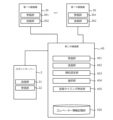
- FIG. 2 is a block diagram showing the functions of the elevator system according to the first embodiment.
- the robot server 2 includes a transmission unit 21 and a reception unit 22.
- the second relay device 40 includes a reception unit 401 as a second reception unit, a transmission unit 402 as a second transmission unit, a ranking setting unit 403, a selection unit 404, a transmission timing determination unit 405, and an elevator information storage unit 420.
- Each first relay device 30 includes a reception unit 301 as a first reception unit, and a transmission unit 302 as a first transmission unit.
- the transmitting unit 21 of the robot server 2 has a function to transmit a usage request including information on the call of the robot 1 to the receiving unit 401 of the second relay device 40, and a function to transmit a robot operation stop signal and a robot operation return signal to the receiving unit 401 of the second relay device 40.
- Robot operation here refers to elevator operation in response to a call of the robot 1.
- the robot operation stop signal is a signal requesting that robot operation be stopped due to a factor on the robot side, such as a malfunction of the robot 1.
- the robot operation return signal is a signal requesting that robot operation be resumed while robot operation is stopped.
- the receiving unit 22 of the robot server 2 has a function to receive, from the transmitting unit 402 of the second relay device 40, assigned car information that specifies the car 11 to which the call of the robot 1 is assigned.
- the receiving unit 401 of the second relay device 40 has a function to receive a request for use and a robot operation stop signal from the transmitting unit 21 of the robot server 2, and a function to receive elevator information from the transmitting unit 302 of the first relay device 30.
- the elevator information storage unit 420 has the function of storing elevator information.
- the elevator information includes information obtained from the car operation panel 15 of each unit.
- the elevator information for each unit includes car position information of the car 11, car travel direction information, door open button light illumination information, in-car destination floor button illumination information, and in-car destination floor button registration availability information.
- the ranking setting unit 403 has a function of setting the ranking of some or all of the multiple cars 11 as candidate cars to which a call from the robot 1 is to be assigned.
- the ranking setting unit 403 sets the ranking of each car 11 based on the elevator information stored in the elevator information storage unit 420.
- the selection unit 404 has a function of selecting an assigned car to which the call of the robot 1 is to be assigned from among the candidate cars whose ranks have been set by the rank setting unit 403.
- the selection unit 404 selects an assigned car based on the ranks set by the rank setting unit 403. For example, the selection unit 404 selects the candidate car whose rank has been set as the number 1 assigned car.
- the transmission timing determination unit 405 has a function of determining the timing to transmit a boarding floor car call to the assigned car selected by the selection unit 404 based on the elevator information stored in the elevator information storage unit 420.
- the transmission timing determination unit 405 determines, for example, the timing when the boarding floor and the destination floor are located in this order ahead of the car 11 in the running direction as the timing to transmit the boarding floor car call.
- the transmission unit 402 of the second relay device 40 has a function of transmitting a registration request for a boarding floor car call to the assigned car selected by the selection unit 404 and a registration request for a destination floor car call to the assigned car to the receiving unit 301 of the first relay device 30.
- the transmission unit 402 of the second relay device 40 has a function of transmitting information identifying the assigned car selected by the selection unit 404 to the receiving unit 22 of the robot server 2.
- the receiving unit 301 of the first relay device 30 has a function of receiving a call registration request and the like from the transmitting unit 402 of the second relay device 40.
- the receiving unit 301 of the first relay device 30 has a function of receiving elevator information from each unit control device 13 of the corresponding unit every time the elevator information for that unit changes.
- the transmitting unit 302 of the first relay device 30 has a function of transmitting the call registration request transmitted by the transmitting unit 402 of the second relay device 40 as a car call for the car 11 of the corresponding unit to the individual car control device 13 that controls the car 11.
- the transmitting unit 302 of the first relay device 30 has a function of transmitting elevator information to the receiving unit 401 of the second relay device 40 every time the elevator information for the corresponding unit changes.
- FIG. 3 is a flowchart showing an operation example of the elevator system according to the first embodiment. Here, a series of operations until the elevator system registers a boarding floor car call of the robot 1 will be described. This flowchart also shows a part of a relay method according to the embodiment of the present disclosure.
- step S100 the second relay device 40 judges whether the receiving unit 401 has received a usage request including information about a call to the robot 1 from the transmitting unit 21 of the robot server 2. If the judgment is found to be true, the process proceeds to step S102, and if the judgment is found to be false, the process returns to step S100.
- step S102 the ranking setting unit 403 sets the rankings of the multiple cars 11 as candidate cars based on the information stored in the elevator information storage unit 420. After the processing of step S102 is performed, the process proceeds to step S104.
- step S104 the selection unit 404 selects the candidate car that has been ranked first by the ranking setting unit 403 as the car to be assigned. After the processing of step S104 is performed, the processing proceeds to step S106.
- step S106 the transmission timing determination unit 405 determines, based on the elevator information, whether the condition that the boarding floor and the destination floor are located in that order ahead in the direction of travel of the assigned car is met. If the result shows that the condition is not met, the process returns to step S106, and if the condition is met, the process proceeds to step S108.
- step S108 the transmission unit 402 transmits a registration request for a boarding floor car call for the assigned car selected by the selection unit 404 to the reception unit 301 of the first relay device 30 corresponding to the assigned car.
- the transmission unit 402 also transmits assigned car information that identifies the assigned car selected by the selection unit 404 to the reception unit 22 of the robot server 2. Thereafter, the processing of the second relay device 40 ends.
- FIG. 4 shows an example of the selection of an assigned car by the second relay device 40 according to the first embodiment.
- the elevator has eight units, A to H.
- the request to use the robot 1 is sent to the second relay device 40 via the robot server 2 or the like when the robot 1 moves from the boarding floor to the destination floor.
- the ranking setting unit 403 acquires the elevator status for each unit based on the elevator information.
- the elevator status for each unit includes security restricted floor determination information, car position/travel direction information, and information on the distance from the boarding floor of the robot 1 to the car 11.
- the security restricted floor determination information is information that identifies a security restricted floor where boarding and alighting are restricted from a security standpoint.
- the car position/travel direction information is information that indicates whether the boarding floor and the destination floor are located in that order ahead of the travel direction of the car 11.
- a priority is set for the use of these pieces of information.
- the order of the security restricted floor determination information, car position/travel direction information, and information on the distance from the boarding floor of the robot 1 to the car 11 is from highest to lowest priority.
- the priority setting unit 403 first performs a determination process based on the security restricted floor determination information, which has the highest priority.
- the priority setting unit 403 determines whether the boarding floor or the destination floor is a security restricted floor based on the in-car destination floor button registration availability information stored in the elevator information storage unit 420.
- some elevator systems are set up to disable call registration for rear floors, which are floors located on the opposite side of the car's travel direction. In such elevator systems, the rear floors are included in the floors that cannot be registered in the in-car destination floor button registration availability information, and there is a possibility that the security restricted floors cannot be accurately identified.
- the ranking setting unit 403 reads out the in-cabin destination floor button registration availability information acquired when cage 11 most recently stopped in a non-directional manner. Then, the ranking setting unit 403 determines whether the boarding floor or destination floor of robot 1 is included in the security restricted floors that cannot be registered in the read in-cabin destination floor button registration availability information. Then, the ranking setting unit 403 excludes cages 11 of cars whose boarding floors or destination floors are included in security restricted floors from the candidate cages. In the example shown in FIG.
- the ranking setting unit 403 provisionally sets cages A to D, whose boarding floors and destination floors are service floors, to be tied for first place, and excludes cages E to H, whose boarding floors or destination floors are security restricted floors, from the candidate cages.
- the ranking setting unit 403 may, for example, omit subsequent ranking setting processing for a cage 11 that has been excluded from the candidate cages.
- the ranking setting unit 403 performs a judgment process based on the cage position/travel direction information with the next highest priority.
- the ranking setting unit 403 judges whether the boarding floor and destination floor of the robot 1 are located ahead of the cage 11 in this order in the traveling direction.
- the ranking setting unit 403 provisionally sets cars A and B, whose boarding floor and destination floor are located ahead of the cage 11 in this order in the traveling direction, to a tie for first place, and provisionally sets cars C and D, whose boarding floor and destination floor are not located ahead of the cage 11 in this order in the traveling direction, to a tie for third place.
- the ranking setting unit 403 performs a determination process based on the distance from the boarding floor, which has the next highest priority.
- the ranking setting unit 403 sets the car 11, which is closer to the boarding floor, to a higher position.
- the ranking setting unit 403 sets car A, which is one floor away from the boarding floor, to first place, and car B, which is three floors away from the boarding floor, to second place.
- the ranking setting unit 403 sets car C, which is one floor away from the boarding floor, to third place, and car D, which is two floors away from the boarding floor, to fourth place.
- the ranking setting unit 403 sets the car 11 with the lower unit number, etc., to a higher position so that there are no candidate cars with the same ranking.
- the selection unit 404 selects car A, which the ranking setting unit 403 has set as number 1, as the car to be assigned.
- the second relay device 40 receives a usage request from the robot server 2 and selects an assigned car to which the call included in the usage request is assigned.
- the second relay device 40 transmits a registration request for the call to the first relay device 30 connected to each car control device 13 that controls the assigned car via the elevator transmission cable 19.
- the first relay device 30 masquerades as the car operation panel 15 of the assigned car and transmits the registration request as a car call to the each car control device 13.
- the group management device 7 does not need a function to communicate with the second relay device 40, etc.
- the elevator and robot 1 can be linked even with a group management device 7 that does not have a communication function.
- the second relay device 40 can also distinguish between security restricted floors and floors behind, based on the in-car destination floor button registration availability information acquired at the time of the car 11's most recent non-directional stop. This reduces the possibility of erroneously determining that a rear floor is a security restricted floor, and allows the rear floor to be included in the candidate cars. This increases the number of candidate cars, making it possible to select an appropriate assigned car to improve operational efficiency.
- the second relay device 40 can set a higher priority to a car whose boarding floor and destination floor are located ahead of the car 11 in the running direction, in that order, than a car whose floor is not. This allows a car 11 that can move more smoothly from the boarding floor to the destination floor to be set to a higher priority, improving operation efficiency.
- the ranking setting unit 403 also sets the ranking of candidates for allocation based on the information stored in the elevator information storage unit 420.
- the selection unit 404 selects the candidate car that the ranking setting unit 403 has set as the first car to be allocated. This provides the advantage that the second relay device 40 can allocate a car 11 that can accommodate the robot 1 and that will arrive at the boarding floor early. In addition, because the second relay device 40 selects the car to be allocated, a further advantage is that the processing load on the group management device 7 can be reduced.
- the second relay device 40 determines that it is time to send a car call to the boarding floor of robot 1 when the condition is met that the boarding floor and destination floor of robot 1 are located in that order in the running direction of the assigned car. If a car call is made to the boarding floor and destination floor of robot 1 when these floors are located, for example, at the rear floors, an event may occur in which the car call disappears when the car 11 reverses direction.
- the above condition determination has the effect of making it possible to avoid such an event. Furthermore, it has the effect of allowing the car 11 to move smoothly to the destination floor without reversing its running direction even after the robot 1 boards.
- the elevator system of the first embodiment may employ the following modified aspects. These modified aspects may also be applied to elevator systems of other embodiments described later.
- the robot 1 may communicate with the second relay device 40 without going through the robot server 2.
- some or all of the functions of the robot server 2 and the second relay device 40 may be installed in a device provided outside the facility. Some or all of the functions of the robot server 2 and the second relay device 40 may be implemented across multiple pieces of hardware. In this case, each piece of hardware is connected to be able to communicate with each other through a communication network such as the Internet. Furthermore, some or all of the functions of the robot server 2 and the second relay device 40 may be implemented by processing and storage resources on a cloud service.
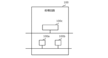
- FIG. 5 is a hardware configuration diagram of the main parts of the elevator system according to the first embodiment.
- Each function of the elevator system can be realized by a processing circuit 100.
- the processing circuit 100 includes at least one processor 100a and at least one memory 100b.
- the processing circuit may include at least one dedicated hardware 100c in addition to the processor 100a and memory 100b, or as a substitute for them.
- each function of the building system is realized by software, firmware, or a combination of software and firmware. At least one of the software and firmware is written as a program.
- the program is stored in the memory 100b.
- the processor 100a realizes each function of the elevator system by reading and executing the program stored in the memory 100b.
- the processor 100a is also called a CPU (Central Processing Unit), processing device, arithmetic unit, microprocessor, microcomputer, or DSP.
- the memory 100b is composed of non-volatile or volatile semiconductor memory such as RAM, ROM, flash memory, EPROM, and EEPROM.
- processing circuitry comprises dedicated hardware 100c
- the processing circuitry may be implemented, for example, as a single circuit, a composite circuit, a programmed processor, a parallel programmed processor, an ASIC, an FPGA, or a combination thereof.
- Each function of the elevator system can be realized by a processing circuit. Alternatively, all the functions of the elevator system can be realized collectively by a processing circuit. Some of the functions of the elevator system can be realized by dedicated hardware 100c, and other parts can be realized by software or firmware. In this way, the processing circuit realizes each function of the building system by dedicated hardware 100c, software, firmware, or a combination of these.
- Embodiment 2 In the second embodiment, differences from the example disclosed in the first embodiment will be described in particular detail. For features not described in the second embodiment, any of the features of the example disclosed in the first embodiment may be adopted.
- FIG. 6 is a block diagram showing functions of the elevator system according to embodiment 2.
- the second relay device 40 according to embodiment 2 further includes a door-open determination unit 406 in addition to the functions of the second relay device 40 according to embodiment 1.
- the door-opening determination unit 406 has the function of determining whether the assigned car selected by the selection unit 404 has arrived at the boarding floor and the door is open, based on the elevator information stored in the elevator information storage unit 420.
- FIG. 7 is a flowchart showing an example of operation of the elevator system according to embodiment 2. Here, a series of operations will be described, from when the elevator system executes the process of the flowchart shown in Fig. 5 to when it registers a boarding floor car call for the robot 1, to when it transmits a boarding instruction to the robot 1.
- step S200 the door opening judgment unit 406 judges whether the door opening condition is satisfied, that is, the door of the assigned car is open at the boarding floor of the robot 1, based on the elevator information stored in the elevator information storage unit 420.
- the door opening judgment unit 406 judges whether the current car position of the assigned car is the boarding floor, based on the car position information, and whether the door opening button light for the assigned car is on, based on the lighting information of the door opening button light. As a result, if at least one of these judgments is not satisfied, the process returns to step S200 again, and if both of these judgments are satisfied, the process proceeds to the next step S202.
- step S202 the transmitting unit 402 transmits a registration request for a destination floor car call for the assigned car selected by the selecting unit 404 to the receiving unit 301 of the first relay device 30 corresponding to the assigned car.
- step S204 the processing proceeds to step S204.
- step S204 the transmission unit 402 transmits an instruction for the robot to board the assigned car selected by the selection unit 404 to the reception unit 22 of the robot server 2.
- the door-open determination unit 406 of the second relay device 40 determines that the door of the assigned car is open at the floor where the robot 1 boards, it proceeds to the sending process of registering a car call for the destination floor. This makes it possible to register the destination floor immediately before the robot 1 boards, which has the effect of reducing the risk of a call being made to the destination floor being wasted.
- Embodiment 3 In the third embodiment, differences from the examples disclosed in the first or second embodiment will be described in particular detail. For features not described in the third embodiment, any of the features of the examples disclosed in the first or second embodiment may be adopted.
- Functions of the elevator system according to embodiment 3 Fig. 8 is a block diagram showing functions of an elevator system according to embodiment 3.
- the robot server 2 according to embodiment 3 further includes a confinement determination unit 23 in addition to the functions of embodiment 1-2.
- the second relay device 40 according to embodiment 3 further includes a robot operation determination unit 407 and an evacuation floor selection unit 408 in addition to the functions of the second relay device 40 according to embodiment 1-2.
- the trapped-in judging unit 23 has the function of judging that the robot 1 is trapped in the car 11 and notifying the building manager or the like. There are no limitations on the configuration of the trapped-in judging unit 23.
- the receiving unit 22 of the robot server 2 receives elevator information transmitted from the transmitting unit 402 of the second relay device 40. Then, the trapped-in judging unit 23 judges whether the robot 1 is trapped in the car 11 based on the received elevator information.
- the robot operation determination unit 407 has a function of determining whether to stop or resume robot operation, which transports the robot 1 to the destination floor, based on the elevator information stored in the elevator information storage unit 420. Specifically, the robot operation determination unit 407 reads out in-car destination floor button registration availability information acquired when the car 11 most recently stopped in a non-directional manner. The robot operation determination unit 407 then determines whether the condition is met that the destination floor of the robot 1 is included in the security restricted floor that cannot be registered in the in-car destination floor button registration availability information that has been read out. If the condition is met, the robot operation determination unit 407 then determines to stop robot operation.
- the robot operation determination unit 407 also determines whether to resume robot operation if the condition is no longer met within a predetermined waiting time after it has been determined that robot operation should be stopped.
- the time constraint on the waiting time is set to reduce the possibility of the robot 1 being trapped inside the car 11 and having to wait for a long time due to robot operation being stopped due to factors on the elevator side.
- the waiting time can be set as appropriate.
- the evacuation floor selection unit 408 has a function of selecting an evacuation floor to which the robot 1 is to escape, based on the elevator information stored in the elevator information storage unit 420. When the robot operation changes from suspended to resumed, it is required that the robot in the car 11 is quickly evacuated outside the car 11.
- the evacuation floor selection unit 408 selects an evacuation floor to which the robot in the car 11 is to escape, when the robot operation changes from suspended to resumed.
- FIG. 9 shows an example of the selection of an evacuation floor by the evacuation floor selection unit 408.
- the floors of the facility range from 1F to 7F
- the boarding floor of robot 1 is 2F
- the destination floor is 6F
- the car 11 in which robot 1 is riding is traveling from 2F to 6F
- the current car position is 3F.
- the evacuation floor selection unit 408 acquires the elevator status of the unit corresponding to the assigned car in which the robot 1 is riding, based on the elevator information stored in the elevator information storage unit 420.
- the elevator status here includes security restricted floor information and information on the distance from the current car position.
- a priority is set for the use of this information.
- the order of security restricted floor determination information and information on the distance from the current car position is from highest to lowest priority.
- the evacuation floor selection unit 408 first performs a judgment process based on the highest priority security restricted floor judgment information.
- the evacuation floor selection unit 408 judges whether each floor is a security restricted floor based on the in-car destination floor button registration availability information stored in the elevator information storage unit 420.
- the evacuation floor selection unit 408 reads out the in-car destination floor button registration availability information acquired at the most recent non-directional stop of the car 11, similar to the setting operation by the priority setting unit 403. Then, the evacuation floor selection unit 408 judges whether each floor is included in the security restricted floors that cannot be registered in the in-car destination floor button registration availability information that has been read out.
- the evacuation floor selection unit 408 excludes the security restricted floors 4F and 6F from the evacuation floor candidates, and provisionally sets the service floors 1F to 3F, 5F, and 7F as evacuation floor candidates.
- the evacuation floor selection unit 408 performs a determination process based on the distance from the current car position, which has the next highest priority.
- the evacuation floor selection unit 408 selects, from among the multiple candidate evacuation floors, the floor that is the shortest distance from the current car position in the current running direction of the car as the evacuation floor.
- FIG. 10 is a flowchart showing an example of the operation of the elevator system according to embodiment 3.
- a series of operations will be described, from when the elevator system transmits a boarding instruction to the robot 1 by executing the process of the flowchart shown in FIG. 7 until when it transmits a disembarking instruction to the robot 1.
- step S300 the second relay device 40 determines whether a request to stop robot operation has been issued due to a factor on the robot side.
- the second relay device 40 determines whether the receiving unit 401 has received a robot operation stop signal sent by the robot server 2. If the result of the determination is not affirmative, the process proceeds to step S302, and if the determination is affirmative, the process proceeds to step S304.
- step S302 the robot operation determination unit 407 of the second relay device 40 determines whether a determination has been made to stop robot operation due to a factor on the elevator side. If the determination is not successful, the process proceeds to step S306, and if the determination is successful, the process proceeds to step S308.
- step S304 the second relay device 40 determines whether the robot has returned to being operable.
- the second relay device 40 determines whether the receiving unit 401 has received a robot operation return signal within a predetermined waiting time after receiving a robot operation stop signal. If the result of the determination is not affirmative, the process proceeds to step S310, and if the determination is affirmative, the process proceeds to step S308.
- step S306 the door open determination unit 406 of the second relay device 40 determines whether the door of the car 11 is open at the destination floor based on the elevator information.
- the door open determination unit 406 determines whether the conditions are met in the car position information that the current car position is the destination floor and the door open button light illumination information is in the illuminated state. If the result is that the determination is not met, the process returns to step S306 again, and if the determination is met, the process proceeds to step S318.
- step S308 the evacuation floor selection unit 408 of the second relay device 40 selects an evacuation floor.
- the processing proceeds to step S312.
- step S310 the robot 1 is manually removed from the car 11.
- the confinement determination unit 23 determines that the robot 1 is confined in the car 11 and notifies the building manager, etc.
- step S312 the evacuation floor selection unit 408 of the second relay device 40 determines whether an elevator call is possible at the evacuation floor.
- the evacuation floor selection unit 408 determines whether the condition that the evacuation floor is located ahead in the elevator's travel direction from the current elevator position is met. If the result shows that the determination is not met, the process returns to step S312 again, and if the determination is met, the process proceeds to step S314.
- step S314 the transmitting unit 402 of the second relay device 40 transmits a registration request for a car call to the evacuation floor selected by the evacuation floor selecting unit 408 to the receiving unit 301 of the first relay device 30.
- step S314 the processing proceeds to step S316.
- step S316 the door open determination unit 406 of the second relay device 40 determines whether the door of the car 11 is open at the evacuation floor based on the elevator information.
- the door open determination unit 406 determines whether the conditions are met in the car position information that the current car position is the evacuation floor and the door open button light illumination information is in the illuminated state. If the result is that the determination is not met, the process returns to step S316 again, and if the determination is met, the process proceeds to step S318.
- step S318 the transmitter 402 of the second relay device transmits a robot disembarkation instruction to the receiver 22 of the robot server 2.
- the evacuation floor selection unit 408 performs evacuation floor selection processing. This leaves open the possibility of proceeding to resume robot operation even if robot operation is temporarily stopped due to a robot malfunction or the like. This reduces the effort required to manually remove the robot 1 from the car.
- the second relay device 40 can also distinguish between security restricted floors and floors behind, based on the in-car destination floor button registration availability information acquired at the time of the car 11's most recent non-directional stop. This can reduce the possibility of erroneously determining that a rear floor is a security restricted floor, thereby reducing erroneous determinations in the selection process for evacuation floors.
- the evacuation floor selection unit 408 prioritizes floors that are closer to the current car position during the evacuation floor selection process, allowing the robot 1 to be evacuated as quickly as possible.
- Embodiment 4 differ from the examples disclosed in the first to third embodiments will be described in particular detail. For features not described in the fourth embodiment, any of the features of the examples disclosed in the first to third embodiments may be adopted.
- the second relay device 40 of embodiment 4 further includes an elevator operation determination unit 409 and an erroneous determination prevention unit 410 in addition to the functions of the second relay device 40 of embodiment 3.
- the elevator operation determination unit 409 has the function of determining whether the operating status of the car 11 of each unit is in operation or out of service based on the elevator information stored in the elevator information storage unit 420.
- the erroneous judgment prevention unit 410 has a function of preventing the elevator operation judgment unit 409 from erroneously judging that the elevator is out of service when the car position is at the terminal floor, based on the elevator information stored in the elevator information storage unit 420.
- Fig. 12 is a flowchart showing an operation example of the elevator system according to embodiment 4. The routine shown in Fig. 12 is constantly executed for each unit in the elevator system.
- step S400 of the routine shown in FIG. 12 the elevator operation determination unit 409 determines whether the operating state of the car 11 of each unit is in operation or out of service based on the elevator information stored in the elevator information storage unit 420.
- the elevator operation determination unit 409 determines that the elevator is out of service if the in-car destination floor buttons for all floors are not registered and if the in-car destination floor buttons for all floors cannot be registered. Otherwise, it determines that the elevator is in operation.
- the process proceeds to step S402
- if the elevator is out of service the process proceeds to step S404.
- step S402 the transmitting unit 402 of the second relay device 40 transmits a notification that the elevator is in operation to the receiving unit 22 of the robot server 2.
- step S402 the process proceeds to step S406.
- step S404 the transmitting unit 402 of the second relay device 40 transmits a notification that the elevator is out of service to the receiving unit 22 of the robot server 2.
- this routine processing ends.
- step S406 the erroneous judgment prevention unit 410 judges whether the condition that the current car position is located at the terminal floor is satisfied based on the elevator information stored in the elevator information storage unit 420. If the condition is not satisfied, the process returns to step S406. On the other hand, if the condition is satisfied, the process proceeds to step S408.
- step S408 the erroneous judgment prevention unit 410 judges whether the car 11 has reversed direction or stopped in a non-directional manner based on the elevator information stored in the elevator information storage unit 420. If the judgment is not found to be true, the process returns to step S408. On the other hand, if the judgment is found to be true, this routine is terminated.
- the second relay device 40 can determine in the elevator operation determination unit 409 whether the elevator car is in operation or out of service, and notify the robot server 2 of the determination result in real time.
- the determination result in the elevator operation determination unit 409 can also be used as the elevator status used in the setting operation in the priority setting unit 403. In this case, for example, candidate cars that are out of service may be excluded from the allocation candidates.
- the erroneous judgment prevention unit 410 can suspend the elevator operation judgment unit 409 until it is determined that the car will reverse direction or stop in a non-directional manner. This makes it possible to prevent the elevator operation judgment unit 409 from making an erroneous judgment when all floors become rear floors when the car is located at the terminal floor.
- Embodiment 5 differ from the examples disclosed in the first to fourth embodiments will be described in detail. For features not described in the fifth embodiment, any of the features of the examples disclosed in the first to fourth embodiments may be adopted.
- Configuration of a building system according to embodiment 5 Fig. 13 is a configuration diagram of a building system according to embodiment 5.
- the elevator system which is an internal system of the building system in this embodiment, is a relay device 50 that combines the multiple first relay devices 30 and second relay devices 40 of the elevator system in embodiments 1-4.
- Other configurations are the same as those of the building systems in the respective embodiments, and therefore detailed description will be omitted.
- the relay device 50 is electrically connected to each car 11's respective car control device 13 via a relay cable 17.
- the relay cable 17 connected to the relay device 50 is electrically connected to each car 11's respective car control device 13 and the car transmission cable 16 connecting the car 11.
- the relay device 50 is provided in the machine room 5.
- the relay device 50 is electrically connected to the robot server 2 via a cable 18.
- the relay device 50 may also be connected to the robot server 2 wirelessly.
- the relay device 50 may also be provided in the management room 3.
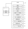
- Fig. 14 is a block diagram showing functions of an elevator system according to embodiment 5.
- the relay device 50 according to embodiment 5 includes a receiving unit 411 instead of the receiving unit 401, and a transmitting unit 312 instead of the transmitting unit 402.
- Other functions of the relay device 50 in Fig. 14 are similar to those of the second relay device in Fig. 11.
- the transmitting unit 21 of the robot server 2 has a function to transmit a usage request including information on the call of the robot 1 to the receiving unit 411 of the relay device 50, and a function to transmit a robot operation stop signal and a robot operation return signal to the receiving unit 411 of the relay device 50.
- the receiving unit 22 of the robot server 2 has a function to receive, from the transmitting unit 312 of the relay device 50, assigned car information that specifies the car 11 to which the call of the robot 1 is assigned.
- the receiving unit 411 of the relay device 50 has a function to receive a usage request and a robot operation stop signal from the transmitting unit 21 of the robot server 2, and a function to receive elevator information from the individual unit control devices 13.
- the receiving unit 411 of the relay device 50 has a function to receive elevator information from the individual unit control devices 13 of the corresponding unit every time the elevator information for that unit changes.
- the transmission unit 312 of the relay device 50 has a function of transmitting a registration request for a boarding floor car call for the assigned car selected by the selection unit 404 and a registration request for a destination floor car call for the assigned car to the corresponding car control device 13.
- the transmission unit 312 of the relay device 50 also has a function of transmitting information identifying the assigned car selected by the selection unit 404 to the reception unit 22 of the robot server 2.
- the functions of the transmitting unit 21 and the receiving unit 22 provided in the robot server 2 in the embodiments 1-5 may be provided in the robot 1.
- the second relay device 40 or the relay device 50 may communicate directly with the robot 1 without going through the robot server 2.
- Center Relay device 100 processing circuit, 100a processor, 100b memory, 100c dedicated hardware, 301 receiving unit, 302 transmitting unit, 312 transmitting unit, 401 receiving unit, 402 transmitting unit, 403 ranking setting unit, 404 selection unit, 405 transmission timing determination unit, 406 door opening determination unit, 407 robot operation determination unit, 408 evacuation floor selection unit, 409 elevator operation determination unit, 410 erroneous determination prevention unit, 411 receiving unit, 420 elevator information storage unit
Landscapes
- Engineering & Computer Science (AREA)
- Automation & Control Theory (AREA)
- Elevator Control (AREA)
Abstract
エレベーターとロボットとの連携によりロボットの乗降を実現するエレベーターシステムを提供するにあたり、モダニゼーション又はソフト改造に携わる人の負担を省力する。 エレベーターシステムは、対応するかごのかご操作盤から得られるエレベーター情報を受信し、かご操作盤から実行可能な指令を各台制御装置へと送信しうるように各々が接続される複数の第一中継装置と、複数の第一中継装置のそれぞれと通信しうるように接続された第二中継装置と、を備える。第二中継装置は、施設を移動する管理対象のロボットの乗車階から行先階までの呼びの情報を含む利用要求を受信し、利用要求に含まれるロボットの呼びを割り当てる割当かごを決定し、複数の第一中継装置のうち割当かごに対応する第一中継装置に、ロボットの呼びの登録要求を送信する。登録要求を受信した第一受信部は、受信したロボットの呼びの登録要求を各台制御装置に送信する。
Description
本開示は、エレベーターシステム、中継装置、第二中継装置、中継方法、及びコンピュータ読み取り可能な記録媒体に関する。
特許文献1には、エレベーター操作盤に着脱自在に装着されるボタン押下補助ユニットによって、無人搬送車が階移動を行う技術が開示されている。この技術の無人搬送車は、後付けで設置されたボタン押下補助ユニットと通信を行う通信部を備える。無人搬送車がエレベーター乗り場において上階行きボタンを押す信号を送信すると、ボタン押下補助ユニットにより上階行きボタンが押下される。また、ボタン押下補助ユニットは、該ボタンが点灯から消灯したことを検出し、その信号を無人搬送車へ発信する。
特許文献1の技術では、エレベーター操作盤から得られる情報及びエレベーター操作盤から実行可能な機能のみでロボットの乗降を実現する必要がある。このような制約の中で、ロボットがエレベーターと高度に連携できるようにするには、エレベーターのモダニゼーション又はソフト改造等において多大な人の労力が必要になる。
本開示は、上述のような課題を解決するためになされたもので、エレベーターとロボットとの連携によりロボットの乗降を実現するエレベーターシステムを提供するにあたり、モダニゼーション又はソフト改造に携わる人の負担を省力することを目的とする。
本開示のエレベーターシステムは、施設に設けられたエレベーターの複数のかごのうちのいずれかに各々が対応し、対応するかごのかご操作盤から得られるエレベーター情報を受信し、かご操作盤から実行可能な指令を各台制御装置へと送信しうるように各々が接続される複数の第一中継装置と、複数の第一中継装置のそれぞれと通信しうるように接続された第二中継装置と、を備える。第二中継装置は、施設を移動するロボットの乗車階から行先階までの呼びの情報を含む利用要求を受信する第二受信部と、複数の第一中継装置のうち、利用要求に含まれるロボットの呼びを割り当てる割当かごに対応する第一中継装置に、ロボットの呼びの登録要求を送信する第二送信部と、を備える。複数の第一中継装置の各々は、第二送信部が送信するロボットの呼びの登録要求を受信する第一受信部と、第一受信部が受信したロボットの呼びの登録要求を各台制御装置に送信する第一送信部と、を備える。
本開示の第二中継装置は、施設に設けられたエレベーターの複数のかごのうちのいずれかに各々が対応し、対応するかごのかご操作盤から得られるエレベーター情報を受信し、かご操作盤から実行可能な指令を各台制御装置へと送信しうるように各々が接続される複数の第一中継装置のそれぞれと通信しうるように接続される。第二中継装置は、施設を移動するロボットの乗車階から行先階までの呼びの情報を含む利用要求を受信する第二受信部と、複数の第一中継装置のうち、利用要求に含まれるロボットの呼びを割り当てる割当かごに対応する第一中継装置に、各台制御装置に送信するためのロボットの呼びの登録要求を第一中継装置に送信する第二送信部と、を備える。
本開示の中継装置は、施設に設けられたエレベーターの複数のかごのそれぞれのかご操作盤から得られるエレベーター情報を受信し、かご操作盤から実行可能な指令を複数のかごのそれぞれに対応した各台制御装置へと送信しうるように接続される。中継装置は、施設を移動するロボットの乗車階から行先階までの呼びの情報を含む利用要求を受信する受信部と、複数のかごのそれぞれに対応した各台制御装置のうち、利用要求に含まれるロボットの呼びを割り当てる割当かごに対応する各台制御装置に、ロボットの呼びの登録要求を送信する送信部と、を備える。
本開示の中継方法は、施設に設けられたエレベーターの複数のかごのそれぞれのかご操作盤から得られるエレベーター情報を受信し、かご操作盤から実行可能な指令を複数のかごのそれぞれに対応した各台制御装置へと送信する。中継方法は、施設を移動するロボットの乗車階から行先階までの呼びの情報を含む利用要求を受信するステップと、エレベーター情報に基づいて、利用要求に含まれるロボットの呼びを割り当てる割当かごを決定するステップと、ロボットの呼びの登録要求を割当かごに対応した各台制御装置へと送信するステップと、を備える。
本開示のコンピュータ読み取り可能な記録媒体は、施設に設けられたエレベーターの複数のかごのそれぞれのかご操作盤から得られるエレベーター情報を受信し、かご操作盤から実行可能な指令を複数のかごのそれぞれに対応した各台制御装置へと送信することをコンピュータに実行させる中継プログラムを記録している。中継プログラムは、施設を移動するロボットの乗車階から行先階までの呼びの情報を含む利用要求を受信し、エレベーター情報に基づいて、利用要求に含まれるロボットの呼びを割り当てる割当かごを決定し、ロボットの呼びの登録要求を割当かごに対応した各台制御装置へと送信することをコンピュータに実行させるように構成される。
本開示によれば、エレベーターとロボットとの連携によりロボットの乗降を実現するエレベーターシステムを提供するにあたり、モダニゼーション又はソフト改造に携わる人の負担を省力することが可能となる。
以下、図面を参照して実施の形態について説明する。なお、各図において共通する要素には、同一の符号を付して、重複する説明を省略する。
実施の形態1.
1-1.実施の形態1のビルシステムの構成
図1は、実施の形態1に係るビルシステムの構成図である。
1-1.実施の形態1のビルシステムの構成
図1は、実施の形態1に係るビルシステムの構成図である。
ビルシステムは、施設に適用される。施設は、例えば、屋内施設もしくは屋外施設、またはこれらを複合した施設などである。施設は、例えば、1つまたは複数の建物などからなる。施設は、例えば、建物などの一部であってもよい。施設に適用されるビルシステムは、施設を移動するロボット1を含む。この例において、ロボット1は、ロボットサーバー2による制御に基づいて稼働する。ロボット1は、ロボットサーバー2と無線によって通信する。施設において、管理室3が設けられている。管理室3は、施設の管理者などが施設の管理などを行う場所である。ロボットサーバー2は、例えば管理室3に設けられる。ビルシステムは、内部システムとしてエレベーターシステムを含む。
エレベーターシステムは、エレベーターを含む。施設において、エレベーターの昇降路4が設けられる。昇降路4は、上下方向を長手方向として複数の階床にわたる空間である。昇降路4の上部において、エレベーターの機械室5が設けられる。施設において、各々の階床に乗場6が設けられる。乗場6は、昇降路4に通じる場所である。
エレベーターは、複数のユニットと、群管理装置7と、を備える。各々のユニットは、巻上機8と、反らせ車9と、主ロープ10と、かご11と、釣合い錘12と、各台制御装置13と、を備える。群管理装置7、ならびに各々のユニットの巻上機8、反らせ車9、および各台制御装置13は、機械室5に設けられる。かご11および釣合い錘12は、昇降路4に設けられる。巻上機8は、駆動力を発生させるモータ、およびモータが発生させる駆動力によって回転するシーブを含む。主ロープ10は、巻上機8のシーブおよび反らせ車9に巻き掛けられる。主ロープ10は、巻上機8のシーブの一方側において、かご11の荷重を支持する。主ロープ10は、巻上機8のシーブの他方側において、釣合い錘12の荷重を支持する。かご11および釣合い錘12は、巻上機8のモータが発生させる駆動力によって、巻上機8のシーブおよび主ロープ10を介して昇降路の上下方向の互いに反対側に走行する。かご11は、昇降路4を走行することで、かご11の内部に乗車している利用者またはロボットなどを施設の複数の階床の間で輸送する。
各々のユニットの各台制御装置13は、同じユニットのかご11に対応する。各台制御装置13は、同じユニットの巻上機8に電気的に接続する。各台制御装置13は、かご伝送ケーブル16を通じて対応するかご11に接続される。各台制御装置13は、巻上機8の制御を通じて、かご11の走行を制御する。各々のユニットの各台制御装置13は、伝送ケーブル14を通じて群管理装置7に電気的に接続する。群管理装置7は、エレベーターの乗場6に設けられた図示されない乗場操作盤が受け付ける利用者の乗場呼びの情報を受け付ける。群管理装置7は、乗場呼びをいずれかのかご11に割り当てる。
かご11は、かご操作盤15を備える。かご操作盤15は、エレベーターの利用者によるかご呼びの操作を受け付けるエレベーター操作盤である。かご11のかご操作盤15が受け付けるかご呼びの情報は、かご伝送ケーブル16を通じて当該かご11に対応する各台制御装置13に送信される。
エレベーターシステムは、複数の第一中継装置30と、第二中継装置40と、を含む。第一中継装置30は、例えばプロトコルコンバータである。各々の第一中継装置30は、いずれかのユニットに対応する。第一中継装置30は、中継ケーブル17を介して対応するユニットの各台制御装置13に電気的に接続する。第一中継装置30に接続する中継ケーブル17は、第一中継装置30が対応するユニットにおいて各台制御装置13およびかご11を接続するかご伝送ケーブル16に電気的に接続されている。各々の第一中継装置30は、機械室5に設けられる。
第二中継装置40は、群管理装置7と別体の装置である。第二中継装置40は、管理室3に設けられる。第二中継装置40は、ケーブル18を介してロボットサーバー2に電気的に接続する。第二中継装置40は、無線によってロボットサーバー2に接続してもよい。第二中継装置40は、昇降路伝送ケーブル19を介して各々の第一中継装置30に電気的に接続する。第二中継装置40は、各々のユニットについて、第一中継装置30を介して各台制御装置13に接続している。すなわち、各々の第一中継装置30は、対応する各台制御装置13および第二中継装置40の間に介在している。
第二中継装置40は、コンピュータ読み取り可能な記録媒体に記録された中継プログラムを読み込み、当該中継プログラムに従って動作することで各機能を実行する。当該中継プログラムを記録する記録媒体は、例えば第二中継装置40に内蔵されるもの、または第二中継装置40に接続されるものなどであってもよい。当該中継プログラムは、例えばインターネットなどの通信網を通じて第二中継装置40にインストールされるものであってもよいし、当該中継プログラムを記録した外部の可搬な記録媒体から読み込ませることで第二中継装置40にインストールされるものであってもよい。
ビルシステムにおいて、ロボット1は、エレベーターを利用して施設の複数の階床の間を利用する。ロボット1がエレベーターを利用するときに、呼びの情報を含む利用要求が送信される。利用要求は、例えばロボット1を制御するロボットサーバー2から送信される。あるいは、利用要求は、ロボット1から送信されてもよい。ロボット1の呼びの情報は、ロボット1の乗車階及び行先階の情報を含む。利用要求は、第二中継装置40に送信される。第二中継装置40は、ロボット1の呼びをいずれかのかご11に割り当てる処理を行う。
ロボット1の呼びの割り当ては、例えばエレベーター情報に基づいて行われる。エレベーター情報は、例えば各々第一中継装置30から第二中継装置40に送信される。この例において、群管理装置7は、ロボット1の呼びをいずれかのかご11に割り当てる処理を行わない。第二中継装置40は、ロボット1の呼びを割り当てたかご11に対応する第一中継装置30に、当該呼びの情報を含む登録要求を送信する。第二中継装置40は、ロボット1の呼びを割り当てたかご11を特定する情報を、当該ロボット1を制御するロボットサーバー2に送信する。
第二中継装置40から呼びの登録要求を受け付けた第一中継装置30は、対応するかご11のかご操作盤15になりすまして、かご操作盤15から実行可能な指令を各台制御装置13に送信する。ここでは、第二中継装置40は、当該かご11のかご呼びとして当該呼びの情報を、当該かご11を制御する各台制御装置13に送信する。
1-2.実施の形態1のエレベーターシステムの機能
図2は、実施の形態1に係るエレベーターシステムの機能を示すブロック図である。
図2は、実施の形態1に係るエレベーターシステムの機能を示すブロック図である。
ロボットサーバー2は、送信部21と、受信部22と、を備える。第二中継装置40は、第二受信部としての受信部401と、第二送信部としての送信部402と、順位設定部403と、選択部404と、送信タイミング判定部405と、エレベーター情報記憶部420と、を備える。各々の第一中継装置30は、第一受信部としての受信部301と、第一送信部としての送信部302と、を備える。
ロボットサーバー2の送信部21は、ロボット1の呼びの情報を含む利用要求を、第二中継装置40の受信部401に送信する機能と、ロボット運転中止信号とロボット運転復帰信号を第二中継装置40の受信部401に送信する機能と、を有する。ここでのロボット運転は、ロボット1の呼びに応じたエレベーターの運転である。また、ロボット運転中止信号は、ロボット1の故障等によりロボット側の要因でロボット運転を中止することを要求する信号である。また、ロボット運転復帰信号は、ロボット運転中止中にロボット運転の復帰を要求する信号である。ロボットサーバー2の受信部22は、ロボット1の呼びが割り当てられたかご11を特定する割当かご情報を、第二中継装置40の送信部402から受信する機能を備える。
第二中継装置40の受信部401は、ロボットサーバー2の送信部21からの利用要求とロボット運転中止信号を受信する機能と、第一中継装置30の送信部302からのエレベーター情報と、を受信する機能を有する。
エレベーター情報記憶部420は、エレベーター情報を記憶する機能を有する。エレベーター情報は、各々のユニットのかご操作盤15から得られる情報を含む。各々のユニットについてのエレベーター情報は、かご11のかご位置情報、かご走行方向情報、戸開ボタン灯の点灯情報、かご内行先階ボタンの点灯情報、及びかご内行先階ボタン登録可否情報を含む。
順位設定部403は、ロボット1の呼びを割り当てる候補かごとしての順位を、複数のかご11の一部または全部に設定する機能を有する。順位設定部403は、エレベーター情報記憶部420が記憶するエレベーター情報に基づいて、各々のかご11の順位を設定する。
選択部404は、順位設定部403が順位を設定した候補かごから、ロボット1の呼びを割り当てる割当かごを選択する機能を有する。選択部404は、順位設定部403が設定した順位に基づいて割当かごを選択する。選択部404は、例えば、設定された順位が1位の候補かごを割当かごとして選択する。
送信タイミング判定部405は、エレベーター情報記憶部420に記憶されているエレベーター情報に基づいて、選択部404が選択した割当かごへの乗車階かご呼びを送信するタイミングを判定する機能を有する。送信タイミング判定部405は、例えば、かご11の走行方向の先に乗車階及び行先階がこの順に位置するタイミングを、乗車階かご呼びの送信タイミングと判定する。
第二中継装置40の送信部402は、選択部404が選択した割当かごへの乗車階かご呼びの登録要求と、当該割当かごへの行先階かご呼びの登録要求とを第一中継装置30の受信部301に送信する機能を有する。また、第二中継装置40の送信部402は、選択部404が選択した割当かごを特定する情報をロボットサーバー2の受信部22に送信する機能を有する。
第一中継装置30の受信部301は、第二中継装置40の送信部402からの呼びの登録要求などを受信する機能を有する。第一中継装置30の受信部301は、対応するユニットについてのエレベーター情報が変化するたびに、当該ユニットの各台制御装置13からエレベーター情報を受信する機能を有する。
第一中継装置30の送信部302は、第二中継装置40の送信部402が送信した呼びの登録要求を、対応するユニットのかご11のかご呼びとして、当該かご11を制御する各台制御装置13に送信する機能を有する。第一中継装置30の送信部302は、対応するユニットについてのエレベーター情報が変化するたびに、第二中継装置40の受信部401にエレベーター情報を送信する機能を有する。
1-3.エレベーターシステムの動作例
図3は、実施の形態1に係るエレベーターシステムの動作例を示すフローチャートである。ここでは、エレベーターシステムがロボット1の乗車階かご呼びを登録するまでの一連の動作について説明する。また、このフローチャートは、本開示の実施の形態に係る中継方法の一部を表してもいる。
図3は、実施の形態1に係るエレベーターシステムの動作例を示すフローチャートである。ここでは、エレベーターシステムがロボット1の乗車階かご呼びを登録するまでの一連の動作について説明する。また、このフローチャートは、本開示の実施の形態に係る中継方法の一部を表してもいる。
ステップS100では、第二中継装置40は、ロボットサーバー2の送信部21からロボット1の呼びの情報を含む利用要求を、受信部401が受信したかを判定する。その結果、判定の成立が認められた場合、処理はステップS102に進み、判定の成立が認められない場合、再びステップS100の処理に戻る。
ステップS102では、順位設定部403は、エレベーター情報記憶部420に記憶されている情報に基づいて、複数のかご11について候補かごとしての順位を設定する。ステップS102の処理が行われると、処理はステップS104に進む。
ステップS104では、選択部404は、順位設定部403が順位を1位に設定した候補かごを、割当かごとして選択する。ステップS104の処理が行われると、処理はステップS106に進む。
ステップS106では、送信タイミング判定部405は、エレベーター情報に基づいて、割当かごの走行方向の先に乗車階及び行先階がこの順に位置する条件が成立するかどうかを判定する。その結果、条件の成立が認められない場合、処理は再びステップS106に戻り、条件の成立が認められた場合、処理はステップS108に進む。
ステップS108では、送信部402は、選択部404が選択した割当かごへの乗車階かご呼びの登録要求を、割当かごに対応する第一中継装置30の受信部301に送信する。また、送信部402は、選択部404が選択した割当かごを特定する割当かご情報を、ロボットサーバー2の受信部22に送信する。その後、第二中継装置40の処理は、終了する。
続いて、図4を用いて、実施の形態1に係る第二中継装置40による割当かごの選択の例を説明する。図4は、実施の形態1に係る第二中継装置40による割当かごの選択の例を示している。
この例において、エレベーターは、A号機からH号機の8つのユニットを備えている。ロボットサーバー2などを通じて第二中継装置40に送信されるロボット1の利用要求は、当該ロボット1が乗車階から行先階に移動するときに送信される。順位設定部403は、エレベーター情報に基づいて、各々のユニットについてエレベーター状態を取得する。各々のユニットについてのエレベーター状態は、セキュリティ制限階判定情報、かご位置・走行方向情報、及びロボット1の乗車階から当該かご11までの距離の情報を含む。セキュリティ制限階判定情報は、セキュリティの観点から乗降が制限されているセキュリティ制限階を特定する情報である。かご位置・走行方向情報は、かご11の走行方向の先に乗車階及び行先階がこの順に位置するかどうかを示す情報である。割当候補の順位を設定するにあたり、これらの情報の利用には優先度が設定されている。この例において、セキュリティ制限階判定情報、かご位置・走行方向情報、及びロボット1の乗車階から当該かご11までの距離の情報の順序が、優先度の高い方からの順序である。
順位設定部403は、まず、最も優先度の高い、セキュリティ制限階判定情報に基づく判定処理を行う。順位設定部403は、エレベーター情報記憶部420に記憶されているかご内行先階ボタン登録可否情報に基づき、乗車階又は行先階がセキュリティ制限階であるかの判定を行う。ただし、エレベーターシステムによっては、かごの走行方向と逆側に位置する階床である背後階に対して、呼び登録を無効とする仕様に設定されている場合がある。このようなエレベーターシステムでは、背後階がかご内行先階ボタン登録可否情報において登録不可である階床に含まれてしまい、セキュリティ制限階を正確に特定できない可能性がある。
ここで、かご11の無方向停止時は、何れの階床も背後階にならないため、セキュリティ制限階を背後階と切り分けて判定することができる。そこで、順位設定部403は、かご11の直近の無方向停止時に取得したかご内行先階ボタン登録可否情報を読み出す。そして、順位設定部403は、ロボット1の乗車階又は行先階が、読み出したかご内行先階ボタン登録可否情報において登録不可であるセキュリティ制限階に含まれるかどうかを判定する。そして、順位設定部403は、乗車階又は行先階がセキュリティ制限階に含まれる号機のかご11を候補かごから除外する。図4に示す例では、順位設定部403は、乗車階及び行先階がサービス階であるA号機からD号機を暫定的に同率1位に設定し、乗車階又は行先階がセキュリティ制限階であるE号機からH号機を、候補かごから除外している。なお、順位設定部403は、例えば、候補かごから除外されたかご11について、以降の順位の設定の処理を省略してもよい。
続いて、順位設定部403は、次に優先度の高いかご位置・走行方向情報に基づく判定処理を行う。順位設定部403は、ロボット1の乗車階及び行先階が、かご11の走行方向の先にこの順に位置するかどうかを判定する。図4に示す例では、順位設定部403は、乗車階及び行先階がかご11の走行方向の先にこの順に位置するA号機及びB号機を暫定的に同率1位に設定し、乗車階及び行先階がかご11の走行方向の先にこの順に位置しないC号機及びD号機を暫定的に同率3位に設定する。
続いて、順位設定部403は、次に優先度の高い、乗車階からの距離に基づく判定処理を行う。順位設定部403は、乗車階からの距離がより短いかご11をより上位に設定する。順位設定部403は、暫定的に同率1位のA号機およびB号機に対して、例えば、乗車階からの距離が1階床分であるA号機を1位に設定し、乗車階からの距離が3階床分であるB号機を2位に設定する。また、順位設定部403は、暫定的に同率3位のC号機およびD号機に対して、例えば、乗車階からの距離が1階床分であるC号機を3位に設定し、乗車階からの距離が2階床分であるD号機を4位に設定する。
エレベーター状態に基づく順位の設定を行った上で順位が同率の候補かごがある場合に、順位設定部403は、ユニットの番号の若いかご11などをより上位に設定し、順位が同率の候補かごが無いように設定する。
選択部404は、順位設定部403が1位に順位を設定したA号機を、割当かごとして選択する。
1-4.実施の形態1のエレベーターシステムの作用効果
続いて、実施の形態1に係るエレベーターシステムの作用効果を説明する。
続いて、実施の形態1に係るエレベーターシステムの作用効果を説明する。
第二中継装置40は、ロボットサーバー2からの利用要求を受け、利用要求に含まれる呼びを割り当てる割当かごを選択する。第二中継装置40は、昇降路伝送ケーブル19を介して、当該呼びの登録要求を、割当かごを制御する各台制御装置13に接続する第一中継装置30に送信する。当該第一中継装置30は、割当かごのかご操作盤15になりすまして、当該登録要求をかご呼びとして当該各台制御装置13に送信する。このように、群管理装置7が第二中継装置40などと通信する機能を必要としないので、通信機能を搭載しない群管理装置7についてもエレベーターおよびロボット1の連携が可能になる。また、旧機種のエレベーターとロボット1とを連携させるにあたり、エレベーターのモダニゼーションおよび群管理装置7のソフトウェア改造などが必要にならないので、エレベーターの管理を行う管理者などの費用面および管理作業面などの負担が抑えられる。
また、第二中継装置40は、かご11の直近の無方向停止時に取得したかご内行先階ボタン登録可否情報を基に、セキュリティ制限階を背後階と切り分けて判定することができる。これにより、背後階をセキュリティ制限階と誤判定する可能性を減らすことができるので、背後階を候補かごに含めることができる。これにより、候補かごの対象が増えるので、運行効率を高めるための適切な割当かごを選択することができる。
また、第二中継装置40は、エレベーター情報に基づいて、乗車階及び行先階がかご11の走行方向の先にこの順に位置する号機を、そうでない号機よりも上位の順位に設定することができる。これにより、乗車階から行先階へとより円滑に移動可能なかご11を上位の順位に設定することができるので、運行効率が上がる。
また、順位設定部403は、エレベーター情報記憶部420に記憶している情報を基に、割当候補としての順位を設定する。選択部404は、順位設定部403が1位に設定した候補かごを割当かごとして選択する。これにより、第二中継装置40は、ロボット1が乗車可能で、かつ、乗車階に早くに到着するかご11の割り当てができるようになる、という効果が得られる。また、第二中継装置40が割当かごを選択するため、群管理装置7の処理負荷が低減できるというさらなる効果が得られる。
第二中継装置40は、割当かごの走行方向に、ロボット1の乗車階と行先階がこの順番に位置する条件が成立した場合に、ロボット1の乗車階にかご呼びを送信するタイミングであると判定する。ロボット1の乗車階と行先階が例えば背後階に位置するときにそれらの階にかご呼びがされると、かご11の方向反転時にかご呼びが消失する事象が発生する可能性がある。上記条件の判定は、そのような事象を避けることができるという効果を奏する。さらに、ロボット1の乗車後もかご11の走行方向が反転することなく、スムーズに行先階まで移動できるという効果を奏する。
1-5.変形例
実施の形態1のエレベーターシステムは、以下のような変形した態様を採用してもよい。なお、これらの変形例は、後述する他の実施の形態のエレベーターシステムにも適用しうる。
実施の形態1のエレベーターシステムは、以下のような変形した態様を採用してもよい。なお、これらの変形例は、後述する他の実施の形態のエレベーターシステムにも適用しうる。
ロボット1は、第二中継装置40との通信を、ロボットサーバー2を介さずに行ってもよい。
また、ロボットサーバー2および第二中継装置40の機能の一部または全部は、施設の外部に設けられた装置に搭載されていてもよい。ロボットサーバー2および第二中継装置40の機能の一部または全部は、複数のハードウェアにわたって実装されていてもよい。このとき、各ハードウェアは、インターネットなどの通信ネットワークを通じて互いに通信可能に接続される。また、ロボットサーバー2および第二中継装置40の機能の一部または全部は、クラウドサービス上の処理および記憶のリソースによって実装されていてもよい。
図5は、実施の形態1に係るエレベーターシステムの主要部のハードウェア構成図である。エレベーターシステムの各機能は、処理回路100により実現し得る。処理回路100は、少なくとも1つのプロセッサ100aと少なくとも1つのメモリ100bとを備える。処理回路は、プロセッサ100aおよびメモリ100bと共に、あるいはそれらの代用として、少なくとも1つの専用ハードウェア100cを備えてもよい。
処理回路がプロセッサ100aとメモリ100bとを備える場合、ビルシステムの各機能は、ソフトウェア、ファームウェア、またはソフトウェアとファームウェアとの組み合わせで実現される。ソフトウェアおよびファームウェアの少なくとも一方は、プログラムとして記述される。そのプログラムはメモリ100bに格納される。プロセッサ100aは、メモリ100bに記憶されたプログラムを読み出して実行することにより、エレベーターシステムの各機能を実現する。
プロセッサ100aは、CPU(Central Processing Unit)、処理装置、演算装置、マイクロプロセッサ、マイクロコンピュータ、DSPともいう。メモリ100bは、例えば、RAM、ROM、フラッシュメモリ、EPROM、EEPROMなどの、不揮発性または揮発性の半導体メモリなどにより構成される。
処理回路が専用ハードウェア100cを備える場合、処理回路は、例えば、単一回路、複合回路、プログラム化したプロセッサ、並列プログラム化したプロセッサ、ASIC、FPGA、またはこれらの組み合わせで実現される。
エレベーターシステムの各機能は、それぞれ処理回路で実現することができる。あるいは、エレベーターシステムの各機能は、まとめて処理回路で実現することもできる。エレベーターシステムの各機能について、一部を専用ハードウェア100cで実現し、他部をソフトウェアまたはファームウェアで実現してもよい。このように、処理回路は、専用ハードウェア100c、ソフトウェア、ファームウェア、またはこれらの組み合わせでビルシステムの各機能を実現する。
実施の形態2.
実施の形態2において、実施の形態1で開示される例と相違する点について特に詳しく説明する。実施の形態2で説明しない特徴については、実施の形態1で開示される例のいずれの特徴が採用されてもよい。
実施の形態2において、実施の形態1で開示される例と相違する点について特に詳しく説明する。実施の形態2で説明しない特徴については、実施の形態1で開示される例のいずれの特徴が採用されてもよい。
2-1.実施の形態2のエレベーターシステムの機能
図6は、実施の形態2に係るエレベーターシステムの機能を示すブロック図である。実施の形態2の第二中継装置40は、実施の形態1の第二中継装置40の機能に加えて、更に戸開判定部406を備える。
図6は、実施の形態2に係るエレベーターシステムの機能を示すブロック図である。実施の形態2の第二中継装置40は、実施の形態1の第二中継装置40の機能に加えて、更に戸開判定部406を備える。
戸開判定部406は、エレベーター情報記憶部420に記憶されているエレベーター情報に基づいて、選択部404が選択した割当かごが乗車階に到着して戸開しているかを判定する機能を有する。
2-2.実施の形態2のエレベーターシステムの動作例
図7は、実施の形態2に係るエレベーターシステムの動作例を示すフローチャートである。ここでは、エレベーターシステムが図5に示すフローチャートの処理を実行することによってロボット1の乗車階かご呼びを登録した後、ロボット1に乗車指示を送信するまでの一連の動作について説明する。
図7は、実施の形態2に係るエレベーターシステムの動作例を示すフローチャートである。ここでは、エレベーターシステムが図5に示すフローチャートの処理を実行することによってロボット1の乗車階かご呼びを登録した後、ロボット1に乗車指示を送信するまでの一連の動作について説明する。
ステップS200では、戸開判定部406は、エレベーター情報記憶部420に記憶されているエレベーター情報に基づいて、ロボット1の乗車階で割当かごが戸開している戸開条件が成立するかどうかを判定する。ここでは、戸開判定部406は、かご位置情報に基づいて、現在の割当かごのかご位置が乗車階であるかどうか、及び割当かごについての戸開ボタン灯の点灯情報に基づいて、戸開ボタン灯が点灯状態であるかどうかを判定する。その結果、これらの判定の少なくとも何れか一方の成立が認められない場合、処理は再びステップS200に戻り、これらの判定の両方の成立が認められた場合、処理は次のステップS202に進む。
ステップS202では、送信部402は、選択部404が選択した割当かごへの行先階かご呼びの登録要求を、割当かごに対応する第一中継装置30の受信部301に送信する。ステップS202の処理が実行されると、処理はステップS204に進む。
ステップS204では、送信部402は、選択部404が選択した割当かごへのロボット乗車指示を、ロボットサーバー2の受信部22に送信する。
2-3.実施の形態2のエレベーターシステムの作用効果
続いて、実施の形態2に係るエレベーターシステムの作用効果を説明する。
続いて、実施の形態2に係るエレベーターシステムの作用効果を説明する。
第二中継装置40の戸開判定部406は、ロボット1の乗車階で割当かごが戸開していると判断した場合に、行先階のかご呼び登録の送信処理に進むようにしている。これにより、ロボット1の乗車直前に行先階を登録することができるので、行先階が無駄呼びになるリスクを低減できるという効果を奏する。
実施の形態3.
実施の形態3において、実施の形態1又は実施の形態2で開示される例と相違する点について特に詳しく説明する。実施の形態3で説明しない特徴については、実施の形態1又は実施の形態2で開示される例のいずれの特徴が採用されてもよい。
実施の形態3において、実施の形態1又は実施の形態2で開示される例と相違する点について特に詳しく説明する。実施の形態3で説明しない特徴については、実施の形態1又は実施の形態2で開示される例のいずれの特徴が採用されてもよい。
3-1.実施の形態3のエレベーターシステムの機能
図8は、実施の形態3に係るエレベーターシステムの機能を示すブロック図である。実施の形態3のロボットサーバー2は、実施の形態1-2の機能に加えて、更に閉込め判定部23を備える。また、実施の形態3の第二中継装置40は、実施の形態1-2の第二中継装置40の機能に加えて、更にロボット運転判定部407と、退避階選択部408と、を備える。
図8は、実施の形態3に係るエレベーターシステムの機能を示すブロック図である。実施の形態3のロボットサーバー2は、実施の形態1-2の機能に加えて、更に閉込め判定部23を備える。また、実施の形態3の第二中継装置40は、実施の形態1-2の第二中継装置40の機能に加えて、更にロボット運転判定部407と、退避階選択部408と、を備える。
閉込め判定部23は、ロボット1がかご11内に閉込めになったことを判定し、ビル管理者などに通知させる機能を有する。閉込め判定部23の構成に限定はない。例えば、ロボットサーバー2の受信部22は、第二中継装置40の送信部402から送信されるエレベーター情報を受信する。そして、閉込め判定部23は、受信したエレベーター情報に基づいて、ロボット1がかご11内に閉込めになったかどうかを判定する。
ロボット運転判定部407は、エレベーター情報記憶部420に記憶されているエレベーター情報に基づいて、ロボット1を行先階へ輸送するロボット運転の中止と復帰を判定する機能を有する。具体的には、ロボット運転判定部407は、かご11の直近の無方向停止時に取得したかご内行先階ボタン登録可否情報を読み出す。そして、ロボット運転判定部407は、ロボット1の行先階が、読み出したかご内行先階ボタン登録可否情報において登録不可であるセキュリティ制限階に含まれる条件が成立するかどうかを判定する。そして、ロボット運転判定部407は、当該条件が成立した場合、ロボット運転の中止を判定する。
また、ロボット運転判定部407は、ロボット運転の中止が判定されてから予め定められた待機時間の間に当該条件が不成立に転じた場合、ロボット運転の復帰を判定する。ここで、待機時間の時間制約は、エレベーター側の要因でのロボット運転に中止により、ロボット1がかご11内に閉込められた状態が発生し、待ち続ける可能性を減らすために設けられている。待機時間は、適宜に設定できるものとする。
退避階選択部408は、エレベーター情報記憶部420に記憶されているエレベーター情報に基づいて、ロボット1が退避する退避階を選択する機能を有する。ロボット運転が中止から復帰に転じた場合、かご11内のロボットを速やかにかご11外へと退避させることが求められる。退避階選択部408は、ロボット運転が中止から復帰に転じた場合に、かご11内のロボットを退避させるための退避階を選択する。
図9は、退避階選択部408による退避階の選択の一例を示している。この例において、施設の階床は1Fから7Fまであり、ロボット1の乗車階は2Fであり、行先階は6Fである。そして、ロボット1が乗車したかご11は2Fから6Fに向かって走行中であり、現在かご位置は3Fである。
図9に示すとおり、退避階選択部408は、エレベーター情報記憶部420に記憶されているエレベーター情報に基づいて、ロボット1が乗車した割当かごに対応するユニットのエレベーター状態を取得する。ここでのエレベーター状態は、セキュリティ制限階情報と、現在かご位置からの距離の情報を含む。
退避階を選択するにあたり、これらの情報の利用には優先度が設定されている。この例において、セキュリティ制限階判定情報、及び現在かご位置からの距離の情報の順序が、優先度の高い方からの順序である。
退避階選択部408は、先ず最も優先度の高いセキュリティ制限階判定情報に基づく判定処理を行う。退避階選択部408は、エレベーター情報記憶部420に記憶されているかご内行先階ボタン登録可否情報に基づき、各階床がセキュリティ制限階であるかの判定を行う。ここでは、退避階選択部408は、順位設定部403による設定動作と同様に、かご11の直近の無方向停止時に取得したかご内行先階ボタン登録可否情報を読み出す。そして、退避階選択部408は、各階床が、読み出したかご内行先階ボタン登録可否情報において登録不可であるセキュリティ制限階に含まれるかどうかを判定する。そして、退避階選択部408は、セキュリティ制限階を退避階候補から除外する。図9に示す例では、退避階選択部408は、セキュリティ制限階の4Fと6Fを退避階候補から除外し、サービス階の1Fから3F、5F、7Fを暫定的に退避階候補に設定する。
セキュリティ制限階判定情報に基づく判定処理によって退避階候補が一意に決まらない場合、退避階選択部408は、次に優先度の高い、現在かご位置からの距離に基づく判定処理を行う。退避階選択部408は、複数の退避階候補のうち、かごの現在走行方向において現在かご位置からの距離が最も短い階を退避階として選択する。
3-2.実施の形態3のエレベーターシステムの動作例
図10は、実施の形態3に係るエレベーターシステムの動作例を示すフローチャートである。ここでは、エレベーターシステムが図7に示すフローチャートの処理を実行することによってロボット1に乗車指示を送信した後、ロボット1に降車指示を送信するまでの一連の動作について説明する。
図10は、実施の形態3に係るエレベーターシステムの動作例を示すフローチャートである。ここでは、エレベーターシステムが図7に示すフローチャートの処理を実行することによってロボット1に乗車指示を送信した後、ロボット1に降車指示を送信するまでの一連の動作について説明する。
ステップS300では、第二中継装置40は、ロボット側の要因でロボット運転中止の要求が出されたかどうかを判定する。ここでは、第二中継装置40は、ロボットサーバー2が送信したロボット運転中止信号を受信部401が受信したかどうかを判定する。その結果、判定の成立が認められない場合、処理はステップS302に進み、判定の成立が認められた場合、処理はステップS304に進む。
ステップS302では、第二中継装置40のロボット運転判定部407は、エレベーター側の要因によるロボット運転の中止判定がされたかどうかを判定する。その結果、判定の成立が認められない場合、処理はステップS306に進み、判定の成立が認められた場合、処理はステップS308に進む。
ステップS304では、第二中継装置40は、ロボット運転可能に復帰したかを判定する。ここでは、第二中継装置40は、ロボット運転中止信号を受信してから予め定められた待機時間の間にロボット運転復帰信号を受信部401が受信したかどうかを判定する。その結果、判定の成立が認められない場合、処理はステップS310に進み、判定の成立が認められた場合、処理はステップS308に進む。
ステップS306では、第二中継装置40の戸開判定部406は、エレベーター情報に基づいて、行先階においてかご11が戸開しているかどうかを判定する。ここでは、戸開判定部406は、かご位置情報において現在のかご位置が行先階であり、且つ戸開ボタン灯の点灯情報が点灯状態である条件が成立しているかどうかを判定する。その結果、判定の成立が認められない場合、処理は再びステップS306に戻り、判定の成立が認められた場合、処理はステップS318に進む。
ステップS308では、第二中継装置40の退避階選択部408は、退避階を選択する。ステップS308の処理が完了すると、処理はステップS312に進む。
ステップS310では、人手によりロボット1をかご11から降車させる。ここでは、閉込め判定部23は、ロボット1がかご11内に閉込めになったことを判定し、ビル管理者などに通知する。
ステップS312では、第二中継装置40の退避階選択部408は、退避階にかご呼びが可能かどうかを判定する。ここでは、退避階選択部408は、現在のかご位置からかごの走行方向の先に退避階が位置する条件が成立するかどうかを判定する。その結果、判定の成立が認められない場合、処理は再びステップS312に戻り、判定の成立が認められた場合、処理はステップS314に進む。
ステップS314では、第二中継装置40の送信部402は、退避階選択部408が選択した退避階へのかご呼びの登録要求を第一中継装置30の受信部301に送信する。ステップS314の処理が完了すると、処理はステップS316に進む。
ステップS316では、第二中継装置40の戸開判定部406は、エレベーター情報に基づいて、退避階においてかご11が戸開しているかどうかを判定する。ここでは、戸開判定部406は、かご位置情報において現在のかご位置が退避階であり、且つ戸開ボタン灯の点灯情報が点灯状態である条件が成立しているかどうかを判定する。その結果、判定の成立が認められない場合、処理は再びステップS316に戻り、判定の成立が認められた場合、処理はステップS318に進む。
ステップS318では、第二中継装置の送信部402は、ロボットサーバー2の受信部22にロボット降車指示を送信する。
3-3.実施の形態3のエレベーターシステムの作用効果
続いて、実施の形態3に係るエレベーターシステムの作用効果を説明する。
続いて、実施の形態3に係るエレベーターシステムの作用効果を説明する。
第二中継装置40は、ロボット運転中止信号を受信してから予め定められた待機時間の間にロボット運転復帰信号を受信部401が受信した場合、退避階選択部408による退避階の選択処理が行われる。これにより、ロボットが故障等によって一旦ロボット運転中止となったとしても、ロボット運転の復帰に進む可能性を残すことができる。これにより、人手によりロボット1をかご内から降ろす手間を削減することができる。
また、第二中継装置40は、かご11の直近の無方向停止時に取得したかご内行先階ボタン登録可否情報を基に、セキュリティ制限階を背後階と切り分けて判定することができる。これにより、背後階をセキュリティ制限階と誤判定する可能性を減らすことができるので、退避階の選択処理における誤判定を減らすことができる。
また、退避階選択部408は、退避階の選択処理において、現在かご位置からの距離が短い階床を優先するので、ロボット1をいち早く退避させることができる。
実施の形態4.
実施の形態4において、実施の形態1-3で開示される例と相違する点について特に詳しく説明する。実施の形態4で説明しない特徴については、実施の形態1―3で開示される例のいずれの特徴が採用されてもよい。
実施の形態4において、実施の形態1-3で開示される例と相違する点について特に詳しく説明する。実施の形態4で説明しない特徴については、実施の形態1―3で開示される例のいずれの特徴が採用されてもよい。
4-1.実施の形態4のエレベーターシステムの機能
図11は、実施の形態4に係るエレベーターシステムの機能を示すブロック図である。実施の形態4の第二中継装置40は、実施の形態3の第二中継装置40の機能に加えて、更にエレベーター運転判定部409と、誤判定防止部410と、を備える。
図11は、実施の形態4に係るエレベーターシステムの機能を示すブロック図である。実施の形態4の第二中継装置40は、実施の形態3の第二中継装置40の機能に加えて、更にエレベーター運転判定部409と、誤判定防止部410と、を備える。
エレベーター運転判定部409は、エレベーター情報記憶部420に記憶されているエレベーター情報に基づいて、各々のユニットのかご11の運転状態が運転中であるか休止中であるかを判定する機能を有する。
誤判定防止部410は、エレベーター情報記憶部420に記憶されているエレベーター情報に基づいて、かご位置が終端階のときに、エレベーター運転判定部409がエレベーター休止中と誤判定することを防止する機能を有する。
4-2.実施の形態4のエレベーターシステムの動作例
図12は、実施の形態4に係るエレベーターシステムの動作例を示すフローチャートである。図12に示すルーチンは、エレベーターシステムにおいて、各々のユニットに対して常時実行されている。
図12は、実施の形態4に係るエレベーターシステムの動作例を示すフローチャートである。図12に示すルーチンは、エレベーターシステムにおいて、各々のユニットに対して常時実行されている。
図12に示すルーチンのステップS400では、エレベーター運転判定部409は、エレベーター情報記憶部420に記憶されているエレベーター情報に基づいて、各々のユニットのかご11の運転状態が運転中であるか休止中であるかを判定する。ここでは、エレベーター運転判定部409は、全階のかご内行先階ボタンが登録されていない、且つ、全階のかご内行先階ボタンが登録不可である場合に、エレベーター休止中と判定する。それ以外は、エレベーター運転中と判定する。その結果、エレベーターが運転中である場合、処理はステップS402に進み、エレベーターが休止中である場合、処理はステップS404に進む。
ステップS402では、第二中継装置40の送信部402は、エレベーターが運転中である通知をロボットサーバー2の受信部22へ送信する。ステップS402の処理が完了すると、処理はステップS406に進む。
ステップS404では、第二中継装置40の送信部402は、エレベーターが休止中である通知をロボットサーバー2の受信部22へ送信する。ステップS404の処理が完了すると、本ルーチン処理は終了される。
ステップS406では、誤判定防止部410は、エレベーター情報記憶部420に記憶されているエレベーター情報に基づいて、現在のかご位置が終端階に位置している条件が成立するかを判定する。その結果、条件の成立が認められない場合、処理は再びステップS406に戻る。一方、条件の成立が認められた場合、処理はステップS408に移行する。
ステップS408では、誤判定防止部410は、エレベーター情報記憶部420に記憶されているエレベーター情報に基づいて、かご11が方向反転又は無方向停止をしたかどうかを判定する。その結果、判定の成立が認められない場合、処理は再びステップS408に戻る。一方、判定の成立が認められた場合、本ルーチンは終了される。
4-3.実施の形態4のエレベーターシステムの作用効果
続いて、実施の形態4に係るエレベーターシステムの作用効果を説明する。
続いて、実施の形態4に係るエレベーターシステムの作用効果を説明する。
第二中継装置40は、エレベーター運転判定部409においてエレベーターのかごが運転中であるか休止中であるかを判定し、その判定結果をロボットサーバー2にリアルタイムで通知することができる。また、エレベーター運転判定部409での判定結果は、順位設定部403における設定動作で利用されるエレベーター状態として利用することもできる。この場合、例えば、休止中の候補かごは、割当候補から除外することとしてもよい。
誤判定防止部410は、かご位置が終端階である場合に、かごの方向反転又は無方向停止が判定されるまで、エレベーター運転判定部409を保留することができる。これにより、かご位置が終端階に位置しているときに全階が背後階になり、エレベーター運転判定部409での判定が誤判定となることを防止することができる。
実施の形態5.
実施の形態5において、実施の形態1-4で開示される例と相違する点について特に詳しく説明する。実施の形態5で説明しない特徴については、実施の形態1―4で開示される例のいずれの特徴が採用されてもよい。
実施の形態5において、実施の形態1-4で開示される例と相違する点について特に詳しく説明する。実施の形態5で説明しない特徴については、実施の形態1―4で開示される例のいずれの特徴が採用されてもよい。
5-1.実施の形態5のビルシステムの構成
図13は、実施の形態5に係るビルシステムの構成図である。本実施の形態におけるビルシステムの内部システムであるエレベーターシステムは、実施の形態1-4におけるエレベーターシステムの複数の第一中継装置30及び第二中継装置40をまとめて中継装置50としたものである。それ以外の構成は各実施の形態におけるビルシステムと同様であるので、詳細な説明は省略する。
図13は、実施の形態5に係るビルシステムの構成図である。本実施の形態におけるビルシステムの内部システムであるエレベーターシステムは、実施の形態1-4におけるエレベーターシステムの複数の第一中継装置30及び第二中継装置40をまとめて中継装置50としたものである。それ以外の構成は各実施の形態におけるビルシステムと同様であるので、詳細な説明は省略する。
中継装置50は、中継ケーブル17を介して各かご11の各台制御装置13に電気的に接続する。中継装置50に接続する中継ケーブル17は、各かご11の各台制御装置13およびかご11を接続するかご伝送ケーブル16に電気的に接続されている。中継装置50は、機械室5に設けられる。
中継装置50は、ケーブル18を介してロボットサーバー2に電気的に接続する。中継装置50は、無線によってロボットサーバー2に接続してもよい。なお、中継装置50は、管理室3に設けられていてもよい。
5-2.実施の形態5のエレベーターシステムの機能
図14は、実施の形態5に係るエレベーターシステムの機能を示すブロック図である。実施の形態5の中継装置50は、図11に示す第二中継装置40の機能と比較して、受信部401の代わりに受信部411を備え、送信部402の代わりに送信部312を備える。図14の中継装置50が備える他の機能は、図11の第二中継装置と同様の構成である。
図14は、実施の形態5に係るエレベーターシステムの機能を示すブロック図である。実施の形態5の中継装置50は、図11に示す第二中継装置40の機能と比較して、受信部401の代わりに受信部411を備え、送信部402の代わりに送信部312を備える。図14の中継装置50が備える他の機能は、図11の第二中継装置と同様の構成である。
ロボットサーバー2の送信部21は、ロボット1の呼びの情報を含む利用要求を、中継装置50の受信部411に送信する機能と、ロボット運転中止信号とロボット運転復帰信号を中継装置50の受信部411に送信する機能と、を有する。ロボットサーバー2の受信部22は、ロボット1の呼びが割り当てられたかご11を特定する割当かご情報を、中継装置50の送信部312から受信する機能を備える。
中継装置50の受信部411は、ロボットサーバー2の送信部21からの利用要求とロボット運転中止信号を受信する機能と、各台制御装置13からのエレベーター情報と、を受信する機能を有する。中継装置50の受信部411は、対応するユニットについてのエレベーター情報が変化するたびに、当該ユニットの各台制御装置13からエレベーター情報を受信する機能を有する。
中継装置50の送信部312は、選択部404が選択した割当かごへの乗車階かご呼びの登録要求と、当該割当かごへの行先階かご呼びの登録要求とを対応するかごの各台制御装置13に送信する機能を有する。また、中継装置50の送信部312は、選択部404が選択した割当かごを特定する情報をロボットサーバー2の受信部22に送信する機能を有する。
なお、実施の形態1-5のロボットサーバー2が備えている送信部21及び受信部22の機能は、ロボット1が備えていてもよい。第二中継装置40又は中継装置50は、ロボットサーバー2を介さずにロボット1と直接通信するようにしてもよい。
1 ロボット、 2 ロボットサーバー、 3 管理室、 4 昇降路、 5 機械室、 6 乗場、 7 群管理装置、 8 巻上機、 9 反らせ車、 10 主ロープ、 12 釣合い錘、 13 各台制御装置、 14 伝送ケーブル、 15 かご操作盤、 16 かご伝送ケーブル、 17 中継ケーブル、 18 ケーブル、 19 昇降路伝送ケーブル、 21 送信部、 22 受信部、 23 閉込め判定部、 30 第一中継装置、 40 第二中継装置、50 中継装置、 100 処理回路、 100a プロセッサ、 100b メモリ、 100c 専用ハードウェア、 301 受信部、 302 送信部、312、送信部 401 受信部、 402 送信部、 403 順位設定部、 404 選択部、 405 送信タイミング判定部、 406 戸開判定部、 407 ロボット運転判定部、 408 退避階選択部、 409 エレベーター運転判定部、 410 誤判定防止部、411 受信部、 420 エレベーター情報記憶部
Claims (16)
- 施設に設けられたエレベーターの複数のかごのうちのいずれかに各々が対応し、対応するかごのかご操作盤から得られるエレベーター情報を受信し、前記かご操作盤から実行可能な指令を各台制御装置へと送信しうるように各々が接続される複数の第一中継装置と、
前記複数の第一中継装置のそれぞれと通信しうるように接続された第二中継装置と、を備え、
前記第二中継装置は、
前記施設を移動するロボットの乗車階から行先階までの呼びの情報を含む利用要求を受信する第二受信部と、
前記複数の第一中継装置のうち、前記利用要求に含まれる前記ロボットの呼びを割り当てる割当かごに対応する第一中継装置に、前記ロボットの呼びの登録要求を送信する第二送信部と、を備え、
前記複数の第一中継装置の各々は、
前記第二送信部が送信する前記ロボットの呼びの登録要求を受信する第一受信部と、
前記第一受信部が受信した前記ロボットの呼びの登録要求を前記各台制御装置に送信する第一送信部と、
を備えるエレベーターシステム。 - 前記エレベーター情報は、対応するかごについての、かご位置情報、かご走行方向情報、戸開ボタン灯の点灯情報、かご内行先階ボタンの点灯情報、及びかご内行先階ボタン登録可否情報のうちの少なくとも何れか1つを含み、
前記複数の第一中継装置の各々は、
前記エレベーター情報を前記第二中継装置に送信するように構成され、
前記第二中継装置は、
前記エレベーター情報を前記複数の第一中継装置の各々から受信し、
受信した前記エレベーター情報に基づいて、前記割当かごを決定する
請求項1に記載のエレベーターシステム。 - 前記第二中継装置は、
受信した前記エレベーター情報に基づいて、前記利用要求に含まれる前記ロボットの呼びを割り当てる候補かごとしての順位を、前記複数のかごの少なくともいずれかに設定する順位設定部と、
前記順位設定部が順位を設定した候補かごから、前記割当かごを選択する選択部と、
を更に備える請求項2に記載のエレベーターシステム。 - 前記エレベーター情報は、前記かご内行先階ボタン登録可否情報を含み、
前記順位設定部は、
受信した前記かご内行先階ボタン登録可否情報のうち、直近のかごの無方向停止時に取得したかご内行先階ボタン登録可否情報において登録不可とされる階床が前記乗車階又は前記行先階を含むかごを、前記候補かごの対象から除外するように構成される
請求項3に記載のエレベーターシステム。 - 前記エレベーター情報は、前記かご位置情報と前記かご走行方向情報を含み、
前記順位設定部は、
受信した前記かご位置情報及び前記かご走行方向情報に基づいて、現在のかごの位置からかごの走行方向の先に、前記乗車階と前記行先階がこの順番に位置する条件が成立するかどうかを判定し、当該条件の成立有無に基づいて、前記候補かごとしての順位を設定するように構成される
請求項3又は請求項4に記載のエレベーターシステム。 - 前記エレベーター情報は、前記かご位置情報と前記かご走行方向情報を含み、
前記順位設定部は、
受信した前記かご位置情報及び前記かご走行方向情報に基づいて演算される、現在のかごの位置から前記乗車階までの距離に基づいて、前記候補かごとしての順位を設定するように構成される
請求項3から請求項5の何れか1項に記載のエレベーターシステム。 - 前記第二中継装置は、
前記かご位置情報と前記かご走行方向情報に基づいて、現在の割当かごの位置からかごの走行方向の先に、前記乗車階と前記行先階が順番に位置する条件が成立するかどうかを判定し、前記条件が成立する場合に、前記割当かごへのかご呼び登録要求を送信する送信タイミング判定部をさらに備える
請求項3から請求項6の何れか1項に記載のエレベーターシステム。 - 前記第二中継装置は、
前記割当かごが前記乗車階で戸開している戸開条件が成立したかを判定する戸開判定部を更に備え、
前記第二送信部は、前記戸開条件が成立した場合、前記割当かごに対応する第一中継装置に、前記行先階のかご呼びの登録要求を送信するように構成される
請求項3から請求項7の何れか1項に記載のエレベーターシステム。 - 前記第二中継装置は、
エレベーター側の要因によるロボット運転の中止判定がされた場合、前記中止判定から待機時間の間に前記ロボット運転が可能に復帰したかを判定するロボット運転判定部を更に備える
請求項3から請求項8の何れか1項に記載のエレベーターシステム。 - 前記第二中継装置は、
前記ロボット運転判定部により前記ロボット運転が可能に復帰したことが判定された場合、前記ロボットが退避すべき退避階を選択する退避階選択部を備える
請求項9に記載のエレベーターシステム。 - 前記第二中継装置は、
前記エレベーターが運転中であるかどうかを判定するエレベーター運転判定部と、
前記エレベーターが終端階に位置している場合に、前記エレベーターが方向反転又は無方向停止するまで、前記エレベーター運転判定部における判定を保留する誤判定防止部と、
を備える請求項1から請求項10の何れか1項に記載のエレベーターシステム。 - 施設に設けられたエレベーターの複数のかごのうちのいずれかに各々が対応し、対応するかごのかご操作盤から得られるエレベーター情報を受信し、前記かご操作盤から実行可能な指令を各台制御装置へと送信しうるように各々が接続される複数の第一中継装置のそれぞれと通信しうるように接続された第二中継装置であって、
前記施設を移動するロボットの乗車階から行先階までの呼びの情報を含む利用要求を受信する第二受信部と、
前記複数の第一中継装置のうち、前記利用要求に含まれる前記ロボットの呼びを割り当てる割当かごに対応する第一中継装置に、前記各台制御装置に送信するための前記ロボットの呼びの登録要求を前記第一中継装置に送信する第二送信部と、
を備える第二中継装置。 - 施設に設けられたエレベーターの複数のかごのそれぞれのかご操作盤から得られるエレベーター情報を受信し、前記かご操作盤から実行可能な指令を前記複数のかごのそれぞれに対応した各台制御装置へと送信しうるように接続される中継装置であって、
前記施設を移動するロボットの乗車階から行先階までの呼びの情報を含む利用要求を受信する受信部と、
前記複数のかごのそれぞれに対応した各台制御装置のうち、前記利用要求に含まれる前記ロボットの呼びを割り当てる割当かごに対応する各台制御装置に、前記ロボットの呼びの登録要求を送信する送信部と、
を備える中継装置。 - 請求項13に記載の中継装置を備えるエレベーターシステム。
- 施設に設けられたエレベーターの複数のかごのそれぞれのかご操作盤から得られるエレベーター情報を受信し、前記かご操作盤から実行可能な指令を前記複数のかごのそれぞれに対応した各台制御装置へと送信する中継方法であって、
前記施設を移動するロボットの乗車階から行先階までの呼びの情報を含む利用要求を受信するステップと、
前記エレベーター情報に基づいて、前記利用要求に含まれる前記ロボットの呼びを割り当てる割当かごを決定するステップと、
前記ロボットの呼びの登録要求を前記割当かごに対応した各台制御装置へと送信するステップと、
を備える中継方法。 - 施設に設けられたエレベーターの複数のかごのそれぞれのかご操作盤から得られるエレベーター情報を受信し、前記かご操作盤から実行可能な指令を前記複数のかごのそれぞれに対応した各台制御装置へと送信することをコンピュータに実行させる中継プログラムを記録したコンピュータ読み取り可能な記録媒体であって、
前記中継プログラムは、
前記施設を移動するロボットの乗車階から行先階までの呼びの情報を含む利用要求を受信し、
前記エレベーター情報に基づいて、前記利用要求に含まれる前記ロボットの呼びを割り当てる割当かごを決定し、
前記ロボットの呼びの登録要求を前記割当かごに対応した各台制御装置へと送信する
ことをコンピュータに実行させる
ように構成されるコンピュータ読み取り可能な記録媒体。
Priority Applications (1)
| Application Number | Priority Date | Filing Date | Title |
|---|---|---|---|
| PCT/JP2022/036180 WO2024069797A1 (ja) | 2022-09-28 | 2022-09-28 | エレベーターシステム、中継装置、第二中継装置、中継方法、及びコンピュータ読み取り可能な記録媒体 |
Applications Claiming Priority (1)
| Application Number | Priority Date | Filing Date | Title |
|---|---|---|---|
| PCT/JP2022/036180 WO2024069797A1 (ja) | 2022-09-28 | 2022-09-28 | エレベーターシステム、中継装置、第二中継装置、中継方法、及びコンピュータ読み取り可能な記録媒体 |
Publications (1)
| Publication Number | Publication Date |
|---|---|
| WO2024069797A1 true WO2024069797A1 (ja) | 2024-04-04 |
Family
ID=90476630
Family Applications (1)
| Application Number | Title | Priority Date | Filing Date |
|---|---|---|---|
| PCT/JP2022/036180 WO2024069797A1 (ja) | 2022-09-28 | 2022-09-28 | エレベーターシステム、中継装置、第二中継装置、中継方法、及びコンピュータ読み取り可能な記録媒体 |
Country Status (1)
| Country | Link |
|---|---|
| WO (1) | WO2024069797A1 (ja) |
Citations (7)
| Publication number | Priority date | Publication date | Assignee | Title |
|---|---|---|---|---|
| JP2010023959A (ja) * | 2008-07-16 | 2010-02-04 | Fuji Heavy Ind Ltd | エレベータによる自律走行車の移動システム |
| JP2012018646A (ja) * | 2010-07-09 | 2012-01-26 | Murata Mach Ltd | 自律走行体移動システム |
| JP2020029322A (ja) * | 2018-08-21 | 2020-02-27 | 東芝エレベータ株式会社 | エレベータを用いた搬送システム、これに用いるエレベータ、およびエレベータ制御方法 |
| CN111170095A (zh) * | 2019-12-31 | 2020-05-19 | 北京猎户星空科技有限公司 | 一种电梯调度系统 |
| JP2020109039A (ja) * | 2019-01-07 | 2020-07-16 | 東芝エレベータ株式会社 | エレベータの制御システムおよび制御方法 |
| WO2021210186A1 (ja) * | 2020-04-18 | 2021-10-21 | 三菱電機株式会社 | 空気調和機動作システム、空気調和機およびサーバ |
| JP2022024765A (ja) * | 2020-07-28 | 2022-02-09 | 株式会社東芝 | 自律移動型ロボット及びプログラム |
-
2022
- 2022-09-28 WO PCT/JP2022/036180 patent/WO2024069797A1/ja unknown
Patent Citations (7)
| Publication number | Priority date | Publication date | Assignee | Title |
|---|---|---|---|---|
| JP2010023959A (ja) * | 2008-07-16 | 2010-02-04 | Fuji Heavy Ind Ltd | エレベータによる自律走行車の移動システム |
| JP2012018646A (ja) * | 2010-07-09 | 2012-01-26 | Murata Mach Ltd | 自律走行体移動システム |
| JP2020029322A (ja) * | 2018-08-21 | 2020-02-27 | 東芝エレベータ株式会社 | エレベータを用いた搬送システム、これに用いるエレベータ、およびエレベータ制御方法 |
| JP2020109039A (ja) * | 2019-01-07 | 2020-07-16 | 東芝エレベータ株式会社 | エレベータの制御システムおよび制御方法 |
| CN111170095A (zh) * | 2019-12-31 | 2020-05-19 | 北京猎户星空科技有限公司 | 一种电梯调度系统 |
| WO2021210186A1 (ja) * | 2020-04-18 | 2021-10-21 | 三菱電機株式会社 | 空気調和機動作システム、空気調和機およびサーバ |
| JP2022024765A (ja) * | 2020-07-28 | 2022-02-09 | 株式会社東芝 | 自律移動型ロボット及びプログラム |
Similar Documents
| Publication | Publication Date | Title |
|---|---|---|
| TWI273084B (en) | Method for controlling an elevator installation and elevator installation for carrying out the method | |
| US8132652B2 (en) | Elevator system including plurality of elevators operating in same hoistway | |
| KR101286320B1 (ko) | 엘레베이터 시스템에 사용자를 할당하는 방법 | |
| US8517149B2 (en) | Method of handling passenger requests during elevator modernization | |
| EA023522B1 (ru) | Лифтовая система | |
| JP2014504998A (ja) | エレベータ呼び及び供給かごの割り当てにおける自動化 | |
| CN110775744B (zh) | 多轿厢电梯以及多轿厢电梯控制方法 | |
| US6176351B1 (en) | Double deck elevator allocation controlling apparatus | |
| US20140262628A1 (en) | System Having Multiple Cabs in an Elevator Shaft and Control Method Thereof | |
| JPH04317966A (ja) | 残り応答時間に基づくエレベータ運行方法 | |
| US20190389692A1 (en) | Elevator dispatching | |
| JP5113962B2 (ja) | ダブルデッキエレベータシステムの制御装置および制御方法 | |
| WO2024069797A1 (ja) | エレベーターシステム、中継装置、第二中継装置、中継方法、及びコンピュータ読み取り可能な記録媒体 | |
| JP3073650B2 (ja) | ダブルデッキエレベーターの制御装置 | |
| JP7231096B1 (ja) | エレベーターシステム、中継装置、ビルシステム、中継方法、および中継プログラム | |
| GB2324170A (en) | Elevator dispatch system | |
| WO2000034170A1 (en) | Wireless transport system stop fixtures | |
| JP6781299B1 (ja) | 昇降機制御方法、及び昇降機制御装置 | |
| JP7435888B1 (ja) | エレベータ連携制御装置、エレベータシステム、エレベータ連携制御方法及びエレベータ連携制御プログラム | |
| WO2020026658A1 (ja) | エレベーター制御システム及びエレベーター制御方法 | |
| CN110775745B (zh) | 多轿厢电梯以及多轿厢电梯控制方法 | |
| JP7451661B1 (ja) | エレベータ制御装置、エレベータ制御方法およびプログラム | |
| JP2505645B2 (ja) | エレベ―タの制御装置 | |
| JP7359340B1 (ja) | エレベーターシステム及びエレベーターのかご割り当て方法 | |
| JP3457873B2 (ja) | ダブルデッキエレベーターの群管理制御装置 |
Legal Events
| Date | Code | Title | Description |
|---|---|---|---|
| 121 | Ep: the epo has been informed by wipo that ep was designated in this application |
Ref document number: 22960860 Country of ref document: EP Kind code of ref document: A1 |