WO2024062772A1 - ドアインナパネルの製造方法およびドアインナパネル - Google Patents
ドアインナパネルの製造方法およびドアインナパネル Download PDFInfo
- Publication number
- WO2024062772A1 WO2024062772A1 PCT/JP2023/027973 JP2023027973W WO2024062772A1 WO 2024062772 A1 WO2024062772 A1 WO 2024062772A1 JP 2023027973 W JP2023027973 W JP 2023027973W WO 2024062772 A1 WO2024062772 A1 WO 2024062772A1
- Authority
- WO
- WIPO (PCT)
- Prior art keywords
- inner panel
- mold
- door inner
- composite material
- injection molding
- Prior art date
- Legal status (The legal status is an assumption and is not a legal conclusion. Google has not performed a legal analysis and makes no representation as to the accuracy of the status listed.)
- Ceased
Links
Images





Classifications
-
- B—PERFORMING OPERATIONS; TRANSPORTING
- B29—WORKING OF PLASTICS; WORKING OF SUBSTANCES IN A PLASTIC STATE IN GENERAL
- B29C—SHAPING OR JOINING OF PLASTICS; SHAPING OF MATERIAL IN A PLASTIC STATE, NOT OTHERWISE PROVIDED FOR; AFTER-TREATMENT OF THE SHAPED PRODUCTS, e.g. REPAIRING
- B29C43/00—Compression moulding, i.e. applying external pressure to flow the moulding material; Apparatus therefor
- B29C43/02—Compression moulding, i.e. applying external pressure to flow the moulding material; Apparatus therefor of articles of definite length, i.e. discrete articles
- B29C43/18—Compression moulding, i.e. applying external pressure to flow the moulding material; Apparatus therefor of articles of definite length, i.e. discrete articles incorporating preformed parts or layers, e.g. compression moulding around inserts or for coating articles
-
- B—PERFORMING OPERATIONS; TRANSPORTING
- B29—WORKING OF PLASTICS; WORKING OF SUBSTANCES IN A PLASTIC STATE IN GENERAL
- B29C—SHAPING OR JOINING OF PLASTICS; SHAPING OF MATERIAL IN A PLASTIC STATE, NOT OTHERWISE PROVIDED FOR; AFTER-TREATMENT OF THE SHAPED PRODUCTS, e.g. REPAIRING
- B29C43/00—Compression moulding, i.e. applying external pressure to flow the moulding material; Apparatus therefor
- B29C43/32—Component parts, details or accessories; Auxiliary operations
- B29C43/36—Moulds for making articles of definite length, i.e. discrete articles
-
- B—PERFORMING OPERATIONS; TRANSPORTING
- B29—WORKING OF PLASTICS; WORKING OF SUBSTANCES IN A PLASTIC STATE IN GENERAL
- B29C—SHAPING OR JOINING OF PLASTICS; SHAPING OF MATERIAL IN A PLASTIC STATE, NOT OTHERWISE PROVIDED FOR; AFTER-TREATMENT OF THE SHAPED PRODUCTS, e.g. REPAIRING
- B29C45/00—Injection moulding, i.e. forcing the required volume of moulding material through a nozzle into a closed mould; Apparatus therefor
- B29C45/14—Injection moulding, i.e. forcing the required volume of moulding material through a nozzle into a closed mould; Apparatus therefor incorporating preformed parts or layers, e.g. injection moulding around inserts or for coating articles
- B29C45/14065—Positioning or centering articles in the mould
- B29C45/14073—Positioning or centering articles in the mould using means being retractable during injection
-
- B—PERFORMING OPERATIONS; TRANSPORTING
- B29—WORKING OF PLASTICS; WORKING OF SUBSTANCES IN A PLASTIC STATE IN GENERAL
- B29C—SHAPING OR JOINING OF PLASTICS; SHAPING OF MATERIAL IN A PLASTIC STATE, NOT OTHERWISE PROVIDED FOR; AFTER-TREATMENT OF THE SHAPED PRODUCTS, e.g. REPAIRING
- B29C45/00—Injection moulding, i.e. forcing the required volume of moulding material through a nozzle into a closed mould; Apparatus therefor
- B29C45/14—Injection moulding, i.e. forcing the required volume of moulding material through a nozzle into a closed mould; Apparatus therefor incorporating preformed parts or layers, e.g. injection moulding around inserts or for coating articles
- B29C45/1418—Injection moulding, i.e. forcing the required volume of moulding material through a nozzle into a closed mould; Apparatus therefor incorporating preformed parts or layers, e.g. injection moulding around inserts or for coating articles the inserts being deformed or preformed, e.g. by the injection pressure
- B29C45/14221—Injection moulding, i.e. forcing the required volume of moulding material through a nozzle into a closed mould; Apparatus therefor incorporating preformed parts or layers, e.g. injection moulding around inserts or for coating articles the inserts being deformed or preformed, e.g. by the injection pressure by tools, e.g. cutting means
-
- B—PERFORMING OPERATIONS; TRANSPORTING
- B29—WORKING OF PLASTICS; WORKING OF SUBSTANCES IN A PLASTIC STATE IN GENERAL
- B29C—SHAPING OR JOINING OF PLASTICS; SHAPING OF MATERIAL IN A PLASTIC STATE, NOT OTHERWISE PROVIDED FOR; AFTER-TREATMENT OF THE SHAPED PRODUCTS, e.g. REPAIRING
- B29C45/00—Injection moulding, i.e. forcing the required volume of moulding material through a nozzle into a closed mould; Apparatus therefor
- B29C45/14—Injection moulding, i.e. forcing the required volume of moulding material through a nozzle into a closed mould; Apparatus therefor incorporating preformed parts or layers, e.g. injection moulding around inserts or for coating articles
- B29C45/14631—Coating reinforcements
-
- B—PERFORMING OPERATIONS; TRANSPORTING
- B29—WORKING OF PLASTICS; WORKING OF SUBSTANCES IN A PLASTIC STATE IN GENERAL
- B29C—SHAPING OR JOINING OF PLASTICS; SHAPING OF MATERIAL IN A PLASTIC STATE, NOT OTHERWISE PROVIDED FOR; AFTER-TREATMENT OF THE SHAPED PRODUCTS, e.g. REPAIRING
- B29C45/00—Injection moulding, i.e. forcing the required volume of moulding material through a nozzle into a closed mould; Apparatus therefor
- B29C45/14—Injection moulding, i.e. forcing the required volume of moulding material through a nozzle into a closed mould; Apparatus therefor incorporating preformed parts or layers, e.g. injection moulding around inserts or for coating articles
- B29C45/14778—Injection moulding, i.e. forcing the required volume of moulding material through a nozzle into a closed mould; Apparatus therefor incorporating preformed parts or layers, e.g. injection moulding around inserts or for coating articles the article consisting of a material with particular properties, e.g. porous, brittle
- B29C45/14786—Fibrous material or fibre containing material, e.g. fibre mats or fibre reinforced material
-
- B—PERFORMING OPERATIONS; TRANSPORTING
- B29—WORKING OF PLASTICS; WORKING OF SUBSTANCES IN A PLASTIC STATE IN GENERAL
- B29C—SHAPING OR JOINING OF PLASTICS; SHAPING OF MATERIAL IN A PLASTIC STATE, NOT OTHERWISE PROVIDED FOR; AFTER-TREATMENT OF THE SHAPED PRODUCTS, e.g. REPAIRING
- B29C45/00—Injection moulding, i.e. forcing the required volume of moulding material through a nozzle into a closed mould; Apparatus therefor
- B29C45/17—Component parts, details or accessories; Auxiliary operations
- B29C45/26—Moulds
- B29C45/27—Sprue channels ; Runner channels or runner nozzles
- B29C45/2701—Details not specific to hot or cold runner channels
- B29C45/2708—Gates
-
- B—PERFORMING OPERATIONS; TRANSPORTING
- B29—WORKING OF PLASTICS; WORKING OF SUBSTANCES IN A PLASTIC STATE IN GENERAL
- B29C—SHAPING OR JOINING OF PLASTICS; SHAPING OF MATERIAL IN A PLASTIC STATE, NOT OTHERWISE PROVIDED FOR; AFTER-TREATMENT OF THE SHAPED PRODUCTS, e.g. REPAIRING
- B29C45/00—Injection moulding, i.e. forcing the required volume of moulding material through a nozzle into a closed mould; Apparatus therefor
- B29C45/17—Component parts, details or accessories; Auxiliary operations
- B29C45/46—Means for plasticising or homogenising the moulding material or forcing it into the mould
- B29C45/56—Means for plasticising or homogenising the moulding material or forcing it into the mould using mould parts movable during or after injection, e.g. injection-compression moulding
- B29C45/561—Injection-compression moulding
-
- B—PERFORMING OPERATIONS; TRANSPORTING
- B29—WORKING OF PLASTICS; WORKING OF SUBSTANCES IN A PLASTIC STATE IN GENERAL
- B29C—SHAPING OR JOINING OF PLASTICS; SHAPING OF MATERIAL IN A PLASTIC STATE, NOT OTHERWISE PROVIDED FOR; AFTER-TREATMENT OF THE SHAPED PRODUCTS, e.g. REPAIRING
- B29C70/00—Shaping composites, i.e. plastics material comprising reinforcements, fillers or preformed parts, e.g. inserts
- B29C70/04—Shaping composites, i.e. plastics material comprising reinforcements, fillers or preformed parts, e.g. inserts comprising reinforcements only, e.g. self-reinforcing plastics
- B29C70/06—Fibrous reinforcements only
- B29C70/08—Fibrous reinforcements only comprising combinations of different forms of fibrous reinforcements incorporated in matrix material, forming one or more layers, and with or without non-reinforced layers
-
- B—PERFORMING OPERATIONS; TRANSPORTING
- B29—WORKING OF PLASTICS; WORKING OF SUBSTANCES IN A PLASTIC STATE IN GENERAL
- B29C—SHAPING OR JOINING OF PLASTICS; SHAPING OF MATERIAL IN A PLASTIC STATE, NOT OTHERWISE PROVIDED FOR; AFTER-TREATMENT OF THE SHAPED PRODUCTS, e.g. REPAIRING
- B29C70/00—Shaping composites, i.e. plastics material comprising reinforcements, fillers or preformed parts, e.g. inserts
- B29C70/04—Shaping composites, i.e. plastics material comprising reinforcements, fillers or preformed parts, e.g. inserts comprising reinforcements only, e.g. self-reinforcing plastics
- B29C70/06—Fibrous reinforcements only
- B29C70/08—Fibrous reinforcements only comprising combinations of different forms of fibrous reinforcements incorporated in matrix material, forming one or more layers, and with or without non-reinforced layers
- B29C70/081—Combinations of fibres of continuous or substantial length and short fibres
-
- B—PERFORMING OPERATIONS; TRANSPORTING
- B29—WORKING OF PLASTICS; WORKING OF SUBSTANCES IN A PLASTIC STATE IN GENERAL
- B29C—SHAPING OR JOINING OF PLASTICS; SHAPING OF MATERIAL IN A PLASTIC STATE, NOT OTHERWISE PROVIDED FOR; AFTER-TREATMENT OF THE SHAPED PRODUCTS, e.g. REPAIRING
- B29C70/00—Shaping composites, i.e. plastics material comprising reinforcements, fillers or preformed parts, e.g. inserts
- B29C70/04—Shaping composites, i.e. plastics material comprising reinforcements, fillers or preformed parts, e.g. inserts comprising reinforcements only, e.g. self-reinforcing plastics
- B29C70/06—Fibrous reinforcements only
- B29C70/10—Fibrous reinforcements only characterised by the structure of fibrous reinforcements, e.g. hollow fibres
- B29C70/12—Fibrous reinforcements only characterised by the structure of fibrous reinforcements, e.g. hollow fibres using fibres of short length, e.g. in the form of a mat
-
- B—PERFORMING OPERATIONS; TRANSPORTING
- B29—WORKING OF PLASTICS; WORKING OF SUBSTANCES IN A PLASTIC STATE IN GENERAL
- B29C—SHAPING OR JOINING OF PLASTICS; SHAPING OF MATERIAL IN A PLASTIC STATE, NOT OTHERWISE PROVIDED FOR; AFTER-TREATMENT OF THE SHAPED PRODUCTS, e.g. REPAIRING
- B29C70/00—Shaping composites, i.e. plastics material comprising reinforcements, fillers or preformed parts, e.g. inserts
- B29C70/04—Shaping composites, i.e. plastics material comprising reinforcements, fillers or preformed parts, e.g. inserts comprising reinforcements only, e.g. self-reinforcing plastics
- B29C70/28—Shaping operations therefor
- B29C70/40—Shaping or impregnating by compression not applied
- B29C70/42—Shaping or impregnating by compression not applied for producing articles of definite length, i.e. discrete articles
- B29C70/46—Shaping or impregnating by compression not applied for producing articles of definite length, i.e. discrete articles using matched moulds, e.g. for deforming sheet moulding compounds [SMC] or prepregs
-
- B—PERFORMING OPERATIONS; TRANSPORTING
- B29—WORKING OF PLASTICS; WORKING OF SUBSTANCES IN A PLASTIC STATE IN GENERAL
- B29C—SHAPING OR JOINING OF PLASTICS; SHAPING OF MATERIAL IN A PLASTIC STATE, NOT OTHERWISE PROVIDED FOR; AFTER-TREATMENT OF THE SHAPED PRODUCTS, e.g. REPAIRING
- B29C70/00—Shaping composites, i.e. plastics material comprising reinforcements, fillers or preformed parts, e.g. inserts
- B29C70/04—Shaping composites, i.e. plastics material comprising reinforcements, fillers or preformed parts, e.g. inserts comprising reinforcements only, e.g. self-reinforcing plastics
- B29C70/28—Shaping operations therefor
- B29C70/40—Shaping or impregnating by compression not applied
- B29C70/42—Shaping or impregnating by compression not applied for producing articles of definite length, i.e. discrete articles
- B29C70/46—Shaping or impregnating by compression not applied for producing articles of definite length, i.e. discrete articles using matched moulds, e.g. for deforming sheet moulding compounds [SMC] or prepregs
- B29C70/48—Shaping or impregnating by compression not applied for producing articles of definite length, i.e. discrete articles using matched moulds, e.g. for deforming sheet moulding compounds [SMC] or prepregs and impregnating the reinforcements in the closed mould, e.g. resin transfer moulding [RTM], e.g. by vacuum
-
- B—PERFORMING OPERATIONS; TRANSPORTING
- B29—WORKING OF PLASTICS; WORKING OF SUBSTANCES IN A PLASTIC STATE IN GENERAL
- B29C—SHAPING OR JOINING OF PLASTICS; SHAPING OF MATERIAL IN A PLASTIC STATE, NOT OTHERWISE PROVIDED FOR; AFTER-TREATMENT OF THE SHAPED PRODUCTS, e.g. REPAIRING
- B29C70/00—Shaping composites, i.e. plastics material comprising reinforcements, fillers or preformed parts, e.g. inserts
- B29C70/04—Shaping composites, i.e. plastics material comprising reinforcements, fillers or preformed parts, e.g. inserts comprising reinforcements only, e.g. self-reinforcing plastics
- B29C70/28—Shaping operations therefor
- B29C70/54—Component parts, details or accessories; Auxiliary operations, e.g. feeding or storage of prepregs or SMC after impregnation or during ageing
- B29C70/541—Positioning reinforcements in a mould, e.g. using clamping means for the reinforcement
-
- B—PERFORMING OPERATIONS; TRANSPORTING
- B60—VEHICLES IN GENERAL
- B60J—WINDOWS, WINDSCREENS, NON-FIXED ROOFS, DOORS, OR SIMILAR DEVICES FOR VEHICLES; REMOVABLE EXTERNAL PROTECTIVE COVERINGS SPECIALLY ADAPTED FOR VEHICLES
- B60J5/00—Doors
- B60J5/04—Doors arranged at the vehicle sides
- B60J5/048—Doors arranged at the vehicle sides characterised by the material
- B60J5/0481—Doors arranged at the vehicle sides characterised by the material plastic
-
- B—PERFORMING OPERATIONS; TRANSPORTING
- B60—VEHICLES IN GENERAL
- B60J—WINDOWS, WINDSCREENS, NON-FIXED ROOFS, DOORS, OR SIMILAR DEVICES FOR VEHICLES; REMOVABLE EXTERNAL PROTECTIVE COVERINGS SPECIALLY ADAPTED FOR VEHICLES
- B60J5/00—Doors
- B60J5/10—Doors arranged at the vehicle rear
- B60J5/101—Doors arranged at the vehicle rear for non-load transporting vehicles, i.e. family cars including vans
- B60J5/107—Doors arranged at the vehicle rear for non-load transporting vehicles, i.e. family cars including vans constructional details, e.g. about door frame, panels, materials used, reinforcements
-
- B—PERFORMING OPERATIONS; TRANSPORTING
- B29—WORKING OF PLASTICS; WORKING OF SUBSTANCES IN A PLASTIC STATE IN GENERAL
- B29C—SHAPING OR JOINING OF PLASTICS; SHAPING OF MATERIAL IN A PLASTIC STATE, NOT OTHERWISE PROVIDED FOR; AFTER-TREATMENT OF THE SHAPED PRODUCTS, e.g. REPAIRING
- B29C43/00—Compression moulding, i.e. applying external pressure to flow the moulding material; Apparatus therefor
- B29C43/32—Component parts, details or accessories; Auxiliary operations
- B29C43/36—Moulds for making articles of definite length, i.e. discrete articles
- B29C2043/3602—Moulds for making articles of definite length, i.e. discrete articles with means for positioning, fastening or clamping the material to be formed or preforms inside the mould
-
- B—PERFORMING OPERATIONS; TRANSPORTING
- B29—WORKING OF PLASTICS; WORKING OF SUBSTANCES IN A PLASTIC STATE IN GENERAL
- B29C—SHAPING OR JOINING OF PLASTICS; SHAPING OF MATERIAL IN A PLASTIC STATE, NOT OTHERWISE PROVIDED FOR; AFTER-TREATMENT OF THE SHAPED PRODUCTS, e.g. REPAIRING
- B29C45/00—Injection moulding, i.e. forcing the required volume of moulding material through a nozzle into a closed mould; Apparatus therefor
- B29C45/14—Injection moulding, i.e. forcing the required volume of moulding material through a nozzle into a closed mould; Apparatus therefor incorporating preformed parts or layers, e.g. injection moulding around inserts or for coating articles
- B29C45/14065—Positioning or centering articles in the mould
- B29C2045/14147—Positioning or centering articles in the mould using pins or needles penetrating through the insert
-
- B—PERFORMING OPERATIONS; TRANSPORTING
- B29—WORKING OF PLASTICS; WORKING OF SUBSTANCES IN A PLASTIC STATE IN GENERAL
- B29K—INDEXING SCHEME ASSOCIATED WITH SUBCLASSES B29B, B29C OR B29D, RELATING TO MOULDING MATERIALS OR TO MATERIALS FOR MOULDS, REINFORCEMENTS, FILLERS OR PREFORMED PARTS, e.g. INSERTS
- B29K2023/00—Use of polyalkenes or derivatives thereof as moulding material
- B29K2023/10—Polymers of propylene
- B29K2023/12—PP, i.e. polypropylene
-
- B—PERFORMING OPERATIONS; TRANSPORTING
- B29—WORKING OF PLASTICS; WORKING OF SUBSTANCES IN A PLASTIC STATE IN GENERAL
- B29K—INDEXING SCHEME ASSOCIATED WITH SUBCLASSES B29B, B29C OR B29D, RELATING TO MOULDING MATERIALS OR TO MATERIALS FOR MOULDS, REINFORCEMENTS, FILLERS OR PREFORMED PARTS, e.g. INSERTS
- B29K2105/00—Condition, form or state of moulded material or of the material to be shaped
- B29K2105/06—Condition, form or state of moulded material or of the material to be shaped containing reinforcements, fillers or inserts
-
- B—PERFORMING OPERATIONS; TRANSPORTING
- B29—WORKING OF PLASTICS; WORKING OF SUBSTANCES IN A PLASTIC STATE IN GENERAL
- B29K—INDEXING SCHEME ASSOCIATED WITH SUBCLASSES B29B, B29C OR B29D, RELATING TO MOULDING MATERIALS OR TO MATERIALS FOR MOULDS, REINFORCEMENTS, FILLERS OR PREFORMED PARTS, e.g. INSERTS
- B29K2105/00—Condition, form or state of moulded material or of the material to be shaped
- B29K2105/06—Condition, form or state of moulded material or of the material to be shaped containing reinforcements, fillers or inserts
- B29K2105/08—Condition, form or state of moulded material or of the material to be shaped containing reinforcements, fillers or inserts of continuous length, e.g. cords, rovings, mats, fabrics, strands or yarns
- B29K2105/10—Cords, strands or rovings, e.g. oriented cords, strands or rovings
- B29K2105/101—Oriented
-
- B—PERFORMING OPERATIONS; TRANSPORTING
- B29—WORKING OF PLASTICS; WORKING OF SUBSTANCES IN A PLASTIC STATE IN GENERAL
- B29K—INDEXING SCHEME ASSOCIATED WITH SUBCLASSES B29B, B29C OR B29D, RELATING TO MOULDING MATERIALS OR TO MATERIALS FOR MOULDS, REINFORCEMENTS, FILLERS OR PREFORMED PARTS, e.g. INSERTS
- B29K2307/00—Use of elements other than metals as reinforcement
- B29K2307/04—Carbon
-
- B—PERFORMING OPERATIONS; TRANSPORTING
- B29—WORKING OF PLASTICS; WORKING OF SUBSTANCES IN A PLASTIC STATE IN GENERAL
- B29K—INDEXING SCHEME ASSOCIATED WITH SUBCLASSES B29B, B29C OR B29D, RELATING TO MOULDING MATERIALS OR TO MATERIALS FOR MOULDS, REINFORCEMENTS, FILLERS OR PREFORMED PARTS, e.g. INSERTS
- B29K2309/00—Use of inorganic materials not provided for in groups B29K2303/00 - B29K2307/00, as reinforcement
- B29K2309/08—Glass
-
- B—PERFORMING OPERATIONS; TRANSPORTING
- B29—WORKING OF PLASTICS; WORKING OF SUBSTANCES IN A PLASTIC STATE IN GENERAL
- B29K—INDEXING SCHEME ASSOCIATED WITH SUBCLASSES B29B, B29C OR B29D, RELATING TO MOULDING MATERIALS OR TO MATERIALS FOR MOULDS, REINFORCEMENTS, FILLERS OR PREFORMED PARTS, e.g. INSERTS
- B29K2705/00—Use of metals, their alloys or their compounds, for preformed parts, e.g. for inserts
-
- B—PERFORMING OPERATIONS; TRANSPORTING
- B29—WORKING OF PLASTICS; WORKING OF SUBSTANCES IN A PLASTIC STATE IN GENERAL
- B29L—INDEXING SCHEME ASSOCIATED WITH SUBCLASS B29C, RELATING TO PARTICULAR ARTICLES
- B29L2031/00—Other particular articles
- B29L2031/30—Vehicles, e.g. ships or aircraft, or body parts thereof
- B29L2031/3005—Body finishings
-
- B—PERFORMING OPERATIONS; TRANSPORTING
- B29—WORKING OF PLASTICS; WORKING OF SUBSTANCES IN A PLASTIC STATE IN GENERAL
- B29L—INDEXING SCHEME ASSOCIATED WITH SUBCLASS B29C, RELATING TO PARTICULAR ARTICLES
- B29L2031/00—Other particular articles
- B29L2031/30—Vehicles, e.g. ships or aircraft, or body parts thereof
- B29L2031/3005—Body finishings
- B29L2031/3041—Trim panels
Definitions
- the present invention relates to a manufacturing method for an automobile door inner panel, which has two side frames extending in the vertical direction and a window opening between the two side frames, and is integrally molded from a composite material and an injection molding material, and the door inner panel.
- the automobile door inner panel refers to the door panel on the indoor side of the door panels that make up the vehicle door.
- Conventional door inner panels are manufactured using thin cold-rolled steel sheets, and various measures have been taken to ensure strength and rigidity.
- Composite materials that use reinforcing fibers such as carbon fibers and glass fibers have high tensile strength and tensile modulus, and have a small coefficient of linear expansion, so they have excellent dimensional stability, and are also heat resistant, chemical resistant, and fatigue resistant. It also has excellent properties, abrasion resistance, electromagnetic shielding properties, and X-ray transparency. For this reason, composite materials are widely applied to automobiles, sports and leisure, aerospace, and general industrial applications.
- Patent Document 1 describes a method of manufacturing a back door inner panel by integrally molding two types of reinforced plastics, and the reinforced plastics forming both sides of the window frame have relatively high mechanical strength. There is.
- Patent Document 2 describes a back door inner panel in which prepregs are used to form reinforcing sections, with the remaining sections formed from sheet molding compound.
- prepregs are sheet base materials in which continuous fibers aligned in one direction are impregnated with resin.
- the continuous fibers are aligned in one direction, so even the slightest deviation in the arrangement of the prepregs prevents the desired physical properties from being achieved. For this reason, when molding using prepregs, extremely strict arrangement of the prepregs and prevention of deviation in position are required.
- Patent Document 3 describes a method of manufacturing a molded body by placing a plate-like material in a mold and then injecting an injection material into the mold.
- Patent Document 4 describes a method that provides a manufacturing method that can manufacture an injection molded product containing multiple sheets at a lower cost.
- a plurality of reinforcing member resin-impregnated sheets having holes are arranged, a movable mold is moved and clamped, and resin is injected to fill the spaces between the reinforcing member resin-impregnated sheets. .
- prepregs generally contain continuous fibers, but if there is even a slight deviation in the arrangement during molding (even if the deviation is several millimeters), it will be difficult to obtain the desired physical properties. Therefore, it becomes necessary to take measures such as devising a mold to prevent the prepreg from shifting.
- Patent Document 3 no study is conducted as a door inner panel.
- Patent Document 4 no consideration is given to the use of the reinforcing member as a door inner panel. Furthermore, in the method of Patent Document 4, a plain weave cloth made of glass fibers with a wire diameter of about 17 ⁇ m is impregnated with polypropylene resin as the reinforcing member resin-impregnated sheet. When using a plain weave cloth in which the reinforcing fibers are continuous and oriented in a specific direction, it becomes difficult to obtain the desired physical properties if even a slight deviation occurs in the arrangement when the injection material is injected and press-molded (even if a deviation of a few mm occurs). Therefore, measures such as devising a mold to prevent the reinforcing member resin-impregnated sheet from being misaligned are required.
- An object of the present invention is to provide a method for manufacturing a door inner panel and a door inner panel that can ensure mechanical strength in a side frame that extends in the vertical direction, which is a relatively narrow region that forms a window frame.
- a method for manufacturing a door inner panel including a side frame that is integrally molded with a composite material X containing reinforcing fibers dispersed in the in-plane direction and an injection molding material Y and extends in the vertical direction
- a method for manufacturing a door inner panel including the following steps (1) to (4): (1) A step of placing the composite material X on a molding fixed mold of a mold; (2) lowering the movable mold of the mold and bringing the movable mold into contact with the composite material X; (3) injecting the injection molding material Y into the mold; (4) A step of integrally molding the door inner panel by pressing the composite material X and the injection molding material Y in a mold.
- the mold has a region where the composite material X is placed at a position corresponding to the side frame, having a first gate for injecting the injection molding material Y into the mold in a region where the composite material X is placed;
- ⁇ 3> Bringing the composite material X into contact with the cavity wall surface of the mold to form a skin layer including the X portion where the composite material X is molded;
- ⁇ 4> forming the skin layer including the X portion on a surface of the door inner panel that is disposed on the inside of the vehicle;
- ⁇ 5> forming the skin layer including the X portion on a surface of the door inner panel disposed on the outside of the vehicle;
- the mold is a first gate for injecting the injection molding material Y into the mold into a region where the composite material X is placed; a second gate for injecting the injection molding material Y into the mold into a region other than the region where the composite material X is placed; has The number n1 of the first gates and the number n2 of the second gates satisfy n1>n2 ⁇ 0, The method for manufacturing a door inner panel according to any one of ⁇ 1> to ⁇ 5>.
- the mold is a first gate for injecting the injection molding material Y into a region in the mold where the composite material X is placed; a second gate for injecting the injection molding material Y into an area other than the area where the composite material X is placed in the mold; has A discharge amount V1 of the injection molding material Y from the first gate and a discharge amount V2 of the injection molding material Y from the second gate satisfy V1>V2 ⁇ 0,
- the method for manufacturing a door inner panel according to any one of ⁇ 1> to ⁇ 5>.
- ⁇ 8> Bringing the injection molding material Y into contact with the cavity wall surface of the mold to form a skin layer including a Y portion where the injection molding material Y is molded.
- the mold is a first gate for injecting the injection molding material Y into a region in the mold where the composite material X is placed; a second gate for injecting the injection molding material Y into an area other than the area where the composite material X is placed in the mold; has The number n1 of the first gates and the number n2 of the second gates satisfy 0 ⁇ n1 ⁇ n2, The method for manufacturing a door inner panel according to any one of ⁇ 1>, ⁇ 2>, or ⁇ 8>.
- the mold is a first gate for injecting the injection molding material Y into a region in the mold where the composite material X is placed; a second gate for injecting the injection molding material Y into an area other than the area where the composite material X is placed in the mold; has A discharge amount V1 of the injection molding material Y from the first gate and a discharge amount V2 of the injection molding material Y from the second gate satisfy 0 ⁇ V1 ⁇ V2.
- the method for manufacturing a door inner panel according to any one of ⁇ 1>, ⁇ 2>, ⁇ 8>, or ⁇ 9>.
- ⁇ 11> The surface of the side frame that becomes the inside of the vehicle becomes the interior design part when the vehicle is assembled, In the step (4), transferring the shape of the grain provided on the inner wall surface of the cavity of the mold to the interior design portion; The method for manufacturing a door inner panel according to any one of ⁇ 1> to ⁇ 10>.
- At least one of the movable molding mold and the fixed molding mold has a hole forming member for forming a hole in the door inner panel,
- a hole Xa is made in the composite material X
- the composite material X is placed in a mold so that the hole Xa corresponds to the hole forming member;
- ⁇ 13> The method for manufacturing a door inner panel according to ⁇ 12>, wherein the hole Xa is provided at a location corresponding to the upper part of the side frame of the composite material X and a location corresponding to the lower part of the side frame.
- the injection molding material Y is kneaded before injection, and a clearance is provided between the movable mold and the fixed mold to fill the injection molding material Y.
- the method for manufacturing a door inner panel according to any one of ⁇ 1> to ⁇ 13>.
- the composite material X includes reinforcing fibers A having a weight average fiber length LwA of 1 mm or more and 100 mm or less,
- the injection molding material Y includes reinforcing fibers B having a weight average fiber length LwB smaller than LwA,
- the mechanical strength of the reinforcing part formed by the composite material X is higher than the mechanical strength of the main body part formed by the injection molding material Y.
- the door inner panel is a back door inner panel;
- a metal fitting for connecting with the hinge is placed in a region to be connected with the hinge, and the metal fitting is insert-molded together with the composite material X and the injection molding material Y.
- a metal fitting for connecting to the trunk lock is placed in the area where the trunk lock is mounted, and the metal fitting is insert-molded together with the composite material X and the injection molding material Y.
- the door inner panel is The lower half and a pair of side frames extending upward from an upper left end and an upper right end of the lower half; a beam portion connecting the upper ends of the pair of side frames; The center part of the beam part and the lower half part are made of injection molding material Y, The method for manufacturing a door inner panel according to any one of ⁇ 16> to ⁇ 18>.
- the metal fitting is a metal fastener having a bolt insertion part, The door inner panel has a hole at a position corresponding to the bolt insertion part, The method for manufacturing a door inner panel according to ⁇ 17> or ⁇ 18>.
- a hole is provided at a position corresponding to the bolt insertion part of the Y portion where the injection molding material Y is molded;
- the metal fitting is in contact with the Y part where the injection molding material Y is molded,
- the metal fittings are not in contact with the X part where the composite material X is molded;
- the door inner panel has a rib within 30 mm from the metal fitting.
- ⁇ 25> The method for manufacturing a door inner panel according to ⁇ 20> or ⁇ 21>, wherein the door inner panel has an uneven thickness portion within 30 mm from the metal fitting.
- ⁇ 26> The method for manufacturing a back door inner panel according to any one of ⁇ 20> to ⁇ 25>, wherein in step (4), a hole is provided at a position corresponding to the bolt insertion portion.
- At least one of the movable molding mold and the fixed molding mold has a hole forming member for forming a hole at a position corresponding to the bolt insertion part,
- a hole Xa is formed in the composite material X
- the composite material X is placed in a mold so that the hole Xa corresponds to the hole forming member,
- the lower half and a pair of side frames extending upward from an upper left end and an upper right end of the lower half;
- a door inner panel having a beam portion connecting the upper ends of the pair of side frames,
- the pair of side frames include an X section in which a composite material X containing reinforcing fibers dispersed in an in-plane direction is molded, and a Y section in which an injection molding material Y is molded,
- the central part of the beam part and the lower half part include the Y part in which the injection molding material Y is molded. door inner panel.
- the door-in panel of the present invention uses a composite material X in which reinforcing fibers are dispersed in the in-plane direction, even if the composite material X flows a little during molding, the basic mechanical properties do not change significantly. Therefore, when manufacturing a door inner panel for an automobile that has a window opening, it is necessary to use a composite By using material X, the desired mechanical strength can be easily obtained. In addition, shape followability is also improved compared to composite materials that use continuous fibers such as plain weave cloth.
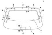
- FIG. 1 is a schematic diagram of a door inner panel 1 according to an embodiment of the present invention.
- FIG. 2 is a sectional view taken along the line II-II of the door inner panel 1 in FIG. 1.
- FIG. FIG. 3 is a sectional view showing a state in which the bracket 101 is attached to the inside of the vehicle of the beam portion 2 of FIG. 2.
- FIG. FIG. 2 is a sectional view taken along the line IV-IV of the door inner panel 1 in FIG. 1.
- FIG. 5 is a sectional view showing a state in which a bracket 111 is attached to the inside of the vehicle of the side frame 3L of FIG. 4.
- FIG. 2 is a sectional view taken along the line VI-VI of the door inner panel 1 in FIG. 1.
- FIG. 7 is a sectional view showing a state in which the bracket 121 is attached to the inside of the vehicle in the lower half portion 4 of FIG. 6.
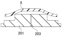
- FIG. FIG. 3 is a diagram showing a state in which a composite material X is placed on a molding fixed mold 201.
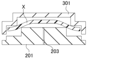
- FIG. FIG. 3 is a diagram showing a state in which the movable molding mold 301 is brought close to the fixed molding mold 201 and the movable molding mold 301 is brought into contact with the composite material X.
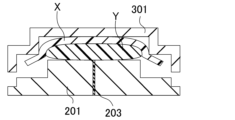
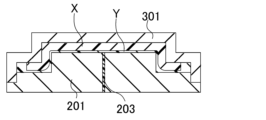
- FIG. 2 is a diagram showing a state in which injection molding material Y is injected into a mold from a gate 203 provided in a fixed mold 201.
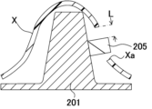
- FIG. 2 is a diagram showing a state in which a composite material X is placed on top of a fixed molding die 201 with a hole forming member 205 inserted into the hole Xa.
- FIG. 2 is a plan view of the fixed molding die 201.
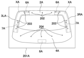
- FIG. 3 is a plan view of a fixed mold 201A according to a second embodiment.
- FIG. 3 is a horizontal sectional view showing a fixed molding mold 201B and a movable molding mold 301B that are provided so as to be openable and closable in the horizontal direction.
- FIG. 4 is a perspective view showing a box-shaped molded body 400.
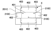
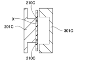
- FIG. 2 is a plan view showing a pattern-cut composite material. It is a front view showing a molding fixed mold 201C in a state where a pattern-cut composite material X is fixed by a fixing member 210C. It is a horizontal cross-sectional view showing a fixed molding mold 201C and a movable molding mold 301C to which a composite material X is fixed by a fixing member 210C.
- [Door inner panel] 1 is a schematic diagram of a door inner panel 1 according to an embodiment of the present invention.
- the door inner panel 1 has a beam portion 2, a pair of side frames 3L, 3R, and a lower half portion 4.
- the pair of side frames 3L, 3R extend upward from the upper left end and upper right end of the lower half portion 4, and the upper ends of the side frames 3L, 3R are connected to each other by the beam portion 2.
- the portion surrounded by the beam portion 2, the side frames 3L, 3R and the lower half portion 4 is a window opening 5.
- the side frames 3L, 3R extend in the vertical direction of the vehicle portion, sandwiching the window opening 5 therebetween, and form a so-called window frame.
- the door inner panel 1 of the present invention is preferably a back door inner panel.
- the back door preferably includes a door inner panel 1 located on the inside of the vehicle, i.e., the front side of the vehicle, and a door outer panel located on the outside of the vehicle, i.e., the rear side of the vehicle.
- the door outer panel may be a resin panel.
- an interior panel may be provided on the vehicle interior side relative to the door inner panel 1 .
- the "back door inner panel” may be simply referred to as the "door inner panel.”
- the back door on which the door inner panel 1 of the present invention is mounted may be, for example, a vertical opening/closing type back door or a left/right opening/closing type back door provided at the rear end of an automobile body.
- the back door is connected to the vehicle body by a hinge so that it can be opened and closed vertically or horizontally.
- a hinge is provided at the upper end of the back door. The hinge allows the back door to swing vertically or horizontally about the hinge to open and close an opening in the vehicle body.
- the door inner panel 1 includes a hinge fastening portion 6 for connection to a hinge.
- the hinge fastening portion 6 is preferably located at the upper end of the door inner panel 1.
- a rod-shaped damper with a built-in spring is attached to both left and right sides of the rear end of the vehicle body, and the other end of the damper is attached to both sides of the inner panel of the back door in the vehicle width direction by a damper stay.
- the damper stay is a fastener for the damper, and the damper prevents the back door from unintentionally closing. It is preferable to provide a damper fastening portion 7 in a portion of the door inner panel 1 to which a damper stay is attached. It is preferable to fix the damper to the door inner panel 1 by fastening and fixing the damper stay to the damper fastening part 7.
- Various functional products may be attached to the door inner panel 1, and spaces for attaching electrical components may be provided.
- functional parts such as door locks, window regulators, inside handles, door armrests, door trim pads, weather strips, and door check link receivers, as well as mounting parts for electrical components such as speakers, electric remote control mirror switches, and power window switches,
- a trunk lock 8 may be mounted on the door inner panel 1. In FIG. 1, a trunk lock 8 is provided at the center of the lower end of the lower half 4.
- the door inner panel 1 of the present invention has a resin panel made of a composite material X and an injection molding material Y as molding materials.
- the composite material X is disposed at least in the side frames 3L and 3R, and the injection molding material Y is integrally molded with the composite material X to form a door inner panel. It is preferable that the center portion of the beam portion 2 and the lower half portion 4 are made of injection molding material Y.
- the composite material X forms the reinforcing portion of the door inner panel 1.
- the mechanical strength of the reinforcing portion is higher than that of the main body formed of the injection molding material Y.
- the door inner panel 1 may include metal fittings 91 to 93 (see FIGS. 2 to 7) that are integrally molded as described later.
- Composite material X includes reinforcing fibers and matrix resin.
- reinforcing fibers are dispersed in the in-plane direction within the matrix resin.
- the manufacturing process can be simplified, and the quality of the obtained molded product (door inner panel 1) can be stabilized.
- the "door inner panel” or the “back door inner panel” may be referred to as a "molded object.”
- a metal fitting 91 may be attached to the door inner panel 1 at the position of the hinge fastening portion 6 . Also, a metal fitting 92 may be attached to the position of the damper fastening portion 7.
- the above metal fitting may be provided integrally with the resin panel of the back door inner panel 1 by insert molding. Insert molding is a molding method in which resin is poured around a metal fitting inserted into a molding die to integrate the metal fitting and the resin. There is no particular limitation on the insert molding method.
- the cross-sectional shape of the resin panel is not particularly limited. It is preferable that the resin panel has at least one flat surface.
- the cross-sectional shape may be a T-shape, an L-shape, a C-shape, a hat shape, or a three-dimensional shape including these, and may further have an uneven shape (e.g., a rib, a boss, etc.).
- the resin panel has a shape that includes a portion whose cross-sectional shape is hat-shaped.
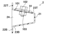
- FIG. 2 is a sectional view taken along the line II-II of the door inner panel 1 in FIG. 1.
- the beam portion 2 includes an inner wall 21 arranged on the inside of the vehicle, outer walls 22T and 22B arranged on the outer side of the vehicle, and a connecting wall 23T connecting the inner wall 21 and the outer wall 22T.
- a connecting wall 23B that connects the inner wall 21 and the outer wall 22B.
- a connecting wall 23T is connected to the upper end of the inner wall 21, and an outer wall 22T is connected to the upper end of the connecting wall 23T.
- a connecting wall 23B is connected to the lower end of the inner wall 21, and an outer wall 22B is connected to the lower end of the connecting wall 23B.
- a metal fitting 91 is provided integrally with the connecting wall 23T. It is preferable that the metal fitting 91 is provided integrally with the connecting wall 23T by insert molding.
- the metal fitting 91 is provided with a bolt insertion hole 91a (bolt insertion portion). Further, it is preferable that holes 23a are provided in the connecting wall 23T at positions corresponding to the bolt insertion holes 91a.
- the beam portion 2 may further include a rib 24 that connects the connecting walls 23T and 23B. It is preferable that the rib 24 be provided within a distance of 30 mm from the metal fitting 91. On the other hand, the rib 24 may be provided at a position more than 30 mm away from the metal fitting 91.
- the ribs 24 may be provided using the composite material X, or the ribs 44 may be provided using the injection molding material Y.
- FIG. 3 is a sectional view showing a state in which the bracket 101 is attached to the inside of the vehicle of the beam portion 2 of FIG.
- the bracket 101 is attached to the beam portion 2 by inserting the bolt 102 through the metal fitting 91 and the bracket 101 and fastening the nut 103 to the bolt 102.
- the hinge can be attached to the door inner panel 1.
- the bolt 102 it is preferable that the bolt 102 be inserted into the bracket 101 and the metal fitting 91 from inside the vehicle, and fastened to the nut 103 on the outside of the vehicle. Strength can be ensured by using the metal fittings 91 in the portion connected to the hinge.
- the bracket 101 makes surface contact only with the metal fitting 91 and not with the resin panel. Only the metal parts of the metal fitting 91 and the bracket 101 come into surface contact with each other, thereby improving the stability of the fastening.
- the area S1 of the contact surface of the bracket 101 with the metal fitting 91 is preferably smaller than the area S2 of the portion of the metal fitting 91 exposed from the resin panel.
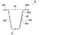
- FIG. 4 is a sectional view taken along the line IV-IV of the door inner panel 1 shown in FIG.
- the side frame 3L includes an inner wall 31 arranged on the inside of the vehicle, outer walls 32R, 32L arranged on the outer side of the vehicle, and a connecting wall 33R connecting the inner wall 31 and the outer wall 32R.
- a connecting wall 33L that connects the inner wall 31 and the outer wall 32L.
- a connecting wall 33R is connected to the right end of the inner wall 31, and an outer wall 32R is connected to the right end of the connecting wall 33R.
- a connecting wall 33L is connected to the left end of the inner wall 31, and an outer wall 32L is connected to the left end of the connecting wall 33L.
- FIG. 4 is a sectional view taken along the line IV-IV of the door inner panel 1 shown in FIG.
- the side frame 3L includes an inner wall 31 arranged on the inside of the vehicle, outer walls 32R, 32L arranged on the outer side of the vehicle, and a connecting wall 33R connecting
- a metal fitting 92 is provided integrally with the connecting wall 33R. It is preferable that the metal fitting 92 is provided integrally with the connecting wall 33R by insert molding.
- the metal fitting 92 is provided with a bolt insertion hole 92a (bolt insertion portion). Moreover, it is preferable to provide the hole 33a in the connection wall 33R at a position corresponding to the bolt insertion hole 92a.
- the side frame 3L may further include a rib 34 that connects the connecting walls 33R and 33L. It is preferable that the rib 34 be provided within a distance of 30 mm from the metal fitting 92. On the other hand, the rib 34 may be provided at a position more than 30 mm away from the metal fitting 92.
- the ribs 34 may be provided using the composite material X, or may be provided using the injection molding material Y.
- FIG. 5 is a sectional view showing a state in which the bracket 111 is attached to the inside of the vehicle of the side frame 3L of FIG. 4.
- the bolt 112 is inserted through the metal fitting 92 and the bracket 111, and the nut 113 is fastened to the bolt 112, thereby attaching the bracket 111 to the side frame 3L.
- the damper By attaching the damper stay to the bracket 111, the damper can be attached to the door inner panel 1.
- the bolt 112 is inserted into the bracket 111 and the metal fitting 92 from inside the vehicle, and fastened to the nut 113 on the outside of the vehicle. Strength can be ensured by using the metal fittings 92 in the portion connected to the damper.
- the bracket 111 makes surface contact only with the metal fitting 92 and not with the resin panel. Only the metal parts of the metal fitting 92 and the bracket 111 come into surface contact with each other, thereby improving the stability of the fastening.
- the area S1 of the contact surface of the bracket 111 with the metal fitting 92 is preferably smaller than the area S2 of the portion of the metal fitting 92 exposed from the resin panel.
- the side frame 3R has a substantially bilaterally symmetrical shape with the side frame 3L, so illustration of the cross-sectional shape is omitted.
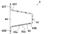
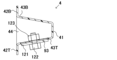
- FIG. 6 is a sectional view taken along the line VI-VI of the door inner panel 1 in FIG. 1.
- the lower half 4 includes an inner wall 41 arranged inside the vehicle, outer walls 42T and 42B arranged outside the vehicle, and a connecting wall connecting the inner wall 41 and the outer wall 42T. 43T, and a connecting wall 43B that connects the inner wall 41 and the outer wall 42B.
- a connecting wall 43T is connected to the upper end of the inner wall 41, and an outer wall 42T is connected to the upper end of the connecting wall 43T.
- a connecting wall 43B is connected to the lower end of the inner wall 41, and an outer wall 42B is connected to the lower end of the connecting wall 43B.
- a metal fitting 93 is provided integrally with the connecting wall 43B. It is preferable that the metal fitting 93 is provided integrally with the connecting wall 43B by insert molding.
- the metal fitting 93 is provided with a bolt insertion hole 93a (bolt insertion portion). Further, it is preferable that holes 43a are provided in the connecting wall 43B at positions corresponding to the bolt insertion holes 93a.
- the lower half 4 may further include a rib 44 that connects the connecting walls 43T and 43B. It is preferable that the rib 44 be provided within a distance of 30 mm from the metal fitting 93. On the other hand, the rib 44 may be provided at a position more than 30 mm away from the metal fitting 93.
- the ribs 44 may be provided using composite material X, or may be provided using injection molding material Y.
- FIG. 7 is a sectional view showing a state in which the bracket 121 is attached to the inside of the vehicle in the lower half 4 of FIG.
- the bracket 121 is attached to the lower half portion 4 by inserting the bolt 122 through the metal fitting 93 and the bracket 121 and fastening the nut 123 to the bolt 122.
- the trunk lock 8 By attaching the trunk lock 8 to the bracket 121, the trunk lock 8 can be attached to the door inner panel 1.
- the bolt 122 is inserted into the bracket 121 and the metal fitting 93 from inside the vehicle, and fastened to the nut 123 on the outside of the vehicle.
- strength can be ensured.
- the bracket 121 makes surface contact only with the metal fitting 93 and not with the resin panel. Only the metal parts of the metal fitting 93 and the bracket 121 come into surface contact with each other, thereby improving the stability of the fastening.
- the area S1 of the contact surface of the bracket 121 with the metal fitting 93 is preferably smaller than the area S2 of the portion of the metal fitting 93 exposed from the resin panel.
- the resin panel of the door inner panel 1 may include an uneven thickness portion. That is, the resin panel may include a structure with uneven thickness.
- the thickness of the resin panel in the parts corresponding to the hinge fastening part 6, the damper fastening part 7, and the trunk lock 8 may be thicker than the thickness of the resin panel in other parts of the back door inner panel 1.
- the uneven thickness of the door inner panel is preferably within 30 mm from the metal fittings 91 to 93. In other words, the periphery of the metal fittings 91 to 93 may have an uneven thickness structure.
- the metal fittings 91 to 93 are covered by the Y part, it is preferable to provide an uneven thickness structure in which a portion within 30 mm from the metal fittings 91 to 93 is thicker than other parts depending on the thickness of the X part and the thickness of the Y part. . It is more preferable that the uneven thickness of the back door inner panel exists within 20 mm from the metal fittings 91 to 93. On the other hand, uneven thickness portions may exist at positions more than 30 mm away from the metal fittings 91 to 93.
- the Y section contributes to the uneven thickness structure. This is because it is preferable that the composite material X used to create the X section is plate-shaped, and it is also preferable that the injection molding material Y is used to create the Y section that is not plate-shaped. By using injection molding material Y, it is easy to manufacture a back door inner panel with uneven thickness structure.
- an uneven thickness structure in which the thickness gradually increases from 2 mm to 3 mm
- a 1 mm thick composite material By adding , an uneven thickness structure can be formed.
- the X portion can contribute to the uneven thickness structure.
- the reinforcing fiber is preferably at least one selected from the group consisting of carbon fiber, aramid fiber, and glass fiber. More preferably, the reinforcing fibers are carbon fibers or glass fibers. More specifically, the reinforcing fibers contained in the composite material X are preferably carbon fibers or glass fibers. The reinforcing fibers contained in the injection molding material Y are preferably carbon fibers or glass fibers.
- Carbon fibers in general The carbon fibers used in the present invention are generally polyacrylonitrile (PAN)-based carbon fibers, petroleum/coal pitch-based carbon fibers, rayon-based carbon fibers, cellulose-based carbon fibers, lignin-based carbon fibers, and phenol-based carbon fibers. Although carbon fibers and the like are known, any of these carbon fibers can be suitably used in the present invention. Among these, polyacrylonitrile (PAN)-based carbon fibers are preferably used in the present invention because of their excellent tensile strength. As the PAN-based carbon fiber, for example, carbon fiber "Tenax" (registered trademark) STS40-24KS (average fiber diameter 7 ⁇ m) manufactured by Teijin Ltd. can be used.
- PAN polyacrylonitrile
- STS40-24KS average fiber diameter 7 ⁇ m
- the carbon fibers used in the present invention may have a sizing agent attached to their surfaces.
- the type of sizing agent can be selected as appropriate depending on the type of carbon fiber and the type of resin used for composite material X or injection molding material Y. and is not particularly limited.
- Glass fiber The case where the reinforcing fiber used in the present invention is glass fiber will be explained.
- the glass fibers used in the present invention may be any glass fibers that are generally referred to as glass fibers. There is no particular limitation on the glass composition such as A glass, C glass, E glass, etc. specified in JIS R3140:2006, and even if it contains components such as TiO 2 , SO 3 , P 2 O 5 , etc. good.
- As the glass fiber for example, glass fiber E-glass RS240QR-483 (count: 2400 g/1000 m) manufactured by Nittobo Co., Ltd. can be used.
- the glass fiber used in the present invention may have a sizing agent attached to its surface.
- the type of sizing agent can be appropriately selected depending on the type of glass fiber and the type of resin, and is not particularly limited. Glass fibers that have been previously treated with a conventionally known coupling agent such as an organic silane compound, an organic titanium compound, an organic borane compound, or an epoxy compound can be preferably used.
- the reinforcing fibers contained in the composite material X of the present invention are dispersed in the in-plane direction.
- the reinforcing fibers are dispersed so that the fiber axes of the reinforcing fibers are oriented in the in-plane direction. It is preferable that the angle between the fiber axis of the reinforcing fiber and the in-plane direction is 45° or less.
- the composite material X is preferably a plate-shaped material.
- the in-plane direction is any direction parallel to a plane orthogonal to the thickness direction of the composite material X.
- the reinforcing fibers are randomly distributed in two-dimensional directions in the plane of the composite material X.
- the composite material preferably two-dimensionally randomly distributed in the in-plane direction.
- being two-dimensionally randomly dispersed means that the reinforcing fibers are oriented randomly in the in-plane direction of the composite material X or the This refers to the state in which the sheet is placed within the sheet surface without showing any directionality.
- the composite material X (or the X part of the molded article) obtained using the two-dimensionally randomly dispersed discontinuous fibers has no in-plane anisotropy and is substantially isotropic.
- the degree of two-dimensional random orientation is evaluated by determining the ratio of tensile modulus in two directions perpendicular to each other.
- the (E ⁇ ) ratio of the larger tensile modulus measured in any direction of the composite material (or the X part of the molded body) and the direction perpendicular thereto is 5 or less, If it is preferably 2 or less, more preferably 1.5 or less, it can be evaluated that the reinforcing fibers are two-dimensionally randomly dispersed.
- the method for evaluating two-dimensional random dispersion in the in-plane direction is to heat the door inner panel 1 to a temperature higher than its softening temperature, return it to a flat plate shape, and then take out only the X portion. It is best to solidify it after washing. Thereafter, when a test piece is cut out from the X part that has been returned to the flat plate shape and the tensile modulus is determined, the random dispersion state in the two-dimensional direction can be confirmed.
- the composite material X contains reinforcing fibers A having a weight average fiber length LwA. Since the weight average fiber length of composite material X does not change before and after molding, by examining the weight average fiber length of the reinforcing fibers included in part X, the weight average fiber length LwA of the reinforcing fibers contained in composite material X can be found.
- the weight average fiber length of the reinforcing fibers A contained in the X part is preferably 1 mm or more, more preferably 3 mm or more.
- the weight average fiber length of the reinforcing fibers A included in the X part is more preferably 3 mm or more and 100 mm or less.
- the weight average fiber length LwA of the reinforcing fibers A is more preferably 3 mm or more and 80 mm or less, and even more preferably 5 mm or more and 60 mm or less. If LwA is 100 mm or less, the fluidity of the material is less likely to decrease when the composite material X is manufactured by press molding, and it is easier to create a fiber-reinforced resin member in a desired shape. Moreover, when LwA is 1 mm or more, the mechanical strength of the obtained fiber-reinforced resin member is less likely to decrease, which is preferable.
- the weight average fiber length and number average fiber length of the reinforcing fibers are determined by equations (1) and (2) described below.
- the injection molding material Y contains reinforcing fibers B having a weight average fiber length LwB, and it is preferable that LwB ⁇ LwA.
- LwB weight average fiber length
- the composite material X forms both side frames extending in the vertical direction of the window opening. This region is generally narrower than other parts and requires higher strength than other parts (for example, parts made only of injection molding material Y).
- the injection molding material Y is the one immediately before injection, and if there is a kneading step before injection, the one after kneading is used. It is called injection molding material Y. Since the weight average fiber length does not change after kneading, the weight average fiber length LwB of the reinforcing fibers contained in the injection molding material Y can be found by examining the weight average fiber length of the reinforcing fibers contained in the Y part. It is preferable that the weight average fiber length LwB of the reinforcing fibers B is less than 3 mm.
- the weight average fiber length LwB is more preferably 0.01 mm or more and less than 3 mm.
- the lower limit is preferably 0.01 mm or more, more preferably 0.05 mm or more, and even more preferably 0.1 mm or more. Mechanical strength is ensured when the weight average fiber length LwB is 0.01 mm or more.
- the upper limit of the weight average fiber length LwB is preferably less than 3 mm, more preferably less than 2 mm, and even more preferably less than 1 mm. When the weight average fiber length LwB is 1.0 mm or less, it is easy to manufacture the injection molding material Y by kneading.
- the weight average fiber length of the reinforcing fibers after a sufficient kneading process is generally less than 1 mm.
- the weight average fiber length and number average fiber length of the reinforcing fibers are determined by equations (1) and (2) described below.
- the number average fiber length Ln and the weight average fiber length Lw can be calculated by the following formulas (1) and (2).
- the units of the number average fiber length Ln and the weight average fiber length Lw are mm.
- the reinforcing fibers can be extracted from the door inner panel by, for example, performing a heat treatment at 500°C for about 1 hour and removing the resin in a furnace.
- the number average fiber length Ln and weight average fiber length Lw can be calculated in the same manner as in the above formulas (1) and (2).
- the reinforcing fiber volume ratio (Vf) can be determined by the following formula (3). There is no particular limitation on the reinforcing fiber volume ratio, but the reinforcing fiber volume ratio (Vf) is preferably 10 to 60 Vol%, more preferably 20 to 50 Vol%, and even more preferably 25 to 45 Vol%. .
- Reinforcement fiber volume ratio (Vf) 100 ⁇ Reinforcement fiber volume / (Reinforcement fiber volume + resin volume) Formula (3)
- Vfa 100 ⁇ Reinforcement fiber volume / (Reinforcement fiber volume + resin volume)
- Vfa is preferably 20 to 45 Vol%, more preferably 25 to 40 Vol%.
- Vfb is preferably 1 to 40 Vol%, more preferably 5 to 30 Vol%, even more preferably 10 to 25 Vol%.
- the matrix resin contained in the composite material X and the resin contained in the injection molding material Y may be thermosetting or thermoplastic.
- thermoplastic resin its type is not particularly limited, and one having a desired softening point or melting point can be appropriately selected and used.
- thermoplastic resin those having a softening point within the range of 180°C to 350°C are usually used, but the thermoplastic resin is not limited thereto.
- Thermoplastic resins include polyolefin resins, polystyrene resins, polyamide resins, polyester resins, polyacetal resins (polyoxymethylene resins), polycarbonate resins, (meth)acrylic resins, polyarylate resins, polyphenylene ether resins, polyimide resins, polyether nitrile resins, phenoxy resins, polyphenylene sulfide resins, polysulfone resins, polyketone resins, polyether ketone resins, thermoplastic urethane resins, fluorine-based resins, and thermoplastic polybenzimidazole resins.
- thermoplastic resin Only one type of thermoplastic resin may be used for the resin panel of the door inner panel 1 of the present invention, or two or more types may be used. Examples of embodiments in which two or more types of thermoplastic resins are used together include embodiments in which thermoplastic resins having mutually different softening points or melting points are used together, and embodiments in which thermoplastic resins having mutually different average molecular weights are used in combination, etc. It is possible, but not limited to this. When using a thermoplastic resin, it is more preferable to use a polyolefin resin, and even more preferable to use a polypropylene resin.
- the resin contained in the injection molding material Y is preferably a thermoplastic resin.
- the resin contained in the X part is a thermoplastic resin, it is more preferable that the resins contained in the composite material X and the injection molding material Y are the same type of thermoplastic resin.
- Thermosetting resin contained in the composite material X may be a thermosetting resin.
- the composite material X may be a sheet molding compound using reinforcing fibers. Due to its high moldability, sheet molding compounds can be easily molded into even complex shapes. Sheet molding compounds have higher fluidity and shapeability than continuous fibers, Ribs and bosses can be easily created.
- the resin used in the composite material may contain additives such as a mold release agent, a pigment, a softener, a plasticizer, a surfactant, and the like.
- the reinforcing fiber A contained in the composite material X is glass fiber and/or carbon fiber
- the reinforcing fiber B contained in the injection molding material Y is glass fiber.
- Carbon fiber may be used partially as the reinforcing fiber A contained in the composite material X
- glass fiber may be used in the portion other than the portion using carbon fiber.
- the portion using carbon fiber is preferably the periphery of the hole Xa described later, and is preferably used to reinforce fastening.
- the resin contained in the composite material X may be a thermoplastic resin or a thermosetting resin
- the resin contained in the injection molding material Y may be a thermoplastic resin or a thermosetting resin. While the injection molding material Y includes a thermoplastic resin, the composite material X may be a thermosetting sheet molding compound.
- Va:Vb is preferably 10:90 to 50:50, more preferably 20:80 to 40:60.
- Va:Vb is 10:90 to 50:50, both side frames 3L and 3R extending in the vertical direction of the window opening 5 are formed using the composite material
- the door inner panel 1 can be formed using the molding material Y.
- the composite material X preferably forms part X.
- the injection molding material Y preferably forms a Y section.
- the door inner panel 1 of the present invention has a skin layer on the inside of the vehicle and a skin layer on the outside of the vehicle.
- the skin layer is a layer formed by cooling and solidifying the molding material (composite material X, injection molding material Y) by contacting the cavity wall surface of the molding die.
- composite material X composite material X
- injection molding material Y injection molding material Y
- the reinforcing fibers are dispersed in the in-plane direction, so when the composite material X becomes the X section, the reinforcing fibers dispersed in the in-plane direction are observed, giving a beautiful design surface.
- the skin layer having the X portion be provided on the surface of the door inner panel 1 that faces inside the vehicle. More preferably, the surfaces of the side frames 3L and 3R extending in the vertical direction of the window opening 5, which are on the inside of the vehicle, become an interior design part when the vehicle is installed. It is even more preferable that the shape of the grain provided on the inner wall surface of the cavity of the movable molding mold or the fixed molding mold be transferred to the interior design portion.
- the surfaces other than the surfaces of the side frames 3L and 3R that are located on the inside of the vehicle and that are formed by the Y section may be covered with an interior panel.
- the single-sided skin layer on which the X portion is observed may be the surface of the door inner panel 1 on the outside of the vehicle.
- most of the skin layer on the inside of the vehicle of the door inner panel 1 becomes the Y portion, so that the appearance of the door inner panel 1 viewed from the inside of the vehicle can be given a sense of unity.
- the door inner panel 1 is manufactured by using a plate-shaped composite material X and by flowing an injection molding material Y in the in-plane direction of the composite material X to extend the surface.
- the manufacturing method for manufacturing the door inner panel 1 by press molding includes the following steps (1) to (4): (1) Step of placing the composite material X in the cavity of the fixed mold; (2) The step of bringing the movable molding mold close to the fixed molding mold and bringing the movable molding mold into contact with the composite material X; (3) Injecting the injection molding material Y into the mold; (4) A step of integrally molding the door inner panel 1 by pressing the composite material X and the injection molding material Y in a mold.
- the resin contained in the composite material X and the injection molding material Y is a thermoplastic resin
- cold press molding will be mainly described below, the composite material X and the injection molding material Y may be integrally molded by hot press molding.
- the manufacturing method for manufacturing the door inner panel 1 by cold press molding includes the following steps (0) to (4): (0) heating the composite material X to a first predetermined temperature; (1) Step of placing the composite material X in the cavity of the fixed mold; (2) The step of bringing the movable molding mold close to the fixed molding mold and bringing the movable molding mold into contact with the composite material X; (3) Injecting the injection molding material Y into the mold; (4) A step of integrally molding the door inner panel 1 by pressing the composite material X and the injection molding material Y in a mold.
- the composite material X is heated to the first predetermined temperature in advance.
- the first predetermined temperature is a temperature higher than the melting point and lower than the decomposition temperature of the thermoplastic resin.
- the first predetermined temperature is a temperature higher than the glass transition temperature and lower than the decomposition temperature of the thermoplastic resin.
- Step of placing the composite material X in the cavity of the fixed mold mold As shown in FIG. 8, the composite material X is placed on the fixed mold mold 201.
- the door inner panel is a back door inner panel
- at least one composite material X is placed at positions corresponding to both side frames 3L and 3R.
- the step of arranging the composite material X on the fixed mold can be performed using a conventionally known method. Note that the composite material X may be pre-shaped and placed in a fixed mold so as to follow the mold.
- the temperature of the fixed mold 201 is adjusted to a second predetermined temperature.
- the second predetermined temperature is a temperature below the melting point of the thermoplastic resin.
- the second predetermined temperature is a temperature lower than the glass transition temperature of the thermoplastic resin.
- the injection molding material Y is injected into the mold from the gate 203 provided in the fixed mold 201.
- the injection molding material Y may be injected immediately before or after pressure starts to be applied to a portion of the composite material X from the movable mold 301.
- the method for injecting the injection molding material Y into the mold is not particularly limited, and any conventionally known method can be used.
- the composite material X is pressed against the movable mold 301 by the pressure of the injection molding material Y.
- the injection molding material Y is kneaded, and it is preferable to provide a clearance between the fixed molding mold 201 and the movable molding mold 301 to fill the molding material with the injection material.
- By pressing the injection molding material Y after filling it into the mold it is possible to suppress the displacement of the composite material X.
- the injection molding material Y is put into the mold, if the thermoplastic resin contained in the injection molding material Y is crystalline, the temperature should be higher than the melting point of the thermoplastic resin and lower than the decomposition temperature, and if the thermoplastic resin is amorphous, the injection molding material Y should be is preferably heated to a temperature above the glass transition temperature and below the decomposition temperature of the thermoplastic resin.
- the position where the movable molding mold is stopped is preferably after the movable molding mold 301 contacts the composite material X.
- the molding pressure is not particularly limited, but is preferably less than 20 MPa, more preferably 10 MPa or less relative to the projected area of the cavity of the mold.
- the composite material X is cooled by contacting the cavity wall surface of the movable mold 301, so that the X portion where the composite material X is solidified forms a part of the skin layer. Note that when the shape of the grain is provided on the cavity wall surface of the fixed molding mold 201 or the movable molding mold 301, the shape of the grain is transferred to the skin layer of the door inner panel 1.
- the composite material X forms the X part
- the injection molding material Y forms the Y part
- the X part and the Y part constitute the door inner panel 1.
- the integrally molded door inner panel 1 is taken out from the mold.
- the bonding strength between the X part and the Y part is excellent.
- the easily flowable injection molding material Y is injected and pressed while the plate-shaped composite material X is placed in the mold, it is possible to manufacture door inner panels with complex shapes including ribs and bosses. can. Note that various steps may be added between steps (0) to (4) above. Further, vacuum press molding may be performed in which the above steps are performed under vacuum.
- the door inner panel 1 may also be manufactured using hot press molding. In this case, step (0) is unnecessary.
- the mold may be set at the curing temperature of the SMC.
- the portion Y is covered by the portion Y.
- the metal fittings 91 to 93 are placed in a mold in advance, and an injection molding material Y is injected into the mold, so that the injection molding material Y covers the metal fittings 91 to 93, and after molding, the metal fittings 91 to 93 are covered by the portion Y.
- the portion X is molded integrally with the metal fittings 91 to 93 via the portion Y.
- the X portion does not contact at least one of the metal fittings 91 to 93.
- the composite material Bye.
- the metal fittings 91 to 93 are covered by the Y portion.
- This manufacturing method leads to a reduction in manufacturing man-hours.
- welds caused by contact between the composite material X and the injection molding material Y do not exist around the metal fasteners. Become.
- the metal fittings 91 to 93 be covered by the Y portion and that there is no weld caused by the Y portion on the contact surface with the metal fittings 91 to 93. Note that if the X section is not in contact with the metal fittings 91 to 93, it is preferable that it is in contact with the Y section.
- holes 23a, 33a, 43a are provided at positions corresponding to the bolt insertion holes 91a to 93a of the resin panel into which metal fittings 91 to 93 are insert molded.
- holes Xa may be provided in advance prior to step (1) at positions corresponding to holes 23a, 33a, 43a in the composite material X.
- Holes 23a, 33a, 43a can be created in the X portion by providing a hole-forming member in the molding die at a position corresponding to hole Xa in the composite material X, inserting the hole-forming member into hole Xa in the composite material X, and then completing molding of the composite material X.
- a hole forming member for forming holes Xa in the composite material X is provided in at least one of the fixed molding mold or the movable molding mold, In a step before step (1), holes Xa are provided in the composite material X, In step (1), it is preferable that the composite material X is placed in the mold with the hole forming member inserted into the hole Xa.
- the hole forming member 205 is provided in the fixed mold 201, and the composite material X is placed on the upper part of the fixed mold 201 with the hole forming member 205 inserted into the hole Xa.
- the hole forming member 205 is provided by placing a pin in the fixed mold 201, and is sometimes called a core pin. Note that the projected area of the hole Xa is larger than the projected area of the hole forming member 205. Thereafter, by performing steps (2) to (4), the door inner panel 1 can be molded while preventing the composite material X from shifting during molding. Note that as the hole Xa provided in the composite material X, holes other than the holes 23a, 33a, and 43a corresponding to the bolt insertion holes 91a to 93a may be provided.
- the hole Xa is sufficiently large, the injection molding material Y will pass through the hole Xa. For this reason, when providing a skin layer including the Y portion on both sides of the door inner panel 1, it is preferable that the hole Xa is sufficiently large.
- the mold in which the hole forming member 205 is provided may be a male or female mold, but when using the composite material X that has been preheated and is in a softened state, the composite material It is preferable to provide the mold on the side where the material X is placed. Further, depending on the case, the hole-forming member may be provided in both male and female molds so that the end surfaces of the hole-forming member face each other and come into contact with each other during mold clamping.
- the average distance Lf between the inner wall surface of the hole Xa of the composite material X and the hole forming member 205 satisfies 0 ⁇ Lf ⁇ 10t. This means that when the thickness t of the composite material X is large, the flow distance of the composite material X can be increased. For example, when the thickness of the composite material X is 2.5 mm, the average distance Lf may be 0 ⁇ Lf ⁇ 25 mm. The distance between the inner wall surface of the hole Xa of the composite material Lf is the average of L even if the shape of the hole forming member 205 and the hole Xa are irregular or the positions of the holes are uneven.
- holes Xa are provided at the upper and lower parts of the side frames 3L and 3R of the composite material X. It is preferable that the holes Xa are formed at two or more locations in one composite material X. By providing the holes Xa at two or more locations in the composite material X, displacement of the composite material X can be suitably suppressed.
- holes Xa may be provided at positions corresponding to holes 23a and 33a.
- the holes 23a are provided at the upper portions of the side frames 3L and 3R, and the holes 33a are provided at the lower portions.
- the hole Xa may be provided at a different position that does not correspond to the holes 23a and 33a.
- holes may be provided in the Y portion, and the holes 23a, 33a, and 43a may be provided in the door inner panel 1.
- the injection molding material Y in which the injection molding material Y is injected into the mold and put into the mold, if the mold is designed to have holes 23a, 33a, and 43a in advance, the injection molding material Y can be poured and molded. Once completed, holes 23a, 33a, and 43a can be created in the Y section. Further, holes corresponding to the holes 23a, 33a, and 43a may be provided in both the X part and the Y part, or holes may be provided in both the X part and the Y part at positions that do not correspond to the holes 23a, 33a, and 43a. It's okay.
- the holes 23a, 33a, 43a are provided in both the X section and the Y section at the same time as integral molding, the holes 23a, 33a, 43a can be easily provided. If the holes 23a, 33a, and 43a are provided by integral molding, the manufacturing process can be simplified. Note that the holes 23a, 33a, and 43a may be provided by secondary processing after the press forming in (4) is completed.
- FIG. 13 is a plan view of the fixed mold 201.
- the upper surface of the molding fixed mold 201 includes a region 2A corresponding to the shape of the beam portion 2, a region 3LA corresponding to the shape of the side frame 3L, a region 3RA corresponding to the shape of the side frame 3R, and a lower surface.
- a region 4A corresponding to the shape of the half portion 4 is provided.
- a region XA corresponding to the composite material X, a region 6A corresponding to the hinge fastening portion 6, a region 7A corresponding to the damper fastening portion 7, and a region 8A corresponding to the region where the trunk lock 8 is arranged are shown by broken lines.
- the position where the gate for injecting the injection molding material Y is provided is not particularly limited.
- the gate for injecting the injection molding material Y may be provided in areas (2A, 4A) other than the area XA where the composite material X is placed.
- n1 is the number of first gates provided in the region (XA) where the composite material X is placed in a plan view of the mold cavity
- n2 is the number of second gates provided in a region other than the region where the composite material X is placed in a plan view of the cavity of the mold.
- one gate 202 is provided in region 2A, eight gates 203 are provided in region XA, and three gates 204 are provided in region 4A.
- Gate 203 is a first gate provided in region XA, and gates 202 and 204 are second gates provided in a region other than region XA.
- the injection molding material Y injected from the gate 203 presses the composite material X against the inner wall of the cavity of the movable mold, and the injection molding material Y is also applied to areas other than the area XA.
- FIG. 13 describes the case where the fixed molding mold 201 is provided with gates 202 to 204 for injecting the injection molding material Y, it is also possible to provide the gates for injecting the injection molding material Y on the movable mold 301. Good too. Even in this case, by satisfying n1>n2 ⁇ 0, the gap between the composite material X and the cavity wall surface of the molding fixed mold 201 is closed. It is possible to prevent the injection molding material Y from entering in between.
- V1 is the amount of injection molding material Y discharged from the first gate (203) provided in the region (XA) where the composite material X is placed in a plan view of the mold cavity
- V2 is the amount of injection molding material Y discharged from the second gates (202, 204) provided in areas (2A, 4A) other than the area where the composite material X is placed, in a plan view of the mold cavity.
- one gate 202 is provided in region 2A, eight gates 203 are provided in region XA, and three gates are provided in region 4A. .
- V1>V2 ⁇ 0 It is preferable to satisfy the following.
- the injection molding material Y injected from the gate 203 presses the composite material X against the inner wall of the cavity of the movable molding mold, and furthermore, the injection molding material Y spreads to areas other than the area XA.
- the injection molding material Y injected from the gates 202 and 204 is composite. It does not reach the material X, and can be prevented from entering between the material and the wall surface of the cavity of the movable mold.
- the skin layers on both sides of the side frames 3L and 3R may include a Y section at least in part.
- FIG. 14 is a plan view of a molding fixed mold 201A according to the second embodiment. Note that configurations similar to those in FIG. 13 are given the same reference numerals and explanations are omitted.
- n1 is the number of first gates provided in the region (XA) where the composite material X is placed in a plan view of the mold cavity; n2 is the number of second gates provided in a region other than the region where the composite material X is placed in a plan view of the cavity of the mold.
- gate 203 is a first gate provided in region XA
- gates 202 and 204 are second gates provided in a region other than region XA.
- the injection molding material Y injected from the gates 202 and 204 spreads to the area XA where the composite material It can encourage people to get between the two.
- V1 is the amount of injection molding material Y discharged from the first gate provided in the area (XA) where the composite material X is placed in a plan view of the mold cavity
- V2 is the amount of injection molding material Y discharged from the second gate provided in a region other than the region (XA) where composite material X is arranged in a plan view of the mold cavity.
- three gates 202 are provided in region 2A, six gates 203 are provided in region XA, and five gates are provided in region 4A. .
- V1 the total amount of the injection molding material Y discharged from the gate 203
- V2 the total amount of the injection molding material Y discharged from the gates 202 and 204
- 0 ⁇ V1 ⁇ V2 It is preferable to satisfy the following.
- the injection molding material Y injected from the gates 202 and 204 spreads to the area XA where the composite material It can encourage people to get between the two.
- [Opening/closing direction of mold] 1. Vertical direction In the present invention, there is no particular limitation on the opening/closing direction of the mold, but the fixed mold is the lower mold, the movable mold is the upper mold, and the upper mold moves up and down toward the lower mold. This allows the mold to be opened and closed. 2. Horizontal direction On the other hand, the molded body may be manufactured by opening and closing the movable mold by moving the movable mold toward the fixed mold in the horizontal direction.
- FIG. 15 is a horizontal sectional view showing a fixed molding mold 201B and a movable molding mold 301B, which are provided so as to be openable and closable in the horizontal direction.
- a plurality of fixing members 210 are provided to fix the composite material X to the molding fixed mold 201B.
- the plurality of fixing members 210 have different positions in the horizontal direction.
- the fixing member 210 may be provided at different positions in the height direction. Three or more fixing members 210 may be provided at different positions in the height direction and the horizontal direction. Note that a hole 310 into which the fixing member 210 is inserted may be provided at a position facing the fixing member 210 of the movable mold 301B. 3. Fixed mold and movable mold Depending on the mold, the fixed mold may be movable. If the fixed mold moves, the mold that moves a relatively small distance is called the fixed mold, and the mold that moves relatively long distance is called the movable mold.
- the composite material X may have a pattern-cut shape.
- Pattern cutting refers to composite material that is cut in advance into a desired shape to match the shape of the molded object. It is not a simple shape such as a square or rectangle.
- FIG. 17 when manufacturing a box-shaped molded object 400, as shown in FIG. 17, the composite material Good too.
- four side surface portions 402 are provided around a bottom surface portion 401 of a rectangular box, and a margin 403 is provided at the portion to be joined during molding of the adjacent side surface portions 402. There is. Note that in FIG. 17, the margin 403 is provided only on one of the two adjacent side portions 402, but the margin 403 may be provided on both.
- the composite material X has a pattern-cut shape.
- the solidification of the resin starts from the moment the fixed mold comes into contact with the composite material X, so the fluidity during molding is lower than that of a thermosetting resin. Therefore, if the material is cut into the desired shape in advance, it is easier to create a molded object having the desired shape.
- the pattern cut shape is preferably a shape developed by computer-based inverse molding analysis from the three-dimensional shape of the press-formed product to be manufactured.
- FIG. 18 is a front view showing a molding fixed mold 201C in which a pattern-cut composite material X is fixed by a fixing member 210C. As shown in FIG. 18, for example, in a portion 401 that is the bottom surface of a rectangular box, it is preferable to fix the composite material X to the molding fixing mold 201C using fixing members 210C at multiple locations spaced apart in the horizontal direction.
- FIG. 19 is a horizontal sectional view showing a fixed molding mold 201C and a movable molding mold 301C to which the composite material X is fixed by a fixing member 210C.
- the composite material X needs to be arranged so that the plate surface is in the vertical direction (perpendicular to the plane of the paper in FIG. 19).
- the pattern-cut composite material X there is a possibility that the composite material sag in an unintended direction compared to a composite material having a simple shape such as a square or a rectangle.
- the composite material X may be pre-shaped so as to fall toward the molding fixed mold 201C side.
- the step (3) of injecting the injection molding material Y into the mold includes a step of injecting the injection molding material Y between a fixed mold and a movable mold, and the injection molding material Y is injected into the fixed mold. It is preferable to start from Compared to injecting the injection molding material Y from a movable mold, injection from a fixed mold is preferable because the equipment does not become too complicated.
- the design surface is formed by a movable mold. This is because the marks of the injection gate remain on the surface formed by the fixed mold of the molded body, while the marks of the injection gate remain on the surface formed by the movable mold. At this time, the design of the molded article can be improved by making the following modifications to the composite material X or the movable mold.
- a skin layer is formed by filling an injection molding material between the movable mold and the composite material X.
- the thickness of the skin layer is preferably 50 ⁇ m or more and 300 ⁇ m or less, and preferably 70 ⁇ m or more and 200 ⁇ m or less.
- One or more distribution holes X1 are provided for Y to pass through, and the injection molding material Y injected from the gate 203 of the fixed molding mold 201B flows through the distribution holes X1, so that the composite material X and the movable molding mold 301B are combined.
- the injection is performed during the period of time.
- the injection molding material Y injected from the fixed molding mold 201B passes through the flow hole X1, so that the injection molding material Y can enter between the composite material X and the movable molding mold 301B.
- the design surface is formed by a movable mold
- a resin sheet between the composite material X placed in the fixed mold and the movable mold. It is preferable that the resin sheet does not contain fibers, since the transferability of the mirror surface of the molding movable mold is good. Providing the resin sheet makes it easier to form a designed surface on the molded product.
- the resin sheet may be laminated with the composite material X and then placed on the fixed mold, or the resin sheet may be laminated on the composite material X after the composite material X is placed on the fixed mold.
- the design surface of the molded article When the design surface of the molded article is formed by the movable mold, the design surface may have a grain shape formed by the movable mold. By creating a textured shape on the molded body by transferring the mold surface of the movable molding mold, the reinforcing fibers contained in the composite material can be made less noticeable, improving the design.
- a resin-rich layer may be provided on the surface of the composite material X so that the grain shape on the mold surface of the movable mold is easily transferred to the composite material X, and when placing the composite material X on the fixed mold, the movable mold A resin sheet may be placed between the mold and the composite material X.
- Door inner panel 2 Beam parts 3L, 3R: Side frame 4: Lower half 5: Window opening 6: Hinge fastening part 7: Damper fastening part 8: Trunk lock 91, 92, 93: Metal fittings 201, 201A , 201B, 201C: Fixed molding mold 202, 203, 204: Gate 205: Hole forming member 210, 210C: Fixed member 301, 301B, 301C: Movable molding mold
Landscapes
- Engineering & Computer Science (AREA)
- Mechanical Engineering (AREA)
- Manufacturing & Machinery (AREA)
- Chemical & Material Sciences (AREA)
- Composite Materials (AREA)
- Textile Engineering (AREA)
- Injection Moulding Of Plastics Or The Like (AREA)
- Casting Or Compression Moulding Of Plastics Or The Like (AREA)
- Moulds For Moulding Plastics Or The Like (AREA)
Priority Applications (4)
| Application Number | Priority Date | Filing Date | Title |
|---|---|---|---|
| CN202380067529.2A CN119894701A (zh) | 2022-09-20 | 2023-07-31 | 车门内面板的制造方法以及车门内面板 |
| EP23867898.1A EP4592111A4 (en) | 2022-09-20 | 2023-07-31 | METHOD FOR MANUFACTURING DOOR INTERNAL PANELS AND DOOR INTERNAL PANELS |
| JP2024548114A JP7804779B2 (ja) | 2022-09-20 | 2023-07-31 | ドアインナパネルの製造方法およびドアインナパネル |
| US19/112,069 US20260084351A1 (en) | 2022-09-20 | 2023-07-31 | Door inner panel manufacturing method, and door inner panel |
Applications Claiming Priority (4)
| Application Number | Priority Date | Filing Date | Title |
|---|---|---|---|
| JP2022149322 | 2022-09-20 | ||
| JP2022-149322 | 2022-09-20 | ||
| JP2022196925 | 2022-12-09 | ||
| JP2022-196925 | 2022-12-09 |
Publications (1)
| Publication Number | Publication Date |
|---|---|
| WO2024062772A1 true WO2024062772A1 (ja) | 2024-03-28 |
Family
ID=90454465
Family Applications (2)
| Application Number | Title | Priority Date | Filing Date |
|---|---|---|---|
| PCT/JP2023/027973 Ceased WO2024062772A1 (ja) | 2022-09-20 | 2023-07-31 | ドアインナパネルの製造方法およびドアインナパネル |
| PCT/JP2023/027974 Ceased WO2024062773A1 (ja) | 2022-09-20 | 2023-07-31 | 成形体の製造方法 |
Family Applications After (1)
| Application Number | Title | Priority Date | Filing Date |
|---|---|---|---|
| PCT/JP2023/027974 Ceased WO2024062773A1 (ja) | 2022-09-20 | 2023-07-31 | 成形体の製造方法 |
Country Status (5)
| Country | Link |
|---|---|
| US (1) | US20260084351A1 (cg-RX-API-DMAC7.html) |
| EP (2) | EP4592112A4 (cg-RX-API-DMAC7.html) |
| JP (2) | JP7804779B2 (cg-RX-API-DMAC7.html) |
| CN (2) | CN119894701A (cg-RX-API-DMAC7.html) |
| WO (2) | WO2024062772A1 (cg-RX-API-DMAC7.html) |
Families Citing this family (1)
| Publication number | Priority date | Publication date | Assignee | Title |
|---|---|---|---|---|
| CN121946893B (zh) * | 2026-04-02 | 2026-06-12 | 福建省睿步智能装备有限公司 | 一种碳纤维复合件模压工作站及其模压方法 |
Citations (10)
| Publication number | Priority date | Publication date | Assignee | Title |
|---|---|---|---|---|
| JPH0315509A (ja) * | 1989-06-14 | 1991-01-23 | Kasai Kogyo Co Ltd | 自動車内装用芯材の製造方法 |
| JPH06144123A (ja) * | 1992-11-10 | 1994-05-24 | Kasai Kogyo Co Ltd | 自動車用内装部品およびその製造方法 |
| JP2001138356A (ja) * | 1999-11-17 | 2001-05-22 | Kasai Kogyo Co Ltd | 部分表皮貼り樹脂成形体の成形方法並びに成形装置 |
| JP2002137249A (ja) * | 2000-11-07 | 2002-05-14 | Sumitomo Chem Co Ltd | 部分表皮貼り樹脂成形体の成形方法並びに成形用金型 |
| JP2005059632A (ja) * | 2003-08-19 | 2005-03-10 | Kasai Kogyo Co Ltd | 自動車用内装部品及びその製造方法 |
| WO2015091448A1 (en) | 2013-12-19 | 2015-06-25 | Compagnie Plastic Omnium | Structural component for motor vehicle part and motor vehicle part including the component |
| JP2019010910A (ja) | 2017-06-29 | 2019-01-24 | ダイキョーニシカワ株式会社 | 車両用外装パネル及びその製造方法 |
| WO2020196076A1 (ja) | 2019-03-28 | 2020-10-01 | 帝人株式会社 | プレス成形体の製造方法 |
| JP2020179549A (ja) | 2019-04-24 | 2020-11-05 | 日立化成株式会社 | 樹脂成形品の製造方法 |
| JP2022149322A (ja) | 2021-03-25 | 2022-10-06 | 積水化学工業株式会社 | 封止部材及び升 |
Family Cites Families (9)
| Publication number | Priority date | Publication date | Assignee | Title |
|---|---|---|---|---|
| US5166237A (en) * | 1989-04-20 | 1992-11-24 | Sumitomo Chemical Company, Ltd. | Thermoplastic resin composition |
| AT404690B (de) * | 1995-03-08 | 1999-01-25 | Magna Eybl Gmbh | Verfahren zur herstellung von verkleidungsteilen aus faserverbundmatten sowie nach dem verfahren hergestellte verkleidungsteile |
| JPH09117922A (ja) | 1995-10-24 | 1997-05-06 | Ikeda Bussan Co Ltd | スタンピング成形型 |
| JP3413356B2 (ja) | 1997-12-25 | 2003-06-03 | 住友化学工業株式会社 | 多層成形品の製造に用いる金型装置 |
| JP5157369B2 (ja) * | 2007-11-02 | 2013-03-06 | トヨタ紡織株式会社 | トリム材 |
| JP2012106490A (ja) * | 2010-10-19 | 2012-06-07 | Toray Ind Inc | 複合成形体の製造方法および装置 |
| JP5855401B2 (ja) | 2011-09-21 | 2016-02-09 | 三菱レイヨン株式会社 | 繊維強化熱可塑性樹脂成形品の製造方法 |
| KR20160132294A (ko) * | 2015-05-08 | 2016-11-17 | (주)엘지하우시스 | 섬유강화복합소재를 이용한 인서트 사출 성형 방법 및 이를 이용한 사출 성형품 |
| US10710286B2 (en) * | 2016-02-19 | 2020-07-14 | Nyx, Inc. | In-mold carpet lamination |
-
2023
- 2023-07-31 WO PCT/JP2023/027973 patent/WO2024062772A1/ja not_active Ceased
- 2023-07-31 JP JP2024548114A patent/JP7804779B2/ja active Active
- 2023-07-31 EP EP23867899.9A patent/EP4592112A4/en active Pending
- 2023-07-31 WO PCT/JP2023/027974 patent/WO2024062773A1/ja not_active Ceased
- 2023-07-31 CN CN202380067529.2A patent/CN119894701A/zh active Pending
- 2023-07-31 CN CN202380063439.6A patent/CN119836359A/zh active Pending
- 2023-07-31 US US19/112,069 patent/US20260084351A1/en active Pending
- 2023-07-31 JP JP2024548115A patent/JP7745108B2/ja active Active
- 2023-07-31 EP EP23867898.1A patent/EP4592111A4/en active Pending
Patent Citations (10)
| Publication number | Priority date | Publication date | Assignee | Title |
|---|---|---|---|---|
| JPH0315509A (ja) * | 1989-06-14 | 1991-01-23 | Kasai Kogyo Co Ltd | 自動車内装用芯材の製造方法 |
| JPH06144123A (ja) * | 1992-11-10 | 1994-05-24 | Kasai Kogyo Co Ltd | 自動車用内装部品およびその製造方法 |
| JP2001138356A (ja) * | 1999-11-17 | 2001-05-22 | Kasai Kogyo Co Ltd | 部分表皮貼り樹脂成形体の成形方法並びに成形装置 |
| JP2002137249A (ja) * | 2000-11-07 | 2002-05-14 | Sumitomo Chem Co Ltd | 部分表皮貼り樹脂成形体の成形方法並びに成形用金型 |
| JP2005059632A (ja) * | 2003-08-19 | 2005-03-10 | Kasai Kogyo Co Ltd | 自動車用内装部品及びその製造方法 |
| WO2015091448A1 (en) | 2013-12-19 | 2015-06-25 | Compagnie Plastic Omnium | Structural component for motor vehicle part and motor vehicle part including the component |
| JP2019010910A (ja) | 2017-06-29 | 2019-01-24 | ダイキョーニシカワ株式会社 | 車両用外装パネル及びその製造方法 |
| WO2020196076A1 (ja) | 2019-03-28 | 2020-10-01 | 帝人株式会社 | プレス成形体の製造方法 |
| JP2020179549A (ja) | 2019-04-24 | 2020-11-05 | 日立化成株式会社 | 樹脂成形品の製造方法 |
| JP2022149322A (ja) | 2021-03-25 | 2022-10-06 | 積水化学工業株式会社 | 封止部材及び升 |
Non-Patent Citations (1)
| Title |
|---|
| See also references of EP4592111A4 |
Also Published As
| Publication number | Publication date |
|---|---|
| WO2024062773A1 (ja) | 2024-03-28 |
| EP4592112A1 (en) | 2025-07-30 |
| US20260084351A1 (en) | 2026-03-26 |
| JP7745108B2 (ja) | 2025-09-26 |
| CN119894701A (zh) | 2025-04-25 |
| JPWO2024062773A1 (cg-RX-API-DMAC7.html) | 2024-03-28 |
| JP7804779B2 (ja) | 2026-01-22 |
| CN119836359A (zh) | 2025-04-15 |
| EP4592111A1 (en) | 2025-07-30 |
| EP4592111A4 (en) | 2025-12-24 |
| EP4592112A4 (en) | 2025-12-24 |
| JPWO2024062772A1 (cg-RX-API-DMAC7.html) | 2024-03-28 |
Similar Documents
| Publication | Publication Date | Title |
|---|---|---|
| US4356228A (en) | Fiber-reinforced moldable sheet and process for preparation thereof | |
| Vaidya et al. | Processing of fibre reinforced thermoplastic composites | |
| CN107253432B (zh) | 用于车辆的侧门以及车辆 | |
| US10093777B2 (en) | Fiber-reinforced resin sheet, integrated molded product and process for producing same | |
| EP2496404B1 (en) | Compression molding method | |
| KR20200033774A (ko) | 전기자동차용 배터리 케이스 | |
| DE3787883T2 (de) | Geschichtetes Verbundbauteil für glatte Oberflächen. | |
| Howell et al. | Compression molding of long chopped fiber thermoplastic composites | |
| JP6245362B2 (ja) | 繊維強化複合材料成形品及びその製造方法 | |
| TW201941915A (zh) | 壓合成形品之製造方法 | |
| JPWO2013094702A1 (ja) | 成形体の製造方法及び成形体 | |
| JP7804779B2 (ja) | ドアインナパネルの製造方法およびドアインナパネル | |
| DE102006040748A1 (de) | Spritzgussverfahren für faserverstärkte Kraftfahrzeugteile | |
| CN100491152C (zh) | 控制面板及其制造方法以及包括这种面板的自动车辆 | |
| AT513534A1 (de) | Spritzgußformteil und Werkzeug sowie Verfahren zur Herstellung | |
| KR20130028561A (ko) | 굴곡 특성 및 표면 특성이 우수한 라지 토우 탄소섬유 복합재 | |
| US20220227079A1 (en) | Cold Press Molded Body Containing Carbon Fiber and Glass Fiber, and Manufacturing Method Thereof | |
| EP3590674B1 (en) | Carbon fiber-reinforced resin molded body and method for manufacturing said carbon fiber-reinforced resin molded body | |
| JP2025078890A (ja) | ボルト挿入部を有する金属締結具と、樹脂製パネルとを備えた車両構造体 | |
| JPWO2024062772A5 (cg-RX-API-DMAC7.html) | ||
| US20070054107A1 (en) | Moulded components | |
| WO2025105123A1 (ja) | 成形体の製造方法 | |
| US20230191667A1 (en) | Method for producing press molded body | |
| JP6878777B2 (ja) | オーバーモールド用樹脂組成物及びオーバーモールド一体化成形品 | |
| JPS61112642A (ja) | スタンプ成形用繊維強化熱可塑性樹脂シ−トおよびその製造方法 |
Legal Events
| Date | Code | Title | Description |
|---|---|---|---|
| 121 | Ep: the epo has been informed by wipo that ep was designated in this application |
Ref document number: 23867898 Country of ref document: EP Kind code of ref document: A1 |
|
| WWE | Wipo information: entry into national phase |
Ref document number: 2024548114 Country of ref document: JP |
|
| WWE | Wipo information: entry into national phase |
Ref document number: 202380067529.2 Country of ref document: CN |
|
| WWE | Wipo information: entry into national phase |
Ref document number: 2023867898 Country of ref document: EP |
|
| NENP | Non-entry into the national phase |
Ref country code: DE |
|
| WWP | Wipo information: published in national office |
Ref document number: 202380067529.2 Country of ref document: CN |
|
| ENP | Entry into the national phase |
Ref document number: 2023867898 Country of ref document: EP Effective date: 20250422 |
|
| WWP | Wipo information: published in national office |
Ref document number: 2023867898 Country of ref document: EP |