WO2024062558A1 - プローブカード用プローブ - Google Patents
プローブカード用プローブ Download PDFInfo
- Publication number
- WO2024062558A1 WO2024062558A1 PCT/JP2022/035187 JP2022035187W WO2024062558A1 WO 2024062558 A1 WO2024062558 A1 WO 2024062558A1 JP 2022035187 W JP2022035187 W JP 2022035187W WO 2024062558 A1 WO2024062558 A1 WO 2024062558A1
- Authority
- WO
- WIPO (PCT)
- Prior art keywords
- probe
- deformation
- shape
- region
- regions
- Prior art date
- Legal status (The legal status is an assumption and is not a legal conclusion. Google has not performed a legal analysis and makes no representation as to the accuracy of the status listed.)
- Ceased
Links
Images


Classifications
-
- G—PHYSICS
- G01—MEASURING; TESTING
- G01R—MEASURING ELECTRIC VARIABLES; MEASURING MAGNETIC VARIABLES
- G01R1/00—Details of instruments or arrangements of the types included in groups G01R5/00 - G01R13/00 and G01R31/00
- G01R1/02—General constructional details
- G01R1/06—Measuring leads; Measuring probes
- G01R1/067—Measuring probes
- G01R1/073—Multiple probes
- G01R1/07307—Multiple probes with individual probe elements, e.g. needles, cantilever beams or bump contacts, fixed in relation to each other, e.g. bed of nails fixture or probe card
- G01R1/07342—Multiple probes with individual probe elements, e.g. needles, cantilever beams or bump contacts, fixed in relation to each other, e.g. bed of nails fixture or probe card the body of the probe being at an angle other than perpendicular to test object, e.g. probe card
-
- G—PHYSICS
- G01—MEASURING; TESTING
- G01R—MEASURING ELECTRIC VARIABLES; MEASURING MAGNETIC VARIABLES
- G01R1/00—Details of instruments or arrangements of the types included in groups G01R5/00 - G01R13/00 and G01R31/00
- G01R1/02—General constructional details
- G01R1/06—Measuring leads; Measuring probes
- G01R1/067—Measuring probes
- G01R1/073—Multiple probes
- G01R1/07307—Multiple probes with individual probe elements, e.g. needles, cantilever beams or bump contacts, fixed in relation to each other, e.g. bed of nails fixture or probe card
- G01R1/07357—Multiple probes with individual probe elements, e.g. needles, cantilever beams or bump contacts, fixed in relation to each other, e.g. bed of nails fixture or probe card with flexible bodies, e.g. buckling beams
-
- G—PHYSICS
- G01—MEASURING; TESTING
- G01R—MEASURING ELECTRIC VARIABLES; MEASURING MAGNETIC VARIABLES
- G01R1/00—Details of instruments or arrangements of the types included in groups G01R5/00 - G01R13/00 and G01R31/00
- G01R1/02—General constructional details
- G01R1/06—Measuring leads; Measuring probes
- G01R1/067—Measuring probes
- G01R1/06711—Probe needles; Cantilever beams; "Bump" contacts; Replaceable probe pins
- G01R1/06716—Elastic
-
- G—PHYSICS
- G01—MEASURING; TESTING
- G01R—MEASURING ELECTRIC VARIABLES; MEASURING MAGNETIC VARIABLES
- G01R1/00—Details of instruments or arrangements of the types included in groups G01R5/00 - G01R13/00 and G01R31/00
- G01R1/02—General constructional details
- G01R1/06—Measuring leads; Measuring probes
- G01R1/067—Measuring probes
- G01R1/06711—Probe needles; Cantilever beams; "Bump" contacts; Replaceable probe pins
- G01R1/06733—Geometry aspects
- G01R1/0675—Needle-like
-
- G—PHYSICS
- G01—MEASURING; TESTING
- G01R—MEASURING ELECTRIC VARIABLES; MEASURING MAGNETIC VARIABLES
- G01R1/00—Details of instruments or arrangements of the types included in groups G01R5/00 - G01R13/00 and G01R31/00
- G01R1/02—General constructional details
- G01R1/06—Measuring leads; Measuring probes
- G01R1/067—Measuring probes
- G01R1/06711—Probe needles; Cantilever beams; "Bump" contacts; Replaceable probe pins
- G01R1/06755—Material aspects
-
- G—PHYSICS
- G01—MEASURING; TESTING
- G01R—MEASURING ELECTRIC VARIABLES; MEASURING MAGNETIC VARIABLES
- G01R1/00—Details of instruments or arrangements of the types included in groups G01R5/00 - G01R13/00 and G01R31/00
- G01R1/02—General constructional details
- G01R1/06—Measuring leads; Measuring probes
- G01R1/067—Measuring probes
- G01R1/073—Multiple probes
- G01R1/07307—Multiple probes with individual probe elements, e.g. needles, cantilever beams or bump contacts, fixed in relation to each other, e.g. bed of nails fixture or probe card
- G01R1/07314—Multiple probes with individual probe elements, e.g. needles, cantilever beams or bump contacts, fixed in relation to each other, e.g. bed of nails fixture or probe card the body of the probe being perpendicular to test object, e.g. bed of nails or probe with bump contacts on a rigid support
-
- G—PHYSICS
- G01—MEASURING; TESTING
- G01R—MEASURING ELECTRIC VARIABLES; MEASURING MAGNETIC VARIABLES
- G01R3/00—Apparatus or processes specially adapted for the manufacture or maintenance of measuring instruments, e.g. of probe tips
Definitions
- This application relates to a probe for a probe card.
- Probe cards are used to test the operation of individual semiconductor devices formed on a wafer by bringing probes into contact with the electrode pads of semiconductor devices for power supply, signal input/output, and grounding. It is an electrical connection device.
- the probe is provided on the surface of the probe card, and is configured such that its tip is pressed against the electrode pad of the semiconductor device with a predetermined pressing force.
- the electrode pads of semiconductor devices are designed to be small, and the distance (pitch) between the electrode pads is designed to be small.
- probes need to be made smaller.
- the mechanical strength of the probe becomes weaker.
- Patent Document 1 proposes a configuration in which a multilayer metal sheet is used for the probe.
- the probe shown in Patent Document 1 has at least one multilayer structure including a superposition of a core and a first inner coating layer, and a material harder than the core completely covering the multilayer structure.
- a contact probe is disclosed that is fabricated and has an outer coating layer that completely covers the multilayer structure.
- Patent Document 1 in order to achieve good electrical contact and mechanical contact, a configuration in which multiple layers of different materials are stacked is preferable, but the cross-sectional thickness of the probe is reduced. There were limits to meeting this demand, and further breakthroughs were needed.
- the probe card In the inspection process using a probe card, in order to ensure contact with the electrode pad of a semiconductor device, after the probe has contacted the electrode pad, the probe card is brought closer to the semiconductor wafer (overdrive), so that the probe is brought closer to the semiconductor wafer. Pressing against the electrode pads of the device is performed. For this reason, the probe is required to have such strength that it will not be mechanically destroyed even if a contact pressure of a predetermined value or more is applied. In order to prevent the probe from being destroyed, it is necessary to prevent local stress concentration from occurring on the probe. In order to prevent this stress concentration from occurring, a probe with a surface as smooth and free from scratches as possible has been desired.
- This application discloses a technology to solve the above-mentioned problem, and even if the probe is made finer, it will contact the electrode pad of a semiconductor device with an appropriate needle pressure and will not be destroyed even if a contact pressure of more than a predetermined value is applied.
- the purpose is to provide a probe with strength.
- the probe for the probe card of the present application is able to withstand large stress by intentionally dispersing the locations where stress concentration occurs, rather than by preventing stress concentration from occurring (mechanical strength
- the purpose is to provide probes for probe cards (with high performance).
- the probe for a probe card disclosed in this application includes: A plurality of deformation regions arranged at intervals on a reference plane perpendicular to the buckling direction, each having a circular, elliptical or polygonal outer edge and a concave shape or a protruding shape, and the plurality of adjacent deformations.
- a skeleton region provided at the boundary of the region, and the plurality of deformation regions are arranged in a row at intervals in a predetermined direction with respect to the longitudinal direction of the probe, The rows are arranged in plural rows at intervals in the longitudinal direction of the probe.
- the probe for a probe card disclosed in the present application, it is possible to provide a probe for a lobe card and a method for manufacturing a probe for a probe card that have high mechanical strength by dispersing the locations where stress concentration occurs even if the plate thickness is reduced. .
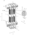
- FIG. 1 is a perspective view showing a schematic configuration of a probe for a probe card according to a first embodiment
- FIG. 3 is a diagram showing the relationship between the overdrive amount of the probe and the stylus pressure according to the first embodiment.
- FIG. 3 is a diagram showing the relationship between the overdrive amount of the probe and the stress acting on the probe according to the first embodiment.
- 11 is a cross-sectional view showing a framework region having many recesses according to the first embodiment;
- FIG. FIG. 3 is a diagram showing a manufacturing process of a probe by electroforming according to the first embodiment.
- 5A to 5C are diagrams showing a manufacturing process of a probe by electroforming according to the first embodiment.
- FIG. 3 is a diagram showing a method for manufacturing a probe by pressing according to the first embodiment.
- FIG. 7 is an enlarged view of the main part of the probe according to Embodiment 2 in a plane perpendicular to the buckling direction X;
- FIG. 7 is a diagram showing a surface on which a deformable region of a probe according to Embodiment 2 is provided.
- 7 is an enlarged view of a main part of a probe according to Embodiment 3 in a plane perpendicular to the buckling direction X.
- FIG. FIG. 7 is an enlarged view of a main part of a probe according to Embodiment 4 in a plane perpendicular to the buckling direction X;
- 13 is an enlarged view of a main portion of a surface perpendicular to a buckling direction X of a probe according to embodiment 5.
- FIG. 7 is a diagram showing a modification of the fifth embodiment.
- FIG. 7 is an enlarged view of the main part of the probe according to Embodiment 6 in a plane perpendicular to the buckling direction X; 13 is an enlarged view of a main portion of a surface perpendicular to a buckling direction X of a probe according to a seventh embodiment.
- FIG. FIG. 7 is an enlarged view of the main part of a probe according to Embodiment 8 in a plane perpendicular to the buckling direction X;
- FIG. 15A is a sectional view taken along line BB in FIG. 15A.
- FIG. 9 is a diagram showing a partial cross-sectional shape of a probe according to a ninth embodiment.
- FIG. 1 is a perspective view showing the structure of a probe 1 for a probe card.
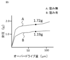
- FIG. 2 is a diagram showing the relationship between the overdrive amount of the probe 1 and the needle pressure.
- FIG. 3 is a diagram showing the relationship between the overdrive amount of the probe and the stress acting on the probe.
- FIG. 4 is a partial cross-sectional view of the deformation region 8 and the framework region 9.
- the probe 1 is a so-called vertical probe, and is held substantially vertically by a first guide plate 2 on the upper side and a second guide plate 3 on the lower side.
- the tip portion 4 of the probe 1 is guided by the second guide plate 3 so as to contact the electrode pad 5 of the semiconductor device.
- a rear end portion 6 of the probe 1 (top side of the paper in FIG. 1) is guided by a first guide plate 2 so as to be connected to an electrode (not shown) connected to a circuit board of a probe card.
- the probe 1 is made of a thin metal plate of a conductive member, and at least one surface 1S (front or back surface) perpendicular to the buckling direction X of the central portion 7 of the probe 1 has a plurality of deformation regions 8 and a skeleton region. 9 is formed.
- the buckling direction X is the direction in which the probe 1 curves during so-called overdrive of the probe card.
- the deformed region 8 refers to a region where the reference surface 1SB, which is the original plane of the probe card, is deformed and a depression is formed.
- the framework region 9 indicates a region that connects a plurality of deformation regions 8. Further, the boundary between the deformation region 8 and the framework region 9 is represented as a ridgeline 10.
- FIG. 1 shows an example in which a rectangular prism-shaped depression is provided as the deformation region 8 on the reference surface 1SB, which is the original plane. Therefore, when the deformation region 8 is viewed in the buckling direction X of the probe 1, its outer edge is square. Further, the frame region 9 corresponds to the plane portion between the deformation regions 8.
- a plurality of deformable regions 8 are arranged in a predetermined direction D1 in a predetermined direction D1 with respect to the longitudinal direction Z of the probe 1 at intervals P, and a plurality of deformable regions 8 are arranged in a plurality of rows in the longitudinal direction of the probe 1. .
- the spacing P is the width of the framework region 9.
- the direction D1 is perpendicular to the longitudinal direction Z of the probe 1.
- the following results were obtained. That is, the measurement results of the probe without the deformation region 8 on the surface are represented as A, and the measurement results of the characteristics of the probe 1 with the deformation region 8 provided are represented as B, and the tip portion 4 of the probe 1 contacts the electrode pad 5.
- the relationship between the needle pressure and the overdrive amount is as shown in FIG. 2. Further, the relationship between stress and overdrive amount is as shown in FIG. 3.
- the stylus force when the overdrive amount is 70 ⁇ m was 1.72 gf for the probe without the recessed deformation region 8, whereas the probe with the recessed deformation region 8 1, it was 1.19gf.
- the maximum stress when the overdrive amount was 110 ⁇ m was 670 MPa for the probe without a depression, whereas it was 891 MPa for the probe 1 provided with the depression-shaped deformation region 8. It was confirmed that the mechanical properties as a probe could be satisfied.
- the surface area of the probe 1 is increased by providing the deformation region 8 in the shape of a rectangular prism depression on the surface of the probe 1.
- the surface area of the top of the rectangular prism simply pushes down the original surface, so there is no change in area. do not have.
- the area of the inner wall surface caused by the depression has increased.
- the dimensions of the recesses provided on the front and back sides of the probe are rectangular with each side of 20 ⁇ m, the depth of the recess on the front side is 3.5 ⁇ m, and the depth of the recess on the back side is 2.5 ⁇ m.
- the area on the front side increases by 120,120 ⁇ m 2
- the area on the back side increases by 85,800 ⁇ m 2 .
- the surface area increases by the area of the inner wall surface of the depression caused by the depression.
- Probe A has no depressions (smooth surface)
- Probe B has square prism-shaped depressions arranged in a matrix
- Probe C has square prism-shaped depressions arranged in a staggered manner
- Probe D has circular depressions arranged in a staggered manner.
- the probe stylus pressure and maximum stress were determined based on the finite element method (FEM), and the results are as shown in Table 1.
- probe A As shown in Table 1, in the case of probe A, the stylus force was 1.72 gf when the overdrive was 70 ⁇ m, and the maximum stress was 670 MPa when the overdrive was 110 ⁇ m.
- probe B has a needle pressure of 1.19 gf and maximum stress of 891 Mpa
- probe C has a needle pressure of 1.18 gf and maximum stress of 899 Mpa
- probe D has needle pressure of 1.18 gf and maximum stress of 899 Mpa.
- the pressure was 1.18gf and the maximum stress was 1164Mpa.
- probe A had a maximum stress of 670 MPa and was almost uniformly distributed.
- the situation was as follows.
- the stress was 74 MPa in the flat part of the bottom of the deformation region 8 and 668 MPa in the framework region 9, and the maximum stress was 891 MPa.
- probe C the stress was 74 MPa at the bottom flat part of the deformation area 8 and 674 MPa at the frame area 9, and the maximum stress was 899 MPa.
- probe D the stress was 97 MPa in the spherical part of the bottom of the deformation region 8 and 873 MPa in the frame region 9, and the maximum stress was 1164 MPa.
- the deformation region 8 is formed by a cone-shaped or pyramid-shaped depression, stress can be dispersed not only at each apex of the outer circumference but also at the apex of the cone or pyramid. In this case, stress concentration occurring on the ridge line 10 at the boundary between the deformation region 8 and the frame region 9 can be reduced.
- edge line 10 is polygonal, stress concentration occurs at each vertex, but the greater the number of angles, the smaller the stress concentration borne by each vertex individually. From this, if the periphery of the depression is circular, the stress will be dispersed around the periphery, so as explained for probe D, a structure in which a spherical depression shape is provided as the deformation area 8 will disperse the stress the most. It is estimated that the probe has a structure with high mechanical strength.
- the first manufacturing method is an electroforming manufacturing method.
- 5A and 5B are diagrams showing the manufacturing process of the probe 1 by electroforming.
- the deformation region 8 is formed by forming a protruding shape corresponding to the concave shape of the conductive layer 42 on the surface of the substrate 41, and then providing the metal layer 43, which will become a member of the probe 1, on the surface of the conductive layer 42. It is.
- This metal layer 43 can be formed, for example, by electroforming.
- the surface is processed to be flat, a mask is provided, and etching is performed to create the target probe.
- the probe 1 is removed from the substrate 41 by removing the conductive layer 42.
- the second manufacturing method is a manufacturing method using a press.
- FIG. 6 is a diagram showing a method of manufacturing the probe 1 by pressing.
- the metal plate 53 is pressed from both sides by a first mold 51 and a second mold 52, each having a surface corresponding to the shape of a recess, to form a deformed region 8 in the shape of a recess on the surface.
- FIG. 7 is an enlarged view of the main part of the surface 1S perpendicular to the buckling direction X of the probe 1, and is a diagram showing another example of the arrangement of the deformation region 8.
- FIG. 8 is a diagram showing a surface of the probe 1 on which the deformation region 8 is provided. Similar to the first embodiment, the deformation region 8 is provided on at least one surface 1S of the probe 1 perpendicular to the buckling direction X.
- the deformation regions 8 are arranged in a predetermined direction D2 with respect to the longitudinal direction Z of the probe 1, with a plurality of deformation regions 8 arranged in a row in the longitudinal direction Z of the probe 1, each with an interval P between them.
- the direction D2 is an oblique direction with respect to the longitudinal direction Z of the probe 1.
- each deformation region 8 When viewed in the buckling direction X, each deformation region 8 has a rectangular ridge 10 (outer edge). Therefore, the actual shape is a depression or protrusion in the shape of a rectangular prism, a rectangular pyramid, a truncated rectangular pyramid, or the like.
- the two opposing sides of the rectangular ridge 10 of the deformation region 8 are parallel to the predetermined direction D2, and the other two sides are perpendicular to the direction D2.
- the distance between adjacent deformation regions 8 aligned in a direction perpendicular to the direction D2 is also the same as the distance P.
- the deformation regions 8 are also aligned straight and at equal intervals in the longitudinal direction Z of the probe 1.
- the shapes of the deformation regions 8 of the truncated circular cone, elliptical cone, and polygonal pyramid gradually increase in cross-sectional area toward the reference plane 1SB.
- the probe for a probe card according to the second embodiment by regularly arranging the deformation regions 8 having the same shape, regular distribution of stress is achieved, and the probe has high mechanical strength.
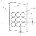
- FIG. 9 is an enlarged view of a main portion of a surface 1S perpendicular to the buckling direction X of the probe 1, showing another example of the arrangement of the deformation region 8.
- FIG. 9 is an enlarged view of a main portion of a surface 1S perpendicular to the buckling direction X of the probe 1, showing another example of the arrangement of the deformation region 8.
- a plurality of deformable regions 8 are arranged in a predetermined direction D1 in a predetermined direction D1 with respect to the longitudinal direction Z of the probe 1, and a plurality of deformable regions 8 are arranged in one row in the longitudinal direction Z of the probe 1 with an interval P between them.
- the direction D1 is perpendicular to the longitudinal direction Z of the probe 1.
- each deformation region 8 When each deformation region 8 is viewed in the buckling direction X, its ridgeline 10 (outer edge) is circular (a type of ellipse). Therefore, the actual shape is a depression or protrusion in the shape of a cylinder, cone, truncated cone, spherical surface, or the like.
- the distance between adjacent deformation regions 8 in the longitudinal direction Z of the probe 1 is also the same as the distance P described above.
- the probe for a probe card according to the third embodiment as in the first and second embodiments, by regularly arranging deformation regions 8 having the same shape, regular distribution of stress is achieved, and mechanical strength is improved. We can provide probes for probe cards with high performance.
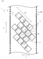
- FIG. 10 is an enlarged view of the main part of the surface 1S perpendicular to the buckling direction X of the probe 1, and is a diagram showing another example of the arrangement of the deformation region 8. Similar to the second embodiment, the deformation region 8 is provided on at least one of the surfaces 1S perpendicular to the buckling direction X.
- the deformation regions 8 are arranged in a predetermined direction D2 with respect to the longitudinal direction Z of the probe 1, with a plurality of deformation regions 8 arranged in a row in the longitudinal direction Z of the probe 1, each with an interval P between them.
- the direction D2 is an oblique direction with respect to the longitudinal direction Z of the probe 1.
- Each deformation region 8 has a rectangular ridgeline 10 (outer edge) when viewed in the buckling direction X. Therefore, the actual shape is a depression or a protrusion in the shape of a quadrangular prism, a quadrangular pyramid, a truncated quadrangular pyramid, or the like.
- Two opposing sides of the quadrangular ridgeline 10 (outer edge) of the deformation region 8 are arranged parallel to a predetermined direction D2, and the other two sides are perpendicular to the direction D2.
- the distance between the deformation regions 8 adjacent to each other in the direction perpendicular to the direction D2 is also the same as the distance P.
- Embodiment 2 The difference from Embodiment 2 is that in Embodiment 2, the deformation regions 8 are arranged straight in the longitudinal direction Z of the probe 1 at equal intervals, but in Embodiment 4, the deformation regions 8 are , are not lined up straight in the longitudinal direction Z of the probe 1.
- the first row L1, the second row L2, the third row L3, and the fourth row L4 each consist of four (actually more) deformation regions, but the first row L1
- the deformation regions 8 of the second row L2 and the deformation regions 8 of the second row L2 are arranged alternately along the direction D2.
- the centers S of all the deformable regions 8 in the first row L1 are not aligned with the centers S of any deformable regions 8 in the second row L2 in the longitudinal direction Z of the probe 1.
- a side of the deformation area 8 in the Nth column that constitutes the ridge 10 of the second deformation area 8 from the top of the Nth column and that faces the ridge 10 of the deformation area 8 in the N+1th column will face parallel to each of the sides that constitute the ridges 10 of the two deformation areas 8 in the N+1th column.
- the corners K of the two deformation areas 8 are close to each other. Note that the spacing between adjacent deformation areas 8 is the same, as in embodiment 2.
- the corners K of the deformation region 8 where stress is concentrated are adjacent to each other. Compared to the four corners K adjacent to each other in the second embodiment, the number of places where stress is concentrated can be increased by approximately twice. This further distributes stress and provides a probe for a probe card with high mechanical strength.
- FIG. 11 is an enlarged view of the main part of the surface 1S perpendicular to the buckling direction X of the probe 1, and is a diagram showing another example of the arrangement of the deformation region 8. Similar to the third embodiment, the deformation region 8 is provided on at least one of the surfaces 1S perpendicular to the buckling direction X.
- a plurality of deformable regions 8 are arranged in a predetermined direction D1 in a predetermined direction D1 with respect to the longitudinal direction Z of the probe 1, and a plurality of deformable regions 8 are arranged in one row in the longitudinal direction Z of the probe 1 with an interval P between them.
- the direction D1 is perpendicular to the longitudinal direction Z of the probe 1.
- Each deformation region 8 has a circular ridgeline 10 (outer edge) when viewed in the buckling direction X. Therefore, the actual shape is a depression or protrusion in the shape of a cylinder, cone, truncated cone, or the like.
- the intervals between adjacent deformation regions 8 are all the same as the interval P described above.
- the difference from Embodiment 3 is that in Embodiment 3, the centers of the deformation regions 8 are lined up straight in the longitudinal direction Z of the probe 1 at equal intervals, but in Embodiment 4, the centers of the deformation regions 8 8 are not lined up straight in the longitudinal direction Z of the probe 1.
- the first row L1 consists of two deformation regions (actually more), and the second row L2 consists of three deformation regions 8.
- the third row L3 consists of two deformation regions 8. In this way, the number of deformation regions 8 configuring adjacent columns is different.
- the deformation regions 8 in the first row L1 and the deformation regions 8 in the second row L2 are arranged alternately along the direction D1. The same applies to each deformation area in the second row L2 and the third row L3. Note that the intervals between adjacent deformation regions 8 are all the same as in the third embodiment, but as can be seen by comparing FIG. 9 and FIG.
- the deformation regions 8 can be arranged at a high density relative to the area.
- FIG. 12 is a diagram showing a modification of the fifth embodiment.
- the deformation region 8 may have an elliptical ridgeline 10 (outer edge) when viewed in the buckling direction X.
- the deformation regions 8 can be arranged with high density, stress can be further dispersed and a probe for a probe card with high mechanical strength can be provided.
- FIG. 13 is an enlarged view of a main portion of a surface 1S perpendicular to the buckling direction X of the probe 1, showing another example of the arrangement of the deformation region 8.
- FIG. 13 is an enlarged view of a main portion of a surface 1S perpendicular to the buckling direction X of the probe 1, showing another example of the arrangement of the deformation region 8.
- the deformation regions 8 are arranged in a row with a plurality of deformation regions 8 spaced apart from each other by an interval P in a predetermined direction D2 with respect to the longitudinal direction Z of the probe 1.
- the direction D2 is oblique to the longitudinal direction Z of the probe 1.
- the deformation regions 8 in each row have rectangular ridges 10.
- the centers S of the deformation regions 8 in each row are also aligned in the longitudinal direction Z of the probe 1, but there are only a maximum of two adjacent corners K. This example provides the same effects as the fourth embodiment.
- FIG. 14 is an enlarged view of a main part of a surface 1S perpendicular to the buckling direction X of the probe 1 provided with a depression in the shape of a truncated triangular pyramid.
- a plurality of deformable regions 8 are arranged in a predetermined direction D1 in a predetermined direction D1 with respect to the longitudinal direction Z of the probe 1, and a plurality of deformable regions 8 are arranged in one row in the longitudinal direction Z of the probe 1 with an interval P between them.
- the direction D1 is perpendicular to the longitudinal direction Z of the probe 1.
- the deformation regions 8 forming the first row L1 and the deformation regions 8 forming the second row L2 are reversed in the vertical direction of the plane of FIG. 14. Further, the deformation region 8 is recessed from the reference surface 1SB in the shape of a truncated triangular pyramid.
- the deformation regions 8 can be arranged with high density, stress can be further dispersed and a probe for a probe card with high mechanical strength can be provided. Further, the strength of the frame region 9 can be strengthened.
- FIG. 15A is an enlarged view of a main part of a probe provided with a truncated conical protrusion in addition to a truncated conical depression.
- FIG. 15B is a cross-sectional view taken along line BB in FIG. 15A.
- the reference surface 1SB of the probe 1 has a first deformation area 91 that is a truncated cone-shaped depression with a first diameter of a large diameter and a truncated cone with a second diameter of a small diameter. It has a structure in which a second deformation region 92 having a protruding shape is provided on the reference surface 1SB.
- first deformation regions 91 are arranged in a staggered manner, and second deformation regions 92 are arranged in the spaces between the first deformation regions 91. Due to the arrangement of the first deformation region 91 and the second deformation region 92, stress is uniformly distributed, resulting in a probe having a structure with high mechanical strength. In this way, the deformed region may have a shape that protrudes from the reference surface 1SB, or may have a concave shape.
- FIG. 16 shows a partial cross-sectional shape of the probe 1 according to the tenth embodiment.
- a coating layer 13 is provided to prevent foreign matter from adhering to the surface of the metal plate of the probe 1 shown in embodiments 1 to 8. Furthermore, the surface of the metal plate is covered smoothly so that even if foreign matter adheres, it can be easily removed. With this configuration, if the probe has a deformed region in the shape of a depression or a protrusion on the surface of the metal plate, the problem of foreign matter adhesion can be solved by similarly providing a coating layer.
- the material for the covering layer 13 is preferably a resin layer that does not hinder the deformation of the metal plate.
- the surface is provided with a plurality of deformed regions 8 having a concave shape or a protruding shape, so there is a concern that foreign matter may adhere to the surface.In order to eliminate this concern, the surface is made smooth.
- the coating layer 13 for this purpose is effective.
- a probe 1 with high mechanical strength and free from adhesion of foreign matter is obtained. be able to. Note that it may be covered with a material other than resin and made of a material different from that of the structure of the probe 1.
Landscapes
- Physics & Mathematics (AREA)
- General Physics & Mathematics (AREA)
- Geometry (AREA)
- Measuring Leads Or Probes (AREA)
- Testing Or Measuring Of Semiconductors Or The Like (AREA)
- Testing Of Individual Semiconductor Devices (AREA)
Priority Applications (6)
| Application Number | Priority Date | Filing Date | Title |
|---|---|---|---|
| US19/113,865 US20260098876A1 (en) | 2022-09-21 | 2022-09-21 | Probe for probe card |
| JP2024547995A JP7847658B2 (ja) | 2022-09-21 | 2022-09-21 | プローブカード用プローブ |
| KR1020257008799A KR20250048474A (ko) | 2022-09-21 | 2022-09-21 | 프로브 카드용 프로브 |
| CN202280100291.4A CN119923568A (zh) | 2022-09-21 | 2022-09-21 | 探针卡用探针 |
| PCT/JP2022/035187 WO2024062558A1 (ja) | 2022-09-21 | 2022-09-21 | プローブカード用プローブ |
| TW112134918A TW202429089A (zh) | 2022-09-21 | 2023-09-13 | 用於探針卡之探針 |
Applications Claiming Priority (1)
| Application Number | Priority Date | Filing Date | Title |
|---|---|---|---|
| PCT/JP2022/035187 WO2024062558A1 (ja) | 2022-09-21 | 2022-09-21 | プローブカード用プローブ |
Publications (1)
| Publication Number | Publication Date |
|---|---|
| WO2024062558A1 true WO2024062558A1 (ja) | 2024-03-28 |
Family
ID=90454058
Family Applications (1)
| Application Number | Title | Priority Date | Filing Date |
|---|---|---|---|
| PCT/JP2022/035187 Ceased WO2024062558A1 (ja) | 2022-09-21 | 2022-09-21 | プローブカード用プローブ |
Country Status (6)
| Country | Link |
|---|---|
| US (1) | US20260098876A1 (https=) |
| JP (1) | JP7847658B2 (https=) |
| KR (1) | KR20250048474A (https=) |
| CN (1) | CN119923568A (https=) |
| TW (1) | TW202429089A (https=) |
| WO (1) | WO2024062558A1 (https=) |
Cited By (2)
| Publication number | Priority date | Publication date | Assignee | Title |
|---|---|---|---|---|
| JPWO2024062561A1 (https=) * | 2022-09-21 | 2024-03-28 | ||
| JPWO2024062560A1 (https=) * | 2022-09-21 | 2024-03-28 |
Citations (5)
| Publication number | Priority date | Publication date | Assignee | Title |
|---|---|---|---|---|
| JP2007078371A (ja) * | 2005-09-09 | 2007-03-29 | Nhk Spring Co Ltd | 導電性接触子および導電性接触子の製造方法 |
| JP2008503734A (ja) * | 2004-06-21 | 2008-02-07 | カプレス・アクティーゼルスカブ | プローブの位置合せを行なう方法 |
| US20090315578A1 (en) * | 2008-06-18 | 2009-12-24 | Star Technologies Inc. | Probe and probe card for integrated circuit devices using the same |
| JP2018515752A (ja) * | 2015-03-31 | 2018-06-14 | テクノプローベ エス.ピー.エー. | 高周波適用のためのバーチカル接触プローブ、及びバーチカル接触プローブをもつ試験ヘッド |
| US20190064215A1 (en) * | 2017-08-23 | 2019-02-28 | Leeno Industrial Inc. | Mems probe and test device using the same |
-
2022
- 2022-09-21 JP JP2024547995A patent/JP7847658B2/ja active Active
- 2022-09-21 WO PCT/JP2022/035187 patent/WO2024062558A1/ja not_active Ceased
- 2022-09-21 KR KR1020257008799A patent/KR20250048474A/ko active Pending
- 2022-09-21 US US19/113,865 patent/US20260098876A1/en active Pending
- 2022-09-21 CN CN202280100291.4A patent/CN119923568A/zh active Pending
-
2023
- 2023-09-13 TW TW112134918A patent/TW202429089A/zh unknown
Patent Citations (5)
| Publication number | Priority date | Publication date | Assignee | Title |
|---|---|---|---|---|
| JP2008503734A (ja) * | 2004-06-21 | 2008-02-07 | カプレス・アクティーゼルスカブ | プローブの位置合せを行なう方法 |
| JP2007078371A (ja) * | 2005-09-09 | 2007-03-29 | Nhk Spring Co Ltd | 導電性接触子および導電性接触子の製造方法 |
| US20090315578A1 (en) * | 2008-06-18 | 2009-12-24 | Star Technologies Inc. | Probe and probe card for integrated circuit devices using the same |
| JP2018515752A (ja) * | 2015-03-31 | 2018-06-14 | テクノプローベ エス.ピー.エー. | 高周波適用のためのバーチカル接触プローブ、及びバーチカル接触プローブをもつ試験ヘッド |
| US20190064215A1 (en) * | 2017-08-23 | 2019-02-28 | Leeno Industrial Inc. | Mems probe and test device using the same |
Cited By (3)
| Publication number | Priority date | Publication date | Assignee | Title |
|---|---|---|---|---|
| JPWO2024062561A1 (https=) * | 2022-09-21 | 2024-03-28 | ||
| JPWO2024062560A1 (https=) * | 2022-09-21 | 2024-03-28 | ||
| JP7853431B2 (ja) | 2022-09-21 | 2026-04-28 | 日本電子材料株式会社 | プローブカード用プローブ |
Also Published As
| Publication number | Publication date |
|---|---|
| JP7847658B2 (ja) | 2026-04-17 |
| JPWO2024062558A1 (https=) | 2024-03-28 |
| TW202429089A (zh) | 2024-07-16 |
| KR20250048474A (ko) | 2025-04-08 |
| US20260098876A1 (en) | 2026-04-09 |
| CN119923568A (zh) | 2025-05-02 |
Similar Documents
| Publication | Publication Date | Title |
|---|---|---|
| WO2024062558A1 (ja) | プローブカード用プローブ | |
| JP7470860B2 (ja) | プローブカード用プローブおよびその製造方法 | |
| JP2500830Y2 (ja) | 集積回路検査装置 | |
| CN112164318A (zh) | 支撑件及可折叠显示模组 | |
| US6217343B1 (en) | Multipoint conductive sheet | |
| TWI766154B (zh) | 探針頭及探針卡 | |
| US20080134502A1 (en) | Connector having staggered contact architecture for enhanced working range | |
| JP2004156993A (ja) | プローブ及びこれを用いた電気的接続装置 | |
| TW484172B (en) | Metal bump | |
| KR101148542B1 (ko) | 플립 칩 구성을 갖는 전기 소자 | |
| JP2023091901A (ja) | 半導体製造装置および半導体装置の製造方法 | |
| JP5096825B2 (ja) | プローブ及び電気的接続装置 | |
| TWI825804B (zh) | 電子裝置、其電路板及電子裝置之製造方法 | |
| JPWO2024062558A5 (https=) | ||
| US12601759B2 (en) | Cantilever probe card device and light scattering probe | |
| US20130154902A1 (en) | Artificial electromagnetic material | |
| KR102836396B1 (ko) | 검사용 커넥터 | |
| JP7853431B2 (ja) | プローブカード用プローブ | |
| CN111458785A (zh) | 一种具有亮度提升的导光板及其加工方法 | |
| JPH06246857A (ja) | 可撓性フィルム基板 | |
| CN100565860C (zh) | 基板上的凸块结构 | |
| US12332278B2 (en) | Probe card | |
| WO2024057613A1 (ja) | 電気的接続装置 | |
| TW202418665A (zh) | 板對板連接器 | |
| TWI491964B (zh) | 顯示裝置 |
Legal Events
| Date | Code | Title | Description |
|---|---|---|---|
| 121 | Ep: the epo has been informed by wipo that ep was designated in this application |
Ref document number: 22959522 Country of ref document: EP Kind code of ref document: A1 |
|
| WWE | Wipo information: entry into national phase |
Ref document number: 2024547995 Country of ref document: JP |
|
| ENP | Entry into the national phase |
Ref document number: 20257008799 Country of ref document: KR Kind code of ref document: A |
|
| WWE | Wipo information: entry into national phase |
Ref document number: 1020257008799 Country of ref document: KR |
|
| WWE | Wipo information: entry into national phase |
Ref document number: 202280100291.4 Country of ref document: CN |
|
| WWP | Wipo information: published in national office |
Ref document number: 1020257008799 Country of ref document: KR |
|
| NENP | Non-entry into the national phase |
Ref country code: DE |
|
| WWE | Wipo information: entry into national phase |
Ref document number: 11202501717Y Country of ref document: SG |
|
| WWP | Wipo information: published in national office |
Ref document number: 11202501717Y Country of ref document: SG |
|
| WWP | Wipo information: published in national office |
Ref document number: 202280100291.4 Country of ref document: CN |
|
| 122 | Ep: pct application non-entry in european phase |
Ref document number: 22959522 Country of ref document: EP Kind code of ref document: A1 |