WO2024053415A1 - ナット及びボールねじ装置 - Google Patents
ナット及びボールねじ装置 Download PDFInfo
- Publication number
- WO2024053415A1 WO2024053415A1 PCT/JP2023/030514 JP2023030514W WO2024053415A1 WO 2024053415 A1 WO2024053415 A1 WO 2024053415A1 JP 2023030514 W JP2023030514 W JP 2023030514W WO 2024053415 A1 WO2024053415 A1 WO 2024053415A1
- Authority
- WO
- WIPO (PCT)
- Prior art keywords
- nut
- flange
- partial
- shaped groove
- screw shaft
- Prior art date
- Legal status (The legal status is an assumption and is not a legal conclusion. Google has not performed a legal analysis and makes no representation as to the accuracy of the status listed.)
- Ceased
Links
Images







Classifications
-
- F—MECHANICAL ENGINEERING; LIGHTING; HEATING; WEAPONS; BLASTING
- F16—ENGINEERING ELEMENTS AND UNITS; GENERAL MEASURES FOR PRODUCING AND MAINTAINING EFFECTIVE FUNCTIONING OF MACHINES OR INSTALLATIONS; THERMAL INSULATION IN GENERAL
- F16H—GEARING
- F16H25/00—Gearings comprising primarily only cams, cam-followers and screw-and-nut mechanisms
- F16H25/18—Gearings comprising primarily only cams, cam-followers and screw-and-nut mechanisms for conveying or interconverting oscillating or reciprocating motions
- F16H25/20—Screw mechanisms
- F16H25/22—Screw mechanisms with balls, rollers, or similar members between the co-operating parts; Elements essential to the use of such members
- F16H25/2204—Screw mechanisms with balls, rollers, or similar members between the co-operating parts; Elements essential to the use of such members with balls
-
- F—MECHANICAL ENGINEERING; LIGHTING; HEATING; WEAPONS; BLASTING
- F16—ENGINEERING ELEMENTS AND UNITS; GENERAL MEASURES FOR PRODUCING AND MAINTAINING EFFECTIVE FUNCTIONING OF MACHINES OR INSTALLATIONS; THERMAL INSULATION IN GENERAL
- F16H—GEARING
- F16H25/00—Gearings comprising primarily only cams, cam-followers and screw-and-nut mechanisms
- F16H25/18—Gearings comprising primarily only cams, cam-followers and screw-and-nut mechanisms for conveying or interconverting oscillating or reciprocating motions
- F16H25/20—Screw mechanisms
- F16H25/22—Screw mechanisms with balls, rollers, or similar members between the co-operating parts; Elements essential to the use of such members
- F16H25/2204—Screw mechanisms with balls, rollers, or similar members between the co-operating parts; Elements essential to the use of such members with balls
- F16H25/2214—Screw mechanisms with balls, rollers, or similar members between the co-operating parts; Elements essential to the use of such members with balls with elements for guiding the circulating balls
- F16H25/2223—Cross over deflectors between adjacent thread turns, e.g. S-form deflectors connecting neighbouring threads
-
- F—MECHANICAL ENGINEERING; LIGHTING; HEATING; WEAPONS; BLASTING
- F16—ENGINEERING ELEMENTS AND UNITS; GENERAL MEASURES FOR PRODUCING AND MAINTAINING EFFECTIVE FUNCTIONING OF MACHINES OR INSTALLATIONS; THERMAL INSULATION IN GENERAL
- F16H—GEARING
- F16H25/00—Gearings comprising primarily only cams, cam-followers and screw-and-nut mechanisms
- F16H25/18—Gearings comprising primarily only cams, cam-followers and screw-and-nut mechanisms for conveying or interconverting oscillating or reciprocating motions
- F16H25/20—Screw mechanisms
- F16H25/2015—Means specially adapted for stopping actuators in the end position; Position sensing means
-
- F—MECHANICAL ENGINEERING; LIGHTING; HEATING; WEAPONS; BLASTING
- F16—ENGINEERING ELEMENTS AND UNITS; GENERAL MEASURES FOR PRODUCING AND MAINTAINING EFFECTIVE FUNCTIONING OF MACHINES OR INSTALLATIONS; THERMAL INSULATION IN GENERAL
- F16H—GEARING
- F16H25/00—Gearings comprising primarily only cams, cam-followers and screw-and-nut mechanisms
- F16H25/18—Gearings comprising primarily only cams, cam-followers and screw-and-nut mechanisms for conveying or interconverting oscillating or reciprocating motions
- F16H25/20—Screw mechanisms
- F16H25/24—Elements essential to such mechanisms, e.g. screws, nuts
-
- F—MECHANICAL ENGINEERING; LIGHTING; HEATING; WEAPONS; BLASTING
- F16—ENGINEERING ELEMENTS AND UNITS; GENERAL MEASURES FOR PRODUCING AND MAINTAINING EFFECTIVE FUNCTIONING OF MACHINES OR INSTALLATIONS; THERMAL INSULATION IN GENERAL
- F16H—GEARING
- F16H25/00—Gearings comprising primarily only cams, cam-followers and screw-and-nut mechanisms
- F16H25/18—Gearings comprising primarily only cams, cam-followers and screw-and-nut mechanisms for conveying or interconverting oscillating or reciprocating motions
- F16H25/20—Screw mechanisms
- F16H2025/204—Axial sliding means, i.e. for rotary support and axial guiding of nut or screw shaft
-
- F—MECHANICAL ENGINEERING; LIGHTING; HEATING; WEAPONS; BLASTING
- F16—ENGINEERING ELEMENTS AND UNITS; GENERAL MEASURES FOR PRODUCING AND MAINTAINING EFFECTIVE FUNCTIONING OF MACHINES OR INSTALLATIONS; THERMAL INSULATION IN GENERAL
- F16H—GEARING
- F16H25/00—Gearings comprising primarily only cams, cam-followers and screw-and-nut mechanisms
- F16H25/18—Gearings comprising primarily only cams, cam-followers and screw-and-nut mechanisms for conveying or interconverting oscillating or reciprocating motions
- F16H25/20—Screw mechanisms
- F16H2025/2062—Arrangements for driving the actuator
- F16H2025/2075—Coaxial drive motors
-
- F—MECHANICAL ENGINEERING; LIGHTING; HEATING; WEAPONS; BLASTING
- F16—ENGINEERING ELEMENTS AND UNITS; GENERAL MEASURES FOR PRODUCING AND MAINTAINING EFFECTIVE FUNCTIONING OF MACHINES OR INSTALLATIONS; THERMAL INSULATION IN GENERAL
- F16H—GEARING
- F16H25/00—Gearings comprising primarily only cams, cam-followers and screw-and-nut mechanisms
- F16H25/18—Gearings comprising primarily only cams, cam-followers and screw-and-nut mechanisms for conveying or interconverting oscillating or reciprocating motions
- F16H25/20—Screw mechanisms
- F16H2025/2062—Arrangements for driving the actuator
- F16H2025/2087—Arrangements for driving the actuator using planetary gears
Definitions
- the present disclosure relates to a nut and a ball screw device.
- the ball screw device includes a screw shaft, a nut passed through the screw shaft, and a plurality of balls arranged between the screw shaft and the nut.
- An outer circumferential raceway surface is provided on the outer circumferential surface of the screw shaft.
- the inner circumferential surface of the nut is provided with an inner circumferential raceway surface that faces the outer circumferential raceway surface.
- a spiral orbit is formed between the outer circumferential raceway surface and the inner circumferential raceway surface.
- a plurality of balls are placed on this trajectory.
- the ball screw device also includes a circulation section that circulates the balls.
- An example of the circulation part is an S-shaped groove formed on the inner peripheral surface of the nut. According to this S-shaped groove surface, a ball that has moved one lead can be returned by one lead.
- the nut may have a flange that projects outward in the radial direction.
- the present disclosure has been made in view of the above, and aims to provide a nut that can avoid increasing the size in the axial direction, and a ball screw device equipped with the nut.
- a nut includes a cylindrical nut body that is penetrated by a screw shaft, and a plurality of inner circumferential orbits that are recessed radially outward from an inner circumferential surface of the nut body.
- the nut includes a surface, a plurality of S-shaped groove surfaces, and a flange protruding radially outward from the outer peripheral surface of the nut main body.
- the flange is composed of at least one partial flange extending only in a part of the circumferential direction along the outer peripheral surface of the nut main body.
- the space When there is one partial flange, the space is between one end and the other end of the partial flange in the circumferential direction; when there are two or more partial flanges, the space is between the circumferentially adjacent partial flanges.
- One of the plurality of S-shaped groove surfaces is arranged radially inward with respect to the escape space.
- the meat part of the nut body can be released into the escape space. That is, the S-shaped groove surface can be formed by forging in a portion of the nut body that is disposed radially inward with respect to the relief space. As a result, there is no need to form the S-shaped groove surface with a shift in the axial direction with respect to the flange (partial flange), and an increase in the size of the nut in the axial direction is avoided. Further, according to the present disclosure, the nut is lighter than when the flange is annular.
- the plurality of S-shaped groove surfaces are arranged at equal intervals in the circumferential direction.
- the nut supports the screw shaft from the outside in the radial direction via the ball. Further, the inner circumferential raceway surface extends in the circumferential direction, and the range of support from the outside in the radial direction extends in the circumferential direction. On the other hand, the portion in the circumferential direction where the S-shaped groove surface is provided cannot support the screw shaft from the outside in the radial direction. According to the configuration, the range in which the screw shaft cannot be supported from the outside in the radial direction is dispersed in the circumferential direction. Therefore, the screw shaft can be supported from all circumferential directions.
- the flange may have two or more partial flanges arranged at equal intervals in the circumferential direction.
- a shaft is disposed on the radially outer side of the partial flange, and is supported by the housing and extends in an axial direction parallel to the screw shaft.
- the outer peripheral surface of the partial flange is provided with a sliding groove surface that is recessed radially inward and in which the shaft is accommodated.
- the nut is supported by the housing so as to be non-rotatable and movable in the axial direction.
- the planetary gear of the planetary gear mechanism and the partial flange face each other in an axial direction parallel to the screw shaft.
- the partial flange is provided with a hole into which a transmission shaft that supports the planetary gear is inserted.
- the nut body is disposed inside the driven pulley.
- the partial flange is inserted into a groove provided on the inner peripheral surface of the driven pulley.
- one end surface of the nut body is provided with a protrusion that protrudes in the axial direction and comes into contact with a stopper that does not rotate relative to the screw shaft.
- the S-shaped groove surface that is disposed closest to the protrusion in the axial direction is disposed offset in the circumferential direction with respect to the protrusion.
- the ball screw device of the present disclosure includes a screw shaft, the aforementioned nut, and a plurality of balls arranged between the screw shaft and the nut.
- the nut is lighter than when the flange is annular.
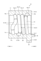
- FIG. 1 is a cross-sectional view taken in the axial direction of the brake booster according to the first embodiment before operation.
- FIG. 2 is an enlarged view of a part of the nut shown in FIG. 1.
- FIG. 3 is a diagram of the nut of Embodiment 1 viewed from the second direction.
- FIG. 4 is a perspective view of the nut of Embodiment 1 viewed from a second direction.
- FIG. 5 is a sectional view taken along the line VV in FIG. 1.
- FIG. 6 is a diagram of the nut of Modification 1 viewed from the second direction.
- FIG. 7 is a view of the flange-unconnected portion of the nut of Modification 2, viewed from the second direction.
- FIG. 1 is a cross-sectional view taken in the axial direction of the brake booster according to the first embodiment before operation.
- FIG. 2 is an enlarged view of a part of the nut shown in FIG. 1.
- FIG. 3 is a diagram of the nut of Embod
- FIG. 8 is a perspective view of the nut of Modification Example 3 viewed from the second direction.
- FIG. 9 is a diagram of the nut of Modification 3 viewed from the second direction.
- FIG. 10 is an enlarged view of FIG. 9.
- FIG. 11 is a perspective view of the nut of Embodiment 2 viewed from the second direction.
- FIG. 12 is a diagram of a nut of modification 4 viewed from the second direction.
- FIG. 13 is a perspective view of the nut of Embodiment 3 viewed from the second direction.
- FIG. 14 is a diagram of the nut of Embodiment 3 viewed from the second direction.
- FIG. 1 is a cross-sectional view taken in the axial direction of the brake booster according to the first embodiment before operation.
- Embodiment 1 will be described using an example in which the electric actuator of the present disclosure is applied to a brake booster of a brake system. Note that the electric actuator of the present disclosure may be applied to other devices such as a brake caliper in addition to the brake booster shown in the embodiment.
- the electric actuator 100 of the first embodiment includes a housing 101, a motor (not shown), a planetary gear mechanism 110, a ball screw device 1, a piston 50, and a stopper 60.
- the direction parallel to the central axis O of the screw shaft 2 of the ball screw device 1 will be referred to as the axial direction.
- the direction in which the piston 50 is arranged when viewed from the planetary gear mechanism 110 is referred to as a first direction X1
- the opposite direction to the first direction is referred to as a second direction X2.
- a cylinder 102 is provided at the end of the housing 101 in the first direction X1.
- the cylinder 102 has a cylindrical portion 103 having a cylindrical shape centered on the central axis O, and a closing wall 104 that closes an opening of the cylindrical portion 103 in the first direction X1.
- the piston 50 is inserted into the opening of the cylindrical portion 103 in the second direction X2. Therefore, the internal space of the cylinder 102 is closed.
- a liquid (not shown) is sealed in the internal space of the cylinder 102.
- a through hole 104a is provided in the closing wall 104.
- the planetary gear mechanism 110 includes an input shaft 111, a sun gear 112, a ring gear 113, a plurality of planetary gears 114, a plurality of transmission shafts 115, and a carrier 116.
- the rotational motion of the motor is input to the input shaft 111.
- the input shaft 111 is arranged coaxially with the central axis O.
- the sun gear 112 passes through the input shaft 111 and is fixed to the input shaft 111 in a non-rotatable manner.
- the ring gear 113 is an internal gear centered on the input shaft 111. The outer peripheral surface of the ring gear 113 is fitted into the housing 101.
- the planetary gear 114 is arranged between the sun gear 112 and the ring gear 113. Further, the planetary gear 114 meshes with the sun gear 112 and the ring gear 113. The planetary gear 114 is penetrated by a transmission shaft 115. Further, the planetary gear 114 is rotatably supported around a transmission shaft 115.
- the carrier 116 is an annular component centered on the central axis O.
- the outer peripheral surface of the carrier 116 fits into the inner ring of the bearing 117. Therefore, the carrier 116 is rotatably supported by the housing 101.
- the screw shaft 2 passes through the center of the carrier 116.
- the carrier 116 and the screw shaft 2 are spline-fitted. Therefore, the carrier 116 and the screw shaft 2 are coupled so that they cannot rotate relative to each other. Further, the transmission shaft 115 passes through the carrier 116 at a position eccentrically outward from the center portion in the radial direction.
- the sun gear 112 rotates around the central axis O.
- the planetary gear 114 rotates (rotates) around the central axis O while rotating (rotates) around the transmission shaft 115 .
- the carrier 116 and the screw shaft 2 rotate around the central axis O.
- the rotational speed of the screw shaft 2 is slower than the rotational speed of the input shaft 111.
- the ball screw device 1 includes a screw shaft 2, a nut 10, and a plurality of balls 8.
- the screw shaft 2 includes a male spline portion 3 connected to the carrier 116, and a screw shaft main body 4 disposed in the first direction X1 with respect to the male spline portion 3.
- the outer circumferential surface of the screw shaft body 4 is provided with an outer circumferential raceway surface 5 that extends in a helical direction.
- the male spline portion 3 has a smaller diameter than the screw shaft body 4. Therefore, a stepped surface 6 facing in the second direction X2 is provided between the male spline portion 3 and the screw shaft body 4. The stepped surface 6 is in contact with the side surface of the stopper 60. Further, the stopper 60 is in contact with the side surface of the carrier 116. Therefore, the screw shaft 2 is fixed so as not to be movable in the second direction X2. Further, the male spline portion 3 is press-fitted into the carrier 116, and the screw shaft 2 is fixed so as not to be movable in the first direction X1. Note that in the present disclosure, the male spline portion 3 may be loosely fitted into the carrier 116.
- a retaining ring that contacts the carrier 116 from the second direction X2 may be provided on the male spline portion 3 to prevent the screw shaft 2 from coming off.
- a caulking portion that contacts the carrier 116 from the second direction X2 may be provided, or instead of the retaining ring, the carrier 116 and the male spline portion 3 may be welded. .
- FIG. 2 is an enlarged view of a part of the nut shown in FIG. 1.
- the nut 10 includes a nut body 11, a plurality of inner raceway surfaces 12, a plurality of S-shaped groove surfaces 13, a flange 20, and a protrusion 30.
- the nut body 11 has a cylindrical shape centered on the central axis O.
- the nut body 11 has a first end surface 10a facing in the first direction X1 and a second end surface 10b facing in the second direction X2.
- the first end surface 10a is a pressing surface that presses the piston 50 (see FIG. 1).
- the inner circumferential raceway surface 12 and the plurality of S-shaped groove surfaces 13 are groove surfaces provided on the inner circumferential surface 11a of the nut body 11.
- the inner circumferential raceway surface 12 faces the outer circumferential raceway surface 5 (see FIG. 1) of the screw shaft 2 and extends in a helical direction.
- the inner circumferential raceway surface 12 extends one turn (one lead) in the helical direction.
- a track 7 (see FIG. 1) is formed between each inner raceway surface 12 and outer raceway surface 5.
- a plurality of balls 8 are arranged on each track 7.
- the S-shaped groove surface 13 is a groove surface formed on the inner peripheral surface 11a of the nut body 11 by forging.
- the S-shaped groove surface 13 is connected to one end and the other end of the inner circumferential raceway surface 12 in the spiral direction. As a result, the ball 8 that has moved from one end of the track 7 to the other end is circulated to one end of the track 7 by the S-shaped groove surface 13.
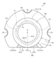
- FIG. 3 is a diagram of the nut of Embodiment 1 viewed from the second direction.
- the second S-shaped groove surface 13b is disposed deviated from the first S-shaped groove surface 13a by 90 degrees in the clockwise direction.
- the third S-shaped groove surface 13c is disposed offset from the second S-shaped groove surface 13b by 90 degrees in the clockwise direction.
- the fourth S-shaped groove surface 13d is disposed offset from the third S-shaped groove surface 13c by 90 degrees in the clockwise direction. Therefore, the four S-shaped groove surfaces 13 are arranged at 90 degree intervals (equally spaced) around the central axis O.
- the first inner peripheral raceway surface 12a of the nut 10 supports the screw shaft 2 from the outside in the radial direction via the balls 8.
- the first S-shaped groove surface 13a connected to the first inner peripheral raceway surface 12a cannot support the screw shaft 2 via the ball 8. Therefore, the first inner circumferential raceway surface 12a cannot support the load in the direction in which the first S-shaped groove surface 13a is arranged (see arrow Y1 in FIG. 3) when viewed from the central axis O.
- the second inner circumferential raceway surface 12b cannot support the load in the direction in which the second S-shaped groove surface 13b is arranged (see arrow Y2 in FIG. 3) when viewed from the central axis O.
- the third inner circumferential raceway surface 12c cannot support the load in the direction in which the third S-shaped groove surface 13c is arranged (see arrow Y3 in FIG. 3) when viewed from the central axis O.
- the fourth inner circumferential raceway surface 12d cannot support the load in the direction in which the fourth S-shaped groove surface 13d is arranged (see arrow Y4 in FIG. 3) when viewed from the central axis O.
- the four S-shaped groove surfaces 13 are distributed in the circumferential direction so that the ranges that cannot be supported from the outside in the radial direction do not overlap. Therefore, the nut 10 supports the screw shaft 2 from all directions in the circumferential direction.
- FIG. 4 is a perspective view of the nut of Embodiment 1 viewed from the second direction.
- the flange 20 includes a partial flange 21 that protrudes radially from the outer circumferential surface 11b of the nut body 11.
- the partial flange 21 does not have an annular shape. That is, the partial flange 21 extends only in a part of the circumferential direction along the outer circumferential surface 11b of the nut main body 11.
- the flange 20 of this embodiment has three partial flanges 21. In other words, the flange 20 is composed of three partial flanges 21.
- the three partial flanges 21 are arranged at equal intervals around the central axis O. That is, the three partial flanges 21 are arranged at intervals of 120 degrees.
- the radially outer surface of the partial flange 21 is provided with a sliding groove surface 22 that is recessed radially inward and opens in the axial direction.
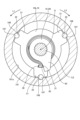
- FIG. 5 is a sectional view taken along the line VV in FIG. 1.
- the radially outer surface of the partial flange 21 faces the inner surface 101a of the housing 101.
- the inner surface 101a is provided with three fixing groove surfaces 106 that are recessed radially outward.
- the fixed groove surface 106 extends in the axial direction (see FIG. 1).
- a portion of a cylindrical shaft 107 extending in the axial direction is housed inside each fixed groove surface 106 .
- a portion of the shaft 107 that protrudes radially inward from the inner surface 101 a of the housing 101 passes through the inside of the sliding groove surface 22 .
- the protrusion 30 protrudes from the second end surface 10b of the nut body 11 in the second direction X2.
- a stopper 60 is arranged in the second direction X2 of the nut 10.
- the stopper 60 has an annular female spline portion 61 spline-fitted to the male spline portion 3 and a protrusion portion 62 that protrudes radially outward from the female spline portion 61 .
- the stopper 60 is configured not to rotate relative to the screw shaft 2. That is, the stopper 60 rotates together with the screw shaft 2.
- the protrusion 62 of the stopper 60 is in contact with the protrusion 30 from the clockwise direction when viewed from the second direction X2.
- the rotation direction of the screw shaft 2 is based on the view from the second direction X2. Specifically, as shown in FIG. 5, when the screw shaft 2 rotates in the left direction (counterclockwise direction) when viewed from the second direction ). Further, when the screw shaft 2 rotates in the right direction (clockwise direction) when viewed from the second direction X2, the rotation direction is referred to as a second rotation direction L2 (see the arrow in FIG. 5). Further, when the screw shaft 2 rotates in the first rotation direction L1, the nut 10 moves in the first direction X1.
- the protrusion 30 has a first contact surface 31 on the side facing the first rotation direction L1.
- the protruding portion 62 of the stopper 60 has a second contact surface 63 on a side surface facing in the second rotation direction L2.
- the piston 50 includes a pressing portion 51 having a disk shape centered on the central axis O, a cylindrical portion 52 extending from the pressing portion 51 in the second direction X2, and an outer peripheral surface 11b of the nut 10. It has a fitting part 53 that fits into the fitting part 53.
- the pressing portion 51 is a portion that presses the liquid within the cylinder 102 in the first direction X1.
- the pressing portion 51 is arranged inside the cylinder 102 and faces the closing wall 104 of the cylinder 102 .
- the inner diameter of the fitting part 53 is larger than the inner diameter of the cylindrical part 52. Therefore, a step surface 54 facing in the second direction X2 is provided between the inner circumferential surface of the cylindrical portion 52 and the inner circumferential surface of the fitting portion 53.
- the stepped surface 54 is in contact with the first end surface 10a of the nut 10. Note that the pressure of the liquid in the cylinder 102 acts on the pressing portion 51, and the piston 50 is constantly pressed in the second direction X2. Therefore, the step surface 54 and the first end surface 10a are always in contact with each other.
- the outer diameters of the cylindrical portion 52 and the fitting portion 53 are slightly smaller than the inner diameter of the cylinder 102. Therefore, a minute gap (not shown) is provided between the outer peripheral surface 50a of the piston 50 and the inner peripheral surface 102a of the cylinder 102. Thereby, when an axial load is applied, the piston 50 moves in the axial direction while sliding on the inner peripheral surface 102a of the cylinder 102.
- Two seal members 108 are provided between the piston 50 and the cylinder 102. This prevents the liquid in the cylinder 102 from passing through the small gap between the piston 50 and the cylinder 102 and leaking in the second direction X2.
- the axial length of the partial flange 21 is shorter than the axial length of the nut body 11. Specifically, the axial length of the partial flange 21 is about the same as the axial length M1 of the track 7 (one lead). Moreover, the partial flange 21 is arranged at the end of the nut body 11 in the second direction X2.
- the partial flange 21 has a side surface 21a facing in the circumferential direction.
- a corner portion 26 is provided at a portion where the side surface 21a and the outer circumferential surface 11b of the nut body 11 intersect.
- an escape space 25 is provided between the side surfaces 21a of each partial flange 21. In other words, three relief spaces 25 are arranged on the outer peripheral side of the nut body 11.
- annular portion 16 a portion of the nut body 11 that is disposed radially inside the flange 20 (a portion that is disposed in the second direction X2 from the broken line H1 in FIG. 2) is referred to as an annular portion 16.
- This annular portion 16 is arranged radially inside the three partial flanges 21 and the three relief spaces 25 .
- a part of the fourth S-shaped groove surface 13d among the four S-shaped groove surfaces 13 is provided on the inner circumferential surface of the annular portion 16.
- the annular portion 16 is divided into three flange connection areas 17 and three flange non-connection areas 18.
- dots are attached to make the range of the flange unconnected region 18 easier to understand.
- the flange connection region 17 is a portion of the annular portion 16 where the partial flange 21 is arranged on the radially outer side and is connected to the partial flange 21 .
- the flange unconnected region 18 is a portion of the annular portion 16 in which a relief space 25 is arranged on the radially outer side and is not connected to the partial flange 21 .
- the flange connection area 17 and the flange unconnection area 18 are divided using a virtual straight line H2 connecting the corner 26 and the central axis O as a boundary line.
- a relief space 25 is arranged on the outside in the radial direction, so that the flesh part of the nut body 11 can escape to the outside in the radial direction by forging.
- the flange unconnected region 18 is a region where the S-shaped groove surface 13 can be formed by forging.
- the fourth S-shaped groove surface 13d is formed on the inner peripheral surface 11a of the flange unconnected region 18 by forging.
- the fourth S-shaped groove surface 13d is disposed closest to the protrusion 30 in the axial direction (see FIG. 2).
- the fourth S-shaped groove surface 13d and the protrusion 30 are arranged deviated from each other by 180 degrees in the circumferential direction. Therefore, even if the contact load from the stopper 60 is input to the protrusion 30, the fourth S-shaped groove surface 13d does not deform. In other words, the ball 8 continues to roll smoothly on the fourth S-shaped groove surface 13d. Further, it is also possible to avoid deformation of the protrusion 30 due to the load when the inner circumferential surface 11a of the nut body 11 is forged. In other words, initial positional deviation is also avoided.
- the ball screw device 1 of Embodiment 1 includes the screw shaft 2, the nut 10, and the plurality of balls 8 arranged between the screw shaft 2 and the nut 10.
- the nut 10 includes a cylindrical nut body 11 that is penetrated by the screw shaft 2, and a plurality of inner circumferential raceway surfaces 12 and a plurality of S-shaped groove surfaces 13 that are recessed radially outward from the inner circumferential surface 11a of the nut body 11. , and a flange 20 protruding radially outward from the outer circumferential surface 11b of the nut body 11.
- the flange 20 is composed of at least one partial flange 21 that extends only partially in the circumferential direction along the outer circumferential surface 11b of the nut main body 11.
- the space is between one end and the other end of the partial flange 21 in the circumferential direction, and when there are two or more partial flanges 21, the space between the circumferentially adjacent partial flanges 21 is , and serves as a relief space 25 through which the flesh of the nut body 11 escapes.
- One S-shaped groove surface 13 (fourth S-shaped groove surface 13d) among the plurality of S-shaped groove surfaces 13 is arranged inside the relief space 25 in the radial direction.
- the nut 10 is lighter than when the flange 20 is annular.
- the plurality of S-shaped groove surfaces 13 are arranged at equal intervals in the circumferential direction.
- the range where the screw shaft 2 cannot be supported from the outside in the radial direction is dispersed in the circumferential direction. Therefore, the nut 10 can support the screw shaft 2 from all circumferential directions.
- the flange 20 has two or more partial flanges 21 arranged at equal intervals in the circumferential direction.
- a shaft 107 is disposed on the radially outer side of the partial flange 21, and is supported by the housing 101 and extends in an axial direction parallel to the screw shaft 2.
- the outer peripheral surface of the partial flange 21 is provided with a sliding groove surface 22 that is recessed radially inward and in which a shaft is accommodated.
- the nut 10 is supported by the housing 101 so as to be non-rotatable and movable in the axial direction.
- one end surface (second end surface 10b) of the nut main body 11 is provided with a protrusion 30 that protrudes in the axial direction and comes into contact with a stopper 60 that does not rotate relative to the screw shaft 2.
- the S-shaped groove surface 13 (fourth S-shaped groove surface 13d) that is disposed closest to the protrusion in the axial direction is disposed offset from the protrusion 30 in the circumferential direction.
- the fourth S-shaped groove surface 13d and the protrusion 30 are separated from each other. Therefore, even if a contact load with the stopper 60 is input to the protrusion 30, the fourth S-shaped groove surface 13d does not deform.
- Embodiment 1 has been described above, the present disclosure is not limited to the example shown in Embodiment 1.
- the fourth S-shaped groove surface 13d and the protrusion 30 are spaced apart by 180 degrees, but the present disclosure is not limited thereto. It is sufficient that the fourth S-shaped groove surface 13d and the protrusion 30 do not overlap when viewed from the axial direction, and for example, the fourth S-shaped groove surface 13d and the protrusion 30 may be spaced apart by about 30 degrees. Further, the present disclosure may be a nut 10 that does not have the protrusion 30.
- the sliding groove surface 22 was provided on the outer peripheral surface of the partial flange 21 in order to prevent the nut 10 from rotating, but the present disclosure is not limited to this.
- the partial flange 21 itself may fit into the fixing groove surface 106.
- a protrusion may be provided on the outer peripheral surface of the partial flange 21 so that the protrusion enters the fixing groove surface 106 of the housing 101.
- the protrusion provided on the outer peripheral surface of the partial flange 21 may be either integral with the partial flange 21 or separate (separate part from the partial flange 21).
- FIG. 6 is a diagram of the nut of Modification 1 viewed from the second direction.
- the nut 10A of the first modification differs from the nut 10 of the first embodiment in that it has a flange 20A instead of the flange 20.
- the flange 20A has one partial flange 21A. Therefore, there is only one space (escape space 25A) between the one end 21b and the other end 21c in the circumferential direction of the partial flange 21A.
- the annular portion 16A is divided into one flange connection area 17A and one flange unconnected area 18A.
- a fourth S-shaped groove surface 13d is provided in the flange unconnected region 18A that can be forged.
- the partial flange 21A has a longer length in the circumferential direction than the partial flange 21 of the first embodiment. Specifically, the angle ⁇ from one end 21b to the other end 21c of the partial flange 21A is about 300 degrees. Three sliding groove surfaces 22 are provided on the outer peripheral surface of the partial flange 21A. According to this partial flange 21A, the rigidity is higher than that of the partial flange 21 of the first embodiment, and it is difficult to deform. Therefore, it is avoided that the partial flange 21A is deformed and its slidability with respect to the shaft 107 is impaired.
- Modification 1 has been described above, but as shown in Modification 1, the present disclosure is not particularly limited regarding the circumferential length of the partial flanges or the number of partial flanges.
- FIG. 7 is a diagram of the flange-unconnected region of the nut of Modification 2 viewed from the second direction. As shown in FIG. 7, the nut 10B of the second modification differs from the nut 10 of the first embodiment in that a portion of the fourth S-shaped groove surface 13d is provided in the flange connection region 17B.
- the central portion of the S-shaped groove surface 13 in the length direction is a bottom surface 14a that is recessed most outward in the radial direction.
- Both ends of the S-shaped groove surface 13 in the length direction are inclined surfaces 14b and 14c in which the amount of depression gradually increases as it approaches the bottom surface 14a.
- the length direction of the S-shaped groove surface 13 is a direction along the S-shaped groove surface 13, and is also referred to as a direction along the S-shape. Furthermore, during forging, a large amount of flesh escapes radially outward due to the shaping of the bottom surface 14a.
- the amount of flesh that escapes radially outward due to the formation of the inclined surfaces 14b and 14c is smaller than that of the bottom surface 14a.
- a portion of the inclined surfaces 14b and 14c (a portion continuous to the inner raceway surface 12) of the S-shaped groove surface 13 is provided in the flange connection region 17B.
- the remaining portions of the inclined surfaces 14b and 14c (portions continuous to the bottom surface 14) and the bottom surface 14a are provided in the flange unconnected region 18B (radially inside the escape space 25B).
- the flange connection region 17B may be formed as shown in Modification Example 2.
- the present disclosure does not have the restriction that the entire S-shaped groove surface 13 must be formed into the flange-unconnected region 18B as shown in Modification 2, and has a high degree of freedom in the layout of the S-shaped groove surface 13. is high.
- groove surfaces (slope surfaces 14b, 14c) that can be formed in the flange connection region 17B are groove surfaces with a depression amount of 50% or less, preferably 20%, of the maximum depression amount N (see FIG. 7) of the bottom surface 14a. It is limited to groove surfaces with the following depression amounts.
- FIG. 8 is a perspective view of the nut of Modification Example 3 viewed from the second direction.
- FIG. 9 is a diagram of the nut of Modification 3 viewed from the second direction.
- FIG. 10 is an enlarged view of a part of FIG. 9.
- modification 3 an example will be described in which the second end surface 10b of the nut 10E protrudes further in the second direction X2 than the flange 20E (partial flange 21E). That is, the flange 20E (partial flange 21E) of the third modification is arranged slightly closer to the first direction X1 than the end of the nut main body 11 in the second direction X2.
- the flange 20E may be arranged at the end of the nut body 11 in the second direction X2.
- the sliding groove surfaces 22 of Modification 3 are not arranged at equal intervals in the circumferential direction, in the present disclosure, the sliding groove surfaces 22 may be arranged at equal intervals in the circumferential direction.
- the flange 20E of the nut 10E of Modification 3 is common to the partial flange 21A of Modification 1 (see FIG. 6) in that there is one partial flange 21E. In other words, there is only one escape space 25E in the third modification.
- the partial flange 21E of Modification Example 3 is different from the partial flange of Modification Example 1 in that it is D-shaped when viewed from the axial direction. That is, in the partial flange 21E of the third modification, the side surface 121b located at one end 21b in the circumferential direction and the side surface 121c located at the other end 21c in the circumferential direction are linearly connected. Therefore, the relief space 25E of the third modification is a space extending in the circumferential direction between the one end 21b and the other end 21c of the partial flange 21E in the circumferential direction.
- a linear side surface that is a combination of the side surfaces 121b and 121c will be referred to as a linear side surface 121.
- an imaginary straight line connecting the contact point P121 between the linear side surface 121 and the outer circumferential surface 11b and the central axis O will be referred to as an imaginary line H121.
- the distance H3 between the outer peripheral surface 11b of the annular portion 16 and the straight side surface 121 becomes smaller as it approaches the contact point P121.
- the portion of the partial flange 21E where the linear side surface 121 is provided becomes thinner in the radial direction as it approaches the contact point P121.
- the thickness of the partial flange 21E in the radial direction is H4.
- a portion of the partial flange 21E whose radial thickness is 1/2 or less of H4 will be referred to as an incomplete flange 121E (see the dotted area in FIG. 9).
- the flange unconnected region 18 (the part of the annular part 16 in which the relief space 25 is arranged on the outside in the radial direction and is not connected to the partial flange 21) is the annular part 16. 16, which overlaps with the virtual line H121.
- the fourth S-shaped groove surface 13d among the four S-shaped groove surfaces 13 is arranged in the annular portion 16.
- the bottom surface 14 a of the fourth S-shaped groove surface 13 d that is recessed most radially outward is located in the flange unconnected region 18 . Therefore, the bottom surface 14a of the fourth S-shaped groove surface 13d can allow many of the flesh portions of the nut body 11 to escape radially outward by forging.
- the inclined surfaces 14b and 14c of the fourth S-shaped groove surface 13d are arranged in the flange connection region 17.
- the portion disposed on the radially outer side of the flange connection region 17 is an incomplete flange 121E having a small radial thickness. Therefore, the flesh portions for forming the inclined surfaces 14b and 14c can escape radially outward. From the above, the fourth S-shaped groove surface 13d can be formed by forging.
- the straight side surface 121 is a tangent to the outer peripheral surface 11b of the annular portion 16; however, in the present disclosure, the straight side surface 121 may be a tangent to the outer peripheral surface 11b of the annular portion 16. good.
- the linear side surface 121 is arranged radially outward from the outer circumferential surface 11b of the annular portion 16, and there may be no intersection between the linear side surface 121 and the outer circumferential surface 11b (see nut 10F in FIG. 12).
- the annular portion 16 does not have the flange-unconnected region 18 and is entirely comprised of only the flange-connected region 17.
- the portion disposed on the radially outer side of the S-shaped groove surface 13 is an incomplete flange 121E, the S-shaped groove surface 13 can be formed by forging.
- the linear side surface 121 and the outer circumferential surface 11b of the annular portion 16 may have two intersections.
- the linear side surface 121 may cut out a part of the outer circumferential surface 11b of the annular portion 16, so that the outer circumferential surface 11b of the annular portion 16 has a D-shape when viewed from the axial direction.
- the end portion in the length direction of the S-shaped groove surface 13 (the entrance/exit of the S-shaped groove surface 13) is arranged inside the incomplete flange 121E in the radial direction;
- the longitudinal ends of the grooved surfaces 13 do not need to be arranged on the radially inner side of the incomplete flange 121E.
- the groove surface has a recess amount of 50% or less with respect to the maximum recess amount N (see FIG. 7) of the bottom surface 14a, the partial flange 20E (excluding the range of the incomplete flange 121E) This is because it is possible to mold even if it is placed radially inside.
- a partial flange having one straight side surface 121 is taken as an example, but in the present disclosure, the partial flange has two straight side surfaces 121, and the two straight side surfaces 121 are mutually connected to each other. Partial flanges that are parallel may also be used. That is, the present disclosure may be a partial flange having a plurality of straight side surfaces 121. Further, although the partial flange of Modification 3 is provided with the sliding groove surface 22 and is used as a rotation stopper, the present disclosure may be used for other purposes.
- Embodiment 1 and its modifications have been described above.
- the partial flanges of Embodiment 1 and the modified example are used to prevent rotation of the nut, the present disclosure is not limited thereto.
- Next, an example in which the partial flange is used for purposes other than rotation prevention will be described.
- FIG. 11 is a perspective view of the nut of Embodiment 2 viewed from the second direction.
- the second embodiment is similar to the first embodiment in that the flange 20C of the nut 10C has three partial flanges 21C.
- the partial flange 21C is different from the partial flange 21 of the first embodiment in that the sliding groove surface 22 that is penetrated by the shaft 107 is not provided.
- the partial flange 21C is different from the partial flange 21 of the first embodiment in that a through hole 24 that penetrates in the axial direction is provided in the partial flange 21C.
- the nut 10C is arranged to face the planetary gear 114 of the planetary gear mechanism 110 in the axial direction.
- the transmission shaft 115 (see FIG. 1) of the planetary gear mechanism 110 is inserted into the through hole 24 of the partial flange 21C. Therefore, the rotational motion of the planetary gear 114 that rotates (revolutions) about the central axis O is input to the three partial flanges 21C, and the nut 10C rotates.
- the three partial flanges 21C of the second embodiment are used as the carrier 116 (see FIG. 1) of the planetary gear mechanism 110.
- the carrier 116 becomes unnecessary, and the number of parts can be reduced.
- the nut 10C rotates and the screw shaft 2 moves in the axial direction.
- the hole provided in the partial flange 21C is a through hole 24, but it may be a blind hole (a hole that does not pass through).
- the through hole 24 is applied to the nut 10C having a plurality of (three) partial flanges 21C, but the present disclosure is not limited thereto.
- the through hole 24 may be provided in the nut 10A having the partial flange 21A shown in Modification 1.
- FIG. 12 is a diagram of a nut of modification 4 viewed from the second direction.
- the flange 20F of the nut 10F of the fourth modification is a D-shaped partial flange 21F having an incomplete flange 121E, as shown in the third modification.
- a through hole 24 may be provided in this D-shaped partial flange 21F.
- FIG. 13 is a perspective view of the nut of Embodiment 3 viewed from the second direction.
- FIG. 14 is a diagram of the nut of Embodiment 3 viewed from the second direction.
- the nut 10D of the third embodiment differs from the nut 10 of the first embodiment in that there are two partial flanges 21D.
- the two partial flanges 21D are arranged symmetrically with respect to the central axis O. In other words, the two partial flanges 21D are arranged 180 degrees apart in the circumferential direction. Therefore, in the third embodiment, two escape spaces 25D are provided.
- the axial length of the partial flange 21D is the same as the axial length of the nut body 11. As shown in FIG. 14, the nut 10D is inserted into the inner peripheral side of the driven pulley 200. Furthermore, the partial flange 21D fits into a groove 220 provided in the inner peripheral surface 210 of the driven pulley 200. When power is transmitted from the belt 230 to the driven pulley 200, the nut 10D rotates together with the driven pulley 200, and the screw shaft 2 (see FIG. 1) moves in the axial direction. As described above, the two partial flanges 21D of the third embodiment are used as a rotation stopper to restrict relative rotation with respect to the driven pulley 200.
- the entire nut body 11 in the axial direction is the annular portion 16.
- all four S-shaped groove surfaces 13 are arranged radially inside the two partial flanges 21D and the two relief spaces 25D.
- the annular portion 16 is divided into two flange-connected regions 17D and two flange-unconnected regions 18D.
- the four S-shaped groove surfaces 13 (first S-shaped groove surface 13a, second S-shaped groove surface 13b, third S-shaped groove surface 13c, and fourth S-shaped groove surface 13d) are arranged at 90-degree intervals as in the first embodiment. has been done. All of the four S-shaped groove surfaces 13 are provided on the inner circumferential surface 11a of the flange unconnected region 18D. In this manner, in the third embodiment as well, there is no need to perform molding by shifting the S-shaped groove surface 13 in the axial direction with respect to the flange 20D (partial flange 21D). Therefore, it is possible to avoid increasing the size of the nut 10 in the axial direction.
- the present disclosure is not limited to the example shown in the embodiment, as long as at least one or more S-shaped groove surfaces 13 among the plurality of S-shaped groove surfaces 13 are arranged inside the relief space 25 in the radial direction. .
- the outer diameter of the nut main body 11 and the outer diameter of the annular portion 16 may not be the same. That is, the outer diameter of the annular portion 16 may be larger or smaller than the outer diameter of the nut body 11.
- the present disclosure may be a combination of the following configurations.
- the nut according to (1) is a relief space that allows the flesh of the nut body to escape;
- the nut wherein one of the plurality of S-shaped groove surfaces is disposed inside the relief space in the radial direction.
- the nut according to (1) wherein the plurality of S-shaped groove surfaces are arranged at equal intervals in the circumferential direction.
- the flange has two or more partial flanges arranged at equal intervals in the circumferential direction.
- a shaft supported by a housing and extending in an axial direction parallel to the screw shaft is disposed on the radially outer side of the partial flange,
- the planetary gear of the planetary gear mechanism and the partial flange face each other in an axial direction parallel to the screw shaft, The nut according to any one of (1) to (3), wherein the partial flange is provided with a hole into which a transmission shaft that supports the planetary gear is inserted.
- the nut body is arranged inside the driven pulley, The nut according to any one of (1) to (3), wherein the partial flange is inserted into a groove provided on the inner peripheral surface of the driven pulley.
- One end surface of the nut body is provided with a protrusion that protrudes in the axial direction and comes into contact with a stopper that does not rotate relative to the screw shaft, Of (1) to (6), the S-shaped groove surface that is disposed closest to the protrusion in the axial direction among the plurality of S-shaped groove surfaces is disposed offset in the circumferential direction with respect to the protrusion. Any one of the nuts listed.
Landscapes
- Engineering & Computer Science (AREA)
- General Engineering & Computer Science (AREA)
- Mechanical Engineering (AREA)
- Transmission Devices (AREA)
Priority Applications (4)
| Application Number | Priority Date | Filing Date | Title |
|---|---|---|---|
| CN202380039894.2A CN119173704A (zh) | 2022-09-08 | 2023-08-24 | 螺母和滚珠丝杠装置 |
| JP2023574846A JP7477062B1 (ja) | 2022-09-08 | 2023-08-24 | ナット及びボールねじ装置 |
| US19/108,201 US20260063189A1 (en) | 2022-09-08 | 2023-08-24 | Nut and ball screw device |
| DE112023002959.8T DE112023002959T5 (de) | 2022-09-08 | 2023-08-24 | Mutter und kugelgewindetrieb |
Applications Claiming Priority (2)
| Application Number | Priority Date | Filing Date | Title |
|---|---|---|---|
| JP2022142738 | 2022-09-08 | ||
| JP2022-142738 | 2022-09-08 |
Publications (1)
| Publication Number | Publication Date |
|---|---|
| WO2024053415A1 true WO2024053415A1 (ja) | 2024-03-14 |
Family
ID=90191220
Family Applications (1)
| Application Number | Title | Priority Date | Filing Date |
|---|---|---|---|
| PCT/JP2023/030514 Ceased WO2024053415A1 (ja) | 2022-09-08 | 2023-08-24 | ナット及びボールねじ装置 |
Country Status (5)
| Country | Link |
|---|---|
| US (1) | US20260063189A1 (https=) |
| JP (1) | JP7477062B1 (https=) |
| CN (1) | CN119173704A (https=) |
| DE (1) | DE112023002959T5 (https=) |
| WO (1) | WO2024053415A1 (https=) |
Citations (3)
| Publication number | Priority date | Publication date | Assignee | Title |
|---|---|---|---|---|
| JP2014092223A (ja) * | 2012-11-05 | 2014-05-19 | Nsk Ltd | ボールねじ装置及びボールねじ装置を備えた直動アクチュエータ |
| JP2019014358A (ja) * | 2017-07-06 | 2019-01-31 | 株式会社ジェイテクト | ステアリング装置及びステアリング装置の製造方法 |
| JP2021095924A (ja) * | 2019-12-13 | 2021-06-24 | 日本精工株式会社 | ボールねじのナット及びボールねじのナットの製造方法 |
Family Cites Families (2)
| Publication number | Priority date | Publication date | Assignee | Title |
|---|---|---|---|---|
| JP3111878U (ja) * | 2005-04-13 | 2005-07-28 | 茂▲どうん▼ 李 | ボールねじの内循環器構造 |
| JP6456036B2 (ja) * | 2014-04-15 | 2019-01-23 | 日本電産サンキョー株式会社 | モータ |
-
2023
- 2023-08-24 CN CN202380039894.2A patent/CN119173704A/zh active Pending
- 2023-08-24 US US19/108,201 patent/US20260063189A1/en active Pending
- 2023-08-24 WO PCT/JP2023/030514 patent/WO2024053415A1/ja not_active Ceased
- 2023-08-24 JP JP2023574846A patent/JP7477062B1/ja active Active
- 2023-08-24 DE DE112023002959.8T patent/DE112023002959T5/de active Pending
Patent Citations (3)
| Publication number | Priority date | Publication date | Assignee | Title |
|---|---|---|---|---|
| JP2014092223A (ja) * | 2012-11-05 | 2014-05-19 | Nsk Ltd | ボールねじ装置及びボールねじ装置を備えた直動アクチュエータ |
| JP2019014358A (ja) * | 2017-07-06 | 2019-01-31 | 株式会社ジェイテクト | ステアリング装置及びステアリング装置の製造方法 |
| JP2021095924A (ja) * | 2019-12-13 | 2021-06-24 | 日本精工株式会社 | ボールねじのナット及びボールねじのナットの製造方法 |
Also Published As
| Publication number | Publication date |
|---|---|
| CN119173704A (zh) | 2024-12-20 |
| JP7477062B1 (ja) | 2024-05-01 |
| US20260063189A1 (en) | 2026-03-05 |
| JPWO2024053415A1 (https=) | 2024-03-14 |
| DE112023002959T5 (de) | 2025-04-24 |
Similar Documents
| Publication | Publication Date | Title |
|---|---|---|
| CN103782491B (zh) | 带减速机的马达 | |
| EP2520829A1 (en) | Linear actuator | |
| KR101681247B1 (ko) | 휨맞물림식 기어장치 | |
| EP2833022B1 (en) | Ball screw device | |
| WO2020084936A1 (ja) | 無段変速機 | |
| CN105822726B (zh) | 减速机构和带减速机的驱动装置 | |
| KR101644955B1 (ko) | 휨맞물림식 기어장치 | |
| WO2023145595A1 (ja) | ボールねじ装置 | |
| JP7316828B2 (ja) | 減速機 | |
| WO2024053415A1 (ja) | ナット及びボールねじ装置 | |
| WO2018096939A1 (ja) | 電動アクチュエータ | |
| KR102534827B1 (ko) | 회전식 감속 액추에이터 | |
| JP2024058020A (ja) | ボールねじ装置 | |
| JP7494789B2 (ja) | 減速機付モータ | |
| JP5974600B2 (ja) | 直動アクチュエータおよびこれを備えた電動ブレーキ | |
| JP7838401B2 (ja) | ボールねじ装置 | |
| CN118265858A (zh) | 滚珠丝杠装置 | |
| JP6990323B2 (ja) | 無段変速機 | |
| JP7838402B2 (ja) | ボールねじ装置 | |
| JP7392903B1 (ja) | 直動アクチュエータ | |
| WO2022176681A1 (ja) | 伝動装置 | |
| KR102451189B1 (ko) | 자동차의 감속기 | |
| JP7764797B2 (ja) | 電動アクチュエータ | |
| JP2024055480A (ja) | 電動アクチュエータ | |
| JP7563654B1 (ja) | アクチュエータ |
Legal Events
| Date | Code | Title | Description |
|---|---|---|---|
| ENP | Entry into the national phase |
Ref document number: 2023574846 Country of ref document: JP Kind code of ref document: A |
|
| 121 | Ep: the epo has been informed by wipo that ep was designated in this application |
Ref document number: 23862954 Country of ref document: EP Kind code of ref document: A1 |
|
| WWE | Wipo information: entry into national phase |
Ref document number: 112023002959 Country of ref document: DE |
|
| WWP | Wipo information: published in national office |
Ref document number: 112023002959 Country of ref document: DE |
|
| 122 | Ep: pct application non-entry in european phase |
Ref document number: 23862954 Country of ref document: EP Kind code of ref document: A1 |