EP2520829A1 - Linear actuator - Google Patents
Linear actuator Download PDFInfo
- Publication number
- EP2520829A1 EP2520829A1 EP11774635A EP11774635A EP2520829A1 EP 2520829 A1 EP2520829 A1 EP 2520829A1 EP 11774635 A EP11774635 A EP 11774635A EP 11774635 A EP11774635 A EP 11774635A EP 2520829 A1 EP2520829 A1 EP 2520829A1
- Authority
- EP
- European Patent Office
- Prior art keywords
- guide
- ball screw
- motion component
- projection
- linear motion
- Prior art date
- Legal status (The legal status is an assumption and is not a legal conclusion. Google has not performed a legal analysis and makes no representation as to the accuracy of the status listed.)
- Granted
Links
Images


Classifications
-
- F—MECHANICAL ENGINEERING; LIGHTING; HEATING; WEAPONS; BLASTING
- F16—ENGINEERING ELEMENTS AND UNITS; GENERAL MEASURES FOR PRODUCING AND MAINTAINING EFFECTIVE FUNCTIONING OF MACHINES OR INSTALLATIONS; THERMAL INSULATION IN GENERAL
- F16H—GEARING
- F16H25/00—Gearings comprising primarily only cams, cam-followers and screw-and-nut mechanisms
- F16H25/18—Gearings comprising primarily only cams, cam-followers and screw-and-nut mechanisms for conveying or interconverting oscillating or reciprocating motions
- F16H25/20—Screw mechanisms
- F16H2025/204—Axial sliding means, i.e. for rotary support and axial guiding of nut or screw shaft
-
- F—MECHANICAL ENGINEERING; LIGHTING; HEATING; WEAPONS; BLASTING
- F16—ENGINEERING ELEMENTS AND UNITS; GENERAL MEASURES FOR PRODUCING AND MAINTAINING EFFECTIVE FUNCTIONING OF MACHINES OR INSTALLATIONS; THERMAL INSULATION IN GENERAL
- F16H—GEARING
- F16H25/00—Gearings comprising primarily only cams, cam-followers and screw-and-nut mechanisms
- F16H25/18—Gearings comprising primarily only cams, cam-followers and screw-and-nut mechanisms for conveying or interconverting oscillating or reciprocating motions
- F16H25/20—Screw mechanisms
- F16H2025/2062—Arrangements for driving the actuator
- F16H2025/2081—Parallel arrangement of drive motor to screw axis
-
- F—MECHANICAL ENGINEERING; LIGHTING; HEATING; WEAPONS; BLASTING
- F16—ENGINEERING ELEMENTS AND UNITS; GENERAL MEASURES FOR PRODUCING AND MAINTAINING EFFECTIVE FUNCTIONING OF MACHINES OR INSTALLATIONS; THERMAL INSULATION IN GENERAL
- F16H—GEARING
- F16H25/00—Gearings comprising primarily only cams, cam-followers and screw-and-nut mechanisms
- F16H25/18—Gearings comprising primarily only cams, cam-followers and screw-and-nut mechanisms for conveying or interconverting oscillating or reciprocating motions
- F16H25/20—Screw mechanisms
- F16H25/2015—Means specially adapted for stopping actuators in the end position; Position sensing means
-
- F—MECHANICAL ENGINEERING; LIGHTING; HEATING; WEAPONS; BLASTING
- F16—ENGINEERING ELEMENTS AND UNITS; GENERAL MEASURES FOR PRODUCING AND MAINTAINING EFFECTIVE FUNCTIONING OF MACHINES OR INSTALLATIONS; THERMAL INSULATION IN GENERAL
- F16H—GEARING
- F16H25/00—Gearings comprising primarily only cams, cam-followers and screw-and-nut mechanisms
- F16H25/18—Gearings comprising primarily only cams, cam-followers and screw-and-nut mechanisms for conveying or interconverting oscillating or reciprocating motions
- F16H25/20—Screw mechanisms
- F16H25/22—Screw mechanisms with balls, rollers, or similar members between the co-operating parts; Elements essential to the use of such members
- F16H25/2204—Screw mechanisms with balls, rollers, or similar members between the co-operating parts; Elements essential to the use of such members with balls
- F16H25/2214—Screw mechanisms with balls, rollers, or similar members between the co-operating parts; Elements essential to the use of such members with balls with elements for guiding the circulating balls
-
- Y—GENERAL TAGGING OF NEW TECHNOLOGICAL DEVELOPMENTS; GENERAL TAGGING OF CROSS-SECTIONAL TECHNOLOGIES SPANNING OVER SEVERAL SECTIONS OF THE IPC; TECHNICAL SUBJECTS COVERED BY FORMER USPC CROSS-REFERENCE ART COLLECTIONS [XRACs] AND DIGESTS
- Y10—TECHNICAL SUBJECTS COVERED BY FORMER USPC
- Y10T—TECHNICAL SUBJECTS COVERED BY FORMER US CLASSIFICATION
- Y10T74/00—Machine element or mechanism
- Y10T74/18—Mechanical movements
- Y10T74/18568—Reciprocating or oscillating to or from alternating rotary
- Y10T74/18576—Reciprocating or oscillating to or from alternating rotary including screw and nut
- Y10T74/18648—Carriage surrounding, guided by, and primarily supported by member other than screw [e.g., linear guide, etc.]
-
- Y—GENERAL TAGGING OF NEW TECHNOLOGICAL DEVELOPMENTS; GENERAL TAGGING OF CROSS-SECTIONAL TECHNOLOGIES SPANNING OVER SEVERAL SECTIONS OF THE IPC; TECHNICAL SUBJECTS COVERED BY FORMER USPC CROSS-REFERENCE ART COLLECTIONS [XRACs] AND DIGESTS
- Y10—TECHNICAL SUBJECTS COVERED BY FORMER USPC
- Y10T—TECHNICAL SUBJECTS COVERED BY FORMER US CLASSIFICATION
- Y10T74/00—Machine element or mechanism
- Y10T74/18—Mechanical movements
- Y10T74/18568—Reciprocating or oscillating to or from alternating rotary
- Y10T74/18576—Reciprocating or oscillating to or from alternating rotary including screw and nut
- Y10T74/18656—Carriage surrounded, guided, and primarily supported by member other than screw [e.g., linear guide, etc.]
-
- Y—GENERAL TAGGING OF NEW TECHNOLOGICAL DEVELOPMENTS; GENERAL TAGGING OF CROSS-SECTIONAL TECHNOLOGIES SPANNING OVER SEVERAL SECTIONS OF THE IPC; TECHNICAL SUBJECTS COVERED BY FORMER USPC CROSS-REFERENCE ART COLLECTIONS [XRACs] AND DIGESTS
- Y10—TECHNICAL SUBJECTS COVERED BY FORMER USPC
- Y10T—TECHNICAL SUBJECTS COVERED BY FORMER US CLASSIFICATION
- Y10T74/00—Machine element or mechanism
- Y10T74/18—Mechanical movements
- Y10T74/18568—Reciprocating or oscillating to or from alternating rotary
- Y10T74/18576—Reciprocating or oscillating to or from alternating rotary including screw and nut
- Y10T74/1868—Deflection related
-
- Y—GENERAL TAGGING OF NEW TECHNOLOGICAL DEVELOPMENTS; GENERAL TAGGING OF CROSS-SECTIONAL TECHNOLOGIES SPANNING OVER SEVERAL SECTIONS OF THE IPC; TECHNICAL SUBJECTS COVERED BY FORMER USPC CROSS-REFERENCE ART COLLECTIONS [XRACs] AND DIGESTS
- Y10—TECHNICAL SUBJECTS COVERED BY FORMER USPC
- Y10T—TECHNICAL SUBJECTS COVERED BY FORMER US CLASSIFICATION
- Y10T74/00—Machine element or mechanism
- Y10T74/18—Mechanical movements
- Y10T74/18568—Reciprocating or oscillating to or from alternating rotary
- Y10T74/18576—Reciprocating or oscillating to or from alternating rotary including screw and nut
- Y10T74/18688—Limit stop
Definitions
- the present invention relates to a linear actuator equipped with a ball screw mechanism for converting a rotational motion transmitted to a rotational motion component into a linear motion.
- a linear actuator of this kind has a ball screw mechanism with a ball screw shaft and a ball screw nut screwed via a lot of balls into the ball screw shaft.
- one of the ball screw shaft and the ball screw nut is defined as a rotational motion component for rotational driving
- the other of the ball screw shaft and the ball screw nut is defined as a linear motion component for linear motion.
- a detent is generally attained by engaging a guide projection provided in the linear motion component into a guide groove formed in an axial direction in a securing portion.
- an electric actuator including a ball screw mechanism composed of a nut supported via a rolling bearing mounted on housing movably and not movably in an axial direction; and a ball screw shaft arranged at the interior of the nut via a lot of balls and coaxially integrated with a driving shaft (see Patent Document 1).
- the electric actuator has a cylindrical sac hole having a flat surface facing each other the housing.
- a detent member is formed in a rectangular form having a flat surface to be engaged to the flat surface, and movably inserted into the sac hole in an axial direction.
- a spiral rib is provided on an inner peripheral surface of the detent member. The rib is engaged into a screw groove to hold the screw shaft unrotatably with respect to the housing and movably in an axial direction.
- a stopper is provided in the rotational motion component and the linear motion component to restrict stroke in an axial direction of the linear motion component in the rotational motion component and the linear motion component, in order to prevent come-off from a screwed state of the both.
- a ball screw device in which a nut member and a bracket with a C-shaped section to which a rotational driving force is transmitted are integrally provided.
- a screw shaft securely disposed via balls is screwed with a nut member, a stopper pin is provided in the screw shaft and a cutout is formed in the bracket.
- a ball screw-type feeder comprising: an inner member on an outer periphery of which a spiral groove raceway is formed; an outer member on an inner periphery of which a spiral groove is formed; a plurality of balls inserted between the two spiral grooves; and an annular cage in which plural pockets are formed to hold the balls, wherein a stopper is provided to engage at least on an end of the spiral groove raceway of the inner member or on an end of the spiral groove raceway of the outer member in a circumferential direction with respect to the cage to restrict movement of the cage in an axial direction (see e..g.. Patent Document 3).
- an electric actuator in which a flat surface is formed in a large-diameter portion of a ball screw nut.
- a cam follower is installed in a protruding manner toward the outside in an axial direction at substantially the center of the flat surface.
- An end of the cam follower is rotatably and slidably fitted in the cutout of the housing for suppressing rotation of the ball screw nut, with the rotation of the ball screw shaft (see e.g. Patent Document 4).
- a detent mechanism is provided to suppress simultaneous rotation caused by torque due to the rotational motion component.
- a ball screw including a screw shaft screwed via balls into a nut, wherein a detent member provided in the nut is engaged into a guide groove formed in the housing (see e.g. Patent Document. 5).
- an actuator in which a pin secured to the housing is engaged via a bush, serving as a friction reduction member, into a groove formed in a nut (see e.g. Patent Document 6).
- an electric actuator in which a flat surface is formed in a large-diameter portion of a ball screw nut.
- a cam follower is installed in a protruding manner toward the outside in an axial direction at substantially the center of the flat surface, and an end of the cam follower is rotatably and slidably fitted in a cutout of housing to restrict rotation of the ball screw nut, with the rotation of the ball screw shaft (see e.g. Patent Document 7).
- a ball screw shaft 101 is screwed via balls (not shown) into a ball screw nut 100 to be rotatably driven, a locking projection 102 proximate to the ball screw nut 100 at the stroke end is provided in the ball screw shaft 101, and a locking piece 103 to be locked with the locking projection 102 is provided in the ball screw nut 100.
- a guide projection 104 is provided in a protruding manner at the opposite side of the locking projection 102 with respect to the ball screw nut 100. The guide projection 104 is engaged into a guide groove 105 formed in a securing portion along the ball screw shaft 101 for enabling the detent function.
- the detent member is engaged in an abutment portion of the cutout constituting a guide section of the housing.
- the detent slidingly contacts with the abutment portion of the cutout, thereby generating large contact resistance between the detent member and the abutment portion and frictional wear.
- Patent Document 6 In order to reduce the contact resistance and the frictional wear, in the prior art disclosed in Patent Document 6, it takes steps to reduce the contact resistance between the groove and the projection for suppressing the frictional wear by using a friction reduction member.
- a predetermined gap is normally arranged between the groove and the projection in consideration of variability in assembling and processing performance. Therefore, even when the projection abuts with a groove side wall, the projection and the groove side wall comes into contact with each other at an angle forming a point contact (or line contact), giving rise to high contact pressure at a contact point. There is an unsolved problem that it leads to uneven abrasion and an increased rattle, even for long-term use.
- a first object of the present invention is to provide a linear actuator the structure of which can be simplified by adding a stopper function to a detent mechanism, and in addition, to prevent the occurrence of radial load.
- a second object of the present invention is to provide a linear actuator in which uneven wear can be suppressed without the provision of a cam follower.
- a first aspect of a linear actuator according to the present invention including a rotational motion component and a linear motion component, and comprising a ball screw mechanism to convert a rotational motion transmitted to the rotational motion component into a linear motion
- the ball screw mechanism has a guide projection projecting in a radial direction and provided in the linear motion component, and a guide groove engaged with the guide projection and disposed in a securing portion facing the linear motion component to guide the guide projection in an axial direction, and has a structure to make the linear motion component subject not to rotate
- the guide projection has a projection projecting by a predetermined length from the guide groove, while engaging into the guide groove, at a stroke end of the linear motion component, and locks a locking portion provided in the rotational motion component to lock to the projection of the guide projection.
- a second aspect of the linear actuator according to the present invention in the first aspect, the axial length of the guide projection may be set longer than a lead of the ball screw mechanism.
- the locking portion may be integrally provided in the rotational motion component, may be formed before grooving of at least one of a ball screw groove and a circulating groove of the rotational motion component, and may be established as a reference for processing for at least one of the ball screw groove and the circulating groove.
- a fourth aspect of the linear actuator according to the present invention includes a rotational motion component and a linear motion component, and comprising a ball screw mechanism to convert a rotational motion transmitted to the rotational motion component into a linear motion
- the ball screw mechanism has a guide projection projecting in a radial direction and provided in the linear motion component, and a guide groove engaged with the guide projection and disposed in a securing portion facing the linear motion component to guide the guide projection in an axial direction, and has a structure to make the linear motion component subject not to rotate
- the guide groove is formed in a guide member having a cylindrical outer peripheral surface in the axial direction, and the guide member is rotatably held in a support hole formed in the axial direction at a position, facing the linear motion component, of the securing portion.
- the guide member may have a cross-sectional shape having an angle greater than a semicircle, and the support hole has a cross- sectional shape having an angle greater than a semicircle.
- the guide member may be formed of a cylindrical surface having an angle greater than a semicircle and a plane connecting an end of the cylindrical surface, and the guide groove is formed in the plane.
- the guide member may be formed by cutting a long member manufactured by drawing to a predetermined length.
- an external form of the guide member may be formed of a large-diameter portion and a small-diameter portion, and the support hole may have a large-diameter hole and a small-diameter hole respectively engaging to the large-diameter portion and the small-diameter portion of the guide member, and a tapered portion connecting the large-diameter hole to the small-diameter hole.
- the guide member may be manufactured by a sintered product.
- a tenth aspect of the linear actuator according to the present invention, in one of fourth to ninth, a surface treatment may be applied to the guide member for improving a wear resistance and slidability.
- the guide member may have on the cylindrical surface a concave groove to be engaged in a circumferential direction with a projecting rib formed on an inner peripheral surface of the support hole.
- the guide projection may have a projection projecting by a predetermined length, while engaging in the guide groove at a stroke end of the linear motion component, and a locking portion provided in the rotational motion component is locked to the projection.
- a pair of the guide projections may be provided in the linear motion component at a symmetry position with respect to a central axis of the linear motion component, a pair of the support holes are formed in the securing portion at a symmetry position with respect to a central axis of the linear motion component, a pair of the guide members are rotatably held in the pair of the support holes, respectively, and the pair of the guide projections are engaged into the guide grooves of the pair of the guide members, respectively.
- the guide projection may be provided on an outer peripheral surface of a cylindrical body, and the cylindrical body is secured to a shaft provided in the linear motion component in a state where the cylindrical body is not movable in the circumferential direction and a position of the cylindrical body is adjusted in the axial direction.
- the guide projection may be provided on an outer peripheral surface of the cylindrical body which has a spline hole formed on an inner peripheral surface, and the cylindrical body is secured to the linear motion component with the spline hole coupled with a spline axis provided in the linear motion component.
- the guide projection also serves as the stopper function exhibiting the detent function for the axial motion component of the ball screw mechanism, thereby exhibiting an advantageous effect of simplifying the structure and preventing the generation of the radial load on the ball screw mechanism.
- the cylindrical guide member is provided with the detent groove to be engaged with the projection provided in the axial motion component of the ball screw mechanism, so that the guide member is rotatably supported by the securing portion.
- the guide groove to guide the projection follows a slant of the projection, thereby resulting in an advantageous effect of preventing the generation of uneven wear, even for long-term use.
- the guide member and a cross-sectional shape of a support hole supporting the guide member are set to have an angle larger than a semicircle, it is possible to prevent the guide member from falling down toward the axial motion component side.
- the guide member and the securing portion are made of different members, it is possible to choose a material depending on its hardness necessary to guide the projection and to conduct necessary surface processing only for the guide member. Hence, cost reduction is achieved.
- FIG. 1 is a front view showing one embodiment of a linear actuator according to the present invention
- FIG. 2 is a side view
- FIG. is a cross-sectional view taken along a line A-A of FIG. 1
- FIG. 4 is a cross-sectional view taken along a line B-B of FIG. 2
- reference numeral 10 denotes a linear actuator with a main housing 11A and a sub housing 11B both formed by die-cast molding using, for example, aluminium or aluminium alloy..
- the main housing 11A has, as shown in FIGS. 3 and 7 , a motor mounting portion 13 on which an electric motor 12 is mounted at the front side, and a ball screw mechanism mounting portion 14 with the rear side for mounting a ball screw mechanism 20 disposed in parallel with the motor mounting portion 13.
- These motor mounting portions 13 and the ball screw mounting portion 14 are provided so that their central axes are parallel.
- the motor mounting portion 13 has a flange mounting portion 13a to mount a mounting flange 12a of the electric motor 12 provided at the front side; a large-diameter hole 13b into which a large-diameter portion 12b of the electric motor 12 provided at the rear side of the flange mounting portion 13a is inserted; a small-diameter hole 13c into which a small-diameter portion 12c of the electric motor 12 communicating with the rear side of the large-diameter hole 13b is inserted; and a pinion receiving portion 13d communicating with the rear side of the small-diameter portion 13c.
- the ball screw mechanism mounting portion 14 has a ball screw mechanism receiving portion 14a provided at a position corresponding to the large-diameter hole 13c of the motor mounting portion 13 provided at the rear side; a cylindrical body 14b extending forward in communication with the ball screw mechanism receiving portion 14a; and a seal receiving portion 14c communicating with the front end of the cylindrical body 14b.
- an air hole 14d is formed to allow air to pass through the cylindrical body 14b.
- the sub housing 11B is, as shown in FIG. 3 , formed into a shape of covering the pinion receiving portion 13d and the ball screw mechanism receiving portion 14a provided at the rear side of the main housing 11A
- the sub housing 11B is provided with a pinion receiving portion 16 and a ball screw mechanism receiving portion 17 correspondingly to the pinion receiving portion 13d and the ball screw mechanism receiving portion 14a of the main housing 11A.
- a breather 18 is provided at the lower side.
- a ball screw receiving portion 17a is provided at the rear side of the ball screw mechanism receiving portion 17.
- a thrust needle bearing 17b is provided at a position at which the thrust needle bearing 17b comes into contact with an axial end face of the ball screw nut 22, to be mentioned later, of the ball screw receiving portion 17a.
- the electric motor 12 has, as shown in FIG. 3 , a pinion gear 15 fitted to its end of an output shaft 12d. Then, the electric motor 12 is mounted on the motor mounting portion 13. The electric motor 12 is mounted by inserting the electric motor 12 into the motor mounting portion 13 from the pinion gear 15 side, and by mounting the mounting flange 12a on the flange mounting portion 13a, with the pinion gear 15 received in the pinion receiving portion 13d.
- the ball screw mechanism 20 has a ball screw nut 22, as a rotary motion component, rotatably supported by sealed rolling bearings 21a and 21b in the ball screw receiving portions 14a and 17 of the main housing 11A and the sub housing 14B.
- the ball screw mechanism 20 also has a ball screw shaft 24, as a linear motion component to be screwed via a lot of balls 23 into the ball screw nut 22.
- the ball screw nut 22 is, as shown in FIG. 10 , configured of a cylindrical member 25 on an inner peripheral surface of which a ball screw groove 25a and a ball circulating grooves 25b are formed.
- a ball circulating system of the ball screw nut 22 as shown in FIG.. 10D , applies , for example, an S-shaped circulating groove 25b existing in each one turn is integrally formed with the ball screw nut 22.
- the circulating grooves 25b is formed by cold forging and the ball screw groove 25a is formed by machining.
- Both axial end sides on an outer periphery surface of the cylindrical member 25 are rotatably supported via the rolling bearings 21a and 21b in the ball screw mechanism receiving portion 14a.
- An involute spline shaft 25c is provided between inner rings of the rolling bearings 21a and 21b on the outer peripheral surface of the cylindrical member 25.
- a stopper 25d serving as a fan-shaped locking portion, when viewed from the front thereof, is integrally projected on an end face at the front side of the cylindrical member 25.
- the stopper 25d should be formed prior to grooving at least one of the ball screw groove 25a and the circulating groove 25b of the ball screw nut 22, serving as the rotary motion component, and the stopper should be taken as a reference for processing of at least one of the ball screw groove 25a and the circulating groove 25b.
- the cylindrical member 25 has a driven gear 26 produced by injection molding synthetic resin materials containing e.g. glass fiber, and is spline coupled to the involute spline shaft 25c.
- the driven gear 26 is meshed with a pinion gear 15 mounted on an output shaft 12d of the electric motor 12.
- the driven gear 26 has on its inner peripheral surface an involute spline hole 26a to be meshed with the involute spline shaft 25c.
- the involute spline hole 26a of the driven gear 26 is firstly meshed with the involute spline shaft 25c of the cylindrical member 25.
- the inner rings of the rolling bearings 21a and 21b are press-fitted to abut with an axial end of the inner peripheral surface side of the driven gear 26. This secures the driven gear 26 to the cylindrical member 25 not to be movable in axial and rotational directions.
- the ball screw shaft 24 is, as shown in FIGS. 3 and 4 , mounted on the cylindrical body 14b provided in the main housing 11A and the ball screw receiving portion 17a provided in the sub housing 11B.
- the ball screw shaft 24 is, as shown in FIG. 9 , composed of: a ball screw 31 provided at the rear end side (lett side in FIG.. 9 ) from the center in an axial direction; an involute spline shaft 32 having a small diameter than that of the ball screw 31 and linking to the front end side (right side in FIG.
- the detent member 34 is spline engaged in the involute spline shaft 32 of the ball screw shaft 24.
- the detent member 34 as shown in FIG. 11 , has on its inner peripheral surface a cylindrical portion 35 in which an involute spline hole 35a is formed; and radially projecting guide projections 36 and 37 provided at a symmetry position on an outer peripheral surface of the cylindrical portion 35.
- the guide projection 36 is set longer in the axial length than that of the guide projection 37, and is provided with a projection 36a that abuts against the stopper 25d arranged in the ball screw nut 22 at the axially rear end side in the stroke end to be mentioned later.
- the detent member 34 is, as shown in the enlarged view of FIG. 9 , provided with a caulked portion 32a by caulking the front end side of the involute spline shaft 32 from an axial direction at plural point, for example, at four points, up, down, left and right, in a state where the involute spline shaft 32 of the ball screw shaft 24 is spline coupled to the involute spline hole 35a. Consequently, the detent member 34 is fixed to the ball screw shaft 24 by spline coupling not to be rotatable and by means of the caulking portion 32a not to be movable in an axial direction of the ball screw shaft 24.
- the axial length Lc of the guide projection 36 is, as shown in FIG.. 14 , set longer than that a lead Lb of the ball screw groove 25a.
- Ld is the locking length of the projection 36a of the guide projection 36 and the stopper 25d
- Le is the locking length of a guide groove 40c necessary for detent
- Lf is a gap between an axial end of the stopper 25d and an end face at the ball screw nut 22 side of the guide groove 40c
- the guide projection 37 as shown in FIG. 11C , the projection length thereof projecting forward is set shorter than that of the guide projection 36. That is, the ball screw nut 22 is rotated in a clockwise direction from the state where the projection 36a of the guide projection 36 shown in FIG. 8 abuts against the stopper 25d and reaches the stroke end.
- the guide projection 37 is set at an axial position where the guide projection 37 does not come into contact with the stopper 25d.
- the inner peripheral surface of the cylindrical body 14b of the main housing 11A is provided with, as shown in FIG. 5 , support holes 41a and 41b for rotatably holding the guide member 40.
- These support holes 41a and 41b are formed at symmetry positions through 180 degrees to be elongated in an axial direction.
- Each of these support holes 41a and 41b is, as shown in the enlarged view of FIG.. 5 , formed into a shape which has in its cross-section a chord opened to an inner peripheral surface of the cylindrical body 14b so that its shape is larger than a semicircle, its length is shorter than the diameter, and its central angle ⁇ is set smaller than 180 degrees, with an example of 140 degrees.
- the support holes 41a and 41b prevent the guide member 40 from falling off therefrom, and from projecting to an inner peripheral surface of the cylindrical body 14b. Front ends of these support holes 41a and 41b open to the seal receiving portion 14c..
- a projecting rib 41c inwardly projecting in a radial direction is provided at the front end side (left side in FIG.. 4 ) of these support holes 41a and 41b.
- the guide member 40 is, as shown in FIGS. 4 , 5 , and 12 , formed to have a cross-sectional shape substantially same as the aforementioned support holes 41a and 41b, and is made of , for example, steel. Namely, the guide member 40 is formed of a column produced by axially cutting the cylinder with a chord having the length shorter than the diameter and a central angle ⁇ smaller than 180 degrees, when viewed from its section.
- the guide member 40 has a cylindrical surface 40a and a flat surface 40b to have a cross-sectional shape similar to a semicircle or similar to a circle rather than the semicircle.
- a guide groove 40c is formed which extends in an axial direction, is deeper than a central axis of an arc of the section, and has a width slightly greater than that of the guide projections 36 and 37 of the detent member 34 of the ball screw shaft 24.
- the guide projection 36 or 37 of the detent member 34 of the ball screw shaft 24 is engaged.
- an engage groove 40d is formed in a circumferential direction to engage with the projecting rib 41c of the support holes 41a and 41b.
- the guide member 40 having the above structure is formed by using a die formed into the aforementioned cross-sectional shape and drawing out a round bar to form a long shaped product, and by then cutting this shaped product to a predetermined size. After that, the engage groove 40d is cut on the outer peripheral surface to provide the guide member 40. Further, in the main housing 11A, as shown in FIGS. and 4, a seal 50 slidingly contact with an outer peripheral surface of the coupling shaft 33 of the ball screw shaft 24 is attached to the seal receiving portion 14c of the ball screw mechanism mounting portion 14, and the seal 50 is secured by a snap ring 51.
- the guide member 40 is respectively attached for holding it with the support holes 41a and 41b of the main housing 11A.
- the guide member 40 is inserted into the cylindrical body 14b, through the seal receiving portion 14c of the main housing 11A, with the guide groove 40c of the guide member 40 facing downward (a direction in which a depth direction of the support holes 41a and 41b is substantially parallel with the flat surface 40b).
- the guide member 40 is inserted into the support hole 41a (or 41b) with the engage groove 40d of the guide member 40 facing the projecting rib 41c of the support hole 41a (or 41b), so that the projecting rib 41c is engaged into the engage groove 40d.
- the guide member 40 is held in the support hole 41a (or 41b) with the guide groove 40c being opened to the inner peripheral surface side of the cylindrical body 14b, as shown in FIG. 13B .
- the projecting rib 41c provided in the support hole 41a (or 41b) engages into the engage groove 40d of the guide member 40, thereby preventing the guide member 40 from moving in an axial direction.
- the ball screw mechanism 20 is separately assembled.
- the ball screw mechanism 20 is assembled in the following procedure.
- the driven gear 26 is firstly spline coupled at the axial center on an outer peripheral surface of the cylindrical member 25 of the ball screw nut 22, the rolling bearings 21a and 21b are mounted on the both sides thereof, and the driven gear 26 is secured to inner rings of these rolling bearings 21a and 21b.
- the ball screw shaft 24 is screwed via the balls 23 into the ball screw nut 22.
- the involute spline shaft 32 is caulked with the detent member 34 spline coupled to the ball screw shaft 24, so that the detent member 34 is secured to the ball screw shaft 24 not to be movable in axial and rotational directions. This produces the ball screw mechanism 20 shown in FIG.. 9 .
- a mounting position of the detent member 34 is set to a position where the projection 36a of the guide projection 36 projects in an axial direction from the guide groove 40c, at the stroke end capable of preventing the balls located between the ball screw nut 22 and the ball screw shaft 24 from coming off outward, and the stopper 25d of the ball screw nut 22 abuts with the projection 36a. Then, the ball screw mechanism 20 is inserted into the ball screw mechanism receiving portion 14a of the main housing 11A from the coupling shaft 33 side, and the guide projections 36 and 37 of the detent member 34 are engaged into the guide groove 40c of the guide member 40 mounted on the main housing 11A.
- the electric motor 12 is inserted into the motor mounting portion 13 of the main housing 11A from the pinion gear 15 side, and then the pinion gear 15 is meshed with the driven gear 26 of the ball screw mechanism 20. Subsequently, the mounting flange 12a of the electric motor 12 is secured to the flange mounting portion 13 by bolting. Alternatively, the electric motor 12 on the main housing 11A may be mounted before the ball screw mechanism 20 is mounted on the main housing 11A.
- the sub housing 11B is mounted on the rear side of the main housing 11A via a packing, not shown, to secure the sub housing 11B with securing means such as by bolting.
- a seal 50 is inserted into the seal receiving portion 14c of the main housing 11A and is prevented from falling off with the snap ring 51, then assembly of the linear actuator 50 is completed.
- the guide member 40 is rotatably supported by the support holes 41a and 41b of the main housing 11A, when the guide projections 36 and 37 are rotated in a clockwise direction, the ends of the guide projections 36 and 37 press the right side of the guide groove 40c in a clockwise direction. At this moment, a contact point of the guide projections 36 and 37 is located at the outside of a central axis of the guide member 40. Hence, with the rotation of the guide member 40 , as shown in FIG.. 15C , in a clockwise direction, the guide projection 36 and 37 rotate so that sides of the guide projection 36 and 37 come to a surface contact state following the right side surface of the guide groove 40c.
- the ball screw nut 22 continuously rotates in a clockwise direction in FIG. 8 , and then the ball screw shaft 24 moves to the left as shown in FIGS. 3 and 4 .. At this time, the ball screw shaft 24 is moved in an axial direction, while keeping a surface contact state shown in FIG. 15C between the guide projections 36 and 37 and the guide groove 40c of the guide member 40.
- the guide projections 36 and 37 in contact with the guide groove 40c in the surface contact state ensures secure prevention of uneven wear in the guide projections 36 and 37 and the guide groove 40c of the guide member 40, even for long-term use.
- the stopper 25d reaches a position of the guide projection 37.
- the stopper 25d never comes into contact with the rear end of the guide projection 37.
- an end of the stopper 25d of the ball screw nut 22 is separated apart from the rear end of the guide projection 36, as is evident from a relationship of the locking length Ld ⁇ lead Lb. This avoids a circumstance where the stopper 25d abuts with an end face in a circumferential direction of the guide projection 36.
- the stopper 25d abuts with an end face in a circumferential direction of the projection 36a of the guide projection 36.
- the ball screw shaft 24 is in a detent state. Since the stopper 25d abuts with the projection 36a of the guide projection 36 with the locking length Ld, the stopper 25d is locked at the guide projection 36 for restricting any further reverse rotation of the ball screw nut 22.
- the ball screw shaft 24 reaches the rear side stroke end.. In the stroke end, the ball screw shaft 24 stops its movement at a position where the rear end face of the ball screw shaft 24 is proximate to the bottom surface of the ball screw mechanism receiving portion 17 of the sub housing 11B.
- the guide member 40 since the guide member 40 is constructed with a separate member different from the main housing 11A on which the guide member 40 is mounted, the guide member 40 may be produced using a member having a high wear resistance, thus providing a guide member having a high wear resistance. In this instance, the material having a high wear resistance has only to be applied to the guide member 40, and the entire main housing 11A need not be made of a material having a high wear resistance. Thus, as this advantage attains low cost production as well as eliminates the need for use of a cam follower, the sizes of the guide projections 36 and 37 will not be increased.
- the surface treatment may be applied to the guide groove 40c of the guide member 40 slidingly contact with the guide projections .36 and 37 for improving wear resistance and slidability. Even in this case, as the surface treatment has only to be applied to the guide member 40, it is possible to reduce the surface treatment cost.
- central angles ⁇ of the chords of the support holes 41a and 41b supporting the guide member 40 are set to be smaller than 180 degrees, and the lengths of the chords thereof are set shorter than the diameters of the support holes 41a and 41b, that is cross-sectional shapes of the support holes 41a and 41b are set to be larger than a semicircle.
- the two guide projections 36 and 37 are provided at symmetry positions with respect to a axial line of the cylindrical member 25, it is made possible for the guide projections 36 and 37 to divide and share a reaction force generated at the time the guide projections 36 and 37 press the guide member 40, thereby reducing the possibility of the occurrence of wear.
- the stopper 25d provided in the ball screw nut 22 is locked at the guide projection 36 of the detent member 34 having a detent function of the ball screw shaft 24, to thereby exhibit a stopper function.
- the guide projection 36 may have both the detent and stopper functions, which eliminates the necessity of providing the stopper function with a separate member. This simplifies the structure and also reduces the number of component parts, thereby reducing the production cost.
- the guide projection 36 of the ball screw shaft 24 is in an engaged state with guide groove 40c, and the stopper 25d provided in the ball screw nut 22 abuts with the projection 36a projecting from the guide groove 40c of the guide projection 36.
- the transmitted torque is received by the guide groove 40c through the guide projection 36, and further enters the main housing 11A from the guide groove 40c. This is because the guide projection 36 itself is engaged into the guide groove 40c. This securely prevents radial load acting on the ball screw shaft 24 and the ball screw nut 22.
- the air hole 14d communicating the cylindrical body 14b with the breather 18 provided in the sub housing 11B is formed in the ball screw mechanism receiving portion 14a of the main housing 11A, it is possible to suppress air pressure fluctuations within the cylindrical body 14b from being generated, during advance or retreat of the ball screw shaft 24, and to secure a smooth movement of the ball screw shaft 24.
- the detent member 34 is secured to the ball screw shaft 24 by spline coupling the detent member 34 to the ball screw shaft 24, and by caulking the involute spline shaft. This enables adjustment of an axial position of the detent member 34 with the aid of a spacer such as a washer, etc., inserted therebetween. This also enables adjustment of a phase, at a peak of spline, in which the guide projection 36 and the stopper 25d of the ball screw nut 22 abut with each other.
- the guide projections 36 and 37 are provided on the outer peripheral surface of the cylindrical portion 35 to form the detent member 34, and the detent member 34 is spline coupled to the ball screw shaft 24.
- the present invention is not limited thereto, and an outer periphery may be formed into a square tube and the guide projections 36 and 37 may be provided on the outer periphery, as long as an involute spline hole is arranged on an inner periphery.
- the detent member 34 may be configured such that a prism portion is provided at the ball screw shaft 24 and the guide projections 36 and 37 are provided at the square tube to be engaged with the prism portion. Even in this case, an axial position of the detent member 34 is adjusted by means of a rectangular washer, etc. so that a stroke end position of the ball screw shaft 24 can be adjusted.
- the present invention is not limited thereto, and the electric motor 12 may be juxtaposed with the ball screw 31 of the ball screw shaft 24. Furthermore, whereas in the above first embodiment, an explanation has been made to the case where the electric motor 12 and the ball screw nut 22 of the ball screw mechanism 20 are coupled by the gear type of power transmission mechanism. However, the present invention is not limited thereto, and they may be coupled by the use of a belt type of power transmission system utilizing a pulley and a timing belt, and another type of power transmission mechanism.
- the linear actuator 61 has, as shown in FIG. 16 , a ball screw mechanism 62.
- the ball screw mechanism 62 is composed of: a ball screw nut 65 rotatably supported by the bearing 64 in a large-diameter hole portion 63b communicating with a central opening 63a formed as a securing portion in a housing 63; a ball screw shaft 66, as a linear motion component, to be screwed into the ball screw nut 65; and a lot of balls 67 interposed between the ball screw nut 65 and the ball screw shaft 66.
- the ball screw nut 65 is made of a cylindrical member 65b on an inner peripheral surface on which a ball screw groove 65a is formed.
- One end of an outer peripheral surface of the cylindrical member 65b is rotatably supported via a bearing 64 by the housing 63, and the other end thereof is provided with a spur gear 65c fitted thereon.
- the spur gear 65c is meshed with a spur gear 65d coupled to a rotation axis of the electric motor as a rotation driving source, not shown. For this reason, the ball screw nut 65 is rotary driven with the rotational force of the electric motor.
- a column-shaped locking piece 70 is provided as a locking portion in a projecting manner, at an outside position in an axial direction than the ball screw groove 65a on an axial end face 65e at the spur gear 65c side.
- the locking piece 70 reaches the stroke end at the rear side of the ball screw shaft 66, the locking piece 70 abuts with an end face in a circumferential direction of the guide projection 66e of the ball screw shaft 66 to be mentioned later.
- the locking piece 70 should be formed before the ball screw groove 65a of the ball screw nut 65, serving as a rotary motion component, is grooved, and the locking piece 70 should be taken as a reference for processing for at least one of a ball screw groove 25a and a circulating groove 25b.
- the ball screw shaft 66 is inserted into the central opening 63a formed in the housing 63, and is composed of: a large-diameter portion 66b having an outer peripheral surface provided with a ball screw groove 66a; a guide projection 66e outwardly projecting than the large-diameter portion 66b in a radial direction from a square tube 66d fitted to a prism 66c provided at one end of the large-diameter portion 66b and from its one face; and a small-diameter shaft 66f connected to the prism 66c.
- a securing cover 69 as a securing portion is integrally secured by a securing member such as bolting.
- the securing cover 69 is formed with a receiving portion 69a for receiving the ball screw nut 65, the securing cover 69 being produced by die-cast molding alminiuum, and almimiun alloy, etc.
- an insertion hole 69b having a diameter smaller than the central opening 63a of the housing 6.3 into which the small-diameter shaft 66f and the large-diameter portion 66b of the ball screw shaft 66 are inserted and larger than the large-diameter portion 66b of the ball screw shaft 66.
- a guide groove 69c to guide the guide projection 66e of the ball screw shaft 66.
- the guide groove 69c opens on the receiving portion 69a side and a stopper 69d abutting with the guide projection 66e is provided at the side opposite to the receiving portion 69a without opening.
- the ball screw shaft 66 is screwed via the ball 67 into the ball screw nut 65 to provide the ball screw mechanism 62.
- the ball screw nut 65 of the ball screw mechanism 62 is rotatably supported via the bearing 64 in the large-diameter portion 63b of the housing 63
- the spur gear 65c fitted onto the ball screw nut 65 is meshed with the spur gear 65d connected to a rotation shaft of the rotational driving source such as the electric motor, etc.
- the securing cover 69 is attached to the housing 63. At this time, the securing cover 69 is attached, while engaging the guide projection 66e of the ball screw shaft 66 into the guide groove 69c of the securing cover 69.
- the securing cover 69 is secured to the housing 63 by the securing means such as bolting, etc, and the assembly of the linear actuator 61 is completed
- the assembly completed state as shown in FIGS, 16 and 17 , suppose that the locking piece 70 of the ball screw nut 65 abuts with an end face in a circumferential direction of the guide projection 66e of the ball screw shaft 66, and is located at the stroke end at the rear side in an axial direction, In this state, the guide projection 66e is, as shown in FIG. 16 , engaged into the guide groove 69c of the securing cover 69 by about a half thereof in an axial direction.
- the ball screw shaft 66 further retreats and the rear end of the guide projection 66e enters a trajectory at the end of the locking piece 70 provided in the ball screw nut 65.
- the locking piece 70 abuts with an end face in a circumferential direction of the guide projection 66e.
- the guide projection 66e engages into the guide groove 69c by about a half its axial length, and is in a detent state Since the locking piece 70 abuts with the guide projection 66e in the detent state with the locking length Ld, further reverse rotation of the ball screw shaft 66 is restricted, and the ball screw shaft 66 reaches the stroke end on the rear side (right side in FIG. 16 ).
- the stroke end toward the ball screw nut 65 side of the ball screw shaft 66 may exhibit the stopper function by abutting with the locking piece 70 provided in the ball screw nut 65 to the guide projection 66e having the detent function of the ball screw shaft 66.
- the guide projection 66e may have both the detent and the stopper functions, which eliminates the need for providing the stopper function with a separate member This simplifies the structure as well as reduces the number of the parts, thereby reducing product cost.
- the locking piece 70 has a column shape.
- the present invention is not limited thereto, and the locking piece may be formed into a cylinder, a prism, or an arc prolonged in a circumferential direction, and therefore may take any shape.
- the locking member is formed of a spiral slope and a locking surface, by replacing the locking member with a locking piece.
- the third embodiment has the same structure as that of the second embodiment shown in FIG.
- the locking member provided in an end face of the spur gear 65c side of the ball screw nut 65 is composed of: a spiral slope 72 provided so that the axial projection length gets gradually longer, as the locking member goes in a circumferential direction of a counterclockwise direction from a start edge 72a, with a predetermined width in a radial direction on the inner peripheral side from one point of a peripheral line in the end face 65e of the spur gear 65c side of the ball screw nut 65; and a locking surface 73 locked to an end face in a circumferential direction of the guide projection 66e of the ball screw shaft 66 which is provided by extending in an axial direction toward the start edge 72a in an axial direction from the longest projection 72b facing the start edge 72a of the spiral slope 72.
- the component elements corresponding to those shown in FIG. 17 are denoted by the same reference numerals, and the detailed descriptions thereof will be omitted.
- the ball screw nut 65 locked to an end face in a circumferential direction of the guide projection 66e of the ball screw shaft 66 is rotated in a direction of an arrow A shown in FIG. 19 from a state where a locking surface 7.3 is located at the stroke end at the rear side.
- the locking surface 73 of the spiral slope 72 is spaced in a circumferential direction apart from the guide projection 66e in response to the rotation of the ball screw nut 65.
- the ball screw nut 65 rotates one turn, as shown in FIG. 20 , the locking surface 73 of the ball screw nut 65 is separated from the rear end of the guide projection 66e, and the locking surface 73 no longer abuts with an end face in a circumferential direction of the guide projection 66e. Thereafter, the ball screw nut 65 continues to rotate and stops the advance of the ball screw shaft 66 at a desired position before an end face of the small-diameter shaft 66f side of the guide projection 66e of the ball screw shaft 66 abuts with the stopper 69d of the securing cover 69
- the ball screw shaft 6 further retreats and the rear end of the guide projection 66e enters a trajectory of the longest projection 72b provided in the ball screw nut 65.
- the locking surface 73 abuts with an end face in a circumferential direction of the guide projection 66e.. In this state, as with the aforesaid second embodiment, about a half the axial length of the guide projection 66e engages into the guide groove 69c to be in the detent state. Since the locking surface 73 abuts with the guide projection 66e, a further reverse rotation of the ball screw nut 65 is restricted, and the ball screw shaft 66 reaches the stroke end at the rear side.
- the guide projection 66e may have both the detent and stopper functions, which eliminates the need for providing the stopper function with a separate member This simplifies the structure as well as reduces the number of the parts, thereby reducing the product cost.
- the guide projection 66e of the ball screw shaft is engaged into the guide groove 69c.
- the locking surface 73 formed in the ball screw nut 65 abuts with the projection projecting from the guide groove 69c of the guide projection 66e. Therefore, when the input torque transmitted to the ball screw nut 6.5 is transmitted via the locking surface 7.3 of the spiral slope 72 to the guide projection 66e, the transmitted torque is received by the guide groove 69c via the guide projection 66e. This certainly prevents an action of radial load on the ball screw shaft 66 and the ball screw nut 65.
- the locking surface 73 is formed on an end face of the spiral slope 72, it is possible to provide high stiffness against a force in a circumferential direction of the locking surface 7.3. Also, the locking surface 73 repeatedly abuts with an end face in a circumferential direction of the guide projection 66e, which suppresses a fatigue failure, thereby ensuring a long service life.
- the spiral slope 72 is configured such that the circumference of the ball screw nut 65, i.e. the start edge 72a matches the longest projection 72b constituting the locking surface 73.
- the present invention is not limited thereto, and a slope of the spiral slope 12 may be steep and the slope length may be shorter than a circumference of a slope forming surface of the ball screw nut 65.
- the prism 66c is provided in the ball screw shaft 66 so that the square tube 66d of the guide projection 66e is fitted to the prism 66c.
- the present invention not limited thereto, and a flat surface formed of a width across flat or either one face of them may be provided in the ball screw shaft 66, so that the guide projection may be fitted to the flat surface. In short, it has only to secure the guide projection 66e, extending in an axial direction to the ball screw shaft 66, not to be rotatable.
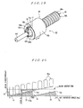
- FIGS. 21 to 23 An explanation will next be made to a fourth embodiment of the present invention with reference to FIGS. 21 to 23 .
- the fourth embodiment only one guide member 40 is provided in the configuration of the aforesaid first embodiment.
- the fourth embodiment as shown in FIGS. 21 and 22 , has the same structure as the aforesaid second embodiment, excepting that the locking piece 70 is omitted, a guide member 80 is provided in place of the guide groove 69c of the securing cover 69, and the guide projection 66e of the ball screw shaft 66 is formed into a column shape and provided in a width across flat 66g provided in the ball screw shaft 66
- the component elements corresponding to those shown in FIGS. 16 and 17 are denoted by the same reference numerals, and the detailed descriptions thereof will be omitted.
- the guide member 80 is rotatably disposed in a support hole 81 formed in an axial direction on an inner peripheral surface facing the ball screw shaft 66 of the securing cover 69.
- the guide member 80 is made e..g.. of steel, and is, as shown in FIGS. 22 and 23 , made of a column 80c having a cylindrical surface 80a and a flat surface 80b formed by cutting with a chord having a length shorter than the diameter and having a central angle ⁇ shorter than 180 degrees, when the column is viewed from a section, as shown in FIGS.. 22 and 23 .
- the column 80c has a cross-sectional shape similar to a semicircle or similar to a circle rather than the semicircle..
- a guide groove 82 is formed which extends in an axial direction, is deeper than a central axis of the cylindrical surface 80a, and is slightly wider than the external diameter of the guide projection 66e of the ball screw shaft 66.
- the guide projection 66e of the ball screw shaft 66 is engaged into the guide groove 82.
- the guide member 80 having the structure thus configured as above is formed by drawing a round bar using a die formed in the aforesaid cross-sectional shape to form a long shaped product, and then by cutting the product to a predetermined size.
- the support hole 81 formed in the securing cover 69 is, as shown in FIG. 23 , extended in an axial direction from the receiving portion 69a side to the other end side.
- the support hole 81 is formed into a cylindrical surface having an internal form substantially identical to an external form of the guide member 80, with reference to a section.. A position corresponding to the chord of the aforesaid guide member 80 of the cylindrical surface is exposed to the insertion hole 69b.
- the support hole 81 is set such that the central angle ⁇ is smaller than 180 degrees, and the length of the chord is shorter than the diameter.
- the guide member 80 is rotatably inserted into the support hole 81 of the securing cover 69 from the receiving portion 69a side, the guide groove 82 of the guide member 80 is disposed to face the insertion hole 69b, and the guide projection 66e of the ball screw shaft 66 is engaged into the guide groove 82. Subsequently, the method of assembling the above linear actuator 10 can be carried out in the same way as that of the second embodiment as described above, excepting that the guide member 80 is inserted through the securing cover 69 to be mounted on the housing 63 in which the ball screw mechanism 62 is installed.
- the guide member 80 is rotatably supported by the support hole 81 of the securing cover 69.
- the guide member 80 rotates in a clockwise direction, as shown in FIG. 24C , up to a state where the side surface of the guide projection 66e comes into a line contact state, following the right side surface of the guide groove 82, with the rotation of the guide projection 66e in a clockwise direction.
- the guide member 80 restricts the rotation of the guide projection 66e in a clockwise direction in the line contact state.
- the ball screw shaft 66 is subject not to rotate and the ball screw shaft 66 moves to the left in FIG.. 21 , by continuing to rotate the ball screw nut 6.5 in a clockwise direction in FIG. 22 .
- the ball screw shaft 66 moves in an axial direction under a condition where the guide projection 66e and the guide groove 82 maintain the line contact state shown in FIG. 24C . Therefore, the guide projection 66e is brought into the line contact with the guide groove 82, and prevents uneven wear in the guide projection 66e and the guide groove 82 even for long-term use..
- the guide projection 66e and guide groove 82 formed in the guide member 80 can be moved in an axial direction, while keeping the line contact state, thereby securely preventing the uneven wear.
- the guide member 80 is made of a separate member different from the securing cover 69 as a securing portion on which the guide member 80 is mounted, the guide member having a high wear resistance can be provided by forming the guide member 80 using the member having a high wear resistance.
- the material having a high wear resistance may be applied only to the guide member 80 to thereby eliminate the need for producing the entire securing cover 69 with a high wear resistant material, thereby reducing the manufacturing cost. Simultaneously, it is unlikely to incur enlargement of the guide projection 66e as there is no need to use the cam follower.
- the guide member 80 is made of a member having a high wear resistance
- surface treatment may be applied to the guide groove 82 slidingly in contact with the guide projection 66e, for improving the wear resistance and slidability. Even in this case, the surface treatment may be applied only to the guide member 80, thereby leading to cost reduction of the surface treatment.
- the central angle ⁇ of the chord of the support hole 81 supporting the guide member 80 is set smaller than 180 degrees, and the length of the chord is set shorter than the diameter of the support hole 81. In other words, a cross-sectional shape of the support hole 81 is formed into a shape over a semicircle. Therefore, during assembly to support the guide member 80 by the support hole 81, the guide member 80 is securely prevented from falling off to the ball screw shaft 66 side from the support hole 81.
- the guide member 80 may be formed into a stepped cylindrical structure which is comprised of the large-diameter portion 80d and the small-diameter portion 80e coupled thereto. Like this, where the guide member 80 is formed into the stepped cylindrical structure, the guide member 80 is produced by sinter process.
- the guide member 80 is formed into the stepped cylindrical structure as stated above, even for the support hole 81 formed in the securing cover 69, as shown in FIGS. 26 and 27 , it is preferable for the guide member 80 to be composed of: a large-diameter portion 81a to receive the large-diameter portion 81d of the guide member 80; a back side small-diameter portion 81b to receive the small-diameter portion 80e of the guide member 80; and a tapered portion 81c to couple between the large-diameter portion 81a and the small-diameter portion 81b.
- the securing cover 69 is formed e.g.
- a casting surface (cutting taper) is formed between the large-diameter portion 81a and the small-diameter portion 81b of the support hole 81.
- the guide member 80 may be provided at any circumferential position of the insertion hole 8b.
- an explanation has been made to the case where one set of the guide projection 66e and the guide member 80 are provided.
- the present invention is not limited thereto, and a set of the guide projection 66e and the guide member 80 may be provided in multiple locations.
- the guide projection 66e is formed into a cylinder.
- the present invention is not limited thereto, and it may be formed into any shape such as an elliptic cylinder and a prism, etc.
- an explanation has been made to the case where the guide projection 66e is formed into the width across flat 66g, it is not always the width across flat 66g.
- One flat surface is left unchanged which forms the guide projection 66e, so that the other flat surface may be formed into a cylindrical surface.
- the present invention is not limited thereto, and the spur gear 65c of the ball screw nut 65 and the bearing 64 may be arranged in an inverse relation. Namely, the bearing 64 may be disposed at a position of the spur gear 65c, the spur gear 65c may be disposed at a position of the bearing 64, the securing cover 69 may be used as a housing as the securing portion, and the housing 63 may be taken as the securing cover.
- the support hole 81 rotatably supporting the guide member 80 is formed in the housing as the securing portion,
- the guide projection 66e may be provided to the opposite side to the small-diameter shaft 66f of the large-diameter portion 66b of the ball screw shaft 66, and a support hole rotatably supporting the guide member 80 may be formed on an inner peripheral surface of the central opening 63a of the housing 63 as the securing portion.
- the linear actuator can be provided for simplifying the structure as well as preventing the occurrence of radial load on the ball screw mechanism.
Landscapes
- Engineering & Computer Science (AREA)
- General Engineering & Computer Science (AREA)
- Mechanical Engineering (AREA)
- Transmission Devices (AREA)
- Power Steering Mechanism (AREA)
Abstract
Description
- The present invention relates to a linear actuator equipped with a ball screw mechanism for converting a rotational motion transmitted to a rotational motion component into a linear motion..
- Typically, a linear actuator of this kind has a ball screw mechanism with a ball screw shaft and a ball screw nut screwed via a lot of balls into the ball screw shaft.. In this actuator, one of the ball screw shaft and the ball screw nut is defined as a rotational motion component for rotational driving, and the other of the ball screw shaft and the ball screw nut is defined as a linear motion component for linear motion. At this time, to assure a linear motion of the linear motion component, it needs to prevent the occurrence of simultaneous rotation with the rotational motion component.. A detent is generally attained by engaging a guide projection provided in the linear motion component into a guide groove formed in an axial direction in a securing portion.
- For example, it has been known an electric actuator including a ball screw mechanism composed of a nut supported via a rolling bearing mounted on housing movably and not movably in an axial direction; and a ball screw shaft arranged at the interior of the nut via a lot of balls and coaxially integrated with a driving shaft (see Patent Document 1). The electric actuator has a cylindrical sac hole having a flat surface facing each other the housing. A detent member is formed in a rectangular form having a flat surface to be engaged to the flat surface, and movably inserted into the sac hole in an axial direction. Further, a spiral rib is provided on an inner peripheral surface of the detent member. The rib is engaged into a screw groove to hold the screw shaft unrotatably with respect to the housing and movably in an axial direction.
- In such an electric actuator, a stopper is provided in the rotational motion component and the linear motion component to restrict stroke in an axial direction of the linear motion component in the rotational motion component and the linear motion component, in order to prevent come-off from a screwed state of the both.
To this end, there has been proposed a ball screw device in which a nut member and a bracket with a C-shaped section to which a rotational driving force is transmitted are integrally provided. A screw shaft securely disposed via balls is screwed with a nut member, a stopper pin is provided in the screw shaft and a cutout is formed in the bracket. When the nut member is rotated while rotating it in a shrinkage direction, the cutout abuts with the stopper pin at a predetermined position for forcibly stopping the nut member (see e.g. Patent Document 2). - Further, there has been proposed a ball screw-type feeder comprising: an inner member on an outer periphery of which a spiral groove raceway is formed; an outer member on an inner periphery of which a spiral groove is formed; a plurality of balls inserted between the two spiral grooves; and an annular cage in which plural pockets are formed to hold the balls, wherein a stopper is provided to engage at least on an end of the spiral groove raceway of the inner member or on an end of the spiral groove raceway of the outer member in a circumferential direction with respect to the cage to restrict movement of the cage in an axial direction (see e..g.. Patent Document 3).
- Furthermore, there has been proposed an electric actuator in which a flat surface is formed in a large-diameter portion of a ball screw nut. A cam follower is installed in a protruding manner toward the outside in an axial direction at substantially the center of the flat surface. An end of the cam follower is rotatably and slidably fitted in the cutout of the housing for suppressing rotation of the ball screw nut, with the rotation of the ball screw shaft (see e.g. Patent Document 4).
- Meanwhile, in the linear motion component, a detent mechanism is provided to suppress simultaneous rotation caused by torque due to the rotational motion component.
To this end, there has been proposed a ball screw including a screw shaft screwed via balls into a nut, wherein a detent member provided in the nut is engaged into a guide groove formed in the housing (see e.g. Patent Document. 5). Conversely, there has been also proposed an actuator in which a pin secured to the housing is engaged via a bush, serving as a friction reduction member, into a groove formed in a nut (see e.g. Patent Document 6). - Moreover, there has been proposed an electric actuator in which a flat surface is formed in a large-diameter portion of a ball screw nut.. A cam follower is installed in a protruding manner toward the outside in an axial direction at substantially the center of the flat surface, and an end of the cam follower is rotatably and slidably fitted in a cutout of housing to restrict rotation of the ball screw nut, with the rotation of the ball screw shaft (see e.g. Patent Document 7).
-
- Patent Document 1:
JP 2010-270887 A - Patent Document 2:
JP 2003-120782 A - Patent Document 3:
JP 2004-116561 A - Patent Document 4:
JP 2002-181156 A - Patent Document 5:
JP 2005-299726 A - Patent Document 6:
JP 2005-163922 A - Patent Document 7:
JP 2007-333046 A - In the prior art disclosed in Patent Document 1, since there is provided only a detent function not to rotate the screw shaft, serving as the linear motion component. The detent member would abut with the nut and stop at the stroke end, coming into a locked state accordingly.
In order to avoid coming into the locked state at the stroke end, in particular, it is necessary to provide a stopper function to restrict the stroke end for linear motion use, as described in the prior art ofPatent Documents 2 and 3. However, the prior art, disclosed inPatent Documents 2 and 3, has only the stopper function to restrict the stroke end of the linear motion component. In this situation, provision of a detent member is separately needed for the detent of the linear motion component. - That is, as shown conceptually in
FIGS. 28A and 28B , aball screw shaft 101 is screwed via balls (not shown) into aball screw nut 100 to be rotatably driven, alocking projection 102 proximate to theball screw nut 100 at the stroke end is provided in theball screw shaft 101, and alocking piece 103 to be locked with thelocking projection 102 is provided in theball screw nut 100. In theball screw shaft 101, aguide projection 104 is provided in a protruding manner at the opposite side of thelocking projection 102 with respect to theball screw nut 100. Theguide projection 104 is engaged into aguide groove 105 formed in a securing portion along theball screw shaft 101 for enabling the detent function. - In this way, separately providing the stopper function implemented by the
locking projection 102 and thelocking piece 103, and the detent function implemented by theguide projection 104 and theguide groove 105 remains unresolved, thus leading to a complex structure. Further, when theball screw shaft 101 reaches the stroke end and thelocking piece 103 of theball screw nut 100 is locked at thelocking projection 102, once large torque is input to theball screw nut 100 rotatably driven, the input torque is transmitted via thelocking piece 103 and thelocking projection 102 to theball screw shaft 101. The input torque is finally transmitted to the detent mechanism comprised of theguide projection 104 and theguide groove 105. At this moment, radial load is generated as a reaction force of the input torque between theball screw nut 100 and theball screw shaft 101. It is common that the ball screw mechanism is used in a state where the radial load is not applied. Thus, there is an unsolved problem that a situation where the radial load like this is generated is unfavorable. - Moreover, not to rotate the linear motion component, as disclosed in Patent Document 5, the detent member is engaged in an abutment portion of the cutout constituting a guide section of the housing. In this instance, the detent slidingly contacts with the abutment portion of the cutout, thereby generating large contact resistance between the detent member and the abutment portion and frictional wear.
- In order to reduce the contact resistance and the frictional wear, in the prior art disclosed in Patent Document 6, it takes steps to reduce the contact resistance between the groove and the projection for suppressing the frictional wear by using a friction reduction member. However, a predetermined gap is normally arranged between the groove and the projection in consideration of variability in assembling and processing performance. Therefore, even when the projection abuts with a groove side wall, the projection and the groove side wall comes into contact with each other at an angle forming a point contact (or line contact), giving rise to high contact pressure at a contact point. There is an unsolved problem that it leads to uneven abrasion and an increased rattle, even for long-term use.
- Further, in the prior art disclosed in Patent Document 7, since the cam follower is rotatably and slidably fitted in the groove, it may have some effect on the frictional wear. However, there is an unsolved problem that the provision of the cam follower increases the dimension of the projection and manufacturing cost.
The present invention is made focusing on the above-mentioned unresolved problems in the prior art. A first object of the present invention is to provide a linear actuator the structure of which can be simplified by adding a stopper function to a detent mechanism, and in addition, to prevent the occurrence of radial load.
A second object of the present invention is to provide a linear actuator in which uneven wear can be suppressed without the provision of a cam follower. - To accomplish the above first object, a first aspect of a linear actuator according to the present invention including a rotational motion component and a linear motion component, and comprising a ball screw mechanism to convert a rotational motion transmitted to the rotational motion component into a linear motion, wherein the ball screw mechanism has a guide projection projecting in a radial direction and provided in the linear motion component, and a guide groove engaged with the guide projection and disposed in a securing portion facing the linear motion component to guide the guide projection in an axial direction, and has a structure to make the linear motion component subject not to rotate, and wherein the guide projection has a projection projecting by a predetermined length from the guide groove, while engaging into the guide groove, at a stroke end of the linear motion component, and locks a locking portion provided in the rotational motion component to lock to the projection of the guide projection.
- A second aspect of the linear actuator according to the present invention, in the first aspect, the axial length of the guide projection may be set longer than a lead of the ball screw mechanism.
A third aspect of the linear actuator according to the present invention, in the first or second aspect, the locking portion may be integrally provided in the rotational motion component, may be formed before grooving of at least one of a ball screw groove and a circulating groove of the rotational motion component, and may be established as a reference for processing for at least one of the ball screw groove and the circulating groove. - To accomplish the above second object, a fourth aspect of the linear actuator according to the present invention includes a rotational motion component and a linear motion component, and comprising a ball screw mechanism to convert a rotational motion transmitted to the rotational motion component into a linear motion, wherein the ball screw mechanism has a guide projection projecting in a radial direction and provided in the linear motion component, and a guide groove engaged with the guide projection and disposed in a securing portion facing the linear motion component to guide the guide projection in an axial direction, and has a structure to make the linear motion component subject not to rotate, and wherein the guide groove is formed in a guide member having a cylindrical outer peripheral surface in the axial direction, and the guide member is rotatably held in a support hole formed in the axial direction at a position, facing the linear motion component, of the securing portion.
- A fifth aspect of the linear actuator according to the present invention, in the fourth aspect, the guide member may have a cross-sectional shape having an angle greater than a semicircle, and the support hole has a cross- sectional shape having an angle greater than a semicircle.
Further, a sixth aspect of the linear actuator according to the present invention, in the fifth aspect, the guide member may be formed of a cylindrical surface having an angle greater than a semicircle and a plane connecting an end of the cylindrical surface, and the guide groove is formed in the plane. - A seventh aspect of the linear actuator according to the present invention, in one of fourth to sixth aspects, the guide member may be formed by cutting a long member manufactured by drawing to a predetermined length.
Furthermore, an eighth aspect of the linear actuator according to the present invention, in one of fourth to sixth aspects, an external form of the guide member may be formed of a large-diameter portion and a small-diameter portion, and the support hole may have a large-diameter hole and a small-diameter hole respectively engaging to the large-diameter portion and the small-diameter portion of the guide member, and a tapered portion connecting the large-diameter hole to the small-diameter hole. - A ninth aspect of the linear actuator according to the present invention, in the eighth aspect, the guide member may be manufactured by a sintered product.
Moreover, a tenth aspect of the linear actuator according to the present invention, in one of fourth to ninth, a surface treatment may be applied to the guide member for improving a wear resistance and slidability. - An eleventh aspect of the linear actuator according to the present invention, in one of fourth to tenth aspects, the guide member may have on the cylindrical surface a concave groove to be engaged in a circumferential direction with a projecting rib formed on an inner peripheral surface of the support hole.
Moreover, a twelfth aspect of the linear actuator according to the present invention, in one of fourth to eleventh aspects, the guide projection may have a projection projecting by a predetermined length, while engaging in the guide groove at a stroke end of the linear motion component, and a locking portion provided in the rotational motion component is locked to the projection. - A thirteenth aspect of the linear actuator according to the present invention, in one of fourth to twelfth aspects, a pair of the guide projections may be provided in the linear motion component at a symmetry position with respect to a central axis of the linear motion component, a pair of the support holes are formed in the securing portion at a symmetry position with respect to a central axis of the linear motion component, a pair of the guide members are rotatably held in the pair of the support holes, respectively, and the pair of the guide projections are engaged into the guide grooves of the pair of the guide members, respectively.
- A fourteenth aspect of the linear actuator according to the present invention, in one of fourth to thirteenth aspects, the guide projection may be provided on an outer peripheral surface of a cylindrical body, and the cylindrical body is secured to a shaft provided in the linear motion component in a state where the cylindrical body is not movable in the circumferential direction and a position of the cylindrical body is adjusted in the axial direction.
Further, a fifteenth aspect of the linear actuator according to the present invention, in one of first to thirteenth aspects, the guide projection may be provided on an outer peripheral surface of the cylindrical body which has a spline hole formed on an inner peripheral surface, and the cylindrical body is secured to the linear motion component with the spline hole coupled with a spline axis provided in the linear motion component. - According to the present invention, the guide projection also serves as the stopper function exhibiting the detent function for the axial motion component of the ball screw mechanism, thereby exhibiting an advantageous effect of simplifying the structure and preventing the generation of the radial load on the ball screw mechanism.
Further, according to the present invention, the cylindrical guide member is provided with the detent groove to be engaged with the projection provided in the axial motion component of the ball screw mechanism, so that the guide member is rotatably supported by the securing portion. Thus, the guide groove to guide the projection follows a slant of the projection, thereby resulting in an advantageous effect of preventing the generation of uneven wear, even for long-term use. - Furthermore, since the guide member and a cross-sectional shape of a support hole supporting the guide member are set to have an angle larger than a semicircle, it is possible to prevent the guide member from falling down toward the axial motion component side.
Moreover, since the guide member and the securing portion are made of different members, it is possible to choose a material depending on its hardness necessary to guide the projection and to conduct necessary surface processing only for the guide member. Hence, cost reduction is achieved. -
-
FIG. 1 is a front view showing one embodiment of a linear actuator according to the present invention; -
FIG. 2 is a side view ofFIG. 1 ; -
FIG. 3 is a cross-sectional view taken along a line A-A ofFIG. 1 ; -
FIG.. 4 is a cross-sectional view taken along a line B-B ofFIG. 2 ; -
FIG. 5 is a cross-sectional view taken along a line C-C ofFIG. 4 ; -
FIG. 6 is a rear view of a housing; -
FIG. 7 is a cross-sectional view taken along a line D-D ofFIG. 6 ; -
FIG. 8 is a front view of a ball screw mechanism; -
FIG. 9 is a partially enlarged cross-sectional view taken along a line E-E ofFIG. 8 ; -
FIG. 10 is a view showing a ball nut, in whichFIG. 10A is a perspective view,FIG. 10B is a front view,FIG. 10C is a side view, andFIG. 10D is a cross-sectional view taken along a line F-F ofFIG. 10C ; -
FIG. 11 is a view showing a detent member, in whichFIG. 11A is a perspective view,FIG.. 11B is a front view, andFIG. 11C is a cross-sectional view; -
FIG.. 12 is a view showing a guide member, in whichFIG. 12A is a perspective view,FIG.. 12B is a front view, andFIG. 12C is a side view; -
FIG.. 13 is a front view showing an installation method of the guide member; -
FIG. 14 is an explanation diagram showing a positional relationship between a guide projection and a stopper of a first embodiment; -
FIG.. 15 is an explanation diagram used for an explanation of following of the guide member of a first embodiment; -
FIG. 16 is a cross-sectional view showing a second embodiment of the present invention; -
FIG. 17 is a perspective view showing a ball screw mechanism ofFIG. 16 ; -
FIG. 18 is an explanation diagram showing a positional relationship between a guide projection and a locking member of the second embodiment; -
FIG.. 19 is a perspective view showing a third embodiment of the present invention; -
FIG.. 20 is an explanation diagram showing a positional relationship between a guide projection and a locking member of the third embodiment; -
FIG. 21 is a cross-sectional view showing a fourth embodiment of the present invention; -
FIG. 22 is a cross-sectional view taken along a line G-G ofFIG. 21 ; -
FIG. 23 is a perspective view showing a guide member; -
FIG. 24 is an explanation drawing used for an explanation of following of the guide member; -
FIG. 25 is a perspective view showing a modification of a guide member in a fourth embodiment; -
FIG.. 26 is a cross-sectional view showing a support hole into which the guide member ofFIG. 25 is fitted; -
FIG. 27 is a cross-sectional view showing a state where the guide member is fitted into a support hole; and -
FIG. 28 is a schematic diagram showing prior art, in whichFIG. 28A is a front view, andFIG. 28B is a side view. - Hereinafter, a description will be made to embodiments of the present invention with reference to the accompanying drawings.
FIG. 1 is a front view showing one embodiment of a linear actuator according to the present invention;FIG. 2 is a side view; FIG. is a cross-sectional view taken along a line A-A ofFIG. 1 ; andFIG. 4 is a cross-sectional view taken along a line B-B ofFIG. 2 .
In the drawings,reference numeral 10 denotes a linear actuator with amain housing 11A and asub housing 11B both formed by die-cast molding using, for example, aluminium or aluminium alloy.. - The
main housing 11A has, as shown inFIGS. 3 and7 , amotor mounting portion 13 on which anelectric motor 12 is mounted at the front side, and a ball screwmechanism mounting portion 14 with the rear side for mounting aball screw mechanism 20 disposed in parallel with themotor mounting portion 13. Thesemotor mounting portions 13 and the ballscrew mounting portion 14 are provided so that their central axes are parallel.
Themotor mounting portion 13 has aflange mounting portion 13a to mount a mountingflange 12a of theelectric motor 12 provided at the front side; a large-diameter hole 13b into which a large-diameter portion 12b of theelectric motor 12 provided at the rear side of theflange mounting portion 13a is inserted; a small-diameter hole 13c into which a small-diameter portion 12c of theelectric motor 12 communicating with the rear side of the large-diameter hole 13b is inserted; and apinion receiving portion 13d communicating with the rear side of the small-diameter portion 13c. - The ball screw
mechanism mounting portion 14 has a ball screwmechanism receiving portion 14a provided at a position corresponding to the large-diameter hole 13c of themotor mounting portion 13 provided at the rear side; acylindrical body 14b extending forward in communication with the ball screwmechanism receiving portion 14a; and aseal receiving portion 14c communicating with the front end of thecylindrical body 14b. In the ball screwmechanism receiving portion 14a, as shown inFIGS. 6 and7 , anair hole 14d is formed to allow air to pass through thecylindrical body 14b. - The
sub housing 11B is, as shown inFIG. 3 , formed into a shape of covering thepinion receiving portion 13d and the ball screwmechanism receiving portion 14a provided at the rear side of themain housing 11A Thesub housing 11B is provided with apinion receiving portion 16 and a ball screwmechanism receiving portion 17 correspondingly to thepinion receiving portion 13d and the ball screwmechanism receiving portion 14a of themain housing 11A. In addition, abreather 18 is provided at the lower side. Here, a ballscrew receiving portion 17a is provided at the rear side of the ball screwmechanism receiving portion 17. Athrust needle bearing 17b is provided at a position at which thethrust needle bearing 17b comes into contact with an axial end face of theball screw nut 22, to be mentioned later, of the ballscrew receiving portion 17a. - The
electric motor 12 has, as shown inFIG. 3 , apinion gear 15 fitted to its end of anoutput shaft 12d. Then, theelectric motor 12 is mounted on themotor mounting portion 13. Theelectric motor 12 is mounted by inserting theelectric motor 12 into themotor mounting portion 13 from thepinion gear 15 side, and by mounting the mountingflange 12a on theflange mounting portion 13a, with thepinion gear 15 received in thepinion receiving portion 13d. - Meanwhile, the
ball screw mechanism 20 has aball screw nut 22, as a rotary motion component, rotatably supported by sealed rollingbearings screw receiving portions main housing 11A and the sub housing 14B. Theball screw mechanism 20 also has aball screw shaft 24, as a linear motion component to be screwed via a lot ofballs 23 into theball screw nut 22. - The ball screw
nut 22 is, as shown inFIG. 10 , configured of acylindrical member 25 on an inner peripheral surface of which aball screw groove 25a and aball circulating grooves 25b are formed. Herein, a ball circulating system of theball screw nut 22, as shown inFIG.. 10D , applies , for example, an S-shaped circulatinggroove 25b existing in each one turn is integrally formed with theball screw nut 22. The circulatinggrooves 25b is formed by cold forging and theball screw groove 25a is formed by machining. - Both axial end sides on an outer periphery surface of the
cylindrical member 25 are rotatably supported via the rollingbearings mechanism receiving portion 14a. Aninvolute spline shaft 25c is provided between inner rings of the rollingbearings cylindrical member 25. Further, astopper 25d, serving as a fan-shaped locking portion, when viewed from the front thereof, is integrally projected on an end face at the front side of thecylindrical member 25. - Herein, it is preferable that the
stopper 25d should be formed prior to grooving at least one of theball screw groove 25a and the circulatinggroove 25b of theball screw nut 22, serving as the rotary motion component, and the stopper should be taken as a reference for processing of at least one of theball screw groove 25a and the circulatinggroove 25b.
Further, thecylindrical member 25 has a drivengear 26 produced by injection molding synthetic resin materials containing e.g. glass fiber, and is spline coupled to theinvolute spline shaft 25c. The drivengear 26 is meshed with apinion gear 15 mounted on anoutput shaft 12d of theelectric motor 12. The drivengear 26 has on its inner peripheral surface aninvolute spline hole 26a to be meshed with theinvolute spline shaft 25c. - To mount the driven
gear 26 on thecylindrical member 25, theinvolute spline hole 26a of the drivengear 26 is firstly meshed with theinvolute spline shaft 25c of thecylindrical member 25. Next, the inner rings of the rollingbearings gear 26. This secures the drivengear 26 to thecylindrical member 25 not to be movable in axial and rotational directions. - The ball screw
shaft 24 is, as shown inFIGS. 3 and4 , mounted on thecylindrical body 14b provided in themain housing 11A and the ballscrew receiving portion 17a provided in thesub housing 11B. The ball screwshaft 24 is, as shown inFIG. 9 , composed of: aball screw 31 provided at the rear end side (lett side inFIG.. 9 ) from the center in an axial direction; aninvolute spline shaft 32 having a small diameter than that of theball screw 31 and linking to the front end side (right side inFIG. 9 ) of theball screw 31; and acoupling shaft 33 having a small diameter than that of theinvlote spline shaft 32 and linking to a front end of theinvolute spline shaft 32 and having a width across flat 33a is provided at its end.. - As shown in
FIGS. 3 ,4 , and9 , thedetent member 34 is spline engaged in theinvolute spline shaft 32 of theball screw shaft 24. Thedetent member 34, as shown inFIG. 11 , has on its inner peripheral surface acylindrical portion 35 in which aninvolute spline hole 35a is formed; and radially projectingguide projections cylindrical portion 35. Here, theguide projection 36 is set longer in the axial length than that of theguide projection 37, and is provided with aprojection 36a that abuts against thestopper 25d arranged in theball screw nut 22 at the axially rear end side in the stroke end to be mentioned later. - The
detent member 34 is, as shown in the enlarged view ofFIG. 9 , provided with a caulkedportion 32a by caulking the front end side of theinvolute spline shaft 32 from an axial direction at plural point, for example, at four points, up, down, left and right, in a state where theinvolute spline shaft 32 of theball screw shaft 24 is spline coupled to theinvolute spline hole 35a. Consequently, thedetent member 34 is fixed to theball screw shaft 24 by spline coupling not to be rotatable and by means of thecaulking portion 32a not to be movable in an axial direction of theball screw shaft 24. - Here, the axial length Lc of the
guide projection 36 is, as shown inFIG.. 14 , set longer than that a lead Lb of theball screw groove 25a. In other words, assuming that Ld is the locking length of theprojection 36a of theguide projection 36 and thestopper 25d, and Le is the locking length of aguide groove 40c necessary for detent, and Lf is a gap between an axial end of thestopper 25d and an end face at theball screw nut 22 side of theguide groove 40c, the axial length Lc of theguide projection 36 is set to:
where the locking length Ld is set shorter than the lead Lb (Ld < Lb). - The
guide projection 37, as shown inFIG. 11C , the projection length thereof projecting forward is set shorter than that of theguide projection 36. That is, theball screw nut 22 is rotated in a clockwise direction from the state where theprojection 36a of theguide projection 36 shown inFIG. 8 abuts against thestopper 25d and reaches the stroke end. When thestopper 25d reaches a position of overlapping theguide projection 37 in a circumferential direction, theguide projection 37 is set at an axial position where theguide projection 37 does not come into contact with thestopper 25d. - On the other hand, the inner peripheral surface of the
cylindrical body 14b of themain housing 11A is provided with, as shown inFIG. 5 ,support holes guide member 40. These support holes 41a and 41b are formed at symmetry positions through 180 degrees to be elongated in an axial direction. Each of thesesupport holes FIG.. 5 , formed into a shape which has in its cross-section a chord opened to an inner peripheral surface of thecylindrical body 14b so that its shape is larger than a semicircle, its length is shorter than the diameter, and its central angle θ is set smaller than 180 degrees, with an example of 140 degrees. - Thus, when the
guide member 40 is held, the support holes 41a and 41b prevent theguide member 40 from falling off therefrom, and from projecting to an inner peripheral surface of thecylindrical body 14b. Front ends of thesesupport holes seal receiving portion 14c.. In the support holes 41a and 41b, a projectingrib 41c inwardly projecting in a radial direction is provided at the front end side (left side inFIG.. 4 ) of thesesupport holes
Theguide member 40 is, as shown inFIGS. 4 ,5 , and12 , formed to have a cross-sectional shape substantially same as the aforementioned support holes 41a and 41b, and is made of , for example, steel. Namely, theguide member 40 is formed of a column produced by axially cutting the cylinder with a chord having the length shorter than the diameter and a central angle θ smaller than 180 degrees, when viewed from its section. - Accordingly, the
guide member 40 has acylindrical surface 40a and aflat surface 40b to have a cross-sectional shape similar to a semicircle or similar to a circle rather than the semicircle. At the center of theflat surface 40b, aguide groove 40c is formed which extends in an axial direction, is deeper than a central axis of an arc of the section, and has a width slightly greater than that of theguide projections detent member 34 of theball screw shaft 24. Into theguide groove 40c, theguide projection detent member 34 of theball screw shaft 24 is engaged. Also, on the outer peripheral surface of the front end side of theguide member 40, an engagegroove 40d is formed in a circumferential direction to engage with the projectingrib 41c of the support holes 41a and 41b. - The
guide member 40 having the above structure is formed by using a die formed into the aforementioned cross-sectional shape and drawing out a round bar to form a long shaped product, and by then cutting this shaped product to a predetermined size. After that, the engagegroove 40d is cut on the outer peripheral surface to provide theguide member 40.
Further, in themain housing 11A, as shown in FIGS. and 4, aseal 50 slidingly contact with an outer peripheral surface of thecoupling shaft 33 of theball screw shaft 24 is attached to theseal receiving portion 14c of the ball screwmechanism mounting portion 14, and theseal 50 is secured by asnap ring 51. - An explanation will next be made to an assembly method of the
linear actuator 10.
Firstly, theguide member 40 is respectively attached for holding it with the support holes 41a and 41b of themain housing 11A. To attach theguide member 40 in thesupport hole 41a (or 41b), firstly, as shown inFIG. 13A , theguide member 40 is inserted into thecylindrical body 14b, through theseal receiving portion 14c of themain housing 11A, with theguide groove 40c of theguide member 40 facing downward (a direction in which a depth direction of the support holes 41a and 41b is substantially parallel with theflat surface 40b). - Thereafter, the
guide member 40 is inserted into thesupport hole 41a (or 41b) with the engagegroove 40d of theguide member 40 facing the projectingrib 41c of thesupport hole 41a (or 41b), so that the projectingrib 41c is engaged into the engagegroove 40d. After that, by rotating theguide member 40 in a counterclockwise direction (or clockwise direction) inFIG.. 13A , theguide member 40 is held in thesupport hole 41a (or 41b) with theguide groove 40c being opened to the inner peripheral surface side of thecylindrical body 14b, as shown inFIG. 13B . At this time, the projectingrib 41c provided in thesupport hole 41a (or 41b) engages into the engagegroove 40d of theguide member 40, thereby preventing theguide member 40 from moving in an axial direction. - Meanwhile, the
ball screw mechanism 20 is separately assembled.. Theball screw mechanism 20 is assembled in the following procedure.. The drivengear 26 is firstly spline coupled at the axial center on an outer peripheral surface of thecylindrical member 25 of theball screw nut 22, the rollingbearings gear 26 is secured to inner rings of these rollingbearings
Before or after that, theball screw shaft 24 is screwed via theballs 23 into theball screw nut 22. Before or after that, theinvolute spline shaft 32 is caulked with thedetent member 34 spline coupled to theball screw shaft 24, so that thedetent member 34 is secured to theball screw shaft 24 not to be movable in axial and rotational directions. This produces theball screw mechanism 20 shown inFIG.. 9 . - Here, a mounting position of the
detent member 34 is set to a position where theprojection 36a of theguide projection 36 projects in an axial direction from theguide groove 40c, at the stroke end capable of preventing the balls located between theball screw nut 22 and theball screw shaft 24 from coming off outward, and thestopper 25d of theball screw nut 22 abuts with theprojection 36a.
Then, theball screw mechanism 20 is inserted into the ball screwmechanism receiving portion 14a of themain housing 11A from thecoupling shaft 33 side, and theguide projections detent member 34 are engaged into theguide groove 40c of theguide member 40 mounted on themain housing 11A. Finally, the drivengear 26 is received in the ball screwmechanism receiving portion 14a, while an outer ring of the rollingbearing 21a is being fitted to an inner peripheral surface of the ball screwmechanism receiving portion 14a. Thereby, the mounting of theball screw mechanism 20 on themain housing 11A is completed. - Afterwards, the
electric motor 12 is inserted into themotor mounting portion 13 of themain housing 11A from thepinion gear 15 side, and then thepinion gear 15 is meshed with the drivengear 26 of theball screw mechanism 20. Subsequently, the mountingflange 12a of theelectric motor 12 is secured to theflange mounting portion 13 by bolting.
Alternatively, theelectric motor 12 on themain housing 11A may be mounted before theball screw mechanism 20 is mounted on themain housing 11A. - In this way, when mounting of the
electric motor 12 and theball screw mechanism 20 on themain housing 11A are finished, thesub housing 11B is mounted on the rear side of themain housing 11A via a packing, not shown, to secure thesub housing 11B with securing means such as by bolting.. Aseal 50 is inserted into theseal receiving portion 14c of themain housing 11A and is prevented from falling off with thesnap ring 51, then assembly of thelinear actuator 50 is completed. - In this assembly completed state, as shown in
FIGS. 4 and5 , theguide projections detent member 34 are engaged into theguide groove 40c of theguide member 40. At this moment, theguide groove 40c and theguide projections FIG. 15A , selected so that the width of theguide groove 40c slightly gets larger than those of theguide projections - In this state, a situation is considered where the
electric motor 12 is rotary driven to transmit a rotational diving force from thepinion gear 15 to the drivengear 26, and theball screw nut 22 is rotated in a clockwise direction, for example, inFIG. 8 . In this instance, the rotational force of theball screw nut 22 is transmitted via aball 23 to theball screw shaft 24, and therefore theball screw shaft 24 is rotated in a clockwise direction which is the same direction as theball screw nut 22. At this time, theguide projections FIG.. 15B , also rotated in a clockwise direction, and ends of theguide projections guide groove 40c, coming into a line contact state, accordingly. - However, since the
guide member 40 is rotatably supported by the support holes 41a and 41b of themain housing 11A, when theguide projections guide projections guide groove 40c in a clockwise direction.
At this moment, a contact point of theguide projections guide member 40. Hence, with the rotation of theguide member 40 , as shown inFIG.. 15C , in a clockwise direction, theguide projection guide projection guide groove 40c. In this surface contact state, the rotation of theguide projections guide projections ball screw shaft 24 is restricted to exhibit a detent function.. - The ball screw
nut 22 continuously rotates in a clockwise direction inFIG. 8 , and then theball screw shaft 24 moves to the left as shown inFIGS. 3 and4 .. At this time, theball screw shaft 24 is moved in an axial direction, while keeping a surface contact state shown inFIG. 15C between theguide projections guide groove 40c of theguide member 40.
Thus, theguide projections guide groove 40c in the surface contact state ensures secure prevention of uneven wear in theguide projections guide groove 40c of theguide member 40, even for long-term use. - Similarly, when the
electric motor 12 is reversely rotated to transmit a rotational force in a counterclockwise direction to theball screw shaft 24 inFIG. 8 , the left side surfaces of theguide projections guide groove 40c of theguide member 40 in the surface contact state, and moves in an axial direction. This equally securely prevents uneven wear in theguide projections guide groove 40c of theguide member 40. - Then, when the
ball screw nut 22 is rotated in a clockwise direction from the stroke end, thestopper 25d reaches a position of theguide projection 37. As the projection length toward the rear end side of theguide projection 37 is set shorter than that of theguide projection 36, thestopper 25d never comes into contact with the rear end of theguide projection 37. Afterwards, when theball screw nut 22 is rotated one turn from the stroke end, as shown inFIG. 14 , an end of thestopper 25d of theball screw nut 22 is separated apart from the rear end of theguide projection 36, as is evident from a relationship of the locking length Ld < lead Lb. This avoids a circumstance where thestopper 25d abuts with an end face in a circumferential direction of theguide projection 36. - After that, when the
ball screw nut 22 continues to rotate and theball screw shaft 24 reaches a desired forward position, a forward movement of theball screw shaft 24 can be ceased by stopping the rotation of theelectric motor 12.
Thereafter, when theball screw shaft 24 reversely drives from a state where theball screw shaft 24 reaches a desired forward position at the forward side to rotate theball screw nut 22 in a counterclockwise direction shown inFIG.. 8 , theball screw shaft 24 retreats in an axial direction, as theguide projections ball screw shaft 24 are engaged into theguide groove 40c of theguide member 40 and come into a detent state. - When the
guide projection 36 of theball screw shaft 24 reaches a position (one turn short of the stroke end) facing thestopper 25d of theball screw nut 22, thestopper 25d never comes into contact with theguide projection 36, as is evident from a relationship of the locking length Ld < lead Lb, as described above. This allows a reverse rotation of theball screw nut 22. Therefore, the rear end of theguide projection 36 enters a trajectory of the end of thestopper 25d provided in theball screw nut 22. - Then, even when the
ball screw shaft 24 further retreats and thestopper 25d reaches a position of theguide projection 37, a reverse rotation of theball screw nut 22 is allowed without thestopper 25d abutting with thegroove projection 37, as the projection length of theguide projection 37 in a backward direction is shorter than that of theguide projection 36, as mentioned above. - After that, as shown in
FIG. 8 , thestopper 25d abuts with an end face in a circumferential direction of theprojection 36a of theguide projection 36. In this state, as shown inFIGS. 3 and4 , about half the axial length of theguide projection 36 is engaged into theguide groove 40c of theguide member 40. Hence, theball screw shaft 24 is in a detent state. Since thestopper 25d abuts with theprojection 36a of theguide projection 36 with the locking length Ld, thestopper 25d is locked at theguide projection 36 for restricting any further reverse rotation of theball screw nut 22. Then, theball screw shaft 24 reaches the rear side stroke end.. In the stroke end, theball screw shaft 24 stops its movement at a position where the rear end face of theball screw shaft 24 is proximate to the bottom surface of the ball screwmechanism receiving portion 17 of thesub housing 11B. - In this way, according to the above first embodiment, it is possible to move the
guide projections guide groove 40c formed in theguide member 40 in an axial direction, while keeping surface contact state therebetween. Hence, the uneven wear between theguide projections guide groove 40c of theguide member 40 can be prevented for certainty. Moreover, since theguide member 40 is constructed with a separate member different from themain housing 11A on which theguide member 40 is mounted, theguide member 40 may be produced using a member having a high wear resistance, thus providing a guide member having a high wear resistance. In this instance, the material having a high wear resistance has only to be applied to theguide member 40, and the entiremain housing 11A need not be made of a material having a high wear resistance. Thus, as this advantage attains low cost production as well as eliminates the need for use of a cam follower, the sizes of theguide projections - Moreover, in place of a case where the
guide member 40 is made of a member having a high wear resistance, the surface treatment may be applied to theguide groove 40c of theguide member 40 slidingly contact with the guide projections .36 and 37 for improving wear resistance and slidability. Even in this case, as the surface treatment has only to be applied to theguide member 40, it is possible to reduce the surface treatment cost. - Furthermore, central angles θ of the chords of the support holes 41a and 41b supporting the
guide member 40 are set to be smaller than 180 degrees, and the lengths of the chords thereof are set shorter than the diameters of the support holes 41a and 41b, that is cross-sectional shapes of the support holes 41a and 41b are set to be larger than a semicircle. On that account, in assembling theguide member 40 so that the support holes 41a and 41b hold theguide member 40, it is possible to prevent theguide member 40 from falling off from the support holes 41a and 41b to theball screw shaft 24 side.
Moreover, since the twoguide projections cylindrical member 25, it is made possible for theguide projections guide projections guide member 40, thereby reducing the possibility of the occurrence of wear. - Besides, according to the above first embodiment, when the
ball screw shaft 24 reaches the stroke end toward theball screw nut 22 side, thestopper 25d provided in theball screw nut 22 is locked at theguide projection 36 of thedetent member 34 having a detent function of theball screw shaft 24, to thereby exhibit a stopper function.
Accordingly, theguide projection 36 may have both the detent and stopper functions, which eliminates the necessity of providing the stopper function with a separate member. This simplifies the structure and also reduces the number of component parts, thereby reducing the production cost. - When the
ball screw shaft 24 reaches the stroke end, theguide projection 36 of theball screw shaft 24 is in an engaged state withguide groove 40c, and thestopper 25d provided in theball screw nut 22 abuts with theprojection 36a projecting from theguide groove 40c of theguide projection 36. On that account, when input torque transmitted to theball screw nut 22 is transmitted via thestopper 25d to theguide projection 36, the transmitted torque is received by theguide groove 40c through theguide projection 36, and further enters themain housing 11A from theguide groove 40c. This is because theguide projection 36 itself is engaged into theguide groove 40c. This securely prevents radial load acting on theball screw shaft 24 and theball screw nut 22. - Since the
air hole 14d communicating thecylindrical body 14b with thebreather 18 provided in thesub housing 11B is formed in the ball screwmechanism receiving portion 14a of themain housing 11A, it is possible to suppress air pressure fluctuations within thecylindrical body 14b from being generated, during advance or retreat of theball screw shaft 24, and to secure a smooth movement of theball screw shaft 24. - Further, the
detent member 34 is secured to theball screw shaft 24 by spline coupling thedetent member 34 to theball screw shaft 24, and by caulking the involute spline shaft. This enables adjustment of an axial position of thedetent member 34 with the aid of a spacer such as a washer, etc., inserted therebetween. This also enables adjustment of a phase, at a peak of spline, in which theguide projection 36 and thestopper 25d of theball screw nut 22 abut with each other. In other words, it is made possible to make fine adjustment of an axial end position at the stroke end of the ball screw shaft 24 (an example is that where a ball screw has a lead Ld and the number of teeth of spline is Z, the fitting with thedetent member 34 shifted by one tooth results in shifting of the axial end position by Lb/Z). - By applying sealed bearing as the rolling
bearings ball screw nut 22, it is possible to prevent interfusion of abrasion powders produced in the rollingbearings ball screw nut 22 and theball screw shaft 24.
Further, in the above first embodiment, since anoutput shaft 12d of theelectric motor 12 is set as the rear side, theball screw nut 22 is coupled via thepinion gear 15 and the drivengear 26 to theoutput shaft 12d, and thecoupling shaft 33 of theball screw shaft 24 to be screwed into theball screw nut 22 is projected forward, so that the axial length of thelinear actuator 10 can be shortened. - While in the above first embodiment, an explanation has been made to the case where the two
support holes main housing 11A to hold theguide member 40, and the twoguide projections detent member 34 of theball screw shaft 24. However, the present invention is not limited thereto, and one set or three or more sets of the guide members of the guide projections may be provided..
Whereas in the above first embodiment, an explanation has been made to the case where the fan-shapedstopper 25d is provided in theball screw nut 22, thestopper 25d may take an arbitrary shape. - Moreover, while in the above first embodiment, an explanation has been made to the case where the
guide projections cylindrical portion 35 to form thedetent member 34, and thedetent member 34 is spline coupled to theball screw shaft 24. However, the present invention is not limited thereto, and an outer periphery may be formed into a square tube and theguide projections detent member 34 may be configured such that a prism portion is provided at theball screw shaft 24 and theguide projections detent member 34 is adjusted by means of a rectangular washer, etc. so that a stroke end position of theball screw shaft 24 can be adjusted. - Further, while in the above first embodiment, an explanation has been made to the case where the
electric motor 12 and thecoupling shaft 33 of theball screw mechanism 20 are juxtaposed. However, the present invention is not limited thereto, and theelectric motor 12 may be juxtaposed with theball screw 31 of theball screw shaft 24.
Furthermore, whereas in the above first embodiment, an explanation has been made to the case where theelectric motor 12 and theball screw nut 22 of theball screw mechanism 20 are coupled by the gear type of power transmission mechanism. However, the present invention is not limited thereto, and they may be coupled by the use of a belt type of power transmission system utilizing a pulley and a timing belt, and another type of power transmission mechanism. - An explanation will then be made to a second embodiment of the present invention with reference to
FIGS. 16 to 18 .
In the second embodiment, theguide member 40 and the support holes 41a and 41b are eliminated in the above-mentioned first embodiment.
Namely, thelinear actuator 61 according to the second embodiment has, as shown inFIG. 16 , aball screw mechanism 62. Theball screw mechanism 62 is composed of: aball screw nut 65 rotatably supported by the bearing 64 in a large-diameter hole portion 63b communicating with acentral opening 63a formed as a securing portion in ahousing 63; aball screw shaft 66, as a linear motion component, to be screwed into theball screw nut 65; and a lot ofballs 67 interposed between theball screw nut 65 and theball screw shaft 66. - The ball screw
nut 65 is made of acylindrical member 65b on an inner peripheral surface on which aball screw groove 65a is formed. One end of an outer peripheral surface of thecylindrical member 65b is rotatably supported via abearing 64 by thehousing 63, and the other end thereof is provided with aspur gear 65c fitted thereon. Thespur gear 65c is meshed with aspur gear 65d coupled to a rotation axis of the electric motor as a rotation driving source, not shown. For this reason, theball screw nut 65 is rotary driven with the rotational force of the electric motor. - In the
ball screw nut 65, as shown inFIG. 17 , a column-shapedlocking piece 70 is provided as a locking portion in a projecting manner, at an outside position in an axial direction than theball screw groove 65a on anaxial end face 65e at thespur gear 65c side. When the lockingpiece 70 reaches the stroke end at the rear side of theball screw shaft 66, the lockingpiece 70 abuts with an end face in a circumferential direction of theguide projection 66e of theball screw shaft 66 to be mentioned later. Here, it is desirable that the lockingpiece 70 should be formed before theball screw groove 65a of theball screw nut 65, serving as a rotary motion component, is grooved, and thelocking piece 70 should be taken as a reference for processing for at least one of aball screw groove 25a and a circulatinggroove 25b. - The ball screw
shaft 66 is inserted into thecentral opening 63a formed in thehousing 63, and is composed of: a large-diameter portion 66b having an outer peripheral surface provided with aball screw groove 66a; aguide projection 66e outwardly projecting than the large-diameter portion 66b in a radial direction from asquare tube 66d fitted to aprism 66c provided at one end of the large-diameter portion 66b and from its one face; and a small-diameter shaft 66f connected to theprism 66c. - The axial length Lc of the
guide projection 66e is, as shown inFIG. 18 , set longer than that of the lead Lb of theball screw groove 66a.. That is, when Ld is the locking length between theguide projection 66e and thelocking piece 70, Le is the locking length between theguide projection 66e necessary for detent and theguide groove 69c to be mentioned later, and Lf is a gap between an end of the lockingpiece 70 and an end face of theball screw nut 65 side of theguide groove 69c, the axial length Lc of theguide projection 66e is set to:
where the locking length Ld is set shorter than that of the lead Lb (Ld < Lb). - At an end of the
housing 63 for receiving theball screw nut 65, a securingcover 69 as a securing portion is integrally secured by a securing member such as bolting. The securingcover 69 is formed with a receivingportion 69a for receiving theball screw nut 65, the securingcover 69 being produced by die-cast molding alminiuum, and almimiun alloy, etc. In the securingcover 69, aninsertion hole 69b having a diameter smaller than thecentral opening 63a of the housing 6.3 into which the small-diameter shaft 66f and the large-diameter portion 66b of theball screw shaft 66 are inserted and larger than the large-diameter portion 66b of theball screw shaft 66. On the inner peripheral surface side of theinsertion hole 69b, there is provided aguide groove 69c to guide theguide projection 66e of theball screw shaft 66. Theguide groove 69c opens on the receivingportion 69a side and astopper 69d abutting with theguide projection 66e is provided at the side opposite to the receivingportion 69a without opening. - An explanation will then be made to how to assemble the
linear actuator 61 according to the above second embodiment.
Firstly, theball screw shaft 66 is screwed via theball 67 into theball screw nut 65 to provide theball screw mechanism 62. The ball screwnut 65 of theball screw mechanism 62 is rotatably supported via thebearing 64 in the large-diameter portion 63b of thehousing 63 Thespur gear 65c fitted onto theball screw nut 65 is meshed with thespur gear 65d connected to a rotation shaft of the rotational driving source such as the electric motor, etc. - Secondly, the securing
cover 69 is attached to thehousing 63. At this time, the securingcover 69 is attached, while engaging theguide projection 66e of theball screw shaft 66 into theguide groove 69c of the securingcover 69. When the attachment is finished, the securingcover 69 is secured to thehousing 63 by the securing means such as bolting, etc, and the assembly of thelinear actuator 61 is completed
In the assembly completed state, as shown inFIGS, 16 and17 , suppose that the lockingpiece 70 of theball screw nut 65 abuts with an end face in a circumferential direction of theguide projection 66e of theball screw shaft 66, and is located at the stroke end at the rear side in an axial direction, In this state, theguide projection 66e is, as shown inFIG. 16 , engaged into theguide groove 69c of the securingcover 69 by about a half thereof in an axial direction. - From this state, in
FIG. 17 , theball screw nut 65 is rotated in a direction of an arrow A. Then, as shown inFIG. 18 , the lockingpiece 70 is spaced apart from theguide projection 66e by the rotation of theball screw nut 65. At the same time, since theguide projection 66e is engaged into theguide groove 69c of the securingcover 69 and theball screw shaft 66 is subject not to rotate, theball screw shaft 66 advances in an axial direction and theguide projection 66e also advances. - When the
ball screw nut 65 rotates one turn, as shown inFIG. 18 , an end of the lockingpiece 70 of theball screw nut 65 is separated from the rear end (right end face inFIG. 16 ) of theguide projection 66e, as is evident from a relationship of the locking length Ld < lead Lb. Thereby, the lockingpiece 70 will not abut with the end face in a circumferential direction of theguide projection 66e.
Thereafter, when theball screw nut 65 continues to rotate and an end face of the small-diameter shaft 66f side of theguide projection 66e of theball screw shaft 66 abuts with thestopper 69d of the securingcover 69, the advance of theball screw shaft 66 is stopped, and thescrew shaft 66 reaches the stroke end at the forward side Normally, the advance of theball screw shaft 66 is controlled, before theguide projection 66e of theball screw 65 abuts with thestopper 69d. - After that, when the
ball screw nut 65 is reversely rotated in a direction opposite to an arrow A, shown inFIG. 17 , from a state where theball screw shaft 66 is moving in a forward direction, theball screw shaft 66 is subject not to rotate and retreats in an axial direction in accordance with the reverse rotation of theball screw nut 65, as theguide projection 66e thereof is engaged into theguide groove 69c of the securingcover 69.
Then, when theguide projection 66e of theball screw shaft 66 reaches a position (one turn short of the stroke end) facing the lockingpiece 70 of theball screw nut 65, as mentioned above, a reverse rotation of theball screw nut 65 is allowed, as is evident from a relationship of the locking length Ld < lead Lb. - Thus, the
ball screw shaft 66 further retreats and the rear end of theguide projection 66e enters a trajectory at the end of the lockingpiece 70 provided in theball screw nut 65. Finally, as shown inFIG. 17 , the lockingpiece 70 abuts with an end face in a circumferential direction of theguide projection 66e. In this state, as shown inFig, 16 , theguide projection 66e engages into theguide groove 69c by about a half its axial length, and is in a detent state Since the lockingpiece 70 abuts with theguide projection 66e in the detent state with the locking length Ld, further reverse rotation of theball screw shaft 66 is restricted, and theball screw shaft 66 reaches the stroke end on the rear side (right side inFIG. 16 ). - In this way, according to the second embodiment, the stroke end toward the
ball screw nut 65 side of theball screw shaft 66 may exhibit the stopper function by abutting with the lockingpiece 70 provided in theball screw nut 65 to theguide projection 66e having the detent function of theball screw shaft 66.
Accordingly, theguide projection 66e may have both the detent and the stopper functions, which eliminates the need for providing the stopper function with a separate member This simplifies the structure as well as reduces the number of the parts, thereby reducing product cost. - Moreover, when the
ball screw shaft 66 reaches the stroke end, theguide projection 66e of theball screw shaft 66 is engaged into theguide groove 69c. The lockingpiece 70 provided in theball screw nut 65 is locked to the projection projecting from theguide groove 69c of theguide projection 66e. For this reason, when the input torque transmitted to theball screw nut 65 is transmitted via thelocking piece 70 to theguide projection 66e, the transmitted torque is received via theguide projection 66e in theguide groove 69c. This certainly prevents an action of radial load on theball screw shaft 66 and theball screw nut 65. - While in the above second embodiment, an explanation has been made to the case where the locking
piece 70 has a column shape. However, the present invention is not limited thereto, and the locking piece may be formed into a cylinder, a prism, or an arc prolonged in a circumferential direction, and therefore may take any shape. - An explanation will next be made to a third embodiment of the present invention with reference to
FIGS. 19 and 20 .
In the third embodiment, the locking member is formed of a spiral slope and a locking surface, by replacing the locking member with a locking piece.
In other words, in the second embodiment, as shown inFIG.. 19 , the third embodiment has the same structure as that of the second embodiment shown inFIG. 17 , excepting that the locking member provided in an end face of thespur gear 65c side of theball screw nut 65 is composed of: aspiral slope 72 provided so that the axial projection length gets gradually longer, as the locking member goes in a circumferential direction of a counterclockwise direction from astart edge 72a, with a predetermined width in a radial direction on the inner peripheral side from one point of a peripheral line in theend face 65e of thespur gear 65c side of theball screw nut 65; and a lockingsurface 73 locked to an end face in a circumferential direction of theguide projection 66e of theball screw shaft 66 which is provided by extending in an axial direction toward thestart edge 72a in an axial direction from thelongest projection 72b facing thestart edge 72a of thespiral slope 72. The component elements corresponding to those shown inFIG. 17 are denoted by the same reference numerals, and the detailed descriptions thereof will be omitted. - According to the third embodiment, as shown in
FIGS. 19 and 20 , theball screw nut 65 locked to an end face in a circumferential direction of theguide projection 66e of theball screw shaft 66 is rotated in a direction of an arrow A shown inFIG. 19 from a state where a locking surface 7.3 is located at the stroke end at the rear side. As shown inFIG. 20 , the lockingsurface 73 of thespiral slope 72 is spaced in a circumferential direction apart from theguide projection 66e in response to the rotation of theball screw nut 65. At the same time, since theguide projection 66e is engaged into theguide groove 69c of the securingcover 69 to make theball screw shaft 66 in a detent state, theball screw shaft 66 advances in an axial direction and theguide projection 66e also advances simultaneously therewith. - When the
ball screw nut 65 rotates one turn, as shown inFIG. 20 , the lockingsurface 73 of theball screw nut 65 is separated from the rear end of theguide projection 66e, and the lockingsurface 73 no longer abuts with an end face in a circumferential direction of theguide projection 66e.
Thereafter, theball screw nut 65 continues to rotate and stops the advance of theball screw shaft 66 at a desired position before an end face of the small-diameter shaft 66f side of theguide projection 66e of theball screw shaft 66 abuts with thestopper 69d of the securingcover 69 - When the
ball screw nut 65 is reversely rotated in a direction opposite to an arrow A shown inFIG. 19 from a state where theball screw shaft 66 is moving forward, theball screw shaft 66 is subject not to rotate and retreats in an axial direction with the reverse rotation of theball screw nut 65, as theguide projection 66e of theball screw shaft 66 is engaged into theguide groove 69c.
Then, when theguide projection 66e of theball screw shaft 66 reaches a position (one turn short of the stroke end) facing a lockingsurface 73 of theball screw nut 65, a reverse rotation of theball screw nut 65 is allowed as mentioned above, as is evident from a relationship of the locking length Ld < lead Lb. - On that account, the ball screw shaft 6 further retreats and the rear end of the
guide projection 66e enters a trajectory of thelongest projection 72b provided in theball screw nut 65. Finally, as shown inFIG 20 , the lockingsurface 73 abuts with an end face in a circumferential direction of theguide projection 66e.. In this state, as with the aforesaid second embodiment, about a half the axial length of theguide projection 66e engages into theguide groove 69c to be in the detent state. Since the lockingsurface 73 abuts with theguide projection 66e, a further reverse rotation of theball screw nut 65 is restricted, and theball screw shaft 66 reaches the stroke end at the rear side. - In this manner, even in the third embodiment, since the stroke end toward the
ball screw nut 65 side of theball screw shaft 66 causes the lockingsurface 73 of thespiral slope 72 provided in theball screw nut 65 to be locked at theguide projection 66e having a detent function of theball screw shaft 66, a stopper function can be exerted.
Accordingly, theguide projection 66e may have both the detent and stopper functions, which eliminates the need for providing the stopper function with a separate member This simplifies the structure as well as reduces the number of the parts, thereby reducing the product cost. - Further, when the
ball screw shaft 66 reaches the stroke end, theguide projection 66e of the ball screw shaft is engaged into theguide groove 69c. The lockingsurface 73 formed in theball screw nut 65 abuts with the projection projecting from theguide groove 69c of theguide projection 66e. Therefore, when the input torque transmitted to the ball screw nut 6.5 is transmitted via the locking surface 7.3 of thespiral slope 72 to theguide projection 66e, the transmitted torque is received by theguide groove 69c via theguide projection 66e. This certainly prevents an action of radial load on theball screw shaft 66 and theball screw nut 65. - According to the third embodiment, since the locking
surface 73 is formed on an end face of thespiral slope 72, it is possible to provide high stiffness against a force in a circumferential direction of the locking surface 7.3. Also, the lockingsurface 73 repeatedly abuts with an end face in a circumferential direction of theguide projection 66e, which suppresses a fatigue failure, thereby ensuring a long service life.
Incidentally, while in the above third embodiment, an explanation has been made to the case where thespiral slope 72 is configured such that the circumference of theball screw nut 65, i.e. thestart edge 72a matches thelongest projection 72b constituting the lockingsurface 73. However, the present invention is not limited thereto, and a slope of thespiral slope 12 may be steep and the slope length may be shorter than a circumference of a slope forming surface of theball screw nut 65. - Further, while in the above second and third embodiments, an explanation has been made to the case where the
prism 66c is provided in theball screw shaft 66 so that thesquare tube 66d of theguide projection 66e is fitted to theprism 66c. However, the present invention not limited thereto, and a flat surface formed of a width across flat or either one face of them may be provided in theball screw shaft 66, so that the guide projection may be fitted to the flat surface. In short, it has only to secure theguide projection 66e, extending in an axial direction to theball screw shaft 66, not to be rotatable. - An explanation will next be made to a fourth embodiment of the present invention with reference to
FIGS. 21 to 23 .
In the fourth embodiment, only oneguide member 40 is provided in the configuration of the aforesaid first embodiment.
Namely, in the fourth embodiment, as shown inFIGS. 21 and 22 , has the same structure as the aforesaid second embodiment, excepting that the lockingpiece 70 is omitted, aguide member 80 is provided in place of theguide groove 69c of the securingcover 69, and theguide projection 66e of theball screw shaft 66 is formed into a column shape and provided in a width across flat 66g provided in theball screw shaft 66 The component elements corresponding to those shown inFIGS. 16 and17 are denoted by the same reference numerals, and the detailed descriptions thereof will be omitted. - Herein, the
guide member 80 is rotatably disposed in asupport hole 81 formed in an axial direction on an inner peripheral surface facing theball screw shaft 66 of the securingcover 69. Theguide member 80 is made e..g.. of steel, and is, as shown inFIGS. 22 and23 , made of acolumn 80c having acylindrical surface 80a and aflat surface 80b formed by cutting with a chord having a length shorter than the diameter and having a central angle θ shorter than 180 degrees, when the column is viewed from a section, as shown inFIGS.. 22 and23 . Thecolumn 80c has a cross-sectional shape similar to a semicircle or similar to a circle rather than the semicircle.. At the center of theflat surface 80b, aguide groove 82 is formed which extends in an axial direction, is deeper than a central axis of thecylindrical surface 80a, and is slightly wider than the external diameter of theguide projection 66e of theball screw shaft 66. Theguide projection 66e of theball screw shaft 66 is engaged into theguide groove 82. Then, theguide member 80 having the structure thus configured as above is formed by drawing a round bar using a die formed in the aforesaid cross-sectional shape to form a long shaped product, and then by cutting the product to a predetermined size. - The
support hole 81 formed in the securingcover 69 is, as shown inFIG. 23 , extended in an axial direction from the receivingportion 69a side to the other end side. Thesupport hole 81 is formed into a cylindrical surface having an internal form substantially identical to an external form of theguide member 80, with reference to a section.. A position corresponding to the chord of theaforesaid guide member 80 of the cylindrical surface is exposed to theinsertion hole 69b. Here, thesupport hole 81 is set such that the central angle θ is smaller than 180 degrees, and the length of the chord is shorter than the diameter. When theguide member 80 is inserted into thesupport hole 81, theguide member 80 is prevented from falling off from thesupport hole 81 to project into theinsertion hole 69b. - The
guide member 80 is rotatably inserted into thesupport hole 81 of the securingcover 69 from the receivingportion 69a side, theguide groove 82 of theguide member 80 is disposed to face theinsertion hole 69b, and theguide projection 66e of theball screw shaft 66 is engaged into theguide groove 82.
Subsequently, the method of assembling the abovelinear actuator 10 can be carried out in the same way as that of the second embodiment as described above, excepting that theguide member 80 is inserted through the securingcover 69 to be mounted on thehousing 63 in which theball screw mechanism 62 is installed. - In the assembly completed state of the
linear actuator 10, as shown inFIGS. 21 and 22 , it comes to a state where theguide projection 66e of theball screw shaft 66 is engaged into theguide groove 82 of theguide member 80. On this occasion, theguide groove 82 and theguide projection 66e are, as shown inFIG. 24A , selected such that theguide groove 82 slightly wider than the diameter of theguide projection 66e. - In this state, when the
ball screw nut 65 is rotated in a clockwise direction inFIG. 24A by transmitting power via thespur gear 65d from a rotary driving source, not shown, to thespur gear 65c, the torque of the ball screw nut 6.5 is transmitted through theball 67 to theball screw shaft 66. Thereby, theball screw shaft 66 is about to rotate in a clockwise direction of the same direction as that of theball screw nut 65. At this moment, theguide projection 66e also rotates, as withFIG, 24B , in a clockwise direction, and falls into a state where the end of theguide projection 66e engages to the right side surface of theguide groove 82, coming into a point contact state. - However, the
guide member 80 is rotatably supported by thesupport hole 81 of the securingcover 69. Thus, when theguide projection 66e is rotated in a clockwise direction, the right side surface of theguide groove 82 is pressed in a clockwise direction by the end of theguide projection 66e. Since this contact point is located on the upper side than a central axis of theguide member 80, theguide member 80 rotates in a clockwise direction, as shown inFIG. 24C , up to a state where the side surface of theguide projection 66e comes into a line contact state, following the right side surface of theguide groove 82, with the rotation of theguide projection 66e in a clockwise direction. Theguide member 80 restricts the rotation of theguide projection 66e in a clockwise direction in the line contact state. - Hence, the
ball screw shaft 66 is subject not to rotate and theball screw shaft 66 moves to the left inFIG.. 21 , by continuing to rotate the ball screw nut 6.5 in a clockwise direction inFIG. 22 . At this time, theball screw shaft 66 moves in an axial direction under a condition where theguide projection 66e and theguide groove 82 maintain the line contact state shown inFIG. 24C . Therefore, theguide projection 66e is brought into the line contact with theguide groove 82, and prevents uneven wear in theguide projection 66e and theguide groove 82 even for long-term use.. - Similarly, when the counterclockwise torque is transmitted to the
ball screw shaft 66 inFIG. 22 , the left side surface of theguide projection 66e comes into contact with the left side surface of theguide groove 82 in a line contact state and moves in an axial direction. Likewise, this certainly prevents uneven wear in theguide projection 66e and theguide groove 82. - In this manner, according to the above fourth embodiment, the
guide projection 66e and guidegroove 82 formed in theguide member 80 can be moved in an axial direction, while keeping the line contact state, thereby securely preventing the uneven wear. Moreover, since theguide member 80 is made of a separate member different from the securingcover 69 as a securing portion on which theguide member 80 is mounted, the guide member having a high wear resistance can be provided by forming theguide member 80 using the member having a high wear resistance. In this instance, since the material having a high wear resistance may be applied only to theguide member 80 to thereby eliminate the need for producing the entire securingcover 69 with a high wear resistant material, thereby reducing the manufacturing cost. Simultaneously, it is unlikely to incur enlargement of theguide projection 66e as there is no need to use the cam follower. - Alternatively, instead of the case where the
guide member 80 is made of a member having a high wear resistance, surface treatment may be applied to theguide groove 82 slidingly in contact with theguide projection 66e, for improving the wear resistance and slidability. Even in this case, the surface treatment may be applied only to theguide member 80, thereby leading to cost reduction of the surface treatment.
Further, in the above fourth embodiment, the central angle θ of the chord of thesupport hole 81 supporting theguide member 80 is set smaller than 180 degrees, and the length of the chord is set shorter than the diameter of thesupport hole 81. In other words, a cross-sectional shape of thesupport hole 81 is formed into a shape over a semicircle. Therefore, during assembly to support theguide member 80 by thesupport hole 81, theguide member 80 is securely prevented from falling off to theball screw shaft 66 side from thesupport hole 81. - While in the above fourth embodiment, an explanation has been made to the case where the diameter of the cylindrical surface of the
guide member 80 is constant in an axial direction. However, the present invention is not limited thereto, and as shown inFIG. 25 , theguide member 80 may be formed into a stepped cylindrical structure which is comprised of the large-diameter portion 80d and the small-diameter portion 80e coupled thereto. Like this, where theguide member 80 is formed into the stepped cylindrical structure, theguide member 80 is produced by sinter process. - Where the
guide member 80 is formed into the stepped cylindrical structure as stated above, even for thesupport hole 81 formed in the securingcover 69, as shown inFIGS. 26 and 27 , it is preferable for theguide member 80 to be composed of: a large-diameter portion 81a to receive the large-diameter portion 81d of theguide member 80; a back side small-diameter portion 81b to receive the small-diameter portion 80e of theguide member 80; and a taperedportion 81c to couple between the large-diameter portion 81a and the small-diameter portion 81b. With this structure, when the securingcover 69 is formed e.g. by die-cast molding, a casting surface (cutting taper) is formed between the large-diameter portion 81a and the small-diameter portion 81b of thesupport hole 81. Thereby, manufacturing spots are made smaller only to the large-diameter portion 81a and the small-diameter portion 81b so that the manufacturing spots may be reduced as compared with a case where a simple cylindrical surface is adopted, thereby achieving the improvement in processing accuracy. - Further, whereas in the fourth embodiment, as shown in
FIG. 21 , an explanation has been made to the case where thesupport hole 81 is formed in the upper side of theinsertion hole 69b of the securingcover 69, theguide member 80 may be provided at any circumferential position of the insertion hole 8b.
Moreover, while in the above fourth embodiment, an explanation has been made to the case where one set of theguide projection 66e and theguide member 80 are provided. However, the present invention is not limited thereto, and a set of theguide projection 66e and theguide member 80 may be provided in multiple locations. - Moreover, while in the above fourth embodiment, an explanation has been made to the case where the
guide projection 66e is formed into a cylinder. However, the present invention is not limited thereto, and it may be formed into any shape such as an elliptic cylinder and a prism, etc. In addition, whereas an explanation has been made to the case where theguide projection 66e is formed into the width across flat 66g, it is not always the width across flat 66g. One flat surface is left unchanged which forms theguide projection 66e, so that the other flat surface may be formed into a cylindrical surface. - Further, while in the above fourth embodiment, an explanation has been made to the case where the
support hole 81 is formed in the securingcover 69. However, the present invention is not limited thereto, and thespur gear 65c of theball screw nut 65 and thebearing 64 may be arranged in an inverse relation. Namely, the bearing 64 may be disposed at a position of thespur gear 65c, thespur gear 65c may be disposed at a position of thebearing 64, the securingcover 69 may be used as a housing as the securing portion, and thehousing 63 may be taken as the securing cover. On this occasion, thesupport hole 81 rotatably supporting theguide member 80 is formed in the housing as the securing portion, - Furthermore, in the structure shown in
FIG. 21 , theguide projection 66e may be provided to the opposite side to the small-diameter shaft 66f of the large-diameter portion 66b of theball screw shaft 66, and a support hole rotatably supporting theguide member 80 may be formed on an inner peripheral surface of thecentral opening 63a of thehousing 63 as the securing portion. - While in the above first to fourth embodiments, explanations have been made to the case where the
ball screw nuts ball screw shafts ball screw shafts ball screw nuts
While in the above first to fourth embodiments, explanations have been made to the case where steel is adopted for the material of theguide members - Since the guide projection may at least have a stopper function exhibiting the detent function of the linear motion component of the ball screw mechanism, the linear actuator can be provided for simplifying the structure as well as preventing the occurrence of radial load on the ball screw mechanism..
-
- 10:
- linear actuator
- 11A:
- main housing
- 11B:
- sub housing
- 12:
- electric motor
- 13:
- motor mounting portion
- 14:
- ball screw mechanism mounting portion
- 15:
- pinion gear
- 16:
- pinion receiving portion
- 17:
- ball screw mechanism receiving portion
- 18:
- breather
- 20:
- ball screw mechanism
- 21a, 21b:
- rolling bearing
- 22:
- ball screw nut
- 23:
- ball
- 24:
- ball screw shaft
- 25a:
- ball screw groove
- 25b:
- circulating groove
- 25c:
- involute spline shaft
- 25d:
- stopper
- 26:
- driven gear
- 26a:
- involute spline hole
- 31:
- ball screw
- 32:
- involute spline shaft
- 33:
- coupling shaft
- 34:
- detent member
- 35:
- cylindrical portion
- 35a:
- involute spline hole
- 36:
- guide projection
- 36a:
- projection
- 37:
- guide projection
- 40:
- guide member
- 40a:
- cylindrical surface
- 40b:
- flat surface
- 40c:
- guide groove
- 40d:
- engage groove
- 41a, 41b:
- support hole
- 41c:
- projecting rib
- 50:
- seal
- 61:
- linear actuator
- 62:
- ball screw mechanism
- 63:
- housing
- 64:
- bearing
- 65:
- ball screw nut
- 66:
- ball screw shaft
- 66a:
- ball screw groove
- 66b:
- large-diameter portion
- 66c:
- prism
- 66d:
- square tube
- 66e:
- guide projection
- 66f:
- small-diameter shaft
- 66g:
- width across flat
- 67:
- ball
- 69:
- securing cover
- 70:
- locking piece
- 71:
- support hole
- 72:
- spiral slope
- 73:
- locking surface
- 80:
- guide member
- 80a:
- cylindrical surface
- 80b:
- flat surface
- 80c:
- column
- 80d:
- large-diameter portion
- 80e:
- small-diameter portion
- 81:
- support hole
- 81a:
- large-diameter portion
- 81b:
- small-diameter portion
- 81c:
- tapered portion
- 82:
- guide groove
Claims (15)
- A linear actuator including a rotational motion component and a linear motion component, and comprising a ball screw mechanism to convert a rotational motion transmitted to the rotational motion component into a linear motion,
wherein the ball screw mechanism has a guide projection projecting in a radial direction and provided in the linear motion component, and a guide groove engaged with the guide projection and disposed in a securing portion facing the linear motion component to guide the guide projection in an axial direction, and has a structure to make the linear motion component subject not to rotate, and
wherein the guide projection has a projection projecting by a predetermined length from the guide groove, while engaging into the guide groove, at a stroke end of the linear motion component, and abuts a abutting portion provided in the rotational motion component with the projection of the guide projection. - The linear actuator according to claim 1, wherein the axial length of the guide projection is set longer than a lead of the ball screw mechanism.
- The linear actuator according to claim 1 or claim 2, wherein the locking portion is integrally provided in the rotational motion component, is formed before grooving of at least one of a ball screw groove and a circulating groove of the rotational motion component, and established as a reference for processing for at least one of the ball screw groove and the circulating groove.
- A linear actuator including a rotational motion component and a linear motion component, and comprising a ball screw mechanism to convert a rotational motion transmitted to the rotational motion component into a linear motion,
wherein the ball screw mechanism has a guide projection projecting in a radial direction and provided in the linear motion component, and a guide groove engaged with the guide projection and disposed in a securing portion facing the linear motion component to guide the guide projection in an axial direction, and has a structure to make the linear motion component subject not to rotate, and
wherein the guide groove is formed in a guide member having a cylindrical outer peripheral surface in the axial direction, and the guide member is rotatably held in a support hole formed in the axial direction at a position, facing the linear motion component, of the securing portion. - The linear actuator according to claim 4, wherein the guide member has a cross-sectional shape having an angle greater than a semicircle, and the support hole has a cross-sectional shape having an angle greater than a semicircle.
- The linear actuator according to claim 5, wherein the guide member is formed of a cylindrical surface having an angle greater than a semicircle and a plane connecting an end of the cylindrical surface, and the guide groove is formed in the plane.
- The linear actuator according to one of claim 4 to claim 6, wherein the guide member is formed by cutting a long member manufactured by drawing to a predetermined length.
- The linear actuator according to one of claim 4 to claim 6, wherein an external form of the guide member is formed of a large-diameter portion and a small-diameter portion, and
wherein the support hole has a large-diameter hole and a small-diameter hole respectively engaging to the large-diameter portion and the small-diameter portion of the guide member, and a tapered portion connecting the large-diameter hole to the small-diameter hole. - The linear actuator according to claim 8, wherein the guide member is manufactured by a sintered product.
- The linear actuator according to one of claim to claim 4 to claim 9, wherein a surface treatment is applied to the guide member for improving a wear resistance and slidability.
- The linear actuator according to one of claim to claim 4 to claim 10, wherein the guide member has on the cylindrical surface a concave groove to be engaged in a circumferential direction with a projecting rib formed on an inner peripheral surface of the support hole.
- The linear actuator according to one of claim to claim 4 to claim 11, wherein the guide projection has a projection projecting by a predetermined length, while engaging in the guide groove at a stroke end of the linear motion component, and a locking portion provided in the rotational motion component is locked to the projection.
- The linear actuator according to one of claim to claim 4 to claim 12, wherein a pair of the guide projections are provided in the linear motion component at a symmetry position with respect to a central axis of the linear motion component, a pair of the support holes are formed in the securing portion at a symmetry position with respect to a central axis of the linear motion component, a pair of the guide members are rotatably held in the pair of the support holes, respectively, and the pair of the guide projections are engaged into the guide grooves of the pair of the guide members, respectively.
- The linear actuator according to one of claim to claim 1 to claim 13, wherein the guide projection is provided on an outer peripheral surface of a cylindrical body, and the cylindrical body is secured to a shaft provided in the linear motion component in a state where the cylindrical body is not movable in the circumferential direction and a position of the cylindrical body is adjusted in the axial direction.
- The linear actuator according to one of claim to claim 1 to claim 13, wherein the guide projection is provided on an outer peripheral surface of the cylindrical body which has a spline hole formed on an inner peripheral surface, and the cylindrical body is secured to the linear motion component with the spline hole coupled with a spline axis provided in the linear motion component.
Applications Claiming Priority (4)
| Application Number | Priority Date | Filing Date | Title |
|---|---|---|---|
| JP2010101448 | 2010-04-26 | ||
| JP2010108367 | 2010-05-10 | ||
| JP2011091091 | 2011-04-15 | ||
| PCT/JP2011/002453 WO2011135849A1 (en) | 2010-04-26 | 2011-04-26 | Linear actuator |
Publications (3)
| Publication Number | Publication Date |
|---|---|
| EP2520829A1 true EP2520829A1 (en) | 2012-11-07 |
| EP2520829A4 EP2520829A4 (en) | 2013-10-23 |
| EP2520829B1 EP2520829B1 (en) | 2016-03-02 |
Family
ID=44861171
Family Applications (1)
| Application Number | Title | Priority Date | Filing Date |
|---|---|---|---|
| EP11774635.4A Active EP2520829B1 (en) | 2010-04-26 | 2011-04-26 | Linear actuator |
Country Status (5)
| Country | Link |
|---|---|
| US (1) | US8656798B2 (en) |
| EP (1) | EP2520829B1 (en) |
| JP (3) | JP5293887B2 (en) |
| CN (1) | CN102947620B (en) |
| WO (1) | WO2011135849A1 (en) |
Cited By (3)
| Publication number | Priority date | Publication date | Assignee | Title |
|---|---|---|---|---|
| EP3006778A4 (en) * | 2013-05-29 | 2017-05-31 | NTN Corporation | Electric linear actuator |
| EP3018385A4 (en) * | 2013-09-19 | 2017-06-07 | NSK Ltd. | Ball screw |
| IT201700004014A1 (en) * | 2017-01-16 | 2018-07-16 | Ognibene Power Spa | STEERING SYSTEM |
Families Citing this family (37)
| Publication number | Priority date | Publication date | Assignee | Title |
|---|---|---|---|---|
| US20130068053A1 (en) * | 2011-09-20 | 2013-03-21 | Goodrich Corporation | Actuator system and method |
| JP5897874B2 (en) * | 2011-11-11 | 2016-04-06 | Ntn株式会社 | Electric linear actuator |
| JP5918510B2 (en) * | 2011-11-16 | 2016-05-18 | Ntn株式会社 | Electric linear actuator |
| JP5914031B2 (en) * | 2012-02-17 | 2016-05-11 | Ntn株式会社 | Electric linear actuator |
| JP5877763B2 (en) * | 2012-06-21 | 2016-03-08 | Ntn株式会社 | Electric linear actuator |
| JP6074192B2 (en) * | 2012-08-17 | 2017-02-01 | Ntn株式会社 | Electric linear actuator |
| JP5855547B2 (en) * | 2012-08-27 | 2016-02-09 | Ntn株式会社 | Electric linear actuator |
| JP6111038B2 (en) * | 2012-10-12 | 2017-04-05 | Ntn株式会社 | Electric linear actuator |
| JP6091149B2 (en) * | 2012-10-12 | 2017-03-08 | Ntn株式会社 | Electric linear actuator |
| JP6091148B2 (en) * | 2012-10-12 | 2017-03-08 | Ntn株式会社 | Electric linear actuator |
| US9182022B2 (en) * | 2012-10-17 | 2015-11-10 | Honeywell International Inc. | Ball screw actuator including a stop with an integral guide |
| JP6111042B2 (en) * | 2012-10-30 | 2017-04-05 | Ntn株式会社 | Electric linear actuator |
| JP6111078B2 (en) | 2013-01-18 | 2017-04-05 | Ntn株式会社 | Electric linear actuator |
| US9303743B2 (en) * | 2013-12-16 | 2016-04-05 | Honeywell International Inc. | Ball screw actuator including an axial soft stop |
| CN104879463A (en) * | 2015-05-05 | 2015-09-02 | 四川大学 | Gear enabling screw rod to move axially and movement mechanism |
| JP6779645B2 (en) * | 2016-03-30 | 2020-11-04 | Ntn株式会社 | Electric actuator |
| US10272891B2 (en) | 2016-07-28 | 2019-04-30 | Kelsey-Hayes Company | Compliant torque coupler for a dual acting plunger assembly of a vehicle brake system |
| CN107795653B (en) * | 2016-08-30 | 2020-03-17 | 上银科技股份有限公司 | Linear drive system for installation in a prosthetic limb |
| DE102016216496A1 (en) * | 2016-09-01 | 2018-03-01 | Schaeffler Technologies AG & Co. KG | screw |
| JP6704827B2 (en) * | 2016-09-30 | 2020-06-03 | 日本電産サンキョー株式会社 | Linear drive |
| JP2018078698A (en) * | 2016-11-08 | 2018-05-17 | Ntn株式会社 | Direct acting type electric actuator |
| FR3063527B1 (en) * | 2017-03-06 | 2019-04-05 | Safran Electronics & Defense | INTEGRATED LOCKING VERIN |
| JP6513758B2 (en) * | 2017-09-26 | 2019-05-15 | 株式会社栗本鐵工所 | Valve opening adjustment mechanism |
| JP7000848B2 (en) | 2017-12-26 | 2022-01-19 | 日本精工株式会社 | Linear actuator |
| JP2019113167A (en) * | 2017-12-26 | 2019-07-11 | 日本精工株式会社 | Linear motion actuator and assembling method of linear motion actuator |
| WO2019194143A1 (en) * | 2018-04-06 | 2019-10-10 | パナソニックIpマネジメント株式会社 | Linear motion mechanism and electric actuator provided with same |
| JP7196420B2 (en) | 2018-05-22 | 2022-12-27 | 日本精工株式会社 | linear actuator |
| KR102575396B1 (en) * | 2018-06-21 | 2023-09-07 | 현대자동차주식회사 | Method and apparatus for limitted steering angle in steer-by-wire system |
| IT201800007766A1 (en) * | 2018-08-02 | 2020-02-02 | Magneti Marelli Spa | FLEXIBLE LINEAR ELECTRIC ACTUATOR FOR AUTOMOTIVE APPLICATIONS |
| EP3608557B1 (en) * | 2018-08-09 | 2023-08-02 | SFS Group International AG | Ball screw |
| DE102019104125A1 (en) * | 2019-02-19 | 2020-08-20 | Knorr-Bremse Systeme für Nutzfahrzeuge GmbH | Ball screw drive with anti-twist device |
| KR102620009B1 (en) * | 2019-03-19 | 2024-01-02 | 현대모비스 주식회사 | Electric booster |
| DE102020202843A1 (en) * | 2019-04-25 | 2020-10-29 | Robert Bosch Gesellschaft mit beschränkter Haftung | Electromechanical brake pressure generator with a screw drive arrangement |
| KR20220039749A (en) * | 2019-07-31 | 2022-03-29 | 엔티엔 가부시키가이샤 | electric actuator |
| US11204082B2 (en) * | 2020-01-17 | 2021-12-21 | Steering Solutions Ip Holding Corporation | Steer by wire rotational travel stop |
| WO2022224903A1 (en) * | 2021-04-21 | 2022-10-27 | 日本精工株式会社 | Ball screw device |
| JP7272514B1 (en) | 2021-07-01 | 2023-05-12 | 日本精工株式会社 | ball screw device |
Citations (5)
| Publication number | Priority date | Publication date | Assignee | Title |
|---|---|---|---|---|
| FR2535001A1 (en) * | 1982-10-21 | 1984-04-27 | Sueddeutsche Kuehler Behr | Air flap drive for vehicle air conditioning equipment |
| US5784922A (en) * | 1994-08-06 | 1998-07-28 | Kabushiki Kaisha Toyoda Jidoshokki Seisakusho | Motor for converting rotation of a shaft to linear movement |
| EP0933565A2 (en) * | 1998-01-30 | 1999-08-04 | Mitsubishi Denki Kabushiki Kaisha | Actuator for operating speed change controlling valve of an automatic speed changer |
| US6101889A (en) * | 1998-01-20 | 2000-08-15 | Thomson Saginaw Ball Screw Company, Llc | Ball screw and nut linear actuator assemblies and methods of constructing and operating them |
| US6116106A (en) * | 1997-01-28 | 2000-09-12 | Mitsubishi Denki Kabushiki Kaisha | Rotation-reciprocation converting rotor |
Family Cites Families (39)
| Publication number | Priority date | Publication date | Assignee | Title |
|---|---|---|---|---|
| US808273A (en) * | 1904-05-11 | 1905-12-26 | Sprague Electric Co | Hoist and similar apparatus. |
| US2356861A (en) * | 1943-06-02 | 1944-08-29 | Baldwin Locomotive Works | Mechanical limit stop |
| US2417434A (en) * | 1945-02-13 | 1947-03-18 | Bell Telephone Labor Inc | Mechanical stop device |
| US2504408A (en) * | 1945-03-29 | 1950-04-18 | Cons Car Heating Co Inc | Electric door operator with auxiliary operating means |
| US2479019A (en) * | 1947-12-03 | 1949-08-16 | Bendix Aviat Corp | Actuator nut |
| US2590251A (en) * | 1948-09-29 | 1952-03-25 | Vaino A Hoover | Mechanical actuator |
| US3029660A (en) * | 1959-11-05 | 1962-04-17 | Beaver Prec Products Inc | Ball screw with stop means |
| US3334948A (en) * | 1964-01-07 | 1967-08-08 | Atlas Copco Ab | Drill steel guides |
| SE439968B (en) * | 1982-10-19 | 1985-07-08 | Ulf Kenneth Folke Fasth | STELLDON |
| FR2567979B1 (en) * | 1984-07-18 | 1986-12-19 | Somfy | LINEAR ACTUATOR WITH SCREW NUT SYSTEM |
| US4783708A (en) * | 1985-03-11 | 1988-11-08 | Mitsubishi Denki Kabushiki Kaisha | Guide mechanism incorporating a cylindrical bearing |
| US4712441A (en) * | 1985-05-13 | 1987-12-15 | Brunswick Valve & Control, Inc. | Position controlled linear actuator |
| US4858481A (en) * | 1985-05-13 | 1989-08-22 | Brunswick Valve & Control, Inc. | Position controlled linear actuator |
| NO156585C (en) * | 1985-06-21 | 1987-10-21 | Thune Eureka As | DEVICE FOR REGULATABLE ROLLING STOCK FOR SIDE CONTROL OF CURRENT RAILWAYS. |
| US4712927A (en) * | 1987-03-16 | 1987-12-15 | Robert Arrendiell | Nested plastic extension slide |
| US4867295A (en) * | 1988-01-25 | 1989-09-19 | Sundstrand Corporation | Shock absorbing overtravel stop |
| JPH0233171U (en) | 1988-08-29 | 1990-03-01 | ||
| US5329825A (en) * | 1992-11-25 | 1994-07-19 | Eastman Kodak Company | Precision moving stage |
| US5461935A (en) * | 1994-01-18 | 1995-10-31 | Emerson Electric Co. | Slip clutch linear actuator |
| JP3510669B2 (en) * | 1994-06-22 | 2004-03-29 | Smc株式会社 | Linear guide and manufacturing method thereof |
| JP3510672B2 (en) * | 1994-07-01 | 2004-03-29 | Smc株式会社 | Linear guide and manufacturing method thereof |
| JPH0851755A (en) * | 1994-08-06 | 1996-02-20 | Toyota Autom Loom Works Ltd | Antiskid mechanism for screw shaft of direct drive conversion motor |
| JPH0849782A (en) * | 1994-08-06 | 1996-02-20 | Toyota Autom Loom Works Ltd | Screw shaft turning-stop mechanism for linear-motion converter motor |
| FR2809464B1 (en) * | 2000-05-26 | 2002-10-11 | Commissariat Energie Atomique | SCREW TRANSMISSION, NUT AND CABLE ATTACHED TO SCREW |
| DE20013363U1 (en) * | 2000-08-03 | 2000-12-21 | Igus Gmbh | Floating bearing |
| JP4096510B2 (en) | 2000-12-14 | 2008-06-04 | 株式会社ジェイテクト | Ball screw type feeder and continuously variable transmission |
| JP3919070B2 (en) | 2001-10-15 | 2007-05-23 | 株式会社ジェイテクト | Ball screw device |
| JP2004116561A (en) | 2002-09-24 | 2004-04-15 | Nsk Ltd | Ball screw |
| US6935097B2 (en) * | 2003-04-17 | 2005-08-30 | Honeywell International, Inc. | Lock assembly that inhibits thrust reverser movement at or near the stowed position |
| JP4619646B2 (en) * | 2003-11-19 | 2011-01-26 | 株式会社アイエイアイ | Actuator |
| JP2005163922A (en) | 2003-12-03 | 2005-06-23 | Nsk Ltd | Actuator |
| JP4496827B2 (en) | 2004-04-07 | 2010-07-07 | 日本精工株式会社 | Ball screw mechanism |
| DE202004016094U1 (en) * | 2004-10-15 | 2006-02-23 | Igus Gmbh | Slide bearing and linear guide |
| DE102006006925A1 (en) * | 2006-02-14 | 2007-08-16 | Robert Bosch Gmbh | Spindle drive, in particular for adjusting a movable part in the motor vehicle |
| JP2007333046A (en) | 2006-06-14 | 2007-12-27 | Ntn Corp | Electric actuator |
| GB0706248D0 (en) * | 2007-03-30 | 2007-05-09 | Goodrich Actuation Systems Ltd | Stop device |
| JP5106145B2 (en) * | 2008-01-22 | 2012-12-26 | オリエンタルモーター株式会社 | Cylinder type actuator |
| JP2010031965A (en) * | 2008-07-29 | 2010-02-12 | Canon Electronics Inc | Rotation-linear motion converting mechanism, and injection device using the mechanism and injection molding machine using the device |
| JP2010270887A (en) | 2009-05-25 | 2010-12-02 | Ntn Corp | Electric actuator |
-
2011
- 2011-04-26 WO PCT/JP2011/002453 patent/WO2011135849A1/en active Application Filing
- 2011-04-26 US US13/516,454 patent/US8656798B2/en active Active
- 2011-04-26 JP JP2012512668A patent/JP5293887B2/en active Active
- 2011-04-26 CN CN201180004886.1A patent/CN102947620B/en active Active
- 2011-04-26 EP EP11774635.4A patent/EP2520829B1/en active Active
-
2013
- 2013-03-08 JP JP2013046452A patent/JP5935728B2/en active Active
-
2015
- 2015-11-13 JP JP2015223154A patent/JP6107920B2/en active Active
Patent Citations (5)
| Publication number | Priority date | Publication date | Assignee | Title |
|---|---|---|---|---|
| FR2535001A1 (en) * | 1982-10-21 | 1984-04-27 | Sueddeutsche Kuehler Behr | Air flap drive for vehicle air conditioning equipment |
| US5784922A (en) * | 1994-08-06 | 1998-07-28 | Kabushiki Kaisha Toyoda Jidoshokki Seisakusho | Motor for converting rotation of a shaft to linear movement |
| US6116106A (en) * | 1997-01-28 | 2000-09-12 | Mitsubishi Denki Kabushiki Kaisha | Rotation-reciprocation converting rotor |
| US6101889A (en) * | 1998-01-20 | 2000-08-15 | Thomson Saginaw Ball Screw Company, Llc | Ball screw and nut linear actuator assemblies and methods of constructing and operating them |
| EP0933565A2 (en) * | 1998-01-30 | 1999-08-04 | Mitsubishi Denki Kabushiki Kaisha | Actuator for operating speed change controlling valve of an automatic speed changer |
Non-Patent Citations (1)
| Title |
|---|
| See also references of WO2011135849A1 * |
Cited By (5)
| Publication number | Priority date | Publication date | Assignee | Title |
|---|---|---|---|---|
| EP3006778A4 (en) * | 2013-05-29 | 2017-05-31 | NTN Corporation | Electric linear actuator |
| US9841090B2 (en) | 2013-05-29 | 2017-12-12 | Ntn Corporation | Electric linear actuator |
| EP3018385A4 (en) * | 2013-09-19 | 2017-06-07 | NSK Ltd. | Ball screw |
| IT201700004014A1 (en) * | 2017-01-16 | 2018-07-16 | Ognibene Power Spa | STEERING SYSTEM |
| EP3348452A1 (en) * | 2017-01-16 | 2018-07-18 | Ognibene Power S.P.A. | Steering system |
Also Published As
| Publication number | Publication date |
|---|---|
| US20120247240A1 (en) | 2012-10-04 |
| CN102947620A (en) | 2013-02-27 |
| EP2520829B1 (en) | 2016-03-02 |
| WO2011135849A1 (en) | 2011-11-03 |
| JP5293887B2 (en) | 2013-09-18 |
| CN102947620B (en) | 2014-04-02 |
| JP2013100921A (en) | 2013-05-23 |
| JP2016053417A (en) | 2016-04-14 |
| JP5935728B2 (en) | 2016-06-15 |
| EP2520829A4 (en) | 2013-10-23 |
| JPWO2011135849A1 (en) | 2013-07-18 |
| JP6107920B2 (en) | 2017-04-05 |
| US8656798B2 (en) | 2014-02-25 |
Similar Documents
| Publication | Publication Date | Title |
|---|---|---|
| EP2520829A1 (en) | Linear actuator | |
| US10228047B2 (en) | Actuator for providing relative motion between two points | |
| US7347115B2 (en) | Linear actuator | |
| US20120119554A1 (en) | Drive unit for a vehicle seat | |
| US6516680B1 (en) | Power steering apparatus | |
| US10876623B2 (en) | Compensating arrangement for compensating axial play, and transmission unit | |
| JP5958616B2 (en) | Linear actuator | |
| JP2007333046A (en) | Electric actuator | |
| KR101403537B1 (en) | Gear device and manufacturing method of shaft member | |
| US11679800B2 (en) | Helical gear transmission for an electromechanical servo steering with an asymmetrically pretensioned fixed bearing | |
| JP2010242949A (en) | Ball screw device | |
| US6131479A (en) | Device for converting rotary motion into axial motion | |
| JP6339336B2 (en) | Bearing structure | |
| EP3677813B1 (en) | Worm reducer | |
| US20240052915A1 (en) | Ball screw device | |
| WO2022030451A1 (en) | Rotary actuator | |
| JPH10196756A (en) | Straight line actuator using roller screw | |
| JP2008069793A (en) | Electric linear actuator | |
| JP2005321043A (en) | Rotation/linear motion converting mechanism | |
| EP3540920A1 (en) | Linear electric actuator | |
| KR20230015080A (en) | Drive wheel and gear motor having the same | |
| US20210324942A1 (en) | Speed reducer and motor with speed reducer | |
| CN113335370A (en) | Automobile steering machine and automobile comprising same | |
| JP2022051039A (en) | Linear motion actuator | |
| CN113646559A (en) | Speed reducer with bevel gear stage and housing |
Legal Events
| Date | Code | Title | Description |
|---|---|---|---|
| PUAI | Public reference made under article 153(3) epc to a published international application that has entered the european phase |
Free format text: ORIGINAL CODE: 0009012 |
|
| 17P | Request for examination filed |
Effective date: 20120611 |
|
| AK | Designated contracting states |
Kind code of ref document: A1 Designated state(s): AL AT BE BG CH CY CZ DE DK EE ES FI FR GB GR HR HU IE IS IT LI LT LU LV MC MK MT NL NO PL PT RO RS SE SI SK SM TR |
|
| DAX | Request for extension of the european patent (deleted) | ||
| A4 | Supplementary search report drawn up and despatched |
Effective date: 20130925 |
|
| RIC1 | Information provided on ipc code assigned before grant |
Ipc: F16H 25/22 20060101ALI20130919BHEP Ipc: F16H 25/20 20060101AFI20130919BHEP |
|
| 17Q | First examination report despatched |
Effective date: 20140717 |
|
| GRAP | Despatch of communication of intention to grant a patent |
Free format text: ORIGINAL CODE: EPIDOSNIGR1 |
|
| INTG | Intention to grant announced |
Effective date: 20150902 |
|
| GRAS | Grant fee paid |
Free format text: ORIGINAL CODE: EPIDOSNIGR3 |
|
| GRAA | (expected) grant |
Free format text: ORIGINAL CODE: 0009210 |
|
| AK | Designated contracting states |
Kind code of ref document: B1 Designated state(s): AL AT BE BG CH CY CZ DE DK EE ES FI FR GB GR HR HU IE IS IT LI LT LU LV MC MK MT NL NO PL PT RO RS SE SI SK SM TR |
|
| REG | Reference to a national code |
Ref country code: GB Ref legal event code: FG4D |
|
| REG | Reference to a national code |
Ref country code: AT Ref legal event code: REF Ref document number: 778283 Country of ref document: AT Kind code of ref document: T Effective date: 20160315 Ref country code: CH Ref legal event code: EP |
|
| REG | Reference to a national code |
Ref country code: IE Ref legal event code: FG4D |
|
| REG | Reference to a national code |
Ref country code: DE Ref legal event code: R096 Ref document number: 602011023666 Country of ref document: DE |
|
| REG | Reference to a national code |
Ref country code: NL Ref legal event code: MP Effective date: 20160302 |
|
| REG | Reference to a national code |
Ref country code: LT Ref legal event code: MG4D |
|
| REG | Reference to a national code |
Ref country code: AT Ref legal event code: MK05 Ref document number: 778283 Country of ref document: AT Kind code of ref document: T Effective date: 20160302 |
|
| PG25 | Lapsed in a contracting state [announced via postgrant information from national office to epo] |
Ref country code: ES Free format text: LAPSE BECAUSE OF FAILURE TO SUBMIT A TRANSLATION OF THE DESCRIPTION OR TO PAY THE FEE WITHIN THE PRESCRIBED TIME-LIMIT Effective date: 20160302 Ref country code: HR Free format text: LAPSE BECAUSE OF FAILURE TO SUBMIT A TRANSLATION OF THE DESCRIPTION OR TO PAY THE FEE WITHIN THE PRESCRIBED TIME-LIMIT Effective date: 20160302 Ref country code: FI Free format text: LAPSE BECAUSE OF FAILURE TO SUBMIT A TRANSLATION OF THE DESCRIPTION OR TO PAY THE FEE WITHIN THE PRESCRIBED TIME-LIMIT Effective date: 20160302 Ref country code: NO Free format text: LAPSE BECAUSE OF FAILURE TO SUBMIT A TRANSLATION OF THE DESCRIPTION OR TO PAY THE FEE WITHIN THE PRESCRIBED TIME-LIMIT Effective date: 20160602 Ref country code: GR Free format text: LAPSE BECAUSE OF FAILURE TO SUBMIT A TRANSLATION OF THE DESCRIPTION OR TO PAY THE FEE WITHIN THE PRESCRIBED TIME-LIMIT Effective date: 20160603 |
|
| PG25 | Lapsed in a contracting state [announced via postgrant information from national office to epo] |
Ref country code: LT Free format text: LAPSE BECAUSE OF FAILURE TO SUBMIT A TRANSLATION OF THE DESCRIPTION OR TO PAY THE FEE WITHIN THE PRESCRIBED TIME-LIMIT Effective date: 20160302 Ref country code: PL Free format text: LAPSE BECAUSE OF FAILURE TO SUBMIT A TRANSLATION OF THE DESCRIPTION OR TO PAY THE FEE WITHIN THE PRESCRIBED TIME-LIMIT Effective date: 20160302 Ref country code: AT Free format text: LAPSE BECAUSE OF FAILURE TO SUBMIT A TRANSLATION OF THE DESCRIPTION OR TO PAY THE FEE WITHIN THE PRESCRIBED TIME-LIMIT Effective date: 20160302 Ref country code: LV Free format text: LAPSE BECAUSE OF FAILURE TO SUBMIT A TRANSLATION OF THE DESCRIPTION OR TO PAY THE FEE WITHIN THE PRESCRIBED TIME-LIMIT Effective date: 20160302 Ref country code: BE Free format text: LAPSE BECAUSE OF NON-PAYMENT OF DUE FEES Effective date: 20160430 Ref country code: RS Free format text: LAPSE BECAUSE OF FAILURE TO SUBMIT A TRANSLATION OF THE DESCRIPTION OR TO PAY THE FEE WITHIN THE PRESCRIBED TIME-LIMIT Effective date: 20160302 Ref country code: SE Free format text: LAPSE BECAUSE OF FAILURE TO SUBMIT A TRANSLATION OF THE DESCRIPTION OR TO PAY THE FEE WITHIN THE PRESCRIBED TIME-LIMIT Effective date: 20160302 Ref country code: NL Free format text: LAPSE BECAUSE OF FAILURE TO SUBMIT A TRANSLATION OF THE DESCRIPTION OR TO PAY THE FEE WITHIN THE PRESCRIBED TIME-LIMIT Effective date: 20160302 |
|
| PG25 | Lapsed in a contracting state [announced via postgrant information from national office to epo] |
Ref country code: IS Free format text: LAPSE BECAUSE OF FAILURE TO SUBMIT A TRANSLATION OF THE DESCRIPTION OR TO PAY THE FEE WITHIN THE PRESCRIBED TIME-LIMIT Effective date: 20160702 Ref country code: EE Free format text: LAPSE BECAUSE OF FAILURE TO SUBMIT A TRANSLATION OF THE DESCRIPTION OR TO PAY THE FEE WITHIN THE PRESCRIBED TIME-LIMIT Effective date: 20160302 |
|
| PG25 | Lapsed in a contracting state [announced via postgrant information from national office to epo] |
Ref country code: SK Free format text: LAPSE BECAUSE OF FAILURE TO SUBMIT A TRANSLATION OF THE DESCRIPTION OR TO PAY THE FEE WITHIN THE PRESCRIBED TIME-LIMIT Effective date: 20160302 Ref country code: RO Free format text: LAPSE BECAUSE OF FAILURE TO SUBMIT A TRANSLATION OF THE DESCRIPTION OR TO PAY THE FEE WITHIN THE PRESCRIBED TIME-LIMIT Effective date: 20160302 Ref country code: CZ Free format text: LAPSE BECAUSE OF FAILURE TO SUBMIT A TRANSLATION OF THE DESCRIPTION OR TO PAY THE FEE WITHIN THE PRESCRIBED TIME-LIMIT Effective date: 20160302 Ref country code: SM Free format text: LAPSE BECAUSE OF FAILURE TO SUBMIT A TRANSLATION OF THE DESCRIPTION OR TO PAY THE FEE WITHIN THE PRESCRIBED TIME-LIMIT Effective date: 20160302 Ref country code: PT Free format text: LAPSE BECAUSE OF FAILURE TO SUBMIT A TRANSLATION OF THE DESCRIPTION OR TO PAY THE FEE WITHIN THE PRESCRIBED TIME-LIMIT Effective date: 20160704 |
|
| REG | Reference to a national code |
Ref country code: CH Ref legal event code: PL |
|
| REG | Reference to a national code |
Ref country code: DE Ref legal event code: R097 Ref document number: 602011023666 Country of ref document: DE |
|
| PG25 | Lapsed in a contracting state [announced via postgrant information from national office to epo] |
Ref country code: IT Free format text: LAPSE BECAUSE OF FAILURE TO SUBMIT A TRANSLATION OF THE DESCRIPTION OR TO PAY THE FEE WITHIN THE PRESCRIBED TIME-LIMIT Effective date: 20160302 Ref country code: BE Free format text: LAPSE BECAUSE OF FAILURE TO SUBMIT A TRANSLATION OF THE DESCRIPTION OR TO PAY THE FEE WITHIN THE PRESCRIBED TIME-LIMIT Effective date: 20160302 |
|
| PLBE | No opposition filed within time limit |
Free format text: ORIGINAL CODE: 0009261 |
|
| STAA | Information on the status of an ep patent application or granted ep patent |
Free format text: STATUS: NO OPPOSITION FILED WITHIN TIME LIMIT |
|
| REG | Reference to a national code |
Ref country code: IE Ref legal event code: MM4A |
|
| REG | Reference to a national code |
Ref country code: FR Ref legal event code: ST Effective date: 20161230 |
|
| PG25 | Lapsed in a contracting state [announced via postgrant information from national office to epo] |
Ref country code: DK Free format text: LAPSE BECAUSE OF FAILURE TO SUBMIT A TRANSLATION OF THE DESCRIPTION OR TO PAY THE FEE WITHIN THE PRESCRIBED TIME-LIMIT Effective date: 20160302 Ref country code: LI Free format text: LAPSE BECAUSE OF NON-PAYMENT OF DUE FEES Effective date: 20160430 Ref country code: CH Free format text: LAPSE BECAUSE OF NON-PAYMENT OF DUE FEES Effective date: 20160430 Ref country code: FR Free format text: LAPSE BECAUSE OF NON-PAYMENT OF DUE FEES Effective date: 20160502 |
|
| 26N | No opposition filed |
Effective date: 20161205 |
|
| PG25 | Lapsed in a contracting state [announced via postgrant information from national office to epo] |
Ref country code: BG Free format text: LAPSE BECAUSE OF FAILURE TO SUBMIT A TRANSLATION OF THE DESCRIPTION OR TO PAY THE FEE WITHIN THE PRESCRIBED TIME-LIMIT Effective date: 20160602 Ref country code: SI Free format text: LAPSE BECAUSE OF FAILURE TO SUBMIT A TRANSLATION OF THE DESCRIPTION OR TO PAY THE FEE WITHIN THE PRESCRIBED TIME-LIMIT Effective date: 20160302 |
|
| GBPC | Gb: european patent ceased through non-payment of renewal fee |
Effective date: 20160602 |
|
| PG25 | Lapsed in a contracting state [announced via postgrant information from national office to epo] |
Ref country code: IE Free format text: LAPSE BECAUSE OF NON-PAYMENT OF DUE FEES Effective date: 20160426 Ref country code: GB Free format text: LAPSE BECAUSE OF NON-PAYMENT OF DUE FEES Effective date: 20160602 |
|
| PG25 | Lapsed in a contracting state [announced via postgrant information from national office to epo] |
Ref country code: CY Free format text: LAPSE BECAUSE OF FAILURE TO SUBMIT A TRANSLATION OF THE DESCRIPTION OR TO PAY THE FEE WITHIN THE PRESCRIBED TIME-LIMIT Effective date: 20160302 Ref country code: HU Free format text: LAPSE BECAUSE OF FAILURE TO SUBMIT A TRANSLATION OF THE DESCRIPTION OR TO PAY THE FEE WITHIN THE PRESCRIBED TIME-LIMIT; INVALID AB INITIO Effective date: 20110426 |
|
| PG25 | Lapsed in a contracting state [announced via postgrant information from national office to epo] |
Ref country code: MC Free format text: LAPSE BECAUSE OF FAILURE TO SUBMIT A TRANSLATION OF THE DESCRIPTION OR TO PAY THE FEE WITHIN THE PRESCRIBED TIME-LIMIT Effective date: 20160302 Ref country code: LU Free format text: LAPSE BECAUSE OF NON-PAYMENT OF DUE FEES Effective date: 20160426 Ref country code: MK Free format text: LAPSE BECAUSE OF FAILURE TO SUBMIT A TRANSLATION OF THE DESCRIPTION OR TO PAY THE FEE WITHIN THE PRESCRIBED TIME-LIMIT Effective date: 20160302 Ref country code: TR Free format text: LAPSE BECAUSE OF FAILURE TO SUBMIT A TRANSLATION OF THE DESCRIPTION OR TO PAY THE FEE WITHIN THE PRESCRIBED TIME-LIMIT Effective date: 20160302 Ref country code: MT Free format text: LAPSE BECAUSE OF NON-PAYMENT OF DUE FEES Effective date: 20160430 |
|
| PG25 | Lapsed in a contracting state [announced via postgrant information from national office to epo] |
Ref country code: AL Free format text: LAPSE BECAUSE OF FAILURE TO SUBMIT A TRANSLATION OF THE DESCRIPTION OR TO PAY THE FEE WITHIN THE PRESCRIBED TIME-LIMIT Effective date: 20160302 |
|
| PGFP | Annual fee paid to national office [announced via postgrant information from national office to epo] |
Ref country code: DE Payment date: 20230228 Year of fee payment: 13 |