JP5897874B2 - Electric linear actuator - Google Patents
Electric linear actuator Download PDFInfo
- Publication number
- JP5897874B2 JP5897874B2 JP2011247259A JP2011247259A JP5897874B2 JP 5897874 B2 JP5897874 B2 JP 5897874B2 JP 2011247259 A JP2011247259 A JP 2011247259A JP 2011247259 A JP2011247259 A JP 2011247259A JP 5897874 B2 JP5897874 B2 JP 5897874B2
- Authority
- JP
- Japan
- Prior art keywords
- housing
- gear
- shaft
- linear actuator
- intermediate gear
- Prior art date
- Legal status (The legal status is an assumption and is not a legal conclusion. Google has not performed a legal analysis and makes no representation as to the accuracy of the status listed.)
- Active
Links
- 230000007246 mechanism Effects 0.000 claims description 52
- 230000033001 locomotion Effects 0.000 claims description 20
- 229910000831 Steel Inorganic materials 0.000 claims description 5
- 239000010959 steel Substances 0.000 claims description 5
- 229910000963 austenitic stainless steel Inorganic materials 0.000 claims description 3
- 239000012779 reinforcing material Substances 0.000 claims description 3
- 229920003002 synthetic resin Polymers 0.000 claims description 3
- 239000000057 synthetic resin Substances 0.000 claims description 3
- 229920001169 thermoplastic Polymers 0.000 claims description 3
- 239000004416 thermosoftening plastic Substances 0.000 claims description 3
- 230000004308 accommodation Effects 0.000 claims description 2
- 238000005096 rolling process Methods 0.000 description 6
- 230000004048 modification Effects 0.000 description 5
- 238000012986 modification Methods 0.000 description 5
- 230000002093 peripheral effect Effects 0.000 description 3
- 229910000760 Hardened steel Inorganic materials 0.000 description 2
- 230000005540 biological transmission Effects 0.000 description 2
- 238000005255 carburizing Methods 0.000 description 2
- 239000003365 glass fiber Substances 0.000 description 2
- 229910001369 Brass Inorganic materials 0.000 description 1
- OKTJSMMVPCPJKN-UHFFFAOYSA-N Carbon Chemical compound [C] OKTJSMMVPCPJKN-UHFFFAOYSA-N 0.000 description 1
- 229910000954 Medium-carbon steel Inorganic materials 0.000 description 1
- 229920002302 Nylon 6,6 Polymers 0.000 description 1
- 238000005299 abrasion Methods 0.000 description 1
- 229910052782 aluminium Inorganic materials 0.000 description 1
- XAGFODPZIPBFFR-UHFFFAOYSA-N aluminium Chemical compound [Al] XAGFODPZIPBFFR-UHFFFAOYSA-N 0.000 description 1
- 239000010951 brass Substances 0.000 description 1
- 238000006243 chemical reaction Methods 0.000 description 1
- 239000010960 cold rolled steel Substances 0.000 description 1
- 238000006073 displacement reaction Methods 0.000 description 1
- 239000004519 grease Substances 0.000 description 1
- 238000010438 heat treatment Methods 0.000 description 1
- 230000006698 induction Effects 0.000 description 1
- 238000001746 injection moulding Methods 0.000 description 1
- 229910001234 light alloy Inorganic materials 0.000 description 1
- 230000001050 lubricating effect Effects 0.000 description 1
- 238000004519 manufacturing process Methods 0.000 description 1
- 229910052751 metal Inorganic materials 0.000 description 1
- 239000002184 metal Substances 0.000 description 1
- 238000000034 method Methods 0.000 description 1
- 239000009719 polyimide resin Substances 0.000 description 1
- 239000000843 powder Substances 0.000 description 1
- 238000010791 quenching Methods 0.000 description 1
- 230000000171 quenching effect Effects 0.000 description 1
- 102220259718 rs34120878 Human genes 0.000 description 1
- 229920006259 thermoplastic polyimide Polymers 0.000 description 1
Images


Classifications
-
- F—MECHANICAL ENGINEERING; LIGHTING; HEATING; WEAPONS; BLASTING
- F16—ENGINEERING ELEMENTS AND UNITS; GENERAL MEASURES FOR PRODUCING AND MAINTAINING EFFECTIVE FUNCTIONING OF MACHINES OR INSTALLATIONS; THERMAL INSULATION IN GENERAL
- F16H—GEARING
- F16H25/00—Gearings comprising primarily only cams, cam-followers and screw-and-nut mechanisms
- F16H25/18—Gearings comprising primarily only cams, cam-followers and screw-and-nut mechanisms for conveying or interconverting oscillating or reciprocating motions
- F16H25/20—Screw mechanisms
- F16H25/22—Screw mechanisms with balls, rollers, or similar members between the co-operating parts; Elements essential to the use of such members
- F16H25/2204—Screw mechanisms with balls, rollers, or similar members between the co-operating parts; Elements essential to the use of such members with balls
-
- F—MECHANICAL ENGINEERING; LIGHTING; HEATING; WEAPONS; BLASTING
- F16—ENGINEERING ELEMENTS AND UNITS; GENERAL MEASURES FOR PRODUCING AND MAINTAINING EFFECTIVE FUNCTIONING OF MACHINES OR INSTALLATIONS; THERMAL INSULATION IN GENERAL
- F16H—GEARING
- F16H25/00—Gearings comprising primarily only cams, cam-followers and screw-and-nut mechanisms
- F16H25/18—Gearings comprising primarily only cams, cam-followers and screw-and-nut mechanisms for conveying or interconverting oscillating or reciprocating motions
- F16H25/20—Screw mechanisms
-
- F—MECHANICAL ENGINEERING; LIGHTING; HEATING; WEAPONS; BLASTING
- F16—ENGINEERING ELEMENTS AND UNITS; GENERAL MEASURES FOR PRODUCING AND MAINTAINING EFFECTIVE FUNCTIONING OF MACHINES OR INSTALLATIONS; THERMAL INSULATION IN GENERAL
- F16C—SHAFTS; FLEXIBLE SHAFTS; ELEMENTS OR CRANKSHAFT MECHANISMS; ROTARY BODIES OTHER THAN GEARING ELEMENTS; BEARINGS
- F16C17/00—Sliding-contact bearings for exclusively rotary movement
- F16C17/02—Sliding-contact bearings for exclusively rotary movement for radial load only
-
- F—MECHANICAL ENGINEERING; LIGHTING; HEATING; WEAPONS; BLASTING
- F16—ENGINEERING ELEMENTS AND UNITS; GENERAL MEASURES FOR PRODUCING AND MAINTAINING EFFECTIVE FUNCTIONING OF MACHINES OR INSTALLATIONS; THERMAL INSULATION IN GENERAL
- F16C—SHAFTS; FLEXIBLE SHAFTS; ELEMENTS OR CRANKSHAFT MECHANISMS; ROTARY BODIES OTHER THAN GEARING ELEMENTS; BEARINGS
- F16C19/00—Bearings with rolling contact, for exclusively rotary movement
- F16C19/22—Bearings with rolling contact, for exclusively rotary movement with bearing rollers essentially of the same size in one or more circular rows, e.g. needle bearings
- F16C19/44—Needle bearings
- F16C19/46—Needle bearings with one row or needles
-
- F—MECHANICAL ENGINEERING; LIGHTING; HEATING; WEAPONS; BLASTING
- F16—ENGINEERING ELEMENTS AND UNITS; GENERAL MEASURES FOR PRODUCING AND MAINTAINING EFFECTIVE FUNCTIONING OF MACHINES OR INSTALLATIONS; THERMAL INSULATION IN GENERAL
- F16C—SHAFTS; FLEXIBLE SHAFTS; ELEMENTS OR CRANKSHAFT MECHANISMS; ROTARY BODIES OTHER THAN GEARING ELEMENTS; BEARINGS
- F16C2208/00—Plastics; Synthetic resins, e.g. rubbers
- F16C2208/02—Plastics; Synthetic resins, e.g. rubbers comprising fillers, fibres
- F16C2208/04—Glass fibres
-
- F—MECHANICAL ENGINEERING; LIGHTING; HEATING; WEAPONS; BLASTING
- F16—ENGINEERING ELEMENTS AND UNITS; GENERAL MEASURES FOR PRODUCING AND MAINTAINING EFFECTIVE FUNCTIONING OF MACHINES OR INSTALLATIONS; THERMAL INSULATION IN GENERAL
- F16C—SHAFTS; FLEXIBLE SHAFTS; ELEMENTS OR CRANKSHAFT MECHANISMS; ROTARY BODIES OTHER THAN GEARING ELEMENTS; BEARINGS
- F16C2208/00—Plastics; Synthetic resins, e.g. rubbers
- F16C2208/20—Thermoplastic resins
- F16C2208/40—Imides, e.g. polyimide [PI], polyetherimide [PEI]
-
- F—MECHANICAL ENGINEERING; LIGHTING; HEATING; WEAPONS; BLASTING
- F16—ENGINEERING ELEMENTS AND UNITS; GENERAL MEASURES FOR PRODUCING AND MAINTAINING EFFECTIVE FUNCTIONING OF MACHINES OR INSTALLATIONS; THERMAL INSULATION IN GENERAL
- F16C—SHAFTS; FLEXIBLE SHAFTS; ELEMENTS OR CRANKSHAFT MECHANISMS; ROTARY BODIES OTHER THAN GEARING ELEMENTS; BEARINGS
- F16C2208/00—Plastics; Synthetic resins, e.g. rubbers
- F16C2208/20—Thermoplastic resins
- F16C2208/60—Polyamides [PA]
-
- F—MECHANICAL ENGINEERING; LIGHTING; HEATING; WEAPONS; BLASTING
- F16—ENGINEERING ELEMENTS AND UNITS; GENERAL MEASURES FOR PRODUCING AND MAINTAINING EFFECTIVE FUNCTIONING OF MACHINES OR INSTALLATIONS; THERMAL INSULATION IN GENERAL
- F16C—SHAFTS; FLEXIBLE SHAFTS; ELEMENTS OR CRANKSHAFT MECHANISMS; ROTARY BODIES OTHER THAN GEARING ELEMENTS; BEARINGS
- F16C2223/00—Surface treatments; Hardening; Coating
- F16C2223/10—Hardening, e.g. carburizing, carbo-nitriding
- F16C2223/12—Hardening, e.g. carburizing, carbo-nitriding with carburizing
-
- F—MECHANICAL ENGINEERING; LIGHTING; HEATING; WEAPONS; BLASTING
- F16—ENGINEERING ELEMENTS AND UNITS; GENERAL MEASURES FOR PRODUCING AND MAINTAINING EFFECTIVE FUNCTIONING OF MACHINES OR INSTALLATIONS; THERMAL INSULATION IN GENERAL
- F16C—SHAFTS; FLEXIBLE SHAFTS; ELEMENTS OR CRANKSHAFT MECHANISMS; ROTARY BODIES OTHER THAN GEARING ELEMENTS; BEARINGS
- F16C2223/00—Surface treatments; Hardening; Coating
- F16C2223/10—Hardening, e.g. carburizing, carbo-nitriding
- F16C2223/18—Hardening, e.g. carburizing, carbo-nitriding with induction hardening
-
- F—MECHANICAL ENGINEERING; LIGHTING; HEATING; WEAPONS; BLASTING
- F16—ENGINEERING ELEMENTS AND UNITS; GENERAL MEASURES FOR PRODUCING AND MAINTAINING EFFECTIVE FUNCTIONING OF MACHINES OR INSTALLATIONS; THERMAL INSULATION IN GENERAL
- F16C—SHAFTS; FLEXIBLE SHAFTS; ELEMENTS OR CRANKSHAFT MECHANISMS; ROTARY BODIES OTHER THAN GEARING ELEMENTS; BEARINGS
- F16C33/00—Parts of bearings; Special methods for making bearings or parts thereof
- F16C33/02—Parts of sliding-contact bearings
- F16C33/04—Brasses; Bushes; Linings
- F16C33/06—Sliding surface mainly made of metal
- F16C33/12—Structural composition; Use of special materials or surface treatments, e.g. for rust-proofing
- F16C33/128—Porous bearings, e.g. bushes of sintered alloy
-
- F—MECHANICAL ENGINEERING; LIGHTING; HEATING; WEAPONS; BLASTING
- F16—ENGINEERING ELEMENTS AND UNITS; GENERAL MEASURES FOR PRODUCING AND MAINTAINING EFFECTIVE FUNCTIONING OF MACHINES OR INSTALLATIONS; THERMAL INSULATION IN GENERAL
- F16C—SHAFTS; FLEXIBLE SHAFTS; ELEMENTS OR CRANKSHAFT MECHANISMS; ROTARY BODIES OTHER THAN GEARING ELEMENTS; BEARINGS
- F16C33/00—Parts of bearings; Special methods for making bearings or parts thereof
- F16C33/02—Parts of sliding-contact bearings
- F16C33/04—Brasses; Bushes; Linings
- F16C33/20—Sliding surface consisting mainly of plastics
-
- F—MECHANICAL ENGINEERING; LIGHTING; HEATING; WEAPONS; BLASTING
- F16—ENGINEERING ELEMENTS AND UNITS; GENERAL MEASURES FOR PRODUCING AND MAINTAINING EFFECTIVE FUNCTIONING OF MACHINES OR INSTALLATIONS; THERMAL INSULATION IN GENERAL
- F16H—GEARING
- F16H25/00—Gearings comprising primarily only cams, cam-followers and screw-and-nut mechanisms
- F16H25/18—Gearings comprising primarily only cams, cam-followers and screw-and-nut mechanisms for conveying or interconverting oscillating or reciprocating motions
- F16H25/20—Screw mechanisms
- F16H2025/2031—Actuator casings
-
- F—MECHANICAL ENGINEERING; LIGHTING; HEATING; WEAPONS; BLASTING
- F16—ENGINEERING ELEMENTS AND UNITS; GENERAL MEASURES FOR PRODUCING AND MAINTAINING EFFECTIVE FUNCTIONING OF MACHINES OR INSTALLATIONS; THERMAL INSULATION IN GENERAL
- F16H—GEARING
- F16H25/00—Gearings comprising primarily only cams, cam-followers and screw-and-nut mechanisms
- F16H25/18—Gearings comprising primarily only cams, cam-followers and screw-and-nut mechanisms for conveying or interconverting oscillating or reciprocating motions
- F16H25/20—Screw mechanisms
- F16H2025/2062—Arrangements for driving the actuator
- F16H2025/2081—Parallel arrangement of drive motor to screw axis
-
- Y—GENERAL TAGGING OF NEW TECHNOLOGICAL DEVELOPMENTS; GENERAL TAGGING OF CROSS-SECTIONAL TECHNOLOGIES SPANNING OVER SEVERAL SECTIONS OF THE IPC; TECHNICAL SUBJECTS COVERED BY FORMER USPC CROSS-REFERENCE ART COLLECTIONS [XRACs] AND DIGESTS
- Y10—TECHNICAL SUBJECTS COVERED BY FORMER USPC
- Y10T—TECHNICAL SUBJECTS COVERED BY FORMER US CLASSIFICATION
- Y10T74/00—Machine element or mechanism
- Y10T74/18—Mechanical movements
- Y10T74/18568—Reciprocating or oscillating to or from alternating rotary
- Y10T74/18576—Reciprocating or oscillating to or from alternating rotary including screw and nut
- Y10T74/18744—Lubrication
Landscapes
- Engineering & Computer Science (AREA)
- General Engineering & Computer Science (AREA)
- Mechanical Engineering (AREA)
- Transmission Devices (AREA)
- Gears, Cams (AREA)
- Rolling Contact Bearings (AREA)
- Sliding-Contact Bearings (AREA)
Description
本発明は、一般産業用の電動機、自動車等の駆動部に使用されるボールねじ機構を備えた電動リニアアクチュエータ、詳しくは、自動車のトランスミッションやパーキングブレーキ等で、電動モータからの回転入力をボールねじ機構を介して駆動軸の直線運動に変換する電動リニアアクチュエータに関するものである。 The present invention relates to an electric linear actuator provided with a ball screw mechanism used in a drive unit of a general industrial electric motor or automobile, and more specifically, a rotational input from an electric motor is applied to the ball screw in an automobile transmission or a parking brake. The present invention relates to an electric linear actuator that converts a linear motion of a drive shaft through a mechanism.
各種駆動部に使用される電動リニアアクチュエータにおいて、電動モータの回転運動を軸方向の直線運動に変換する機構として、台形ねじあるいはラックアンドピニオン等の歯車機構が一般的に使用されている。これらの変換機構は、滑り接触部を伴うため動力損失が大きく、電動モータの大型化や消費電力の増大を余儀なくされている。そのため、より効率的なアクチュエータとしてボールねじ機構が採用されるようになってきた。 In electric linear actuators used for various drive units, a gear mechanism such as a trapezoidal screw or a rack and pinion is generally used as a mechanism for converting the rotational movement of the electric motor into a linear linear movement. Since these conversion mechanisms involve a sliding contact portion, the power loss is large, and it is necessary to increase the size of the electric motor and increase the power consumption. Therefore, a ball screw mechanism has been adopted as a more efficient actuator.
従来の電動リニアアクチュエータとしては、例えば、ハウジングに支持された電動モータにより、ボールねじを構成するボールねじ軸を回転駆動自在とし、このボールねじ軸を回転駆動することによってナットに結合された出力部材を軸方向に変位可能としている。ボールねじ機構は、摩擦が非常に低く、出力部材側に作用するスラスト荷重によって簡単にボールねじ軸が回転してしまうので、電動モータが停止時に出力部材を位置保持する必要がある。 As a conventional electric linear actuator, for example, a ball screw shaft constituting a ball screw can be driven to rotate by an electric motor supported by a housing, and an output member coupled to a nut by rotating the ball screw shaft. Can be displaced in the axial direction. Since the ball screw mechanism has very low friction and the ball screw shaft easily rotates due to the thrust load acting on the output member side, it is necessary to hold the position of the output member when the electric motor is stopped.
そこで、例えば、電動モータにブレーキ手段を設けたり、あるいは伝達手段としてウオームギアのような低効率なものを設けることがなされているが、その代表的なものとして、図5に示すような電動リニアアクチュエータが知られている。この電動リニアアクチュエータ50は、回転運動を直線運動に変換するボールねじ51を備えたアクチュエータ本体52と、電動モータ53の回転運動をアクチュエータ本体52に伝達する歯車減速機構54と、歯車減速機構54を構成する第1歯車55に係合してアクチュエータ本体52を位置保持する位置保持機構56とを備えている。
Therefore, for example, a brake means is provided in the electric motor, or a low-efficiency thing such as a worm gear is provided as a transmission means. As a typical example, an electric linear actuator as shown in FIG. It has been known. The electric
ボールねじ51は、外周面に螺旋状のねじ溝57aが形成され、出力軸としてのねじ軸57と、このねじ軸57に外嵌され、内周面に螺旋状のねじ溝58aが形成されたナット58と、対向する両ねじ溝57a、58aによって形成された転動路に転動自在に収容された多数のボール59とを備えている。
The
アクチュエータ本体52は、ハウジング60の内周に、ナット58が一対の玉軸受61、62を介して回転自在に支持されると共に、ねじ軸57が、ハウジング60に対して相対回転不能で、かつ軸方向に移動自在に支持されている。そして、ナット58が歯車減速機構54を介して回転駆動されることにより、ねじ軸57が直線運動に変換される。
The actuator
歯車減速機構54は、電動モータ53のモータ軸53aに固定された小径の平歯車からなる第1歯車55と、この第1歯車55に噛合し、ナット58の外周に一体に形成された大径の平歯車からなる第2歯車63とから構成されている。
The
位置保持機構56は、第1歯車55に対して係脱自在に設けられているロック部材としてのシャフト64と、このシャフト64を第1歯車55に対して係脱する方向に駆動する駆動手段としてのソレノイド65とを備えている。シャフト64は棒状をなし、ソレノイド65によって直線駆動され、その先端部が受部66に係脱するようになっている。このように、ソレノイド65を制御することにより、シャフト64が第1歯車55に係合して回転が阻止されるので、振動荷重が作用した場合においても、係合面が滑ることなく安定してアクチュエータ本体52のねじ軸57を位置保持することができる(例えば、特許文献1参照。)。
The
こうした従来の電動リニアアクチュエータ50では、ソレノイド65を制御することにより、シャフト64が第1歯車55に係合して回転が阻止されるので、振動荷重が作用した場合においても、係合面が滑ることなく安定してアクチュエータ本体52のねじ軸57を位置保持することができる特徴を備えている。
In such a conventional electric
然しながら、この種の電気的な制御によって必要な作動が得られる電動リニアアクチュエータ50では、バッテリー電圧の降下により電源供給ができない状態になった場合、電動リニアアクチュエータ50の制御が不能になることが考えられる。この場合、ねじ軸57が押される側の荷重を受けた状況において、ソレノイド65や電動モータ53が作動不能となった場合は、ナット58回りの慣性モーメントにより回転し続けるためねじ軸57が直動する。この結果、ねじ軸57がハウジング60の内壁に衝突して作動ロックの状態となり、電動モータ53での復帰ができなくなってしまう恐れがある。
However, in the electric
また、小径の平歯車からなる第1歯車55と大径の平歯車からなる第2歯車63の1段の組み合わせにより構成された歯車減速機構54において、減速比を大きくしたり、レイアウト上の制約がある場合、モータ軸53aとねじ軸57の間に歯車軸を設け、2段の組み合わせ構造とする方法が採用される。この場合、加工コストアップ、質量アップ、部品点数増加によるコストアップ等の課題がある。こうした課題を最小限に抑えつつ、回転性能の優れた中間軸の歯車であることが望ましい。
Further, in the
本発明は、こうした従来技術の問題点に鑑みてなされたものであり、ボールねじの作動ロックを回避すると共に、低コストで回転性能の優れた電動リニアアクチュエータを提供することを目的とする。 The present invention has been made in view of such problems of the prior art, and an object of the present invention is to provide an electric linear actuator that avoids the operation lock of the ball screw and is excellent in rotational performance at low cost.
係る目的を達成すべく、本発明のうち請求項1に記載の発明は、ハウジングと、このハウジングに取り付けられた電動モータと、この電動モータの回転力をモータ軸を介して伝達する減速機構と、この減速機構を介して前記電動モータの回転運動を駆動軸の軸方向の直線運動に変換するボールねじ機構とを備え、このボールねじ機構が、前記ハウジングに装着された支持軸受を介して回転可能に、かつ軸方向移動不可に支持され、内周に螺旋状のねじ溝が形成されたナットと、このナットに多数のボールを介して内挿され、前記駆動軸と同軸状に一体化されて外周に前記ナットのねじ溝に対応する螺旋状のねじ溝が形成され、前記ハウジングに対して回転不可に、かつ軸方向移動可能に支持されたねじ軸とで構成された電動リニアアクチュエータにおいて、前記ハウジングが第1のハウジングと、その端面に衝合された第2のハウジングとからなり、前記第1のハウジングに前記電動モータが取り付けられ、前記第1のハウジングと第2のハウジングに前記ねじ軸を収容するための収容孔が形成されると共に、前記減速機構が、前記モータ軸に固定された入力歯車と、この入力歯車に噛合する中間歯車と、この中間歯車に噛合し、前記ナットに一体に固定された出力歯車とを備え、前記中間歯車が平歯車からなり、前記第1のハウジングと第2のハウジングにそれぞれ植設された歯車軸に軸受を介して回転自在に支承され、この軸受が当該中間歯車の内径に圧入された鋼板製の外輪と、保持器を介して転動自在に収容された複数の針状ころとを備えたシェル型の針状ころ軸受で構成されている。 In order to achieve such an object, the invention according to claim 1 of the present invention includes a housing, an electric motor attached to the housing, and a speed reduction mechanism that transmits the rotational force of the electric motor via a motor shaft. A ball screw mechanism that converts the rotational motion of the electric motor into a linear motion in the axial direction of the drive shaft via the speed reduction mechanism, and the ball screw mechanism rotates via a support bearing mounted on the housing. A nut that is supported so as not to move in the axial direction and has a spiral thread groove formed on the inner periphery, and is inserted into the nut via a number of balls and is coaxially integrated with the drive shaft. An electric linear actuator comprising a screw shaft that is formed on the outer periphery with a spiral screw groove corresponding to the screw groove of the nut, and is supported so as to be non-rotatable and axially movable with respect to the housing. The housing comprises a first housing and a second housing abutted on the end face, and the electric motor is attached to the first housing, and the first housing and the second housing A receiving hole for receiving the screw shaft is formed, and the speed reduction mechanism is engaged with the input gear fixed to the motor shaft, the intermediate gear meshing with the input gear, and the intermediate gear, An output gear integrally fixed to the nut, the intermediate gear is a spur gear, and is rotatably supported via a bearing on gear shafts respectively implanted in the first housing and the second housing. is, configured the bearing in the a steel sheet made of the outer ring press-fitted into the inner diameter of the intermediate gear, needle roller bearing shell type in which a plurality of needle rollers which are freely accommodated roll through the retainer It has been.
このように、電動モータの回転力を伝達する減速機構と、この減速機構を介して電動モータの回転運動を駆動軸の軸方向の直線運動に変換するボールねじ機構とを備え、ボールねじ機構が、ハウジングに装着された一対の支持軸受を介して回転可能に、かつ軸方向移動不可に支持され、内周に螺旋状のねじ溝が形成されたナットと、このナットに多数のボールを介して内挿され、駆動軸と同軸状に一体化されて外周にナットのねじ溝に対応する螺旋状のねじ溝が形成され、ハウジングに対して回転不可に、かつ軸方向移動可能に支持されたねじ軸とで構成された電動リニアアクチュエータにおいて、ハウジングが第1のハウジングと、その端面に衝合された第2のハウジングとからなり、第1のハウジングに電動モータが取り付けられ、第1のハウジングと第2のハウジングにねじ軸を収容するための収容孔が形成されると共に、減速機構が、モータ軸に固定された入力歯車と、この入力歯車に噛合する中間歯車と、この中間歯車に噛合し、ナットに一体に固定された出力歯車とを備え、中間歯車が平歯車からなり、第1のハウジングと第2のハウジングにそれぞれ植設された歯車軸に軸受を介して回転自在に支承され、この軸受が当該中間歯車の内径に圧入された鋼板製の外輪と、保持器を介して転動自在に収容された複数の針状ころとを備えたシェル型の針状ころ軸受で構成されているので、ボールねじの作動ロックを回避すると共に、低コストで回転性能の優れた電動リニアアクチュエータを提供することができる。 As described above, a reduction mechanism that transmits the rotational force of the electric motor and a ball screw mechanism that converts the rotational movement of the electric motor into the linear movement in the axial direction of the drive shaft via the reduction mechanism are provided. A nut rotatably supported through a pair of support bearings mounted on the housing and not axially movable, and having a helical thread groove formed on the inner periphery, and a number of balls on the nut Screw that is interpolated and integrated coaxially with the drive shaft, and has a helical thread groove corresponding to the thread groove of the nut on the outer periphery, and is supported so as to be non-rotatable and axially movable with respect to the housing In an electric linear actuator configured with a shaft, a housing includes a first housing and a second housing abutted on an end surface thereof, and an electric motor is attached to the first housing. A housing hole for housing the screw shaft is formed in the housing and the second housing, and the speed reduction mechanism includes an input gear fixed to the motor shaft, an intermediate gear meshing with the input gear, and the intermediate gear. And an output gear integrally engaged with the nut, the intermediate gear is a spur gear, and is rotatably supported via a bearing on gear shafts implanted in the first housing and the second housing, respectively. The bearing is constituted by a shell-type needle roller bearing including a steel plate outer ring press-fitted into the inner diameter of the intermediate gear and a plurality of needle rollers that are rotatably accommodated via a cage. because they are, while avoiding operating locking of the ball screw, it is possible to provide an excellent electrical linear actuator rotation performance at low cost.
好ましくは、請求項2に記載の発明のように、前記歯車軸の端部のうち一方の端部が前記ハウジングに圧入されると共に、他方の端部が前記ハウジングにすきまばめで嵌挿されていれば、ミスアライメントを許容して円滑な回転性能を確保することができる。
Preferably, as in the invention described in
好ましくは、請求項3に記載の発明のように、前記軸受の幅が前記中間歯車の歯幅よりも小さく設定されていれば、摩擦による軸受側面の摩耗や変形を防止することができ、円滑な回転性能を得ることができる。 Preferably, as in the third aspect of the invention, if the width of the bearing is set smaller than the tooth width of the intermediate gear, wear and deformation of the bearing side surface due to friction can be prevented, and smooth Rotation performance can be obtained.
また、請求項4に記載の発明のように、前記中間歯車の両側にリング状のワッシャが装着されると共に、前記中間歯車の歯部の幅が歯幅よりも小さく形成されていれば、中間歯車が直接ハウジングに接触するのを防止すると共に、ワッシャとの接触面積を小さくすることができ、回転時の摩擦抵抗を抑えて円滑な回転性能を得ることができる。 Further, as in the invention described in claim 4 , if ring-shaped washers are mounted on both sides of the intermediate gear and the width of the tooth portion of the intermediate gear is smaller than the tooth width, While preventing a gear from contacting a housing directly, the contact area with a washer can be made small, the frictional resistance at the time of rotation can be suppressed, and smooth rotation performance can be obtained.
また、請求項5に記載の発明のように、前記ワッシャがオーステナイト系ステンレス鋼板で形成されていても良いし、また、請求項6に記載の発明のように、前記ワッシャが、繊維状強化材が所定量充填された熱可塑性の合成樹脂で形成されていても良い。これにより、強度や耐摩耗性が高くなり、耐久性を向上させることができる。
Further, as in the invention described in
本発明に係る電動リニアアクチュエータは、ハウジングと、このハウジングに取り付けられた電動モータと、この電動モータの回転力をモータ軸を介して伝達する減速機構と、この減速機構を介して前記電動モータの回転運動を駆動軸の軸方向の直線運動に変換するボールねじ機構とを備え、このボールねじ機構が、前記ハウジングに装着された支持軸受を介して回転可能に、かつ軸方向移動不可に支持され、内周に螺旋状のねじ溝が形成されたナットと、このナットに多数のボールを介して内挿され、前記駆動軸と同軸状に一体化されて外周に前記ナットのねじ溝に対応する螺旋状のねじ溝が形成され、前記ハウジングに対して回転不可に、かつ軸方向移動可能に支持されたねじ軸とで構成された電動リニアアクチュエータにおいて、前記ハウジングが第1のハウジングと、その端面に衝合された第2のハウジングとからなり、前記第1のハウジングに前記電動モータが取り付けられ、前記第1のハウジングと第2のハウジングに前記ねじ軸を収容するための収容孔が形成されると共に、前記減速機構が、前記モータ軸に固定された入力歯車と、この入力歯車に噛合する中間歯車と、この中間歯車に噛合し、前記ナットに一体に固定された出力歯車とを備え、前記中間歯車が平歯車からなり、前記第1のハウジングと第2のハウジングにそれぞれ植設された歯車軸に軸受を介して回転自在に支承され、この軸受が当該中間歯車の内径に圧入された鋼板製の外輪と、保持器を介して転動自在に収容された複数の針状ころとを備えたシェル型の針状ころ軸受で構成されているので、ボールねじの作動ロックを回避すると共に、低コストで回転性能の優れた電動リニアアクチュエータを提供することができる。 An electric linear actuator according to the present invention includes a housing, an electric motor attached to the housing, a reduction mechanism that transmits the rotational force of the electric motor through a motor shaft, and the electric motor through the reduction mechanism. A ball screw mechanism that converts rotational motion into linear motion in the axial direction of the drive shaft, and this ball screw mechanism is supported by a support bearing mounted on the housing so as to be rotatable and not movable in the axial direction. A nut having a spiral thread groove formed on the inner periphery, and a nut inserted into the nut via a large number of balls and integrated coaxially with the drive shaft to correspond to the thread groove of the nut on the outer periphery In the electric linear actuator comprising a screw shaft formed with a spiral thread groove and supported so as to be non-rotatable and axially movable with respect to the housing, The wing is composed of a first housing and a second housing abutted on the end surface, and the electric motor is attached to the first housing, and the screw shaft is attached to the first housing and the second housing. Is formed, and the speed reduction mechanism is coupled to the input gear fixed to the motor shaft, the intermediate gear meshing with the input gear, the intermediate gear meshing with the nut, and the integral with the nut. and a fixed output gear, the result intermediate gear from the spur gear, is rotatably supported by a bearing in the first housing and the gear shaft planted respectively on the second housing, the bearing Is composed of a shell-type needle roller bearing having an outer ring made of a steel plate press-fitted into the inner diameter of the intermediate gear and a plurality of needle rollers that are rotatably accommodated via a cage. , Bo While avoiding operating locking ball screw, it is possible to provide an excellent electrical linear actuator rotation performance at low cost.
ハウジングと、このハウジングに取り付けられた電動モータと、この電動モータの回転力をモータ軸を介して伝達する減速機構と、この減速機構を介して前記電動モータの回転運動を駆動軸の軸方向の直線運動に変換するボールねじ機構とを備え、このボールねじ機構が、前記ハウジングに装着された支持軸受を介して回転可能に、かつ軸方向移動不可に支持され、内周に螺旋状のねじ溝が形成されたナットと、このナットに多数のボールを介して内挿され、前記駆動軸と同軸状に一体化されて外周に前記ナットのねじ溝に対応する螺旋状のねじ溝が形成され、前記ハウジングに対して回転不可に、かつ軸方向移動可能に支持されたねじ軸とで構成された電動リニアアクチュエータにおいて、前記ハウジングが第1のハウジングと、その端面に衝合された第2のハウジングとからなり、前記第1のハウジングに前記電動モータが取り付けられ、前記第1のハウジングと第2のハウジングに前記ねじ軸を収容するための収容孔が形成されると共に、前記減速機構が、前記モータ軸に固定された入力歯車と、この入力歯車に噛合する中間歯車と、この中間歯車に噛合し、前記ナットに一体に固定された出力歯車とを備え、前記中間歯車が、前記第1のハウジングと第2のハウジングにそれぞれ植設された歯車軸にシェル型針状軸受を介して回転自在に支承され、前記中間歯車の両側にリング状のワッシャが装着され、当該中間歯車の歯部の幅が歯幅よりも小さく形成されている。 A housing, an electric motor attached to the housing, a reduction mechanism that transmits the rotational force of the electric motor via a motor shaft, and the rotational movement of the electric motor via the reduction mechanism in the axial direction of the drive shaft. A ball screw mechanism for converting into linear motion, and this ball screw mechanism is supported by a support bearing mounted on the housing so as to be rotatable and non-movable in the axial direction, and has a spiral thread groove on the inner periphery. And a nut formed through a large number of balls, are integrated coaxially with the drive shaft, and a helical thread groove corresponding to the thread groove of the nut is formed on the outer periphery. An electric linear actuator comprising a screw shaft that is supported so as to be non-rotatable and movable in an axial direction with respect to the housing, wherein the housing is a first housing and an end surface thereof. Consists of a abutment been second housing, said electric motor is mounted to said first housing, said first housing and accommodating hole for accommodating the threaded shaft to the second Haujin grayed is formed And the speed reduction mechanism includes an input gear fixed to the motor shaft, an intermediate gear meshing with the input gear, and an output gear meshing with the intermediate gear and integrally fixed to the nut, The intermediate gear is rotatably supported by gear shafts implanted in the first housing and the second housing via shell-type needle bearings, and ring-shaped washers are mounted on both sides of the intermediate gear. In addition, the width of the tooth portion of the intermediate gear is formed to be smaller than the tooth width.
以下、本発明の実施の形態を図面に基づいて詳細に説明する。
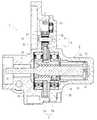
図1は、本発明に係る電動リニアアクチュエータの一実施形態を示す縦断面図、図2は、図1のアクチュエータ本体を示す縦断面図、図3は、図1の中間歯車部を示す要部拡大図、図4は、図3の変形例を示す要部拡大図である。
Hereinafter, embodiments of the present invention will be described in detail with reference to the drawings.
1 is a longitudinal sectional view showing an embodiment of an electric linear actuator according to the present invention, FIG. 2 is a longitudinal sectional view showing an actuator body of FIG. 1, and FIG. 3 is a main portion showing an intermediate gear portion of FIG. FIG. 4 is an enlarged view of a main part showing a modification of FIG.
この電動リニアアクチュエータ1は、図1に示すように、アルミ軽合金からなるハウジング2と、このハウジング2に取り付けられた電動モータ(図示せず)と、この電動モータのモータ軸(図示せず)に取付けられた入力歯車3に噛合する中間歯車4、出力歯車5からなる減速機構6と、この減速機構6を介して電動モータの回転運動を駆動軸7の軸方向の直線運動に変換するボールねじ機構8と、このボールねじ機構8を備えたアクチュエータ本体9とを備えている。
As shown in FIG. 1, the electric linear actuator 1 includes a
ハウジング2は、第1のハウジング2aと、その端面に衝合された第2のハウジング2bとからなり、固定ボルト(図示せず)によって一体に固定されている。第1のハウジング2aには電動モータが取り付けられると共に、これら第1のハウジング2aと第2のハウジング2bの衝合部には、ねじ軸10を収容するための収容孔(貫通孔)11と収容孔(袋孔)12が形成されている。
The
電動モータのモータ軸は、その端部に入力歯車3が圧入により相対回転不能に取り付けられ、第2のハウジング2bに装着された深溝玉軸受からなる転がり軸受13によって回転自在に支持されている。平歯車からなる中間歯車4に噛合する出力歯車5は、後述するボールねじ機構8を構成するナット18にキー14を介して一体に固定されている。
The motor shaft of the electric motor is rotatably supported by a rolling
駆動軸7は、ボールねじ機構8を構成するねじ軸10と一体に構成され、この駆動軸7の一端部(図中右端部)に係止ピン15、15が植設される。ここで、ハウジング2bの収容孔12に装着され、軸方向に延びるガイド溝を有するガイド部材に係止ピン15、15を係合させることにより、ねじ軸10が、回転不可に、かつ軸方向移動可能に支持されている。
The
ボールねじ機構8は、図2に拡大して示すように、ねじ軸10と、このねじ軸10にボール17を介して外挿されたナット18とを備えている。ねじ軸10は、外周に螺旋状のねじ溝10aが形成され、軸方向移動自在に、かつ回転不可に支承されている。一方、ナット18は、ねじ軸10に外装されると共に、内周にねじ軸10のねじ溝10aに対応する螺旋状のねじ溝18aが形成され、これらねじ溝10a、18aとの間に多数のボール17が転動自在に収容されている。そして、ナット18は、ハウジング(図示せず)に対して、2つの支持軸受19、20を介して回転自在に、かつ軸方向移動不可に支承されている。21は、ナット18のねじ溝18aを連結して循環部材を構成する駒部材で、この駒部材21によって多数のボール17が無限循環することができる。
As shown in an enlarged view in FIG. 2, the
各ねじ溝10a、18aの断面形状は、サーキュラアーク形状であってもゴシックアーク形状であっても良いが、ここではボール17との接触角が大きくとれ、アキシアルすきまが小さく設定できるゴシックアーク形状に形成されている。これにより、軸方向荷重に対する剛性が高くなり、かつ振動の発生を抑制することができる。
The cross-sectional shape of each of the
ナット18はSCM415やSCM420等の肌焼き鋼からなり、真空浸炭焼入れによってその表面に55〜62HRCの範囲に硬化処理が施されている。これにより、熱処理後のスケール除去のためのバフ加工等を省略することができ、低コスト化を図ることができる。一方、ねじ軸10はS55C等の中炭素鋼あるいはSCM415やSCM420等の肌焼き鋼からなり、高周波焼入れ、あるいは浸炭焼入れによってその表面に55〜62HRCの範囲に硬化処理が施されている。
The
ナット18の外周面18bには減速機構6を構成する出力歯車5が一体に固定されると共に、この出力歯車5の両側に2つの支持軸受19、20が所定のシメシロを介して圧入されている。これにより、駆動軸7からスラスト荷重が負荷されても支持軸受19、20と出力歯車5の軸方向の位置ズレを防止することができる。また、2つの支持軸受19、20は、両端部にシールド板19a、20aが装着された密封型の深溝玉軸受で構成され、軸受内部に封入された潤滑グリースの外部への漏洩と、外部から摩耗粉等が軸受内部に侵入するのを防止している。
The
ここで、図3に示すように、歯車軸22は第1、第2のハウジング2a、2bに植設され、中間歯車4は、転がり軸受23を介してこの歯車軸22に回転自在に支承されている。歯車軸22の端部のうち、例えば、第1のハウジング2a側の端部を圧入する場合、第2のハウジング2b側の端部をすきまばめに設定することにより、ミスアライメント(組立誤差)を許容して円滑な回転性能を確保することができる。本実施形態では、転がり軸受23は、中間歯車4の内径4aに圧入される鋼板プレス製の外輪24と、保持器25を介して外輪24に転動自在に収容された複数の針状ころ26とを備えた、所謂シェル型の針状ころ軸受で構成されている。これにより、入手性が高く、低コスト化を図ることができる。
Here, as shown in FIG. 3, the
また、中間歯車4の両側にはリング状のワッシャ27、28が装着され、中間歯車4が直接第1、第2のハウジング2a、2bに接触するのを防止している。ここで、中間歯車4の歯部4bの幅が歯幅よりも小さく形成されている。これにより、ワッシャ27、28との接触面積を小さくすることができ、回転時の摩擦抵抗を抑えて円滑な回転性能を得ることができる。ここで、ワッシャ27、28は、強度や耐摩耗性が高いオーステナイト系ステンレス鋼板(JIS規格のSUS304系等)、あるいは防錆処理された冷間圧延鋼板(JIS規格のSPCC系等)からプレス加工にて形成されている。の平ワッシャからなる。なお、これ以外にも、例えば、黄銅や焼結金属、または、GF(グラス繊維)等の繊維状強化材が所定量充填されたPA(ポリアミド)66等の熱可塑性の合成樹脂で形成されていても良い。
Moreover, ring-shaped
さらに、転がり軸受23の幅が中間歯車4の歯幅よりも小さく設定されている。これにより、摩擦による軸受側面の摩耗や変形を防止することができ、円滑な回転性能を得ることができる。
Furthermore, the width of the rolling
図4に、図3の変形例を示す。歯車軸22は第1、第2のハウジング2a、2bに植設され、中間歯車29は、滑り軸受30を介してこの歯車軸22に回転自在に支承されている。本実施形態では、中間歯車29は、歯部29bの幅が歯幅と同一に形成されると共に、滑り軸受30は、中間歯車29の内径29aに圧入され、グラファイト微粉末を添加した多孔質金属からなる含油軸受(NTN株式会社商品名;ベアファイト(登録商標))で構成され、中間歯車29の歯幅よりも大きく設定されている。これにより、ワッシャを装着しなくても中間歯車29が第1、第2のハウジング2a、2bに接触して摩耗するのを防止し、回転時の摩擦抵抗を抑えて円滑な回転性能を得ることができると共に、部品点数増加を抑えて低コスト化を図ることができる。なお、滑り軸受30は、これ以外にも、例えば、射出成形を可能にした熱可塑性ポリイミド樹脂で形成されていても良い。
FIG. 4 shows a modification of FIG. The
以上、本発明の実施の形態について説明を行ったが、本発明はこうした実施の形態に何等限定されるものではなく、あくまで例示であって、本発明の要旨を逸脱しない範囲内において、さらに種々なる形態で実施し得ることは勿論のことであり、本発明の範囲は、特許請求の範囲の記載によって示され、さらに特許請求の範囲に記載の均等の意味、および範囲内のすべての変更を含む。 The embodiment of the present invention has been described above, but the present invention is not limited to such an embodiment, and is merely an example, and various modifications can be made without departing from the scope of the present invention. Of course, the scope of the present invention is indicated by the description of the scope of claims, and further, the equivalent meanings described in the scope of claims and all modifications within the scope of the scope of the present invention are included. Including.
本発明に係る電動リニアアクチュエータは、一般産業用の電動機、自動車等の駆動部に使用され、電動モータからの回転入力を、ボールねじ機構を介して駆動軸の直線運動に変換するボールねじ機構を備えた電動リニアアクチュエータに適用できる。 An electric linear actuator according to the present invention is used in a drive unit of a general industrial electric motor, automobile, etc., and has a ball screw mechanism that converts rotational input from an electric motor into linear motion of a drive shaft via the ball screw mechanism. It can be applied to the provided electric linear actuator.
1 電動リニアアクチュエータ
2 ハウジング
2a 第1のハウジング
2b 第2のハウジング
3 入力歯車
4、29 中間歯車
4a、29a 中間歯車の内径
4b、29b 歯部
5 出力歯車
6 減速機構
7 駆動軸
8 ボールねじ機構
9 アクチュエータ本体
10 ねじ軸
10a、18a ねじ溝
11 収容孔(貫通孔)
12 収容孔(袋孔)
13、23 転がり軸受
14 キー
15 係止ピン
17 ボール
18 ナット
19、20 支持軸受
19a、20a シールド板
21 駒部材
22 歯車軸
24 外輪
25 保持器
26 針状ころ
27、28 ワッシャ
30 滑り軸受
50 電動リニアアクチュエータ
51 ボールねじ
52 アクチュエータ本体
53 電動モータ
53a モータ軸
54 歯車減速機構
55 第1歯車
56 位置保持機構
57 ねじ軸
57a、58a ねじ溝
58 ナット
59 ボール
60 ハウジング
61、62 玉軸受
63 第2歯車
64 シャフト
65 ソレノイド
66 受部
DESCRIPTION OF SYMBOLS 1 Electric
11 Housing hole (through hole)
12 accommodation hole (bag hole)
13, 23 Rolling bearing 14
Claims (6)
このハウジングに取り付けられた電動モータと、
この電動力をモータ軸を介して伝達する減速機構と、
この減速機構を介して前記電動モータの回転運動を駆動軸の軸方向の直線運動に変換するボールねじ機構とを備え、
このボールねじ機構が、前記ハウジングに装着された支持軸受を介して回転可能に、かつ軸方向移動不可に支持され、内周に螺旋状のねじ溝が形成されたナットと、
このナットに多数のボールを介して内挿され、前記駆動軸と同軸状に一体化されて外周に前記ナットのねじ溝に対応する螺旋状のねじ溝が形成され、前記ハウジングに対して回転不可に、かつ軸方向移動可能に支持されたねじ軸とで構成された電動リニアアクチュエータにおいて、
前記ハウジングが第1のハウジングと、その端面に衝合された第2のハウジングとからなり、前記第1のハウジングに前記電動モータが取り付けられ、前記第1のハウジングと第2のハウジングに前記ねじ軸を収容するための収容孔が形成されると共に、
前記減速機構が、前記モータ軸に固定された入力歯車と、この入力歯車に噛合する中間歯車と、この中間歯車に噛合し、前記ナットに一体に固定された出力歯車とを備え、
前記中間歯車が平歯車からなり、前記第1のハウジングと第2のハウジングにそれぞれ植設された歯車軸に軸受を介して回転自在に支承され、この軸受が当該中間歯車の内径に圧入された鋼板製の外輪と、保持器を介して転動自在に収容された複数の針状ころとを備えたシェル型の針状ころ軸受で構成されていることを特徴とする電動リニアアクチュエータ。 A housing;
An electric motor attached to the housing;
A speed reduction mechanism for transmitting this electric force via the motor shaft;
A ball screw mechanism that converts the rotational motion of the electric motor to linear motion in the axial direction of the drive shaft via the speed reduction mechanism;
The ball screw mechanism is rotatably supported via a support bearing mounted on the housing and is not axially movable, and a nut having a helical thread groove formed on the inner periphery,
The nut is inserted through a large number of balls, is integrated coaxially with the drive shaft, and a helical thread groove corresponding to the thread groove of the nut is formed on the outer periphery, and cannot rotate with respect to the housing. And an electric linear actuator composed of a screw shaft supported so as to be axially movable,
The housing includes a first housing and a second housing abutted on an end surface thereof, and the electric motor is attached to the first housing, and the screw is attached to the first housing and the second housing. An accommodation hole for accommodating the shaft is formed,
The speed reduction mechanism includes an input gear fixed to the motor shaft, an intermediate gear meshing with the input gear, and an output gear meshing with the intermediate gear and integrally fixed to the nut;
The intermediate gear is a spur gear, and is rotatably supported via a bearing on gear shafts respectively implanted in the first housing and the second housing, and the bearing is press-fitted into the inner diameter of the intermediate gear. An electric linear actuator comprising a shell-type needle roller bearing including a steel plate outer ring and a plurality of needle rollers housed in a rollable manner via a cage .
Priority Applications (5)
| Application Number | Priority Date | Filing Date | Title |
|---|---|---|---|
| JP2011247259A JP5897874B2 (en) | 2011-11-11 | 2011-11-11 | Electric linear actuator |
| EP12847390.7A EP2778475B1 (en) | 2011-11-11 | 2012-11-12 | Electric linear actuator |
| PCT/JP2012/079311 WO2013069801A1 (en) | 2011-11-11 | 2012-11-12 | Electric linear actuator |
| CN201280055259.5A CN104024695B (en) | 2011-11-11 | 2012-11-12 | Electric linear actuator |
| US14/273,690 US9353838B2 (en) | 2011-11-11 | 2014-05-09 | Electric linear actuator |
Applications Claiming Priority (1)
| Application Number | Priority Date | Filing Date | Title |
|---|---|---|---|
| JP2011247259A JP5897874B2 (en) | 2011-11-11 | 2011-11-11 | Electric linear actuator |
Related Child Applications (1)
| Application Number | Title | Priority Date | Filing Date |
|---|---|---|---|
| JP2016040930A Division JP6312728B2 (en) | 2016-03-03 | 2016-03-03 | Electric linear actuator |
Publications (3)
| Publication Number | Publication Date |
|---|---|
| JP2013104456A JP2013104456A (en) | 2013-05-30 |
| JP2013104456A5 JP2013104456A5 (en) | 2014-12-04 |
| JP5897874B2 true JP5897874B2 (en) | 2016-04-06 |
Family
ID=48290166
Family Applications (1)
| Application Number | Title | Priority Date | Filing Date |
|---|---|---|---|
| JP2011247259A Active JP5897874B2 (en) | 2011-11-11 | 2011-11-11 | Electric linear actuator |
Country Status (5)
| Country | Link |
|---|---|
| US (1) | US9353838B2 (en) |
| EP (1) | EP2778475B1 (en) |
| JP (1) | JP5897874B2 (en) |
| CN (1) | CN104024695B (en) |
| WO (1) | WO2013069801A1 (en) |
Families Citing this family (13)
| Publication number | Priority date | Publication date | Assignee | Title |
|---|---|---|---|---|
| CN106102956A (en) * | 2014-01-16 | 2016-11-09 | 亨罗布有限公司 | Clinching method |
| EP3190927B1 (en) * | 2014-09-09 | 2019-05-15 | Linak A/S | Linear dual actuator |
| CA2970637A1 (en) * | 2014-11-10 | 2016-05-19 | Creative Motion Control, Inc. | Tool with linear drive mechanism, dual speed gearbox and elastomeric control system |
| JP6527705B2 (en) * | 2015-02-02 | 2019-06-05 | Ntn株式会社 | Electric actuator |
| US10024450B2 (en) * | 2015-11-25 | 2018-07-17 | Woodward, Inc. | High speed shutdown device for electric actuator |
| CN105337447A (en) * | 2015-11-27 | 2016-02-17 | 湖北三江航天红峰控制有限公司 | Pancake electric steering engine |
| JP6312728B2 (en) * | 2016-03-03 | 2018-04-18 | Ntn株式会社 | Electric linear actuator |
| JP6779645B2 (en) * | 2016-03-30 | 2020-11-04 | Ntn株式会社 | Electric actuator |
| DE102017131096A1 (en) | 2017-12-22 | 2019-06-27 | Lucas Automotive Gmbh | Gear assembly for a geared motor of an electrically actuated brake, gear motor, parking brake system and service brake system |
| EP3557096B1 (en) * | 2018-04-20 | 2022-04-13 | SFS Group International AG | Imbalance compensation method und ball screw drive with power transmission element according to this method |
| DE102018123042A1 (en) * | 2018-09-19 | 2020-03-19 | Fte Automotive Gmbh | Electrical clutch actuator with spring-loaded pressure piece |
| KR102167914B1 (en) * | 2019-05-14 | 2020-10-20 | 주식회사 만도 | Steering Apparatus for Vehicle |
| US11333229B2 (en) * | 2020-03-17 | 2022-05-17 | ZF Active Safety US Inc. | Roller screw system |
Family Cites Families (40)
| Publication number | Priority date | Publication date | Assignee | Title |
|---|---|---|---|---|
| US1865842A (en) * | 1928-11-12 | 1932-07-05 | Emsco Derrick & Equip Co | Sheave assembly |
| US2403092A (en) * | 1943-02-19 | 1946-07-02 | Lear Inc | Linear actuator |
| FR951949A (en) * | 1947-08-09 | 1949-11-07 | Auxiliaire Ind L | Screw jack, with reversible motor, and emergency exit of the rod |
| FR1588166A (en) * | 1967-07-06 | 1970-04-10 | ||
| GB1313651A (en) * | 1969-06-25 | 1973-04-18 | Nat Res Dev | Bearing component |
| US4274292A (en) * | 1979-10-11 | 1981-06-23 | Arnett Jr Robert D | Compact starter assembly |
| JPS6333026A (en) | 1986-07-28 | 1988-02-12 | Hitachi Ltd | Synchronizing establishing system for spread spectrum receiver |
| JPS6333026U (en) * | 1986-08-20 | 1988-03-03 | ||
| US4998346A (en) * | 1989-04-12 | 1991-03-12 | Ina Bearing Company | Method of making a unitary, axially self-locating needle bearing |
| US5063808A (en) * | 1990-04-23 | 1991-11-12 | Emerson Electric Co. | Linear actuator improvement to prevent "back driving" |
| KR920005683Y1 (en) * | 1990-06-28 | 1992-08-20 | 주식회사 비앤앨 | Electrially operated screw-type jack for vehicle |
| JP3067542B2 (en) * | 1994-09-30 | 2000-07-17 | 矢崎総業株式会社 | Gear device for transmission |
| JPH0988965A (en) * | 1995-09-26 | 1997-03-31 | Ntn Corp | Heat resistant sliding bearing |
| JP2000145914A (en) * | 1998-11-17 | 2000-05-26 | Tsubakimoto Chain Co | Bearing linear actuator with backstop mechanism |
| JP2001065575A (en) * | 1999-08-24 | 2001-03-16 | Nippon Thompson Co Ltd | Shell type needle roller bearing |
| JP2003002219A (en) * | 2001-06-27 | 2003-01-08 | Nsk Ltd | Electric power steering device |
| US7284634B2 (en) * | 2001-04-13 | 2007-10-23 | Nsk, Ltd. | Electric power steering apparatus |
| JP2004028169A (en) * | 2002-06-24 | 2004-01-29 | Smc Corp | Electric actuator |
| DE10334880A1 (en) * | 2003-07-29 | 2005-03-03 | Ina-Schaeffler Kg | Thrust washer for planetary gear |
| EP1659303A1 (en) * | 2003-08-25 | 2006-05-24 | Hitachi Construction Machinery Co., Ltd. | Sliding bearing assembly and sliding bearing |
| WO2005121288A1 (en) * | 2004-06-10 | 2005-12-22 | Ntn Corporation | Sliding material and sliding bearing |
| JP2006125516A (en) * | 2004-10-28 | 2006-05-18 | Ntn Corp | Oil-retaining sintered bearing |
| JP2007032703A (en) * | 2005-07-27 | 2007-02-08 | Ntn Corp | Electric linear actuator |
| JP4697785B2 (en) * | 2005-08-08 | 2011-06-08 | Ntn株式会社 | Electric linear actuator |
| US7560888B2 (en) * | 2005-09-08 | 2009-07-14 | Honeywell International Inc. | Electromechanical actuator including redundant, dissimilar position feedback |
| ITTO20060110A1 (en) * | 2006-02-16 | 2007-08-17 | Skf Ab | LINEAR ELECTROMECHANICAL ACTUATOR FOR A PARKING BRAKE. |
| US8220153B2 (en) * | 2006-05-26 | 2012-07-17 | Hitachi Powdered Metals Co., Ltd. | Production method for complex bearing |
| JP4883349B2 (en) * | 2006-06-27 | 2012-02-22 | 株式会社ジェイテクト | Electric power steering device |
| JP2008024052A (en) * | 2006-07-18 | 2008-02-07 | Ntn Corp | Supporting structure for suspension device |
| JP5218817B2 (en) * | 2007-05-17 | 2013-06-26 | 日本精工株式会社 | Actuator |
| US8297142B2 (en) | 2007-03-22 | 2012-10-30 | Nsk Ltd. | Actuator |
| JP2008257145A (en) * | 2007-04-09 | 2008-10-23 | Nikon Corp | Frictional member for braking mechanism and shutter mechanism |
| JP5340561B2 (en) * | 2007-06-15 | 2013-11-13 | Ntn株式会社 | Tapered roller bearing |
| JP5243018B2 (en) | 2007-12-27 | 2013-07-24 | Ntn株式会社 | Electric linear actuator |
| JP2009250316A (en) * | 2008-04-03 | 2009-10-29 | Ntn Corp | Cage for rolling bearing |
| JP5324819B2 (en) * | 2008-05-12 | 2013-10-23 | シマノコンポネンツ マレーシア エスディーエヌ.ビーエッチディー. | Lever drag reel reverse rotation prevention mechanism |
| JP5440326B2 (en) * | 2010-03-30 | 2014-03-12 | 株式会社ジェイテクト | Transmission gear device and manufacturing method thereof |
| EP2520829B1 (en) * | 2010-04-26 | 2016-03-02 | NSK Ltd. | Linear actuator |
| DK2383480T3 (en) * | 2010-04-30 | 2013-01-21 | Winergy Ag | Planetary gear for a wind turbine |
| JP5918510B2 (en) * | 2011-11-16 | 2016-05-18 | Ntn株式会社 | Electric linear actuator |
-
2011
- 2011-11-11 JP JP2011247259A patent/JP5897874B2/en active Active
-
2012
- 2012-11-12 EP EP12847390.7A patent/EP2778475B1/en active Active
- 2012-11-12 CN CN201280055259.5A patent/CN104024695B/en active Active
- 2012-11-12 WO PCT/JP2012/079311 patent/WO2013069801A1/en active Application Filing
-
2014
- 2014-05-09 US US14/273,690 patent/US9353838B2/en not_active Expired - Fee Related
Also Published As
| Publication number | Publication date |
|---|---|
| EP2778475A1 (en) | 2014-09-17 |
| US20140245848A1 (en) | 2014-09-04 |
| WO2013069801A1 (en) | 2013-05-16 |
| EP2778475B1 (en) | 2019-10-09 |
| EP2778475A4 (en) | 2016-08-31 |
| CN104024695B (en) | 2017-04-12 |
| US9353838B2 (en) | 2016-05-31 |
| JP2013104456A (en) | 2013-05-30 |
| CN104024695A (en) | 2014-09-03 |
Similar Documents
| Publication | Publication Date | Title |
|---|---|---|
| JP5897874B2 (en) | Electric linear actuator | |
| JP5918510B2 (en) | Electric linear actuator | |
| JP6111042B2 (en) | Electric linear actuator | |
| JP6091149B2 (en) | Electric linear actuator | |
| JP5562795B2 (en) | Electric actuator | |
| JP2013104525A5 (en) | ||
| JP5719717B2 (en) | Electric linear actuator | |
| JP2013104456A5 (en) | ||
| WO2013191066A1 (en) | Electric linear actuator | |
| JP2014137124A (en) | Electric linear actuator | |
| JP6312728B2 (en) | Electric linear actuator | |
| JP5924899B2 (en) | Electric linear actuator | |
| JP2016151332A (en) | Ball screw and electric linear actuator having the same | |
| WO2016195104A1 (en) | Electric actuator | |
| JP2012039765A (en) | Electric actuator | |
| JP6111038B2 (en) | Electric linear actuator | |
| JP5982220B2 (en) | Electric linear actuator | |
| JP6114548B2 (en) | Electric linear actuator | |
| JP6121760B2 (en) | Electric linear actuator | |
| JP2008069793A (en) | Electric linear actuator | |
| JP2016161087A (en) | Electric linear actuator | |
| JP6111041B2 (en) | Electric linear actuator | |
| JP6130235B2 (en) | Electric linear actuator |
Legal Events
| Date | Code | Title | Description |
|---|---|---|---|
| A521 | Request for written amendment filed |
Free format text: JAPANESE INTERMEDIATE CODE: A523 Effective date: 20141017 |
|
| A621 | Written request for application examination |
Free format text: JAPANESE INTERMEDIATE CODE: A621 Effective date: 20141017 |
|
| A131 | Notification of reasons for refusal |
Free format text: JAPANESE INTERMEDIATE CODE: A131 Effective date: 20150814 |
|
| A521 | Request for written amendment filed |
Free format text: JAPANESE INTERMEDIATE CODE: A523 Effective date: 20151009 |
|
| TRDD | Decision of grant or rejection written | ||
| A01 | Written decision to grant a patent or to grant a registration (utility model) |
Free format text: JAPANESE INTERMEDIATE CODE: A01 Effective date: 20160205 |
|
| A61 | First payment of annual fees (during grant procedure) |
Free format text: JAPANESE INTERMEDIATE CODE: A61 Effective date: 20160303 |
|
| R150 | Certificate of patent or registration of utility model |
Ref document number: 5897874 Country of ref document: JP Free format text: JAPANESE INTERMEDIATE CODE: R150 |
|
| R250 | Receipt of annual fees |
Free format text: JAPANESE INTERMEDIATE CODE: R250 |
|
| R250 | Receipt of annual fees |
Free format text: JAPANESE INTERMEDIATE CODE: R250 |
|
| R250 | Receipt of annual fees |
Free format text: JAPANESE INTERMEDIATE CODE: R250 |
|
| R250 | Receipt of annual fees |
Free format text: JAPANESE INTERMEDIATE CODE: R250 |
|
| R250 | Receipt of annual fees |
Free format text: JAPANESE INTERMEDIATE CODE: R250 |
|
| R250 | Receipt of annual fees |
Free format text: JAPANESE INTERMEDIATE CODE: R250 |