EP3540920A1 - Linear electric actuator - Google Patents
Linear electric actuator Download PDFInfo
- Publication number
- EP3540920A1 EP3540920A1 EP17870606.5A EP17870606A EP3540920A1 EP 3540920 A1 EP3540920 A1 EP 3540920A1 EP 17870606 A EP17870606 A EP 17870606A EP 3540920 A1 EP3540920 A1 EP 3540920A1
- Authority
- EP
- European Patent Office
- Prior art keywords
- electric actuator
- linear electric
- screw
- electric motor
- rotor inner
- Prior art date
- Legal status (The legal status is an assumption and is not a legal conclusion. Google has not performed a legal analysis and makes no representation as to the accuracy of the status listed.)
- Withdrawn
Links
Images


Classifications
-
- F—MECHANICAL ENGINEERING; LIGHTING; HEATING; WEAPONS; BLASTING
- F16—ENGINEERING ELEMENTS AND UNITS; GENERAL MEASURES FOR PRODUCING AND MAINTAINING EFFECTIVE FUNCTIONING OF MACHINES OR INSTALLATIONS; THERMAL INSULATION IN GENERAL
- F16H—GEARING
- F16H13/00—Gearing for conveying rotary motion with constant gear ratio by friction between rotary members
- F16H13/06—Gearing for conveying rotary motion with constant gear ratio by friction between rotary members with members having orbital motion
- F16H13/08—Gearing for conveying rotary motion with constant gear ratio by friction between rotary members with members having orbital motion with balls or with rollers acting in a similar manner
-
- F—MECHANICAL ENGINEERING; LIGHTING; HEATING; WEAPONS; BLASTING
- F16—ENGINEERING ELEMENTS AND UNITS; GENERAL MEASURES FOR PRODUCING AND MAINTAINING EFFECTIVE FUNCTIONING OF MACHINES OR INSTALLATIONS; THERMAL INSULATION IN GENERAL
- F16H—GEARING
- F16H25/00—Gearings comprising primarily only cams, cam-followers and screw-and-nut mechanisms
- F16H25/18—Gearings comprising primarily only cams, cam-followers and screw-and-nut mechanisms for conveying or interconverting oscillating or reciprocating motions
- F16H25/20—Screw mechanisms
- F16H25/22—Screw mechanisms with balls, rollers, or similar members between the co-operating parts; Elements essential to the use of such members
-
- F—MECHANICAL ENGINEERING; LIGHTING; HEATING; WEAPONS; BLASTING
- F16—ENGINEERING ELEMENTS AND UNITS; GENERAL MEASURES FOR PRODUCING AND MAINTAINING EFFECTIVE FUNCTIONING OF MACHINES OR INSTALLATIONS; THERMAL INSULATION IN GENERAL
- F16H—GEARING
- F16H35/00—Gearings or mechanisms with other special functional features
- F16H35/10—Arrangements or devices for absorbing overload or preventing damage by overload
-
- H—ELECTRICITY
- H02—GENERATION; CONVERSION OR DISTRIBUTION OF ELECTRIC POWER
- H02K—DYNAMO-ELECTRIC MACHINES
- H02K7/00—Arrangements for handling mechanical energy structurally associated with dynamo-electric machines, e.g. structural association with mechanical driving motors or auxiliary dynamo-electric machines
- H02K7/06—Means for converting reciprocating motion into rotary motion or vice versa
Definitions
- the present invention relates to a linear electric actuator.
- Patent Document 1 An actuator using a ball screw mechanism in order to convert a rotary motion of the electric motor into a motion in a linear direction
- Patent Document 1 JP 2014-18007 A
- Patent Document 1 there is proposed a linear electric actuator in which a nut of the ball screw and a rotor of the electric motor are integrated so that the rotor of the electric motor has a function of the nut of the ball screw, and the rotor is supported by a rolling bearing.
- the electric motor and the ball screw are arranged coaxially with each other, and the rotor of the electric motor and the nut of the ball screw overlap each other in a radial direction.
- a screw shaft and a dragging rod are integrally coupled to each other to form a rotation stopper mechanism between the dragging rod and a motor case end portion.
- the rotation stopper mechanism is formed between the dragging rod, which extends to the outside of the motor case, and the motor case, and hence an axial dimension of the linear electric actuator becomes larger. Therefore, it was found that there is a problem on a mounting space depending on use.
- the present invention has an object to achieve downsizing and improvement in mountability of a linear electric actuator in which an electric motor part and a screw mechanism part are coaxially arranged.
- the inventors of the present invention have arrived at a novel idea in such a manner that a rotor inner of an electric motor part and a nut of a screw mechanism part of a linear electric actuator are positioned so as to be prevented from overlapping with each other in an axial direction to downsize the linear electric actuator in a radial direction and a rotation stopper mechanism for a screw shaft of the screw mechanism part is provided through efficient use of an inner space of the rotor inner.
- a linear electric actuator comprising: an electric motor part; a screw mechanism part; and an operation part, the electric motor part and the screw mechanism part being coaxially arranged, a rotary motion of a hollow rotor inner of the electric motor part being transmitted to a nut of the screw mechanism part, the operation part being provided to a screw shaft of the screw mechanism part, wherein the hollow rotor inner and the nut are positioned so as to be prevented from overlapping each other in an axial direction, and wherein a rotation stopper mechanism for the screw shaft is provided on a radially inner side of the hollow rotor inner.
- the rotation stopper mechanism for the screw shaft comprises a pin fitted to the screw shaft and a guide member having a guide groove, a structure of the rotation stopper mechanism can be simplified.
- the screw mechanism part is formed of a ball screw, a highly accurate and smooth linear motion can be achieved.
- the linear electric actuator further comprise a speed reducer provided between the hollow rotor inner and the nut.
- the electric motor can be downsized, thereby being capable of achieving reduction in size and weight of the linear electric actuator.
- the above-mentioned speed reducer comprise a planetary speed reducer of a traction drive type. With this, reduction in noise without backlash can be achieved.
- the linear electric actuator further comprise a hollow output shaft provided on a radially inner side of the hollow rotor inner; and a torque limiter provided between the hollow rotor inner and the hollow output shaft.
- downsizing in particular, downsizing in the radial direction of the linear electric actuator in which the electric motor part and the screw mechanism part are coaxially arranged is achieved, thereby being capable of improving mountability.
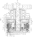
- FIG. 1 is a vertical sectional view for illustrating a linear electric actuator according to this embodiment as viewed from a direction indicated by the arrows of the line H-H of FIG. 3 and FIG. 6 .
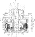
- FIG. 2 is a vertical sectional view as viewed from a direction indicated by the arrows of the line I-I of FIG. 6 .
- the linear electric actuator 1 mainly comprises an electric motor part A configured to generate a driving force, a screw mechanism part B configured to convert a rotary motion of the electric motor part A into a linear motion and output the linear motion, and an operation part C configured to output the motion of the screw mechanism part B.
- the electric motor part A is formed of a radial gap electric motor 29.
- the radial gap electric motor 29 comprises a stator 51 and a rotor 52.
- the stator 51 is fixed to a casing 8.
- the rotor 52 is arranged so as to be opposed to a radially inner side of the stator 51 with a gap.
- the stator 51 comprises a stator core 51a, a bobbin 51b, and a coil 51c.
- the stator core 51a is formed of a plurality of electromagnetic steel plates stacked in the axial direction.
- the bobbin 51b is made of an insulating material and is mounted to the stator core 51a.
- the coil 51c is wound around the bobbin 51b.
- the rotor 52 comprises a rotor core 52a, a plurality of magnets 52b, and a rotor inner (hereinafter also referred to as "hollow rotor inner") 52c.
- the rotor core 52a has an annular shape.
- the plurality of magnets 52b are mounted to an outer periphery of the rotor core 52a.
- the rotor inner 52c has an annular shape and is fixed to an inner periphery of the rotor core 52a.
- the rotor core 52a is formed of a plurality of electromagnetic steel plates stacked in the axial direction.
- An axial length of the rotor inner 52c is larger than an axial length of the rotor core 52a, and the rotor inner 52c is configured to project from both sides of the rotor core 52a in the axial direction.
- the casing 8 is divided at one position or a plurality of positions in the axial direction.
- the casing 8 is divided into a bottom portion 81 having a bottomed cylindrical shape, a tubular portion 82 being opened at both ends, a pressurizing portion 84, and a cover portion 85.
- the pressurizing portion 84 and the cover portion 85 are arranged on one side of the tubular portion 82 in the axial direction (right side of FIG. 1 and FIG. 2 ), and the bottom portion 81 is arranged on another side of the tubular portion 82 in the axial direction (left side of FIG. 1 and FIG. 2 ).
- the bottom portion 81, the tubular portion 82, the pressurizing portion 84, and the cover portion 85 are fastened and integrated to one another through use of bolts 86.
- the cover portion 85 comprises, on one side in the axial direction, flange portions 85a for mounting to a device to be used (not shown), and the flange portions 85a have bolt insertion holes 85b.
- a terminal part D is provided in the bottom portion 81 of the casing 8, and a connector 101 of the terminal part D projects outward from the bottom portion 81.
- Terminals for motive power supply and signal lines in the connector 101 are connected to, for example, the coil 51c of the stator 51 and sensors.
- Rolling bearings 53 and 54 are mounted to outer peripheral surfaces at both end portions of the rotor inner 52c in the axial direction, and the rotor inner 52c is supported by the rolling bearings 53 and 54 on the tubular portion 82 and the bottom portion 81 of the casing 8 so as to be freely rotatable.
- the rolling bearings 53 and 54 are deep-groove ball bearings, and are configured to support both a radial load and a thrust load.
- the rotor inner 52c has a hollow shape, and an output shaft 6 having a hollow shape is provided along an inner peripheral surface of the rotor inner 52c.
- An outer peripheral surface of the hollow output shaft 6 is fitted to the inner peripheral surface of the hollow rotor inner 52c by clearance fitting, and the hollow output shaft 6 is rotatable relative to the hollow rotor inner 52c.
- An annular recess portion 521 having an inner diameter dimension larger than that of other portions is formed in the inner peripheral surface of the rotor inner 52c on the another side in the axial direction (left side of FIG. 1 and FIG. 2 ), and a female spline (including serration) 522 extending in the axial direction is formed in an inner peripheral surface of the annular recess portion 521.
- a male spline (including serration) 6a extending in the axial direction is formed in the outer peripheral surface of the hollow output shaft 6 on the another side in the axial direction (left side of FIG. 1 and FIG. 2 ).
- An annular space is defined between the inner peripheral surface of the annular recess portion 521 of the rotor inner 52c and the outer peripheral surface of the hollow output shaft 6 opposed thereto.
- a torque limiter 7 is arranged in the annular space. The torque limiter 7 is configured to prevent application of excessive load on components of the linear electric actuator 1 to thereby prevent damage on the components, and details thereof are described later.
- the linear electric actuator 1 comprises a speed reducer 2, which is provided between the hollow rotor inner 52c of the electric motor 29, specifically, the hollow output shaft 6 fitted to the hollow rotor inner 52c and a nut of the screw mechanism part B described later, and a rotary force with high torque having been reduced in speed is transmitted from the speed reducer 2 to the screw mechanism part B.
- the electric motor 29 can be downsized, thereby achieving reduction in size and weight of the linear electric actuator 1.
- a planetary speed reducer of a traction drive type is used as the speed reducer 2.
- the speed reducer 2 of the traction drive type are described later.
- the screw mechanism part B is formed of a ball screw 91.
- the ball screw 91 mainly comprises a nut 92, a screw shaft 93, a large number of balls 94, and rollers (not shown) being circulation members.
- the nut 92 has a spiral groove formed in an inner peripheral surface thereof, and the screw shaft 93 has a spiral groove formed in an outer peripheral surface thereof.
- the balls 94 are placed between the spiral grooves.
- the nut 92 is supported on the cover portion 85 of the casing 8 so as to be freely rotatable by a double-row rolling bearing 96 mounted to an outer peripheral surface thereof.
- a carrier 24 serving as an output side of the speed reducer 2 is coupled to an outer peripheral surface of the nut 92 by press-fitting in a torque-transmittable manner.
- a rotation stopper mechanism M for the screw shaft 93 is provided to the screw shaft 93 on the another side in the axial direction (left side of FIG. 1 and FIG. 2 ). With this, when the nut 92 rotates, the screw shaft 93 proceeds and retreats in the right-and-left direction of FIG. 1 and FIG. 2 .
- An actuator head 100 serving as the operation part C is integrally provided to the screw shaft 93 on the one side in the axial direction (right side of FIG. 1 and FIG. 2 ).
- the actuator head 100 of the operation part C may be in various modes such as a mode in which the actuator head 100 is formed separately from the screw shaft 93 or a mode in which the actuator head 100 has a coupling structure with respect to corresponding parts of a device to be used. Details of the rotation stopper mechanism M are described later.
- the overall configuration of the linear electric actuator 1 according to this embodiment is as described above. Next, a characteristic configuration and an advantageous configuration are described in detail.
- the hollow rotor inner 52c and the nut 92 are positioned so as to be prevented from overlapping each other in the axial direction, and the rotation stopper mechanism M for the screw shaft 93 is provided on a radially inner side of the hollow rotor inner 52c.
- the hollow rotor inner 52c of the electric motor 29 and the hollow output shaft 6 coupled to the hollow rotor inner 52c through intermediation of the torque limiter 7 are positioned so as to be prevented from overlapping the nut 92 of the ball screw 91 in the axial direction.
- the electric motor part A and the screw mechanism part B are coaxially arranged, but the nut 92 of the ball screw 91 is prevented from overlapping the hollow rotor inner 52c and the hollow output shaft 6 in the radial direction. Therefore, an inner diameter D1 of the hollow rotor inner 52c and an inner diameter D2 of the hollow output shaft 6 can be set smaller than an outer diameter D3 of the nut 92 of the ball screw 91. With this, the small-sized electric motor 29 can be used, thereby being capable of achieving downsizing, in particular, downsizing of the radial dimension of the linear electric actuator 1.
- the screw shaft 93 of the ball screw 91 is accommodated so that an overall axial dimension is also downsized. Further, through efficient use of the inner space described above, the rotation stopper mechanism M is provided to the screw shaft 93 on the another side in the axial direction (left side of FIG. 1 and FIG. 2 ).
- the rotation stopper mechanism M for the screw shaft 93 comprises a guide member 95, a pin 96 fitted to a hole passing through the screw shaft 93 in the radial direction, and a guide collar 97 externally fitted to the pin 96 so as to be freely rotatable.
- the guide member 95 is fixed to the bottom portion 81 of the casing 8, and a cylindrical portion 95a of the guide member 95 is arranged between the inner peripheral surface of the hollow output shaft 6 and the outer peripheral surface of the screw shaft 93.
- a guide groove 95b is formed on an inner side of the cylindrical portion 95a, and the guide collar 97 is fitted to the guide groove 95b.
- the guide collar 97 is made of a resin material such as PPS, and enables smooth rotation. With this, when the nut 92 rotates, the screw shaft 93 smoothly proceeds and retreats in the right-and-left direction of FIG. 1 and FIG. 2 .
- guide surfaces of the guide groove 95b on which the guide collar 97 is guided are formed of two parallel surfaces.
- the present invention is not limited to this configuration. There may be provided guide surfaces formed of two surfaces having an angle in a V-shape or a guide surface having a cylindrical shape, and the outer peripheral surface of the guide collar 97 may be formed into a shape corresponding to the guide surface.
- the guide collar 97 is made of a resin material.
- the guide collar 97 may be made of metal. Further, the guide collar 97 may be omitted, and the pin 96 may be directly engaged with the guide groove 95b.
- the configuration described in Claims in which the rotation stopper mechanism for the screw shaft is provided on the radially inner side of the hollow rotor inner, in a case of this embodiment in which the hollow output shaft is coupled to the hollow rotor inner through intermediation of the torque limiter, the configuration corresponds to the structure in which the rotation stopper mechanism for the screw shaft is provided on the radially inner side of the hollow output shaft to be fitted to the inner side of the hollow rotor inner.
- the configuration described in Claims encompasses such case.
- the torque limiter 7 is configured to transmit a rotary motive force output from the electric motor 29 to the hollow output shaft 6, and block transmission of torque when an excessive load acts thereon, thereby allowing relative rotation between the electric motor 29 and the hollow output shaft 6.
- any torque limiter 7 having a freely selected configuration may be used. In this embodiment, illustration is given of the case in which a friction clutch 7 is used as one example of the torque limiter 7.
- the friction clutch 7 comprises a pair of first friction plates 71, a second friction plate 73 incorporated between the pair of first friction plates 71, a pressing plate 75, and an elastic member 74.
- the elastic member 74 such as a corrugated spring is interposed between the pressing plate 75 and the first friction plates 71 to bring the first friction plates 71 and the second friction plate 73 into press contact.
- the pressing plate 75 is positioned in the axial direction by a stopper ring 76 locked to an annular groove of the inner peripheral surface of the rotor inner 52c.
- the first friction plates 71 are fitted to the female spline 522 of the rotor inner 52c by spline fitting and coupled thereto in a torque-transmittable manner.
- the pressing plate 75 is also fitted to the female spline 522 of the rotor inner 52c by spline fitting.
- the second friction plate 73 is fitted to the male spline 6a of the hollow output shaft 6 by spline fitting and coupled thereto in a torque-transmittable manner.
- the first friction plates 71 and the second friction plate 73 are movable relative to the female spline 522 and the male spline 6a in the axial direction, and an urging force of the elastic member 74 generates a friction force between the first friction plates 71 and the second friction plate 73. Further, a large number of friction members 73a are mounted to the second friction plate 73 so as to be arrayed in a circumferential direction, thereby being capable of obtaining a stable friction force with respect to the first friction plates 71.
- the planetary speed reducer 2 of the traction drive type mainly comprises a sun roller 21, an outer ring 22, a plurality of planetary rollers 23, and the carrier 24 (see FIG. 2 ).
- An end portion of the hollow output shaft 6 is used as the sun roller 21, and rolling bearings 25 (for example, deep-groove ball bearings) are used as the planetary rollers 23.
- An inner ring of each of the rolling bearings 25 being the planetary rollers 23 is press-fitted and fixed to a shaft 26 of the carrier 24.
- the outer ring 22 comprises a main body portion 22a and a flange portion 22b.
- the main body portion 22a has a U-shaped section.
- the flange portion 22b projects from both sides of the main body portion 22a in the axial direction.
- the outer ring 22 accommodated along the inner periphery of the tubular portion 82 allows the flange portion 22b on the one side in the axial direction (right side of FIG. 1 and FIG. 2 ) to project with respect to an end surface of the tubular portion 82.
- the pressurizing portion 84 together with the cover portion 85, is pressed so as to be brought into abutment against the end surface of the tubular portion 82 and both the components are connected to each other through use of the bolts 86, the outer ring 22 having been pressed by the pressurizing portion 84 is elastically deformed so that the main body portion 22a expands toward the radially inner side.
- a preload is applied to a contact portion between the outer ring 22 and the planetary rollers 23 as well as to a contact portion between the planetary rollers 23 and the sun roller 21.
- an adjustment member (shim) 28 having a ring shape.
- the preload can be set within a predetermined range.
- the outer peripheral surface of the nut 92 of the ball screw 91 is coupled to the inner peripheral surface of the carrier 24 being the output side of the speed reducer 2 by press-fitting in a torque-transmittable manner.
- FIG. 7 is a perspective view as viewed from the left side of FIG. 2
- FIG. 8 is a perspective view as viewed from the right side of FIG. 2 . It can be understood that the linear electric actuator 1 according to this embodiment is efficiently downsized, in particular, in radial dimension and is excellent in mountability.
- the present invention is not limited to this configuration.
- the screw mechanism part may be formed of a slide screw.
- illustration is given of a radial gap electric motor as the electric motor 29 of the electric motor part A.
- the present invention is not limited to this, and there may be used an axial gap motor.
Abstract
Description
- The present invention relates to a linear electric actuator.
- In recent years, in order to attain power saving and reduction in fuel consumption of a vehicle or the like, motorization has been promoted. For example, a system of performing operations of an automatic transmission, a brake, and a steering wheel of an automobile using power of an electric motor has been developed, and brought into market. As an actuator used for such applications, there has been known an actuator using a ball screw mechanism in order to convert a rotary motion of the electric motor into a motion in a linear direction (Patent Document 1).
- Patent Document 1:
JP 2014-18007 A - In
Patent Document 1, there is proposed a linear electric actuator in which a nut of the ball screw and a rotor of the electric motor are integrated so that the rotor of the electric motor has a function of the nut of the ball screw, and the rotor is supported by a rolling bearing. In this linear electric actuator, the electric motor and the ball screw are arranged coaxially with each other, and the rotor of the electric motor and the nut of the ball screw overlap each other in a radial direction. Moreover, a screw shaft and a dragging rod are integrally coupled to each other to form a rotation stopper mechanism between the dragging rod and a motor case end portion. - In the linear electric actuator of
Patent Document 1, the rotor of the electric motor and the nut of the ball screw overlap each other in the radial direction. As a result of research on actual use, it was found that there is a limit in use when a mounting space in the radial direction is small. - Moreover, the rotation stopper mechanism is formed between the dragging rod, which extends to the outside of the motor case, and the motor case, and hence an axial dimension of the linear electric actuator becomes larger. Therefore, it was found that there is a problem on a mounting space depending on use.
- In view of the problems described above, the present invention has an object to achieve downsizing and improvement in mountability of a linear electric actuator in which an electric motor part and a screw mechanism part are coaxially arranged.
- As a result of extensive studies conducted to achieve the object described above, the inventors of the present invention have arrived at a novel idea in such a manner that a rotor inner of an electric motor part and a nut of a screw mechanism part of a linear electric actuator are positioned so as to be prevented from overlapping with each other in an axial direction to downsize the linear electric actuator in a radial direction and a rotation stopper mechanism for a screw shaft of the screw mechanism part is provided through efficient use of an inner space of the rotor inner.
- According to one embodiment of the present invention, as technical measures for achieving the above-mentioned object, there is provided a linear electric actuator, comprising: an electric motor part; a screw mechanism part; and an operation part, the electric motor part and the screw mechanism part being coaxially arranged, a rotary motion of a hollow rotor inner of the electric motor part being transmitted to a nut of the screw mechanism part, the operation part being provided to a screw shaft of the screw mechanism part, wherein the hollow rotor inner and the nut are positioned so as to be prevented from overlapping each other in an axial direction, and wherein a rotation stopper mechanism for the screw shaft is provided on a radially inner side of the hollow rotor inner.
- With the configuration described above, downsizing, in particular, downsizing in the radial direction of the linear electric actuator in which the electric motor part and the screw mechanism part are coaxially arranged is achieved, thereby being capable of improving mountability.
- When the rotation stopper mechanism for the screw shaft comprises a pin fitted to the screw shaft and a guide member having a guide groove, a structure of the rotation stopper mechanism can be simplified.
- When the screw mechanism part is formed of a ball screw, a highly accurate and smooth linear motion can be achieved.
- It is preferred that the linear electric actuator further comprise a speed reducer provided between the hollow rotor inner and the nut. With this, the electric motor can be downsized, thereby being capable of achieving reduction in size and weight of the linear electric actuator.
- It is preferred that the above-mentioned speed reducer comprise a planetary speed reducer of a traction drive type. With this, reduction in noise without backlash can be achieved.
- It is preferred that the linear electric actuator further comprise a hollow output shaft provided on a radially inner side of the hollow rotor inner; and a torque limiter provided between the hollow rotor inner and the hollow output shaft. With this, application of excessive load on components of the linear electric actuator is prevented, thereby being capable of preventing damage on the components.
- According to the present invention, downsizing, in particular, downsizing in the radial direction of the linear electric actuator in which the electric motor part and the screw mechanism part are coaxially arranged is achieved, thereby being capable of improving mountability.
-
-
FIG. 1 is a vertical sectional view for illustrating a linear electric actuator according to one embodiment of the present invention as viewed from a direction indicated by the arrows of the line H-H ofFIG. 3 andFIG. 6 . -
FIG. 2 is a vertical sectional view for illustrating the linear electric actuator according to the one embodiment of the present invention as viewed from a direction indicated by the arrows of the line I-I ofFIG. 6 . -
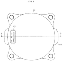
FIG. 3 is a left side view ofFIG. 1 . -
FIG. 4 is a transverse sectional view as viewed from a direction indicated by the arrows of the line E-E ofFIG. 1 . -
FIG. 5 is a transverse sectional view as viewed from a direction indicated by the arrows of the line F-F ofFIG. 1 . -
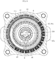
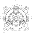
FIG. 6 is a transverse sectional view as viewed from a direction indicated by the arrows of the line G-G ofFIG. 2 . -
FIG. 7 is a perspective view as viewed from a left side ofFIG. 2 . -
FIG. 8 is a perspective view as viewed from a right side ofFIG. 2 . - A linear electric actuator according to one embodiment of the present invention is described with reference to
FIG. 1 to FIG. 8 .FIG. 1 is a vertical sectional view for illustrating a linear electric actuator according to this embodiment as viewed from a direction indicated by the arrows of the line H-H ofFIG. 3 andFIG. 6 .FIG. 2 is a vertical sectional view as viewed from a direction indicated by the arrows of the line I-I ofFIG. 6 . - As illustrated in
FIG. 1 andFIG. 2 , the linearelectric actuator 1 mainly comprises an electric motor part A configured to generate a driving force, a screw mechanism part B configured to convert a rotary motion of the electric motor part A into a linear motion and output the linear motion, and an operation part C configured to output the motion of the screw mechanism part B. - The electric motor part A is formed of a radial gap
electric motor 29. The radial gapelectric motor 29 comprises astator 51 and arotor 52. Thestator 51 is fixed to acasing 8. Therotor 52 is arranged so as to be opposed to a radially inner side of thestator 51 with a gap. - The
stator 51 comprises astator core 51a, abobbin 51b, and acoil 51c. Thestator core 51a is formed of a plurality of electromagnetic steel plates stacked in the axial direction. Thebobbin 51b is made of an insulating material and is mounted to thestator core 51a. Thecoil 51c is wound around thebobbin 51b. - The
rotor 52 comprises arotor core 52a, a plurality ofmagnets 52b, and a rotor inner (hereinafter also referred to as "hollow rotor inner") 52c. Therotor core 52a has an annular shape. The plurality ofmagnets 52b are mounted to an outer periphery of therotor core 52a. The rotor inner 52c has an annular shape and is fixed to an inner periphery of therotor core 52a. Therotor core 52a is formed of a plurality of electromagnetic steel plates stacked in the axial direction. An axial length of the rotor inner 52c is larger than an axial length of therotor core 52a, and the rotor inner 52c is configured to project from both sides of therotor core 52a in the axial direction. - For convenience of assembly, the
casing 8 is divided at one position or a plurality of positions in the axial direction. In this embodiment, thecasing 8 is divided into abottom portion 81 having a bottomed cylindrical shape, atubular portion 82 being opened at both ends, a pressurizingportion 84, and acover portion 85. The pressurizingportion 84 and thecover portion 85 are arranged on one side of thetubular portion 82 in the axial direction (right side ofFIG. 1 andFIG. 2 ), and thebottom portion 81 is arranged on another side of thetubular portion 82 in the axial direction (left side ofFIG. 1 andFIG. 2 ). Thebottom portion 81, thetubular portion 82, thepressurizing portion 84, and thecover portion 85 are fastened and integrated to one another through use ofbolts 86. Thecover portion 85 comprises, on one side in the axial direction,flange portions 85a for mounting to a device to be used (not shown), and theflange portions 85a havebolt insertion holes 85b. - As illustrated in
FIG. 1 andFIG. 3 , which is a left side view ofFIG. 1 , a terminal part D is provided in thebottom portion 81 of thecasing 8, and aconnector 101 of the terminal part D projects outward from thebottom portion 81. Terminals for motive power supply and signal lines in theconnector 101 are connected to, for example, thecoil 51c of thestator 51 and sensors. -
Rolling bearings bearings tubular portion 82 and thebottom portion 81 of thecasing 8 so as to be freely rotatable. The rollingbearings - The rotor inner 52c has a hollow shape, and an
output shaft 6 having a hollow shape is provided along an inner peripheral surface of the rotor inner 52c. An outer peripheral surface of thehollow output shaft 6 is fitted to the inner peripheral surface of the hollow rotor inner 52c by clearance fitting, and thehollow output shaft 6 is rotatable relative to the hollow rotor inner 52c. - An annular recess portion 521 having an inner diameter dimension larger than that of other portions is formed in the inner peripheral surface of the rotor inner 52c on the another side in the axial direction (left side of
FIG. 1 andFIG. 2 ), and a female spline (including serration) 522 extending in the axial direction is formed in an inner peripheral surface of the annular recess portion 521. Moreover, a male spline (including serration) 6a extending in the axial direction is formed in the outer peripheral surface of thehollow output shaft 6 on the another side in the axial direction (left side ofFIG. 1 andFIG. 2 ). An annular space is defined between the inner peripheral surface of the annular recess portion 521 of the rotor inner 52c and the outer peripheral surface of thehollow output shaft 6 opposed thereto. In this embodiment, atorque limiter 7 is arranged in the annular space. Thetorque limiter 7 is configured to prevent application of excessive load on components of the linearelectric actuator 1 to thereby prevent damage on the components, and details thereof are described later. - As illustrated in
FIG. 1 andFIG. 2 , the linearelectric actuator 1 according to this embodiment comprises aspeed reducer 2, which is provided between the hollow rotor inner 52c of theelectric motor 29, specifically, thehollow output shaft 6 fitted to the hollow rotor inner 52c and a nut of the screw mechanism part B described later, and a rotary force with high torque having been reduced in speed is transmitted from thespeed reducer 2 to the screw mechanism part B. With this, theelectric motor 29 can be downsized, thereby achieving reduction in size and weight of the linearelectric actuator 1. Moreover, in this embodiment, a planetary speed reducer of a traction drive type is used as thespeed reducer 2. Thus, reduction in noise without backlash can be achieved. Details of theplanetary speed reducer 2 of the traction drive type are described later. - The screw mechanism part B is formed of a
ball screw 91. The ball screw 91 mainly comprises anut 92, ascrew shaft 93, a large number ofballs 94, and rollers (not shown) being circulation members. Thenut 92 has a spiral groove formed in an inner peripheral surface thereof, and thescrew shaft 93 has a spiral groove formed in an outer peripheral surface thereof. Theballs 94 are placed between the spiral grooves. - The
nut 92 is supported on thecover portion 85 of thecasing 8 so as to be freely rotatable by a double-row rolling bearing 96 mounted to an outer peripheral surface thereof. Acarrier 24 serving as an output side of thespeed reducer 2 is coupled to an outer peripheral surface of thenut 92 by press-fitting in a torque-transmittable manner. - A rotation stopper mechanism M for the
screw shaft 93 is provided to thescrew shaft 93 on the another side in the axial direction (left side ofFIG. 1 andFIG. 2 ). With this, when thenut 92 rotates, thescrew shaft 93 proceeds and retreats in the right-and-left direction ofFIG. 1 andFIG. 2 . Anactuator head 100 serving as the operation part C is integrally provided to thescrew shaft 93 on the one side in the axial direction (right side ofFIG. 1 andFIG. 2 ). Theactuator head 100 of the operation part C may be in various modes such as a mode in which theactuator head 100 is formed separately from thescrew shaft 93 or a mode in which theactuator head 100 has a coupling structure with respect to corresponding parts of a device to be used. Details of the rotation stopper mechanism M are described later. - The overall configuration of the linear
electric actuator 1 according to this embodiment is as described above. Next, a characteristic configuration and an advantageous configuration are described in detail. According to the characteristic configuration of this embodiment, in the linearelectric actuator 1 in which the electric motor part A and the screw mechanism part B are coaxially arranged, the hollow rotor inner 52c and thenut 92 are positioned so as to be prevented from overlapping each other in the axial direction, and the rotation stopper mechanism M for thescrew shaft 93 is provided on a radially inner side of the hollow rotor inner 52c. With this, downsizing, in particular, downsizing of the radial dimension of the linearelectric actuator 1 is achieved, thereby being capable of improving mountability. - Specifically, as illustrated in
FIG. 1 andFIG. 2 , in the linearelectric actuator 1 according to this embodiment, the hollow rotor inner 52c of theelectric motor 29 and thehollow output shaft 6 coupled to the hollow rotor inner 52c through intermediation of thetorque limiter 7 are positioned so as to be prevented from overlapping thenut 92 of theball screw 91 in the axial direction. - In the linear
electric actuator 1 according to this embodiment, the electric motor part A and the screw mechanism part B are coaxially arranged, but thenut 92 of theball screw 91 is prevented from overlapping the hollow rotor inner 52c and thehollow output shaft 6 in the radial direction. Therefore, an inner diameter D1 of the hollow rotor inner 52c and an inner diameter D2 of thehollow output shaft 6 can be set smaller than an outer diameter D3 of thenut 92 of theball screw 91. With this, the small-sizedelectric motor 29 can be used, thereby being capable of achieving downsizing, in particular, downsizing of the radial dimension of the linearelectric actuator 1. - In addition to the feature described above, through efficient use of the inner space defined along the inner peripheral surface of the
hollow output shaft 6, thescrew shaft 93 of theball screw 91 is accommodated so that an overall axial dimension is also downsized. Further, through efficient use of the inner space described above, the rotation stopper mechanism M is provided to thescrew shaft 93 on the another side in the axial direction (left side ofFIG. 1 andFIG. 2 ). - As illustrated in
FIG. 1 andFIG. 4 which is a transverse sectional view as viewed from a direction indicated by the arrows of the line E-E ofFIG. 1 , the rotation stopper mechanism M for thescrew shaft 93 comprises aguide member 95, apin 96 fitted to a hole passing through thescrew shaft 93 in the radial direction, and aguide collar 97 externally fitted to thepin 96 so as to be freely rotatable. Theguide member 95 is fixed to thebottom portion 81 of thecasing 8, and acylindrical portion 95a of theguide member 95 is arranged between the inner peripheral surface of thehollow output shaft 6 and the outer peripheral surface of thescrew shaft 93. Aguide groove 95b is formed on an inner side of thecylindrical portion 95a, and theguide collar 97 is fitted to theguide groove 95b. Theguide collar 97 is made of a resin material such as PPS, and enables smooth rotation. With this, when thenut 92 rotates, thescrew shaft 93 smoothly proceeds and retreats in the right-and-left direction ofFIG. 1 andFIG. 2 . - In this embodiment, illustration is given of the case in which the outer peripheral surface of the
guide collar 97 has a cylindrical shape, and guide surfaces of theguide groove 95b on which theguide collar 97 is guided are formed of two parallel surfaces. However, the present invention is not limited to this configuration. There may be provided guide surfaces formed of two surfaces having an angle in a V-shape or a guide surface having a cylindrical shape, and the outer peripheral surface of theguide collar 97 may be formed into a shape corresponding to the guide surface. - Moreover, illustration is given of the case in which the
guide collar 97 is made of a resin material. However, the present invention is not limited to this. Theguide collar 97 may be made of metal. Further, theguide collar 97 may be omitted, and thepin 96 may be directly engaged with theguide groove 95b. - As described above, in the linear
electric actuator 1 in which the electric motor part A and the screw mechanism part B are coaxially arranged, with the configuration in which the hollow rotor inner 52c and thenut 92 are positioned so as to be prevented from overlapping each other in the axial direction and in which the rotation stopper mechanism M for thescrew shaft 93 is provided on the radially inner side of the hollow rotor inner 52c, downsizing, in particular, downsizing of the radial dimension of the linearelectric actuator 1 is achieved, thereby being capable of improving mountability. - With regard to the configuration described in Claims in which the rotation stopper mechanism for the screw shaft is provided on the radially inner side of the hollow rotor inner, in a case of this embodiment in which the hollow output shaft is coupled to the hollow rotor inner through intermediation of the torque limiter, the configuration corresponds to the structure in which the rotation stopper mechanism for the screw shaft is provided on the radially inner side of the hollow output shaft to be fitted to the inner side of the hollow rotor inner. The configuration described in Claims encompasses such case.
- Next, description is made of details of the torque limiter being the advantageous configuration with reference to
FIG. 1 ,FIG. 2 , andFIG. 5 which is a transverse sectional view as viewed from a direction indicated by the arrows of the line F-F ofFIG. 1 . Thetorque limiter 7 is configured to transmit a rotary motive force output from theelectric motor 29 to thehollow output shaft 6, and block transmission of torque when an excessive load acts thereon, thereby allowing relative rotation between theelectric motor 29 and thehollow output shaft 6. As long as this function is provided, anytorque limiter 7 having a freely selected configuration may be used. In this embodiment, illustration is given of the case in which afriction clutch 7 is used as one example of thetorque limiter 7. - The
friction clutch 7 comprises a pair offirst friction plates 71, asecond friction plate 73 incorporated between the pair offirst friction plates 71, apressing plate 75, and anelastic member 74. Theelastic member 74 such as a corrugated spring is interposed between thepressing plate 75 and thefirst friction plates 71 to bring thefirst friction plates 71 and thesecond friction plate 73 into press contact. Thepressing plate 75 is positioned in the axial direction by astopper ring 76 locked to an annular groove of the inner peripheral surface of the rotor inner 52c. - As illustrated in
FIG. 5 , thefirst friction plates 71 are fitted to thefemale spline 522 of the rotor inner 52c by spline fitting and coupled thereto in a torque-transmittable manner. Although not shown inFIG. 5 , thepressing plate 75 is also fitted to thefemale spline 522 of the rotor inner 52c by spline fitting. Thesecond friction plate 73 is fitted to themale spline 6a of thehollow output shaft 6 by spline fitting and coupled thereto in a torque-transmittable manner. Thefirst friction plates 71 and thesecond friction plate 73 are movable relative to thefemale spline 522 and themale spline 6a in the axial direction, and an urging force of theelastic member 74 generates a friction force between thefirst friction plates 71 and thesecond friction plate 73. Further, a large number offriction members 73a are mounted to thesecond friction plate 73 so as to be arrayed in a circumferential direction, thereby being capable of obtaining a stable friction force with respect to thefirst friction plates 71. - When the torque generated between the hollow rotor inner 52c and the
hollow output shaft 6 of theelectric motor 29 is equal to or smaller than the friction force generated between thefriction plates friction plates hollow output shaft 6. When the torque generated between the hollow rotor inner 52c and thehollow output shaft 6 is larger than the friction force generated between thefriction plates hollow output shaft 6 is blocked. With this, application of an excessive load to the components of the linearelectric actuator 1 is prevented, thereby being capable of preventing damage on the components. - Further, description is made of details of the planetary speed reducer of a traction drive type as an advantageous configuration with reference to
FIG. 2 andFIG. 6 which is a transverse sectional view as viewed from a direction indicated by the arrows of the line G-G ofFIG. 2 . Theplanetary speed reducer 2 of the traction drive type mainly comprises asun roller 21, anouter ring 22, a plurality ofplanetary rollers 23, and the carrier 24 (seeFIG. 2 ). An end portion of thehollow output shaft 6 is used as thesun roller 21, and rolling bearings 25 (for example, deep-groove ball bearings) are used as theplanetary rollers 23. An inner ring of each of the rollingbearings 25 being theplanetary rollers 23 is press-fitted and fixed to ashaft 26 of thecarrier 24. - As illustrated in
FIG. 1 andFIG. 2 , theouter ring 22 comprises amain body portion 22a and aflange portion 22b. Themain body portion 22a has a U-shaped section. Theflange portion 22b projects from both sides of themain body portion 22a in the axial direction. Although not shown in the drawings, in a state before coupling thetubular portion 82 and the pressurizingportion 84 of thecasing 8, theouter ring 22 accommodated along the inner periphery of thetubular portion 82 allows theflange portion 22b on the one side in the axial direction (right side ofFIG. 1 andFIG. 2 ) to project with respect to an end surface of thetubular portion 82. After that, when the pressurizingportion 84, together with thecover portion 85, is pressed so as to be brought into abutment against the end surface of thetubular portion 82 and both the components are connected to each other through use of thebolts 86, theouter ring 22 having been pressed by the pressurizingportion 84 is elastically deformed so that themain body portion 22a expands toward the radially inner side. Through the elastic deformation of theouter ring 22 toward the radially inner side, a preload is applied to a contact portion between theouter ring 22 and theplanetary rollers 23 as well as to a contact portion between theplanetary rollers 23 and thesun roller 21. - Between end surfaces of the
flange portion 22b of theouter ring 22 and thetubular portion 82, there is arranged an adjustment member (shim) 28 having a ring shape. When theadjustment member 28 having an appropriate thickness is selected and used, the preload can be set within a predetermined range. - The outer peripheral surface of the
nut 92 of theball screw 91 is coupled to the inner peripheral surface of thecarrier 24 being the output side of thespeed reducer 2 by press-fitting in a torque-transmittable manner. - Finally, in
FIG. 7 andFIG. 8 , illustration is given of an outer appearance of the linearelectric actuator 1 according to this embodiment.FIG. 7 is a perspective view as viewed from the left side ofFIG. 2 , andFIG. 8 is a perspective view as viewed from the right side ofFIG. 2 . It can be understood that the linearelectric actuator 1 according to this embodiment is efficiently downsized, in particular, in radial dimension and is excellent in mountability. - In the linear electric actuator according to the embodiment described above, illustration is given of the configuration in which the screw mechanism part is formed of the ball screw. However, the present invention is not limited to this configuration. The screw mechanism part may be formed of a slide screw. Moreover, illustration is given of a radial gap electric motor as the
electric motor 29 of the electric motor part A. However, the present invention is not limited to this, and there may be used an axial gap motor. - In the linear electric actuator according to the embodiment described above, illustration is given of the use of the planetary speed reducer of a traction drive type as the speed reducer. However, the present invention is not limited to this. A speed reducer having another mechanism may be used. Moreover, the speed reducer may be omitted from the linear electric actuator.
- The present invention is not limited to the above-mentioned embodiment. As a matter of course, the present invention may be carried out in various modes without departing from the spirit of the present invention. The scope of the present invention is defined in claims, and encompasses equivalents described in claims and all changes within the scope of claims.
-
- 1
- linear electric actuator
- 2
- planetary speed reducer of traction drive type
- 6
- hollow output shaft
- 7
- torque limiter
- 8
- casing
- 23
- planetary roller
- 29
- electric motor
- 52c
- rotor inner
- 91
- ball screw
- 92
- nut
- 93
- screw shaft
- 95
- guide member
- 96
- pin
- 97
- guide collar
- A
- electric motor part
- B
- screw mechanism part
- C
- operation part
- D
- terminal part
- M
- rotation stopper mechanism
Claims (6)
- A linear electric actuator, comprising: an electric motor part; a screw mechanism part; and an operation part,
the electric motor part and the screw mechanism part being coaxially arranged, a rotary motion of a hollow rotor inner of the electric motor part being transmitted to a nut of the screw mechanism part, the operation part being provided to a screw shaft of the screw mechanism part,
wherein the hollow rotor inner and the nut are positioned so as to be prevented from overlapping with each other in an axial direction, and
wherein a rotation stopper mechanism for the screw shaft is provided on a radially inner side of the hollow rotor inner. - The linear electric actuator according to claim 1, wherein the rotation stopper mechanism for the screw shaft comprises a pin fitted to the screw shaft and a guide member having a guide groove.
- The linear electric actuator according to claim 1, wherein the screw mechanism part is formed of a ball screw.
- The linear electric actuator according to any one of claims 1 to 3, further comprising a speed reducer provided between the hollow rotor inner and the nut.
- The linear electric actuator according to claim 4, wherein the speed reducer comprises a planetary speed reducer of a traction drive type.
- The linear electric actuator according to any one of claims 1 to 5, further comprising:a hollow output shaft provided on a radially inner side of the hollow rotor inner; anda torque limiter provided between the hollow rotor inner and the hollow output shaft.
Applications Claiming Priority (2)
| Application Number | Priority Date | Filing Date | Title |
|---|---|---|---|
| JP2016218183A JP2018078698A (en) | 2016-11-08 | 2016-11-08 | Direct acting type electric actuator |
| PCT/JP2017/038863 WO2018088244A1 (en) | 2016-11-08 | 2017-10-27 | Direct drive electric actuator |
Publications (2)
| Publication Number | Publication Date |
|---|---|
| EP3540920A1 true EP3540920A1 (en) | 2019-09-18 |
| EP3540920A4 EP3540920A4 (en) | 2020-06-17 |
Family
ID=62110413
Family Applications (1)
| Application Number | Title | Priority Date | Filing Date |
|---|---|---|---|
| EP17870606.5A Withdrawn EP3540920A4 (en) | 2016-11-08 | 2017-10-27 | Linear electric actuator |
Country Status (5)
| Country | Link |
|---|---|
| US (1) | US20190277373A1 (en) |
| EP (1) | EP3540920A4 (en) |
| JP (1) | JP2018078698A (en) |
| CN (1) | CN109923766A (en) |
| WO (1) | WO2018088244A1 (en) |
Family Cites Families (19)
| Publication number | Priority date | Publication date | Assignee | Title |
|---|---|---|---|---|
| GB9522631D0 (en) * | 1995-11-04 | 1996-01-03 | Lucas Ind Plc | Improvements in electrically-operated disc brake assemblies for vehicles |
| JP3623922B2 (en) * | 2001-02-14 | 2005-02-23 | 本田技研工業株式会社 | Electric power steering device |
| US6439339B1 (en) * | 2001-06-01 | 2002-08-27 | Mando Corporation | Electronic power steering apparatus for vehicle |
| JP4182726B2 (en) * | 2002-02-20 | 2008-11-19 | 日本精工株式会社 | Linear actuator |
| JP4565913B2 (en) * | 2004-07-15 | 2010-10-20 | ミネベア株式会社 | Actuator |
| JP4240488B2 (en) * | 2005-02-01 | 2009-03-18 | 株式会社デンソー | Actuator of valve lift control device |
| JP4786240B2 (en) * | 2005-07-27 | 2011-10-05 | Ntn株式会社 | Electric linear actuator and electric brake device |
| JP2009095174A (en) * | 2007-10-11 | 2009-04-30 | Nidec Sankyo Corp | Linear-motion actuator |
| US8230963B2 (en) * | 2009-08-31 | 2012-07-31 | Jtekt Corporation | Electric power steering system |
| JP2011185328A (en) * | 2010-03-05 | 2011-09-22 | Honda Motor Co Ltd | Linear actuator, and robot provided with the same |
| WO2011135849A1 (en) * | 2010-04-26 | 2011-11-03 | 日本精工株式会社 | Linear actuator |
| JP5756304B2 (en) * | 2011-02-22 | 2015-07-29 | ミネベア株式会社 | Linear actuator |
| JP2014018007A (en) | 2012-07-10 | 2014-01-30 | Nsk Ltd | Electric actuator |
| JP2014059031A (en) * | 2012-09-19 | 2014-04-03 | Ntn Corp | Reduction gear |
| JP6009919B2 (en) * | 2012-11-30 | 2016-10-19 | ミネベア株式会社 | Linear actuator |
| DE112013006261T5 (en) * | 2012-12-28 | 2015-10-01 | Hitachi Automotive Systems Steering, Ltd. | Power steering device |
| JP6338340B2 (en) * | 2013-09-17 | 2018-06-06 | オリエンタルモーター株式会社 | Linear actuator |
| DE102013225200A1 (en) * | 2013-12-06 | 2015-06-11 | Continental Teves Ag & Co. Ohg | linear actuator |
| JP6398429B2 (en) * | 2014-07-29 | 2018-10-03 | 株式会社ジェイテクト | Planetary roller traction drive |
-
2016
- 2016-11-08 JP JP2016218183A patent/JP2018078698A/en active Pending
-
2017
- 2017-10-27 CN CN201780066309.2A patent/CN109923766A/en active Pending
- 2017-10-27 US US16/344,392 patent/US20190277373A1/en not_active Abandoned
- 2017-10-27 WO PCT/JP2017/038863 patent/WO2018088244A1/en unknown
- 2017-10-27 EP EP17870606.5A patent/EP3540920A4/en not_active Withdrawn
Also Published As
| Publication number | Publication date |
|---|---|
| JP2018078698A (en) | 2018-05-17 |
| WO2018088244A1 (en) | 2018-05-17 |
| CN109923766A (en) | 2019-06-21 |
| EP3540920A4 (en) | 2020-06-17 |
| WO2018088244A8 (en) | 2019-05-31 |
| US20190277373A1 (en) | 2019-09-12 |
Similar Documents
| Publication | Publication Date | Title |
|---|---|---|
| US10830320B2 (en) | Electric actuator | |
| US11428278B2 (en) | Reverse input blocking clutch and actuator | |
| US11101716B2 (en) | Electric actuator | |
| JP7070506B2 (en) | Rolling element cam and clutch device using it | |
| US20120247240A1 (en) | Linear Actuator | |
| JP6815852B2 (en) | Rotational drive source for electric actuators and electric actuators | |
| US10228034B2 (en) | Electric linear motion actuator and electric disk brake system | |
| CN114144599A (en) | Clutch device | |
| US20140162826A1 (en) | Motor assembly with speed reducer | |
| US20190097492A1 (en) | Electrical actuator | |
| US11722035B2 (en) | Electric motor with reverse input cutoff clutch | |
| US10731739B2 (en) | Electric actuator | |
| US20130168192A1 (en) | Electric linear motion actuator and electric disk brake system | |
| US11177718B2 (en) | Electric actuator with screw shaft | |
| WO2018116739A1 (en) | Rotational drive source for electrical actuator, and electrical actuator | |
| JP2007333046A (en) | Electric actuator | |
| EP3540920A1 (en) | Linear electric actuator | |
| EP3546794A1 (en) | Electric actuator | |
| CN112313422B (en) | Clutch device | |
| US9169912B2 (en) | Drive device for the road wheels of a vehicle | |
| JP2018080776A (en) | Electric actuator | |
| WO2018088143A1 (en) | Electrically driven actuator | |
| JP4576162B2 (en) | Reducer series | |
| WO2023276719A1 (en) | Clutch actuator | |
| JP2018074833A (en) | Rotary drive source for electric actuator and electric actuator |
Legal Events
| Date | Code | Title | Description |
|---|---|---|---|
| PUAI | Public reference made under article 153(3) epc to a published international application that has entered the european phase |
Free format text: ORIGINAL CODE: 0009012 |
|
| STAA | Information on the status of an ep patent application or granted ep patent |
Free format text: STATUS: REQUEST FOR EXAMINATION WAS MADE |
|
| 17P | Request for examination filed |
Effective date: 20190516 |
|
| AK | Designated contracting states |
Kind code of ref document: A1 Designated state(s): AL AT BE BG CH CY CZ DE DK EE ES FI FR GB GR HR HU IE IS IT LI LT LU LV MC MK MT NL NO PL PT RO RS SE SI SK SM TR |
|
| AX | Request for extension of the european patent |
Extension state: BA ME |
|
| DAV | Request for validation of the european patent (deleted) | ||
| DAX | Request for extension of the european patent (deleted) | ||
| A4 | Supplementary search report drawn up and despatched |
Effective date: 20200519 |
|
| RIC1 | Information provided on ipc code assigned before grant |
Ipc: F16H 13/08 20060101ALI20200513BHEP Ipc: F16H 35/10 20060101ALI20200513BHEP Ipc: F16H 25/20 20060101ALI20200513BHEP Ipc: H02K 7/06 20060101AFI20200513BHEP Ipc: F16H 25/22 20060101ALI20200513BHEP |
|
| STAA | Information on the status of an ep patent application or granted ep patent |
Free format text: STATUS: THE APPLICATION HAS BEEN WITHDRAWN |
|
| 18W | Application withdrawn |
Effective date: 20210125 |