WO2024034432A1 - 回転制限装置およびステアリング装置 - Google Patents
回転制限装置およびステアリング装置 Download PDFInfo
- Publication number
- WO2024034432A1 WO2024034432A1 PCT/JP2023/027737 JP2023027737W WO2024034432A1 WO 2024034432 A1 WO2024034432 A1 WO 2024034432A1 JP 2023027737 W JP2023027737 W JP 2023027737W WO 2024034432 A1 WO2024034432 A1 WO 2024034432A1
- Authority
- WO
- WIPO (PCT)
- Prior art keywords
- axial
- protrusion
- axial direction
- limiting device
- rotation limiting
- Prior art date
- Legal status (The legal status is an assumption and is not a legal conclusion. Google has not performed a legal analysis and makes no representation as to the accuracy of the status listed.)
- Ceased
Links
Images








Classifications
-
- B—PERFORMING OPERATIONS; TRANSPORTING
- B62—LAND VEHICLES FOR TRAVELLING OTHERWISE THAN ON RAILS
- B62D—MOTOR VEHICLES; TRAILERS
- B62D5/00—Power-assisted or power-driven steering
- B62D5/001—Mechanical components or aspects of steer-by-wire systems, not otherwise provided for in this maingroup
Definitions
- the present disclosure relates to a rotation limiting device for limiting the rotatable amount of a rotating member, and a steering device.
- a rack-and-pinion type steering device when the steering wheel is operated to the maximum right or left, the rack end, which is supported and fixed to the end of the rack shaft, collides with the housing.
- the steering unit and the steering unit are mechanically connected, by limiting the stroke of the rack shaft that makes up the steering unit, the steering wheel can be turned to the right or left.
- the lock-to-lock rotation speed which is the number of rotations of the steering wheel when the steering wheel is turned from the maximum position to the maximum left or right, is limited.
- the steering unit and the steering unit are not mechanically connected. Therefore, by limiting the stroke of the rack shaft that makes up the steering unit, it is not possible to limit the lock-to-lock rotation speed of the steering wheel that makes up the steering unit.
- FIG. 20 shows a stopper unit 100 for mechanically limiting the lock-to-lock rotation speed of the steering wheel in a steer-by-wire steering device described in Japanese Patent Application Publication No. 2020-69844. However, FIG. 20 is shown with the left and right sides of FIG. 4 of JP-A-2020-69844 swapped.
- the stopper unit 100 includes a first rotating member 101, a housing 102, and a second rotating member 103.
- the first rotating member 101 has a first rotating protrusion 104 on one side in the axial direction (the left side in FIG. 20) that protrudes toward one side in the axial direction.
- the first rotating member 101 is coupled and fixed to the other axial end of a steering shaft (not shown) so as not to be relatively rotatable. That is, the first rotating member 101 rotates integrally with the steering shaft as the steering wheel is operated.
- the housing 102 has a fixing protrusion 105 on the other axial side (right side in FIG. 20) that protrudes toward the other axial side, and does not rotate during use.
- the steering shaft is supported radially inside the housing 102 so as to be rotatable relative to the housing 102.
- the second rotating member 103 has a cylindrical portion 106 and a second rotating protrusion 107 that protrudes radially outward from one position in the circumferential direction on the outer peripheral surface of the cylindrical portion 106.
- the second rotating member 103 is supported around the steering shaft so as to be rotatable relative to the steering shaft, the first rotating member 101, and the housing 102.
- the steering shaft is inserted through the housing 102 and the second rotating member 103 from one side in the axial direction toward the other side in the axial direction, and protrudes from the end surface of the second rotating member 103 on the other axial side of the steering shaft.
- a first rotating member 101 is coupled and fixed to the distal end portion. Further, a steering wheel is supported and fixed to one end of the steering shaft in the axial direction.
- the steering device including the stopper unit 100 for example, when the steering wheel is operated to the right (rotated clockwise when viewed from the left side in FIG. 20), first the first rotating member 101 along with the steering shaft moves to the upper side in FIG. Rotate downwards. Then, one side surface in the circumferential direction of the first rotating protrusion 104 (lower side surface in FIG. 20) collides with the other side surface in the circumferential direction (upper surface in FIG. 20) of the other axial portion of the second rotating protrusion 107.
- the second rotating member 103 rotates from the upper side to the lower side in FIG. 20 together with the steering shaft and the first rotating member 101. Then, one side surface in the circumferential direction of one side portion in the axial direction of the second rotary protrusion 107 contacts the other side surface in the circumferential direction of the fixed protrusion 105 . This restricts the steering wheel from being operated further to the right.
- the angle at which the first rotating member 101 can rotate with respect to the second rotating member 103 is determined by the circumferential width of the first rotating protrusion 104 and the second rotating protrusion 107. is smaller than 360 degrees by the sum of the width in the circumferential direction. Further, the angle at which the second rotating member 103 can rotate with respect to the housing 102 is smaller than 360 degrees by the sum of the circumferential width of the fixed protrusion 105 and the circumferential width of the second rotating protrusion 107. Therefore, in the steering device including the stopper unit 100, the rotatable amount (rotatable angle) of the steering shaft is limited to less than ⁇ 360 degrees. Therefore, the lock-to-lock rotation speed of the steering wheel is limited to less than 2 rotations.
- the lock-to-lock rotation speed is greater than 2 rotations.
- a so-called family car has about 4 rotations
- a sports car has about 2 to 3 rotations.
- a rotation limiting device is desired that has a high degree of freedom in setting the lock-to-lock rotation speed of the steering wheel.
- An object of the present disclosure is to realize a rotation restriction device that has a high degree of freedom in setting the rotatable amount of a rotating member.
- a rotation restriction device includes a first member, a second member, and at least one intermediate member.
- the first member has an end portion axially protruding on one side in the axial direction at a position radially away from the central axis thereof.
- the second member has an abutment surface on one side of the end facing toward one side in the circumferential direction and an abutment surface on the other side of the end facing toward the other side in the circumferential direction.
- the second member is arranged coaxially with the first member and rotatable relative to the first member.
- the at least one intermediate member has an intermediate radial protrusion that protrudes radially outward, and an intermediate axial one-sided protrusion that protrudes from one axial side surface of the intermediate radial protrusion toward one axial side. .
- the at least one intermediate member is arranged between the first member and the second member in the axial direction, coaxially with the first member and the second member, and arranged between the first member and the second member. It is arranged so that it can be rotated.
- the intermediate radial protrusion has an intermediate one-side abutment surface on one side in the circumferential direction, and has an intermediate other-side abutment surface on the other side in the circumferential direction.
- the one-side end abutment surface and the other-end abutment surface correspond to the intermediate shaft of an intermediate member disposed adjacent to the other axial side of the second member among the at least one intermediate member. It faces the directional protrusion in the circumferential direction.
- the intermediate axial projections overlap in the circumferential direction.
- the intermediate one side abutting surface and the intermediate other side abutting surface of one intermediate member of the at least one intermediate member are arranged adjacent to the other side in the axial direction of the one intermediate member. It circumferentially faces the intermediate axial one-sided protrusion or the end axial one-sided protrusion of another intermediate member. In other words, the intermediate one side abutting surface and the intermediate other side abutting surface of one of the at least one intermediate member are adjacent to the other axial side of the one intermediate member.
- the intermediate axial one-sided protrusion or the end axial one-sided protrusion of another intermediate member that is disposed overlaps in the circumferential direction.
- the second member has a radial end protrusion that protrudes in the radial direction, and the end radial protrusion has one end protrusion on one side in the circumferential direction. It may have an abutting surface, and the end may have an abutting surface on the other side in the circumferential direction.
- the second member has a groove portion that opens at least on the other side in the axial direction, and the The end portion may have an abutment surface on one side, and the other end abutment surface may be provided on a surface of the inner surface of the groove portion facing the other side in the circumferential direction.
- One of the first member and the second member may have a cylindrical portion protruding in the axial direction
- the other member of the first member and the second member may have a circular hole into which the cylindrical portion is relatively rotatably fitted
- the at least one intermediate member may have an intermediate circular hole into which the cylindrical portion is relatively rotatably fitted.
- the rotation limiting device may include a retaining ring that is engaged with a portion of the cylindrical portion that protrudes from the other member in the axial direction.
- the rotation limiting device may include an annular elastic ring fitted onto the end axial one-sided protrusion and/or the intermediate axial one-sided protrusion.
- the outer circumferential surface of the end axial one-sided protrusion and the outer circumferential surface of the intermediate axial one-sided protrusion may be constituted by cylindrical surfaces having the same radius of curvature, and The end one side abutting surface and the end other side abutting surface, the middle one side abutting surface and the middle other side abutting surface are each equal to each other, and the outer periphery of the end axial one side protrusion It can be constructed of a partially cylindrical concave curved surface having a radius of curvature larger than the radius of curvature of the surface.
- the radius of a first imaginary circle centered on the central axis of the first member and passing through the central axis of the outer peripheral surface of the protrusion on one side in the axial direction of the end portion is centered on the central axis of the intermediate member, and
- the radius can be smaller than the radius of the second virtual circle passing through the center of curvature of the intermediate abutting surface on one side and the center of curvature of the abutting surface on the other intermediate side.
- the at least one intermediate member may be composed of a plurality of intermediate members, An intermediate shaft in which, among the plurality of intermediate members, the remaining intermediate members excluding the intermediate member disposed on the other side in the axial direction protrude toward the other side in the axial direction from the side surface on the other side in the axial direction of the intermediate protrusion.
- the second member can have a protrusion on the other side, and
- the second member protrudes toward the other side in the axial direction at a position deviated from the central axis in the radial direction, and the second member protrudes toward the other side in the axial direction, and the second member is arranged on one side of the intermediate member that is disposed closest to one side in the axial direction among the plurality of intermediate members. It can have an abutting surface and an end axially other side protrusion that faces the intermediate other side abutting surface in the circumferential direction.
- the intermediate member disposed closest to the other side in the axial direction may have an intermediate protrusion on the other side in the axial direction that projects from the side surface on the other side in the axial direction of the intermediate protrusion, and ,
- the first member has the protrusion on the other side in the axial direction of the intermediate member arranged on the other side in the axial direction, and the relative rotation of the intermediate member arranged on the other side in the axial direction with respect to the first member. It is possible to have a thinned part to allow for.
- a steering device includes a steering shaft and a rotation limiting device that limits a rotatable amount of the steering shaft to a predetermined value.
- the rotation restriction device is configured by a rotation restriction device according to one aspect of the present disclosure,
- the first member is supported and fixed to the steering shaft, and the second member is supported and fixed to a fixed part that does not rotate during use, or the first member is supported and fixed to the fixed part.
- the second member is supported and fixed to the steering shaft.
- the rotation restriction device of one aspect of the present disclosure it is possible to improve the degree of freedom in setting the rotatable amount of the rotating member.
- FIG. 1 is a schematic diagram illustrating an example of a steer-by-wire steering device including a rotation limiting device according to a first example of an embodiment of the present disclosure.
- FIG. 2 is a perspective view showing a first example of a rotation limiting device.
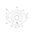
- FIG. 3 is an end view showing the rotation limiting device of the first example.
- FIG. 4 is an end view showing the first member and one intermediate member taken out from the rotation limiting device of the first example.
- FIG. 5 is an enlarged view of the X section in FIG.
- FIG. 6 is a cross-sectional view taken along YY line in FIG.
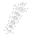
- FIG. 7 is an exploded perspective view showing the rotation limiting device of the first example.
- FIGS. 8(A) to 8(E) are schematic diagrams for explaining the operation of the rotation limiting device when the steering wheel is operated from the maximum right direction to the maximum left direction.
- FIGS. 9(A) to 9(E) are schematic diagrams for explaining the operation of the rotation limiting device when the steering wheel is operated from a state in which the steering wheel is operated to the maximum left to the maximum right to the maximum right.
- FIG. 10 is a sectional view showing a modification of the structure of the press-fit portion of the pin.
- FIG. 11 is a perspective view showing a second example of a rotation limiting device according to an embodiment of the present disclosure.
- FIG. 12 is a perspective view of the second example of the rotation limiting device viewed from a different angle from FIG. 11.
- FIG. 13 is an exploded perspective view showing a second example of the rotation limiting device.
- FIGS. 14(A) to 14(E) show the rotation limiting device of the third example of the embodiment of the present disclosure when the steering wheel is operated from the maximum right direction to the maximum left direction.
- FIG. 3 is a schematic diagram for explaining the operation of the rotation limiting device of FIG. 15(A) to 15(E) show the operation of the rotation limiting device of the third example when the steering wheel is operated from the left to the maximum to the right to the maximum. It is a schematic diagram for explanation.
- FIG. 16 is an end view of the first member taken out from the rotation limiting device of the third example and viewed from one side in the axial direction.
- FIG. 17 is a partially enlarged view of an intermediate member that constitutes a rotation limiting device according to a fourth example of an embodiment of the present disclosure.
- FIGS. 18(A) and 18(B) are partially enlarged views showing two other examples of how the elastic ring is attached.
- FIG. 19(A) is a partially enlarged cross-sectional view of an intermediate member constituting a rotation limiting device according to a fourth example of the embodiment of the present disclosure
- FIG. 19(B) is a partially enlarged sectional view of a substrate and pins constituting the intermediate member.
- FIG. 19C is an exploded cross-sectional view showing a state in which the substrate and the pin are combined.
- FIG. 20 is an exploded view showing a stopper unit with a conventional structure.
- FIGS. 1 to 10 A first example of an embodiment of the present disclosure will be described with reference to FIGS. 1 to 10.
- This example is an example in which a rotation limiting device 4 is incorporated into a steering unit 3 constituting a steering device 1 in order to limit the lock-to-lock rotation speed of a steering wheel 2 of a steer-by-wire type steering device 1.
- the longitudinal direction means the longitudinal direction of the vehicle.
- the steering device 1 includes a steering unit 3 having a steering wheel 2, a steering unit 6 that applies a steering angle to a pair of steered wheels 5, and a control unit (ECU) 7.
- the steering device 1 has a linkless structure in which a steering unit 3 and a steering unit 6 are not mechanically connected but electrically connected via a control unit 7.
- the steering unit 3 includes a steering column 8, a steering shaft 9, a reaction force applying device 10, and a rotation limiting device 4.
- the steering column 8 has a cylindrical shape and is supported with respect to the vehicle body.
- the steering shaft 9 is rotatably supported inside the steering column 8 in the radial direction.
- the steering wheel 2 is supported and fixed to the rear end of the steering shaft 9.
- the reaction force applying device 10 is connected to the front end of the steering shaft 9.
- the reaction force applying device 10 includes a reaction force applying motor and a speed reducer such as a worm speed reducer, and applies the output torque of the reaction force applying motor to the steering shaft 9 after increasing the output torque with the speed reducer.
- the rotation limiting device 4 is provided between the steering shaft 9 and a portion that does not rotate during use, and limits the lock-to-lock rotation speed of the steering wheel 2.
- the rotation limiting device 4 is provided between the front portion of the steering shaft 9 and the front end of the steering column 8, which does not rotate during use.
- the rotation limiting device 4 can be provided at any position between the steering shaft 9 and a fixed portion that does not rotate during use.
- the rotation limiting device 4 may be provided at a portion closer to the steering wheel 2, for example, between the rear portion of the steering shaft 9 and the rear end of the steering column 8.
- the rotation limiting device 4 may be provided between the front end of the steering shaft 9 and the housing of the reaction force applying device 10, which does not rotate during use. If the rotation limiting device 4 is disposed between the front end of the steering shaft 9 and the housing of the reaction force applying device 10, the rotation limiting device 4 can be attached and removed relatively easily.
- the steering unit 3 further includes sensors (not shown) such as a torque sensor and a steering angle sensor that measure the operation of the steering wheel 2 by the driver.
- sensors such as a torque sensor and a steering angle sensor that measure the operation of the steering wheel 2 by the driver.
- the steering unit 6 includes a gear housing 11 supported and fixed to the vehicle body, a linearly moving member (not shown), and a steering actuator 12 that linearly drives the linearly moving member.
- the linear motion member is composed of a rack shaft, a screw shaft, etc.
- the linear motion member is supported inside the gear housing 11 so as to be capable of linear movement in the axial direction, with its axial direction facing the width direction of the vehicle body.
- the base end portions of a pair of tie rods 13 are connected to both ends of the linear motion member in the axial direction via spherical joints (not shown), and the tip portions of the pair of tie rods 13 are connected to a pair of steered wheels. 5 is supported.
- the steering actuator 12 When the linear motion member is constituted by a rack shaft, the steering actuator 12 includes a pinion shaft that meshes with the rack shaft, a steering motor, and a speed reducer, and converts the output torque of the steering motor into the speed reducer. After increasing the amount, it is input to the pinion shaft, and the pinion shaft is rotationally driven to linearly move the rack shaft.
- the steering actuator 12 When the linear motion member is constituted by a screw shaft, the steering actuator 12 includes a nut supported around the screw shaft so as to be rotatable with respect to the screw shaft, a steering motor, and a speed reducer.
- the steering actuator 12 increases the output torque of the steering motor using a speed reducer, inputs the torque to a nut, and rotates the nut to linearly move the screw shaft.
- the feed screw mechanism that includes a screw shaft and a nut is a sliding screw type feed mechanism in which a male thread on the outer circumferential surface of the screw shaft and a female thread on the inner circumferential surface of the nut are directly screwed together.
- It can be configured by a screw mechanism, or it can be constructed by installing a plurality of balls between an inner ball screw groove provided on the outer circumferential surface of the screw shaft and an outer ball screw groove provided on the inner circumferential surface of the nut. It can also be configured by a ball screw type feed screw mechanism arranged so as to be freely rollable.
- the control unit 7 receives various signals indicating driving conditions, such as steering torque measured by a torque sensor, steering angle measured by a steering angle sensor, vehicle speed, yaw rate, and acceleration.
- the control unit 7 drives the steering actuator 12 included in the steering unit 6 based on various signals indicating driving conditions.
- the linearly moving member is displaced in the width direction of the vehicle body, the pair of tie rods 13 are pushed and pulled, and a steering angle is imparted to the pair of steered wheels 5.
- the rotation limiting device 4 of this example is provided between the front portion of the steering shaft 9 and the steering column 8, which does not rotate even when in use, and by limiting the amount of rotation of the steering shaft 9 to a predetermined value, 2. Limits the lock-to-lock rotation speed.
- the rotation restriction device 4 includes a first member 14, a second member 15, and at least one intermediate member 16a, 16b, and 16c.
- the rotation limiting device 4 can adjust the rotatable amount of the steering shaft 9 coupled and fixed to the second member 15 by changing the number of intermediate members 16a, 16b, and 16c. That is, as the number of intermediate members 16a, 16b, and 16c increases, the amount of rotation of the steering shaft 9 can be increased, whereas as the number of intermediate members 16a, 16b, and 16c decreases, the amount of rotation of the steering shaft 9 can be increased. The possible amount can be reduced.
- At least one intermediate member 16a, 16b, 16c is composed of three intermediate members 16a, 16b, 16c.
- the intermediate members 16a, 16b, and 16c have different symbols for convenience of explanation, but have the same shape.
- the second member 15 constitutes one member having a cylindrical portion
- the first member 14 constitutes the other member having a circular hole.
- the first member 14 has an end axial one-sided protrusion 17 that protrudes toward one axial side (left side in FIG. 6) at a position radially away from its central axis.
- the first member 14 includes a substrate 18 and pins 19.
- the substrate 18 is composed of a flat plate having a substantially rhombic end face shape when viewed from the axial direction.
- the substrate 18 has a circular hole 20 penetrating in the axial direction at the center thereof, and mounting holes 21 penetrating in the axial direction at both end portions in the long diagonal direction (left-right direction in FIG. 3).
- the substrate 18 has a press-fit hole 22 that penetrates in the axial direction at a portion away from the circular hole 20 on one side in the short diagonal direction (lower side in FIG. 3).
- the pin 19 has a cylindrical shape.
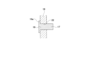
- the first member 14 is constructed by coupling and fixing the substrate 18 and the pin 19 by press-fitting the end of the pin 19 on the other axial direction (right side in FIG. 6) into the press-fit hole 22 of the substrate 18. ing. That is, in this example, the end axially one side protrusion 17 is constituted by one axially one side portion of the pin 19 that protrudes to one axial side than the axially one side surface of the substrate 18 .
- a pin flange 19a that protrudes radially outward is provided at the other end of the pin 19 in the axial direction, and the pin 19 is inserted into the press-fit hole 22 of the substrate 18 from the other axial direction.
- the first member 14 can also be formed by press-fitting.
- the pin 19 collides with the substrate 18 due to the collision between the end axially one side protrusion 17 of the first member 14 and the intermediate one side abutting surface 32 or the intermediate other side abutting surface 33 of the intermediate member 16c on the other axial side. Even if force is repeatedly applied to the pin 19 in the direction of causing it to fall, the pin 19 can be prevented from falling out of the press-fit hole 22.
- the first member 14 is configured such that the coupling bolts inserted through the respective mounting holes 21 of the base plate 18 are screwed into the column-side threaded holes opened on the front side surface of the steering column 8. It is supported and fixed to the steering column 8 which does not rotate even during use. That is, the rotation limiting device 4 of this example is incorporated into the steering device 1 with one axial side facing the front side of the vehicle and the other axial side facing the rear side of the vehicle.
- the second member 15 has an abutment surface 23 at one end of the end facing one side in the circumferential direction (the front side in the clockwise direction in FIG. 3) and the other end facing in the other side in the circumferential direction (the rear side in the clockwise direction in FIG. 3). It has an abutment surface 24 and is arranged coaxially with the first member 14 and capable of relative rotation with respect to the first member 14 .
- the second member 15 includes a cylindrical portion 25, a flange portion 26, and an end radial projection 27.
- the cylindrical portion 25 has an outer diameter slightly smaller than the inner diameter of the circular hole 20 of the first member 14. Further, the cylindrical portion 25 has a locking groove 28 over the entire circumference on the outer circumferential surface of the other end in the axial direction.
- the flange portion 26 protrudes from the outer peripheral surface of one end of the cylindrical portion 25 in the axial direction toward the outside in the radial direction over the entire circumference.
- the cylindrical portion 25 is externally fitted and fixed to the steering shaft 9 so as not to be relatively rotatable. Specifically, a female spline portion provided on the inner peripheral surface of the cylindrical portion 25 is spline-engaged with a male spline portion provided on the outer peripheral surface of the front portion of the steering shaft 9. Thereby, the second member 15 is supported and fixed to the steering shaft 9, which rotates as the steering wheel 2 is operated.
- the end radial protrusion 27 has a substantially fan-shaped end face shape when viewed from the axial direction, and protrudes radially outward from a portion of the flange portion 26 in the circumferential direction.
- the end radial protrusion 27 has an end abutment surface 23 on one side in the circumferential direction, and has an end abutment surface 24 on the other side in the circumferential direction.
- the one-side end abutting surface 23 and the other end abutting surface 24 are formed of partially cylindrical concave curved surfaces.
- each of the intermediate members 16a, 16b, and 16c includes a base 31, an intermediate radial protrusion 29, and an intermediate axial one-sided protrusion 30.
- the intermediate members 16a, 16b, and 16c are arranged between the first member 14 and the second member 15 in the axial direction, coaxially with the first member 14 and the second member 15, and arranged between the first member 14 and the second member 15. It is arranged so that it can be rotated.
- the base 31 has an intermediate circular hole 43 in the center that passes through it in the axial direction.
- the base portion 31 is configured in a cylindrical shape, and has an inner diameter slightly larger than the outer diameter of the cylindrical portion 25 of the second member 15, and an outer diameter that is approximately the same as the outer diameter of the flange portion 26. has.
- the intermediate radial protrusion 29 has a substantially fan-shaped end face shape when viewed from the axial direction, and protrudes radially outward from a portion of the base portion 31 in the circumferential direction.
- the intermediate radial protrusion 29 has an intermediate one-side abutment surface 32 on one side in the circumferential direction, and has an intermediate other-side abutment surface 33 on the other side in the circumferential direction.
- the intermediate one-side abutting surface 32 and the intermediate other-side abutting surface 33 are formed by partially cylindrical concave curved surfaces.
- the intermediate axial one-sided protrusion 30 has a cylindrical shape, and protrudes toward one axial side from the circumferential center position of one axial side surface of the intermediate radial protrusion 29.
- the rotation limiting device 4 of this example is constructed by combining a first member 14, a second member 15, and three intermediate members 16a, 16b, and 16c such that they can rotate relative to each other.
- the cylindrical portion 25 of the second member 15 is fitted into the intermediate circular holes 43 of the intermediate members 16a, 16b, and 16c and the circular hole 20 of the first member 14 so as to be relatively rotatable.
- a locking groove 28 formed in the outer circumferential surface of the end of the cylindrical portion 25 on the other axial side that protrudes further to the other axial side than the other axial side of the first member 14 is provided with a retaining ring in the form of an omitted ring. 34 is locked.
- the rotational resistance of the intermediate member and the other member relative to the cylindrical portion is preferably low.
- the outer peripheral surface of the cylindrical portion, the inner peripheral surface of the intermediate circular hole, and the inner peripheral surface of the circular hole can be lubricated with grease.
- At least one of the outer circumferential surface of the cylindrical portion, the inner circumferential surface of the intermediate circular hole, and the inner circumferential surface of the circular hole may be made of a low-friction material such as polytetrafluoroethylene resin, polyamide resin, or molybdenum disulfide. Can be configured.
- at least one of the outer circumferential surface of the cylindrical portion, the inner circumferential surface of the intermediate circular hole, and the inner circumferential surface of the circular hole may have a coating layer of a low-friction material.
- a radial rolling bearing or a radial sliding bearing can be arranged between the cylindrical part and the intermediate member and the other member.
- the end axially one side protrusion 17 of the first member 14 is in contact with the intermediate one side abutting surface 32 and the intermediate other side abutting surface 33 of the intermediate member 16c on the other axial side in the circumferential direction. to face.
- the intermediate axial one-side protrusion 30 of the intermediate member 16c on the other axial side faces in the circumferential direction the intermediate one-side abutting surface 32 and the intermediate other-side abutting surface 33 of the intermediate member 16b on the axially central side.
- the intermediate axial one-side protrusion 30 of the axially central intermediate member 16b circumferentially faces the intermediate one-side abutting surface 32 and the intermediate other-side abutting surface 33 of the axially one-sided intermediate member 16a. Further, the intermediate axial one-side protrusion 30 of the intermediate member 16a on one side in the axial direction faces the one end abutting surface 23 and the other end abutting surface 24 of the second member 15.
- the end axial one-sided protrusion 17 of the first member 14 and the intermediate radial protrusion 29 of the intermediate member 16c on the other axial side are connected to the intermediate axial one-sided protrusion 30 of the intermediate member 16c on the other axial side.
- the intermediate axial one-sided protrusion 30 of the intermediate member 16a and the end radial protrusion 27 of the second member 15 are arranged to overlap each other in the circumferential direction.
- the neutral position of the steering wheel 2 where the pair of steered wheels 5 face straight ahead can be adjusted by, for example, operating the steering shaft 9 to the maximum right or left. This can be done by operating the steering shaft 9 to the left or right by half of its rotatable amount.
- the method is not limited to this, and any method can be used.
- the outer diameter of the end axial one-sided protrusion 17 of the first member 14 and the outer diameter of the intermediate axial one-sided protrusion 30 of each intermediate member 16a, 16b, 16c are the same.
- the outer peripheral surface of the end axial one-sided projection 17 and the outer peripheral surface of the intermediate axial one-sided projection 30 are constituted by cylindrical surfaces having the same radius of curvature.
- the end axial one-sided protrusion 17 of the first member 14 and the intermediate axial one-sided protrusion 30 of the intermediate members 16a, 16b, and 16c are arranged at the same radial position. . Therefore, the circumferential width of the end axial one-sided protrusion 17 and the circumferential width of the intermediate axial one-sided protrusion 30 are the same.
- the end face shape of the end radial protrusion 27 of the second member 15 when viewed from the axial direction, and the end face shape of the intermediate radial protrusion 29 of each of the intermediate members 16a, 16b, and 16c when viewed from the axial direction. are the same as each other. That is, the radius of curvature of the one-side end abutting surface 23 and the other end abutting surface 24 is the same as the radius of curvature of the intermediate one-side abutting surface 32 and the other intermediate abutting surface 33.
- the end radial projection 27 of the second member 15 and the intermediate radial projection 29 of each intermediate member 16a, 16b, 16c are arranged at the same radial position. . Therefore, the circumferential width of the end radial projection 27 and the circumferential width of the intermediate radial projection 29 are the same.
- the angle ⁇ r formed by the contacting portions is not particularly limited as long as strength and rigidity can be ensured.
- the sum of the angle ⁇ a and the angle ⁇ r can be greater than or equal to 60 degrees and less than or equal to 120 degrees. In the illustrated example, the angle ⁇ a is 10 degrees, and the angle ⁇ r is about 80 degrees.
- the radius of curvature of the abutting surfaces 23 and 32 on one side and the radius of curvature of the abutting surfaces 24 and 33 on the other side are the radius of curvature of the outer circumferential surface of the end axial one-sided protrusion 17 and the intermediate axial one-sided protrusion 30.
- the radius of curvature of the outer circumferential surface of the The radius of curvature of the abutment surfaces 23 and 32 on one side and the abutment surfaces 24 and 33 on the other side are not particularly limited, but for example, from a surface that suppresses surface pressure during contact to a
- the radius of curvature of the outer peripheral surface of the one-sided projection 17 and the radius of curvature of the outer peripheral surface of the intermediate axial one-sided projection 30 can be set to 110% or more, and preferably 110% or more and 120% or less.
- the diameter D a of the first virtual circle centered on the central axis O of the rotation limiting device 4 and passing through the central axis C a of the axial protrusions 17 and 30 is the center of the rotation limiting device 4. It is made smaller than the diameter D r of a second virtual circle centered on the axis O and passing through the center of curvature of the abutment surfaces 23 and 32 on one side and the center of curvature C r of the abutment surfaces 24 and 33 on the other side. D a ⁇ D r ).
- FIGS. 8(A) to 9(E) show the end axial one-sided protrusion 17 of the first member 14, the end radial protrusion 27 of the second member 15, and the three intermediate members 16a, 16b, 16c.
- FIG. 3 is a diagram schematically showing the intermediate radial protrusion 29 and the intermediate axial one-sided protrusion 30 when viewed from the outside in the radial direction.
- one side in the circumferential direction is the front side in the counterclockwise direction as viewed from the driver seated in the driver's seat (as seen from the other side in the axial direction), and is E)
- the other side in the circumferential direction refers to the front side in the clockwise direction as viewed from the driver seated in the driver's seat, and refers to the upper side in FIGS. 8(A) to 9(E).
- the steering wheel 2 is turned as far as it can go from the right (clockwise as seen from the driver in the driver's seat, the other side in the circumferential direction) to the left (counterclockwise as seen from the driver in the driver's seat, circular).
- the rotation limiting device 4 When operating the rotation limiting device 4 to the maximum extent (on one side in the circumferential direction), the rotation limiting device 4 rotates as shown in FIGS. 8(A), 8(B), 8(C), 8(D), and 8(E). It operates as shown in the following order.
- the other end abutment surface 24 of the second member 15 touches one side of the intermediate member 16a in the axial direction. It is in contact with the protrusion 30.
- the other intermediate abutment surface 33 of the intermediate member 16a on one side in the axial direction is in contact with the intermediate protrusion 30 on one side in the axial direction of the intermediate member 16b in the center in the axial direction.
- the other intermediate abutment surface 33 of the axially central intermediate member 16b is in contact with the intermediate axial one-sided protrusion 30 of the axially other intermediate member 16c.
- the other intermediate abutting surface 33 of the intermediate member 16c on the other axial side is in contact with the axial protrusion 17 of the first member 14.
- the second member 15 is formed at an angle smaller than 360 degrees by the sum of the circumferential width ⁇ r of the end radial projection 27 and the circumferential width ⁇ a of the intermediate axial one-sided projection 30 , in this example.
- the end one side abutting surface 23 comes into contact with the intermediate axial side protrusion 30 of the intermediate member 16a on one side in the axial direction.
- the second member 15 and the intermediate member 16a on one side in the axial direction are arranged so that the circumferential width ⁇ r of the intermediate radial protrusion 29 of the intermediate member 16a on one side in the axial direction and the intermediate member 16b in the center in the axial direction are different from each other by 360 degrees.
- the intermediate member on one side in the axial direction is rotated counterclockwise by an angle that is smaller by the sum of the circumferential width ⁇ a of the intermediate axial one-sided protrusion 30, 270 degrees in this example, as shown in FIG.
- the second member 15, the intermediate member 16a on one side in the axial direction, and the intermediate member 16b in the center in the axial direction are arranged so that the circumferential direction width ⁇ r of the intermediate radial projection 29 of the intermediate member 16b in the center in the axial direction is greater than 360 degrees. and the circumferential width ⁇ a of the intermediate axial one-sided protrusion 30 of the intermediate member 16c on the other axial side.
- the intermediate one side abutment surface 32 of the intermediate member 16b at the axial center abuts the intermediate one side protrusion 30 in the axial direction of the intermediate member 16c at the other side in the axial direction.
- the second member 15 and the three intermediate members 16a, 16b, and 16c are arranged so that the circumferential width ⁇ r of the intermediate radial projection 29 of the intermediate member 16c on the other side in the axial direction than 360 degrees and the first member
- the intermediate member on the other side in the axial direction is rotated by an angle that is smaller by the sum of the circumferential direction width ⁇ a of the end portion 17 of the end portion 17 in the axial direction, 270 degrees in this example, as shown in FIG. 8(E)
- the intermediate one-side abutment surface 32 of the first member 16 c comes into contact with the end axial one-side protrusion 17 of the first member 14 .
- the intermediate member 16c on the other axial side is prevented from further rotating counterclockwise with respect to the first member 14.
- the intermediate member 16c on the other axial side is prevented from rotating counterclockwise
- the intermediate member 16b at the center in the axial direction is prevented from further rotating counterclockwise.
- the axially central intermediate member 16b is prevented from rotating counterclockwise
- the axially one intermediate member 16a is prevented from further rotating counterclockwise.
- the intermediate member 16a on one side in the axial direction is prevented from rotating counterclockwise
- the second member 15 is prevented from further rotating counterclockwise
- the steering shaft 9 and the steering shaft 9 are The supported and fixed steering wheel 2 is prevented from rotating further in the counterclockwise direction.
- the end one side abutment surface 23 of the second member 15 touches the intermediate axial one side protrusion of the intermediate member 16a on one axial side. It is in contact with 30.
- An intermediate one-side abutment surface 32 of the intermediate member 16a on one side in the axial direction is in contact with an intermediate one-side protrusion 30 in the intermediate axial direction of the intermediate member 16b in the axial center.
- the intermediate one-side abutment surface 32 of the intermediate member 16b at the axial center is in contact with the intermediate one-sided protrusion 30 of the intermediate member 16c on the other axial side.
- the intermediate one side abutment surface 32 of the intermediate member 16c on the other axial side is in contact with the axial protrusion 17 of the first member 14.
- the second member 15 is larger than 360 degrees by the sum of the circumferential width ⁇ r of the end radial projection 27 and the circumferential width ⁇ a of the intermediate axial one-sided projection 30 of the intermediate member 16 a on one axial side.
- the other end abutment surface 24 comes into contact with the intermediate axial one-sided protrusion 30 of the intermediate member 16a on one axial side, as shown in FIG. 9(B). .
- the second member 15 and the intermediate member 16a on one side in the axial direction are arranged so that the circumferential width ⁇ r of the intermediate radial protrusion 29 of the intermediate member 16a on one side in the axial direction and the intermediate member 16b in the center in the axial direction are different from each other by 360 degrees.
- the intermediate member 16a on one side in the axial direction is rotated clockwise by an angle that is smaller by the sum of the circumferential width ⁇ a of the intermediate axial one-sided protrusion 30, 270 degrees in this example, as shown in FIG. 9(C), the intermediate member 16a on one axial side
- the middle other side abutment surface 33 of 2 abuts on the middle axially one side protrusion 30 of the middle member 16b in the axially center.
- the second member 15, the intermediate member 16a on one side in the axial direction, and the intermediate member 16b in the center in the axial direction are arranged so that the circumferential direction width ⁇ r of the intermediate radial projection 29 of the intermediate member 16b in the center in the axial direction is greater than 360 degrees. and the circumferential width ⁇ a of the intermediate axial one-sided protrusion 30 of the intermediate member 16c on the other axial side.
- the other intermediate abutment surface 33 of the axially central intermediate member 16b abuts the intermediate axial one-side protrusion 30 of the axially other intermediate member 16c.
- the second member 15 and the three intermediate members 16a, 16b, and 16c are arranged so that the circumferential width ⁇ r of the intermediate radial projection 29 of the intermediate member 16c on the other side in the axial direction than 360 degrees and the first member
- the intermediate member 16c on the other axial side is rotated by an angle smaller than the sum of the circumferential width ⁇ a of the end portion 17 of the end portion 14, 270 degrees in this example, as shown in FIG. 9(E)
- the intermediate member 16c on the other axial side The middle other side abutment surface 33 abuts against the end axial one side protrusion 17 of the first member 14 .
- the intermediate member 16c on the other axial side is prevented from further rotating clockwise with respect to the first member 14.
- the intermediate member 16c on the other axial side is prevented from rotating clockwise
- the intermediate member 16b at the axial center is prevented from further rotating clockwise.
- the axially central intermediate member 16b is prevented from rotating clockwise
- the axially one intermediate member 16a is prevented from further rotating clockwise.
- the second member 15 is prevented from further clockwise rotation, and is supported and fixed to the steering shaft 9 and the steering shaft 9.
- the steering wheel 2 is prevented from rotating further in the clockwise direction.
- the intermediate member 16a on one side in the axial direction and the intermediate member in the center in the axial direction 16b and/or the intermediate member 16c on the other axial side may rotate so as to be rotated by the second member 15.
- the operation order of the rotation limiting device 4 may be different from the examples shown in FIGS. 8(A) to 8(E) and FIGS. 9(A) to 9(E).
- the circumferential width of the end axial one-sided projection 17 is the same as the circumferential width of the intermediate axial one-sided projection 30, and the circumferential width of the end radial projection 27 is the same.
- the circumferential width of the intermediate radial protrusions 29 is the same, the more the number of intermediate members 16a, 16b, 16c is increased, the more the steering shaft 9 can rotate by 360 degrees than the axial protrusions 17, 30.
- the angle can be increased by the sum of the circumferential width ⁇ a and the circumferential width ⁇ r of the radial protrusions 27 and 29, which is 270 degrees in this example.
- the rotatable amount of the steering shaft 9 is increased by increasing the circumferential width of the axial protrusions 17, 30 and the radial protrusions 27, 29 from 360 degrees.
- the angle can be reduced by the sum of the circumferential width, 270 degrees in this example.
- the sum of the circumferential width ⁇ a of the axial protrusions 17 and 30 and the circumferential width ⁇ r of the radial protrusions 27 and 29 is the sum of the circumferential width ⁇ a of the axial protrusions 17 and 30 and the circumferential width ⁇ r of the radial protrusions 27 and 29.
- the rotatable amount of the steering shaft 9 can be adjusted by changing the number of intermediate members 16a, 16b, and 16c.
- the degree of freedom in setting the rotatable amount can be improved.
- the intermediate members 16a, 16b, and 16c all have the same shape.
- the rotatable amount of the rotary member can be adjusted by increasing or decreasing the number of intermediate members having the same shape. Therefore, according to the rotation limiting device of the present disclosure, it is possible to prevent unnecessary increases in manufacturing costs, management costs, and assembly costs of parts, and it is possible to suppress increases in manufacturing costs of the rotation limiting device.
- the circumferential width of the end axial one-sided protrusion 17 of the first member 14 is the same as the circumferential width of the intermediate axial one-sided protrusion 30 of all intermediate members 16a, 16b, and 16c.
- the circumferential width of the end radial projection 27 of the second member 15 is the same as the circumferential width of the intermediate radial projection 29 of all intermediate members 16a, 16b, and 16c.
- the circumferential width of the end axial one-sided protrusion of the first member and the circumferential width of the intermediate axial one-sided protrusion of the at least one intermediate member may be made different from each other. can.
- the circumferential width of the end radial projection of the second member and the circumferential width of the at least one intermediate radial projection may be different from each other.
- the rotatable amount of the steering shaft 9 is adjusted by making the circumferential width of the end radial projection 27 different from the circumferential width of the intermediate radial projection 29. You can also do that.
- the circumferential width of all the axial protrusions 17 and 30 is 10 degrees, and the circumferential width of all the radial protrusions 27 and 29 is 80 degrees, so the steering shaft 9 can be rotated.
- the amount is 1080 degrees.
- the circumferential width of all the axial protrusions 17, 30 is 10 degrees
- the circumferential width of the intermediate radial protrusions 29 of the three intermediate members 16a, 16b, 16c is 80 degrees
- the circumferential width of the end radial projection 27 is approximately 70 degrees, the amount of rotation of the steering shaft 9 can be 1090 degrees.
- the end axial one-sided protrusion 17 of the first member 14 and the intermediate axial one-sided protrusion 30 of each of the intermediate members 16a, 16b, 16c in order to stabilize the destructive load that would make the rotation limiting device 4 unusable, the end axial one-sided protrusion 17 of the first member 14 and the intermediate axial one-sided protrusion 30 of each of the intermediate members 16a, 16b, 16c.
- the circumferential width of any one of the axial protrusions may be smaller than the circumferential width of the remaining axial protrusions.
- the intermediate axial one-sided projections 30 of each of the intermediate members 16a, 16b, and 16c protrude only to one side in the axial direction. Therefore, compared to the case where the intermediate member has protrusions that respectively protrude toward both sides in the axial direction, the structure can be simplified and manufacturing costs can be reduced.
- each of the intermediate members 16a, 16b, and 16c can be made integrally by press working.
- each of the intermediate members 16a, 16b, and 16c can be made by supporting and fixing a cylindrical pin to a flat member having the base portion 31 and the intermediate radial projection 29.
- the flat member and the pin can be made of the same material, or can be made of different materials.
- the flat member is made of a metal material and the pin is made of synthetic resin, it is possible to ensure the strength and rigidity of the intermediate member and reduce the collision noise that occurs when the rotation limiting device is used. .
- the intermediate member has protrusions that protrude toward both sides in the axial direction, it is difficult to make it in one piece because it can be pressed, and it has to be made by cutting, which may increase manufacturing costs. . Furthermore, when a flat member and a pin are combined, it is necessary to precisely control the amount of press-fitting of the pin, which may make the assembly work troublesome.
- each of the intermediate members 16a, 16b, and 16c is constructed by coupling and fixing a flat member and a pin
- the other axial side of the pin is similar to the modification of the first member 14 shown in FIG.
- a pin flange may be provided at the end.
- the three intermediate members 16a, 16b, 16c and the first member 14 are held between the flange portion 26 of the second member 15 and the retaining ring 34 in the axial direction. . Therefore, even before the first member 14 is supported and fixed to the steering column 8 and the second member 15 is coupled and fixed to the steering shaft 9, the rotation limiting device 4 is assembled in advance (assembled into an assembly). )be able to. Therefore, the handling of the rotation limiting device 4 can be improved.
- the side surfaces on both sides in the circumferential direction of the first rotary projection 104, the side surfaces on both sides in the circumferential direction of the fixed projection 105, and the side surfaces on both sides in the circumferential direction of the second rotary projection 107. are inclined with respect to the axial direction when viewed from the outside in the radial direction. Therefore, when the first rotating member 101 rotates, the first rotating member 101 and the second rotating member 103 and/or the second rotating member 103 and the housing 102 are separated from each other in the axial direction. The force of is added. Therefore, it is necessary to make the axial connection strength of the first rotating member 101 to the steering shaft and the axial connection strength of the housing 102 to the vehicle body sufficiently high.
- Each of the one-side abutting surface 32 and the intermediate other-side abutting surface 33 extends linearly in the axial direction when viewed from the radial direction. Therefore, even when the first member 14 rotates with the rotation of the steering shaft 9, there is a gap between the second member 15 and the intermediate member 16a on one side in the axial direction, and between the intermediate member 16c on the other side in the axial direction and the first member. 14 and between adjacent intermediate members 16a, 16b, and 16c.
- the diameter D a of the first virtual circle is smaller than the diameter D r of the second virtual circle (D a ⁇ D r ). Therefore, when the end axial one side protrusion 17 or the intermediate axial one side protrusion 30 collides with the intermediate one side abutting surface 32 or the intermediate other side abutting surface 33, the intermediate members 16a, 16b, 16c , a force F (see FIG. 5) may be applied in a direction to press the intermediate radial protrusion 29 radially inward.
- the portion that is pressed radially inward due to the collision between the axial protrusions 17, 30 and the intermediate one-side abutting surface 32 or the intermediate other-side abutting surface 33 is defined as a portion having a large radial thickness. This makes it easy to ensure the strength of the intermediate members 16a, 16b, and 16c.
- the diameter of the first imaginary circle may be the same as the diameter of the second imaginary circle, or may be made larger than the diameter of the second imaginary circle. You can also do it.
- the three intermediate members 16a, 16b, 16c and the first member 14 are fitted onto the cylindrical portion 25 of the second member 15 so as to be able to rotate relative to each other without wobbling. . That is, in this example, coaxiality between the first member 14 and the second member 15 is ensured by the fitting portion between the circular hole 20 of the first member 14 and the cylindrical portion 25 of the second member 15.
- the fixed portion between the first member 14 and the steering column 8 positions the first member 14 in the radial direction with respect to the steering column 8
- the fixed portion between the second member 15 and the steering shaft 9 positions the steering shaft. If the coaxiality of the first member 14 and the second member 15 can be ensured by positioning the second member 15 in the radial direction with respect to the circular hole 20 of the first member 14 and the cylinder of the second member 15,
- the portion 25 may also be a loose fit with looseness. Thereby, the rotational resistance of the steering shaft 9 can be made substantially constant.
- the first member 14 is supported and fixed to the steering column 8, which does not rotate during use
- the second member 15 is supported and fixed to the steering shaft 9, which rotates during use.
- the second member may be supported and fixed to a fixed member that does not rotate during use
- the first member may be supported and fixed to a fixed member that rotates during use.
- the materials constituting the first member, the second member, and the intermediate member are not particularly limited as long as they can rotate (slide) relative to each other; for example, they may be composed of synthetic resin or metal material. be able to.
- the first member, the second member, and the intermediate member can be configured as a whole, or can be configured by combining a plurality of parts.
- the substrate and pins that make up the first member can be made of the same material, or can be made of different materials.
- the substrate is made of a metal material and the pin is made of a synthetic resin, it is possible to ensure the strength and rigidity of the first member and reduce the collision noise generated when the rotation limiting device is used.
- the rotation limiting device 4 is incorporated into the steering unit 3 that constitutes the steer-by-wire type steering device 1, but the rotation limiting device of the present disclosure is limited to the steer-by-wire type steering device.
- it can be incorporated and used to limit the rotatable amount of a rotating member of any rotary mechanical device, including a steering device in which a steering unit and a steering unit are mechanically connected.
- the flange portion 26 and the end radial projection 27 of the second member 15, and the intermediate members 16a, 16b, and 16c are It is also possible to provide a cover that covers from the outside.
- the cover can be provided so as to protrude from one side surface of the substrate 18 of the first member 14 in the axial direction toward one side in the axial direction.
- the rotation limiting device 4a of this example includes a first member 14a, a second member 15a, and three intermediate members 16a, 16b, and 16c.
- the first member 14a has an end axial one-side protrusion 17a that projects toward one side in the axial direction (the right side in FIGS. 11 to 13) at a position radially away from its central axis.
- the first member 14a includes a cylindrical portion 35, a flange portion 36, a radial protrusion 37, and an end axial one-sided protrusion 17a.
- the cylindrical portion 35 has a locking groove 38 on the outer peripheral surface of one end in the axial direction over the entire circumference.
- the flange portion 36 protrudes radially outward from the outer peripheral surface of the end of the cylindrical portion 35 on the other axial side (the left side in FIGS. 11 to 13) over the entire circumference.
- the radial protrusion 37 has a substantially fan-shaped end face shape when viewed from the axial direction, and protrudes radially outward from a portion of the flange portion 36 in the circumferential direction.
- the end axially one side protrusion 17a has a cylindrical shape and protrudes from the circumferential center position of the radial protrusion 37 toward one side in the axial direction.
- the second member 15a has an end abutment surface 23a facing one side in the circumferential direction and an end abutment surface 24a on the other side facing the other side in the circumferential direction, and is coaxial with the first member 14a. , are arranged so as to be rotatable relative to the first member 14a.
- the second member 15a has a substantially rhombic end face shape when viewed from the axial direction.
- the second member 15a has a circular hole 39 penetrating in the axial direction in the center, and has mounting holes 40 penetrating in the axial direction at both ends in the long diagonal direction (left-right direction in FIG. 3).
- the second member 15a has a groove 41 around the circular hole 39 that is open at least on the other side in the axial direction.
- the groove portion 41 is constituted by a through hole that passes through the second member 15a in the axial direction.
- the groove portion can also be configured as a groove that opens only on the other axial side surface of the second member.
- the second member 15a of this example has an end one side abutment surface 23a on a surface facing one side in the circumferential direction among the inner surfaces of the groove portion 41, and has an end abutment surface 23a on one side of the inner surface of the groove portion 41 in the circumferential direction.
- the other end abutting surface 24a is provided on the surface facing the side.
- the rotation limiting device 4a is constructed by combining a first member 14a, a second member 15a, and three intermediate members 16a, 16b, and 16c such that they can rotate relative to each other.
- the cylindrical portion 35 of the first member 14a is fitted into the circular hole 39 of the second member 15a and the intermediate circular holes 43 of the three intermediate members 16a, 16b, and 16c so as to be relatively rotatable.
- a retaining ring 42 in the form of a partially circular ring is provided in a locking groove 38 formed on the outer circumferential surface of one end in the axial direction that protrudes to one side in the axial direction from the one side surface in the axial direction of the second member 15a. It is locked.
- the end axially one side protrusion 17a of the first member 14a is in contact with the intermediate one side abutting surface 32 and the intermediate other side abutting surface 33 of the intermediate member 16a on the other axial side in the circumferential direction. to face.
- the intermediate axial one-side protrusion 30 of the intermediate member 16a on the other axial side faces in the circumferential direction the intermediate one-side abutting surface 32 and the intermediate other-side abutting surface 33 of the intermediate member 16b on the axially central side.
- the intermediate axial one-side protrusion 30 of the axially central intermediate member 16b faces the intermediate one-side abutting surface 32 and the intermediate other-side abutting surface 33 of the axially one-sided intermediate member 16c in the circumferential direction. Further, the intermediate axial one-side protrusion 30 of the intermediate member 16c on one side in the axial direction faces the one end abutting surface 23a and the other end abutting surface 24a of the second member 15a.
- the end axially one side protrusion 17a of the first member 14a and the intermediate radial protrusion 29 of the intermediate member 16a on the other axial side are connected to the intermediate axially one side protrusion 30 of the intermediate member 16a on the other axial side.
- the intermediate radial protrusion 29 of the axially central intermediate member 16b, the intermediate axial one-sided protrusion 30 of the axially central intermediate member 16b, and the intermediate radial protrusion 29 of the axially one-sided intermediate member 16c are each circumferentially
- the intermediate axial one-side protrusion 30 of the intermediate member 16c on one side in the axial direction, which is arranged to overlap in the direction, is arranged inside the groove portion 41 of the second member 15a.
- the second member 15a forms an abutment surface 23a on one end and an abutment surface 24a on the other end by providing a groove 41 in the plate material. Therefore, it is easy to reduce the weight of the rotation limiting device 4a.
- the shape of the circumferentially intermediate portion of the groove portion 41 sufficient accuracy can be ensured at both ends in the circumferential direction provided with the abutment surface 23a on one side of the end and the abutment surface 24a on the other side of the end. Further, as long as interference with the axial protrusion 30 of the intermediate member 16c on one side in the axial direction can be prevented, any shape can be used.
- a cover may be provided to cover the flange portion 36 and radial protrusion 37 of the first member 14a and the respective intermediate members 16a, 16b, and 16c from the outside in the radial direction.
- the cover can be provided so as to protrude from the other axial side of the second member 15a toward the other axial side.
- the rotation restriction device 4a includes a first member 14b, a second member 15b, and a plurality of intermediate members 16d, 16e, and 16f.
- the plurality of intermediate members 16d, 16e, and 16f are composed of three intermediate members 16d, 16e, and 16f.
- the remaining intermediate members 16d, 16e, and 16f include an intermediate radial protrusion 29 that protrudes radially outward;
- an intermediate shaft protrudes from the other axial side surface of the intermediate radial protrusion 29 toward the other axial side. It has a protrusion 44 on the other side.
- the intermediate member 16f disposed on the other side in the axial direction also has an intermediate radial protrusion 29 protruding radially outward, and a radial protrusion 29 extending from one axial side of the intermediate radial protrusion 29 to one axial side.
- the intermediate axial one side protrusion 30a that protrudes toward the intermediate axial direction
- all the intermediate members 16d, 16e, and 16f have the intermediate radial protrusion 29, the intermediate axial one-sided protrusion 30a, and the intermediate axial other-sided protrusion 44.
- the intermediate members 16d, 16e, and 16f have the same shape. Further, each of the intermediate members 16d, 16e, and 16f has a shape that is symmetrical with respect to the axial direction, and a shape that is symmetrical with respect to a virtual plane that includes the central axis and passes through the circumferential center position of the intermediate radial projection 29. has.
- the intermediate axial one side protrusion 30 a projects toward one side in the axial direction from the circumferential center position of one axial side surface of the intermediate radial protrusion 29 , and the intermediate axial other side protrusion 44 protrudes from the circumferential center position of one axial side surface of the intermediate radial protrusion 29 It protrudes toward the other axial side from the circumferential center position of the other axial side. That is, the protrusion 30a on one side in the intermediate axis direction and the protrusion 44 on the other side in the intermediate axis direction are coaxially arranged.
- the second member 15b protrudes toward the other side in the axial direction at a position deviated from the central axis in the radial direction, and the intermediate one side abutting surface 32 and the intermediate other side abutting surface of the intermediate member 16d disposed on the furthest one side in the axial direction It has a protrusion 45 on the other side in the axial direction of the end portion that faces the contact surface 33 in the circumferential direction.
- the end axially other side protrusion 45 protrudes from the circumferential center position of the axially other side surface of the end radial protrusion 27 toward the axially other side.
- the first member 14b has an intermediate axially other-side protrusion 44 of the intermediate member 16f disposed on the furthest axially other side, and the first member 14b has the axially other-sided protrusion 44 disposed on the most axially other side with respect to the first member 14b. It has a thinned portion 46 for allowing relative rotation of the intermediate member 16f disposed in the middle member 16f.
- the first member 14b is constructed by coupling and fixing a substrate 18a and a pin 19.
- the substrate 18a further includes a thinned portion 46.
- the thinned portion 46 is constituted by a through hole that axially penetrates a portion of the substrate 18a around the circular hole 20 and circumferentially removed from the press-fit hole 22.
- an end one side abutment surface 47 is provided on a surface facing one side in the circumferential direction of the inner surface of the thinned part 46, and the other side in the circumferential direction of the inner surface of the thinned part 46 is provided.
- the other end abutting surface 48 is provided on the surface facing.
- the other end of the pin 19 in the axial direction is press-fitted into the press-fit hole 22 .
- the end axially one side protrusion 17 is constituted by an axially one side portion of the pin 19 that protrudes to one side in the axial direction from one side surface in the axial direction of the substrate 18a.
- Each of the end axially one side protrusion 17, the end axially other side protrusion 45, the intermediate axially one side protrusion 30a, and the intermediate axially other side protrusion 44 has a thickness that is half the axial thickness of the intermediate radial protrusion 29. It has the following axial dimensions:
- the axial dimension of the end axially one side protrusion 17, the axial dimension of the end axially other side protrusion 45, the axial dimension of the intermediate axially one side protrusion 30a and the intermediate axially other side protrusion 44, are the same.
- the first member 14b and the three intermediate members 16d, 16e, and 16f are configured to be relatively rotatable in the cylindrical portion 25 (see FIGS. 6 and 7) of the second member 15b. It is fitted on the outside without any sag.
- the cylindrical portion 25 of the second member 15b is inserted through the circular hole 20 of the first member 14b and the intermediate circular holes 43 of the three intermediate members 16d, 16e, and 16f.
- a retaining ring 42 secured to one end of the cylindrical portion 35 in the axial direction prevents the first member 14b and the intermediate members 16d, 16e, and 16f from being displaced in the axial direction with respect to the second member 15b.
- the end axially one side protrusion 17a of the first member 14b is in contact with the axially other side portion of the intermediate one side abutment surface 32 of the intermediate member 16f on the other axial side and the intermediate other side abutment. It faces the other axial portion of the surface 33 in the circumferential direction.
- the intermediate axially other side protrusion 44 of the intermediate member 16f on the other axially side is arranged inside the thinned part 46 of the first member 14b, and has an end abutment surface 47 on one side and an end abutment surface 48 on the other side. Opposing in the circumferential direction. Further, the intermediate axial one side protrusion 30 of the intermediate member 16f on the other axial side is connected to the axially other side portion of the intermediate one side abutting surface 32 of the intermediate member 16e on the axially central side and the axial direction of the intermediate other side abutting surface 33. It faces the other side part in the circumferential direction.
- the intermediate axial other side protrusion 44 of the intermediate member 16e at the axial center is located at the axially one side portion of the intermediate one side abutting surface 32 and the axially one side portion of the intermediate other side abutting surface 33 of the intermediate member 16f at the axially other side. and facing in the circumferential direction.
- the intermediate axial one side protrusion 30 of the intermediate member 16f at the axial center is connected to the other axially other side portion of the intermediate one side abutting surface 32 of the intermediate member 16d on one side in the axial direction and the axially other side portion of the intermediate other side abutting surface 33. It faces the side portion in the circumferential direction.
- the intermediate axially other side protrusion 44 of the intermediate member 16d on one side in the axial direction is connected to the axially one side portion of the intermediate one side abutting surface 32 and the axially one side portion of the intermediate other side abutting surface 33 of the axially central intermediate member 16e. Opposing in the circumferential direction. Further, the intermediate axial one-side protrusion 30 of the intermediate member 16d on one side in the axial direction faces the one end abutting surface 23 and the other end abutting surface 24 of the second member 15b.
- the other end axially protruding portion 45 of the second member 15b is circumferentially connected to one axially one side portion of the intermediate one side abutting surface 32 of the intermediate member 16d on one side in the axial direction and the axially one side portion of the intermediate other side abutting surface 33. opposite direction.
- the rotation limiting device 4b of this example When the steering wheel 2 (see FIG. 1) is operated from the maximum right direction to the maximum left direction, the rotation limiting device 4b of this example operates as shown in FIGS. 14(A), 14(B), and 14. The operation is performed as shown in the order of (C), FIG. 14(D), and FIG. 14(E). Further, when the steering wheel 2 is operated from the left to the maximum to the right to the maximum, the rotation restricting device 4b of this example operates as shown in FIGS. 15(A), 15(B), and 15(C). , FIG. 15(D), and FIG. 15(E).
- the rotation restricting device 4b of this example members adjacent to each other in the axial direction, that is, the first member 14b and the intermediate member 16f on the other axial side, the intermediate member 16f on the other axial side and the intermediate member 16e in the axial center,
- the central intermediate member 16e and the intermediate member 16d on one side in the axial direction, and the intermediate member 16d on one side in the axial direction and the second member 15d each abut at two positions in the circumferential direction. Therefore, the circumferential force applied to each member can be effectively dispersed. Further, even if some of the protrusions are damaged, the function of limiting the lock-to-lock rotation speed can be maintained. That is, redundancy of the rotation limiting device 4b can be ensured.
- the intermediate axially other side protrusion of the intermediate member disposed on the furthest other side in the axial direction may be omitted.
- the thinned portion of the first member can be omitted.
- FIGS. 17 to 18(B) A fourth example of the embodiment of the present disclosure will be described using FIGS. 17 to 18(B).
- the basic configuration of the rotation limiting device of this example is not limited to this, but the structure of the first example, the second example, or the third example can be adopted.
- the rotation limiting device of this example is characterized in that it includes an annular elastic ring 49 that is fitted onto the intermediate axial one-sided protrusion 30 of the intermediate member 16g.
- the elastic ring 49 may be an O-ring having a circular cross-sectional shape.
- the elastic ring 49 is fitted onto the axially intermediate portion of the intermediate axially one-sided protrusion 30 .
- the external fitting position, number, cross-sectional shape, etc. of the elastic rings 49 are not particularly limited.
- an elastic ring 49 may be fitted onto the other axial end of the intermediate axial protrusion 30, or as shown in FIG. 18(B), two The elastic ring 49 can be externally fitted onto the intermediate axial one-sided protrusion 30.
- a locking groove for locking the elastic ring may be formed on the outer circumferential surface of the intermediate axial one-sided protrusion.
- the intermediate axial one-side protrusion 30 of the intermediate member 16g is connected to the intermediate one-side abutting surface 32 or the intermediate other-side abutting surface 33 of the intermediate member adjacent to one side in the axial direction, or the end of the second member 15. It is possible to suppress the collision noise when the end portion collides with the abutment surface 23 on one side or the abutment surface 24 on the other side of the end portion.
- an elastic ring can be fitted onto the end axial one-sided protrusion in addition to or instead of the intermediate axial one-sided protrusion. Furthermore, when the intermediate member includes a protrusion on the other side in the intermediate axis direction, an elastic ring can be externally fitted onto the protrusion on the other side in the intermediate axis direction.
- the intermediate member 16h includes an intermediate radial protrusion 29a that protrudes radially outward, and an intermediate axial protrusion 30a that protrudes from one axial side of the intermediate radial protrusion 29a toward one axial side. and an intermediate axial other side protrusion 44 that protrudes toward the other axial side from the other axial side surface of the intermediate radial protrusion 29a.
- An elastic ring 49 is fitted onto the other axial end of the intermediate axial one-side projection 30a and the axial one end of the intermediate axial other-side projection 44.
- the intermediate member 16h is constructed by coupling and fixing a substrate 50 and a pin 51.
- the intermediate radial protrusion 29a is configured to protrude radially outward from a circumferential portion of the base portion 31 of the substrate 50, and has a through hole 52 that axially passes through the circumferential center position.
- the protrusion 30 a on one side in the intermediate axial direction and the protrusion 44 on the other side in the intermediate axial direction are constructed by inserting the pin 51 into the through hole 52 .
- the pin 51 has a cylindrical shape and has locking grooves 53 at two axially intermediate portions over the entire circumference. A portion of the pin 51 between the two locking grooves 53 is fitted into the through hole without play, and an elastic ring 49 is locked in each of the locking grooves 53. This makes it impossible for the pin 51 to be displaced relative to the substrate 50 in the axial direction.
- Steering device 2 Steering wheel 3 Steering unit 4, 4a, 4b Rotation limiting device 5 Steering wheel 6 Steering unit 7 Control unit 8 Steering column 9 Steering shaft 10
- Reaction force applying device 11 Gear housing 12
- Steering actuator 13 Tie rod 14, 14a First member 15, 15a Second member 16a, 16b, 16c, 16d, 16e, 16f, 16g, 16h Intermediate member 17, 17a End axial protrusion 18 Board 19 Pin 19a Pin flange 20
- Circular hole 21 Mounting hole 22 Press-fit hole 23 Abutment surface on one side of the end 24 Abutment surface on the other end of the end 25 Cylindrical portion 26 Flange portion 27 End radial projection 28 Locking groove 29 Intermediate radial projection 30, 30a Intermediate axial one-side projection 31 Base 32 Intermediate One side abutting surface 33 Middle other side abutting surface 34 Retaining ring 35 Cylindrical part 36 Flange part 37 Radial projection 38 Locking groove 39 Circular hole 40 Mounting hole 41 Gro
Landscapes
- Engineering & Computer Science (AREA)
- Chemical & Material Sciences (AREA)
- Combustion & Propulsion (AREA)
- Transportation (AREA)
- Mechanical Engineering (AREA)
- Power Steering Mechanism (AREA)
Priority Applications (3)
| Application Number | Priority Date | Filing Date | Title |
|---|---|---|---|
| EP23852405.2A EP4570622A1 (en) | 2022-08-10 | 2023-07-28 | Rotation limiting device and steering device |
| JP2024540383A JP7777690B2 (ja) | 2022-08-10 | 2023-07-28 | 回転制限装置およびステアリング装置 |
| CN202380058239.1A CN119654272A (zh) | 2022-08-10 | 2023-07-28 | 旋转限制装置以及转向装置 |
Applications Claiming Priority (2)
| Application Number | Priority Date | Filing Date | Title |
|---|---|---|---|
| JP2022127888 | 2022-08-10 | ||
| JP2022-127888 | 2022-08-10 |
Publications (1)
| Publication Number | Publication Date |
|---|---|
| WO2024034432A1 true WO2024034432A1 (ja) | 2024-02-15 |
Family
ID=89851606
Family Applications (1)
| Application Number | Title | Priority Date | Filing Date |
|---|---|---|---|
| PCT/JP2023/027737 Ceased WO2024034432A1 (ja) | 2022-08-10 | 2023-07-28 | 回転制限装置およびステアリング装置 |
Country Status (4)
| Country | Link |
|---|---|
| EP (1) | EP4570622A1 (https=) |
| JP (1) | JP7777690B2 (https=) |
| CN (1) | CN119654272A (https=) |
| WO (1) | WO2024034432A1 (https=) |
Citations (6)
| Publication number | Priority date | Publication date | Assignee | Title |
|---|---|---|---|---|
| JP2000016316A (ja) * | 1998-06-30 | 2000-01-18 | Koyo Seiko Co Ltd | 車両用操舵装置 |
| JP2009280073A (ja) * | 2008-05-22 | 2009-12-03 | Honda Motor Co Ltd | 電動パワーステアリング装置 |
| JP2012166311A (ja) * | 2011-02-15 | 2012-09-06 | Mitsubishi Electric Corp | 回転リミット装置の消音装置 |
| JP2013193676A (ja) * | 2012-03-22 | 2013-09-30 | Jtekt Corp | 車両用操舵装置 |
| JP2020069844A (ja) | 2018-10-30 | 2020-05-07 | 株式会社ジェイテクト | 車両用操舵装置 |
| US20210024122A1 (en) * | 2019-07-25 | 2021-01-28 | Zf Automotive Germany Gmbh | Rotation limiting means, steering system, and method for limiting a rotational movement in a steering system |
-
2023
- 2023-07-28 WO PCT/JP2023/027737 patent/WO2024034432A1/ja not_active Ceased
- 2023-07-28 CN CN202380058239.1A patent/CN119654272A/zh active Pending
- 2023-07-28 EP EP23852405.2A patent/EP4570622A1/en active Pending
- 2023-07-28 JP JP2024540383A patent/JP7777690B2/ja active Active
Patent Citations (6)
| Publication number | Priority date | Publication date | Assignee | Title |
|---|---|---|---|---|
| JP2000016316A (ja) * | 1998-06-30 | 2000-01-18 | Koyo Seiko Co Ltd | 車両用操舵装置 |
| JP2009280073A (ja) * | 2008-05-22 | 2009-12-03 | Honda Motor Co Ltd | 電動パワーステアリング装置 |
| JP2012166311A (ja) * | 2011-02-15 | 2012-09-06 | Mitsubishi Electric Corp | 回転リミット装置の消音装置 |
| JP2013193676A (ja) * | 2012-03-22 | 2013-09-30 | Jtekt Corp | 車両用操舵装置 |
| JP2020069844A (ja) | 2018-10-30 | 2020-05-07 | 株式会社ジェイテクト | 車両用操舵装置 |
| US20210024122A1 (en) * | 2019-07-25 | 2021-01-28 | Zf Automotive Germany Gmbh | Rotation limiting means, steering system, and method for limiting a rotational movement in a steering system |
Also Published As
| Publication number | Publication date |
|---|---|
| JPWO2024034432A1 (https=) | 2024-02-15 |
| EP4570622A1 (en) | 2025-06-18 |
| JP7777690B2 (ja) | 2025-11-28 |
| CN119654272A (zh) | 2025-03-18 |
Similar Documents
| Publication | Publication Date | Title |
|---|---|---|
| US11260897B2 (en) | Steer-by-wire steering device and vehicle | |
| US8146705B2 (en) | Oscillating gear device, transmission ratio variable mechanism, and motor vehicle steering system | |
| JP7118673B2 (ja) | ステアリング装置 | |
| EP1714851B1 (en) | Electric power steering device | |
| JP2000043739A (ja) | 電動式舵取装置 | |
| CN114423668B (zh) | 线控转向式转向装置 | |
| JP2008254495A (ja) | 電動パワーステアリング装置 | |
| US20090139356A1 (en) | Variable ratio steering apparatus | |
| JP4464955B2 (ja) | 伸縮アクチュエータ | |
| JP2006151352A (ja) | ステアリング装置 | |
| US6374693B1 (en) | Variable steering ratio steering system | |
| JP2001322554A (ja) | 電動式舵取装置 | |
| WO2024034432A1 (ja) | 回転制限装置およびステアリング装置 | |
| WO2023149110A1 (ja) | 回転制限装置およびステアリング装置 | |
| US12304574B1 (en) | Rotation limiting device, and steering device | |
| EP1970290B1 (en) | Center take-off rack-and-pinion steering apparatus | |
| JP2021017175A (ja) | ステアリング装置用回転制限機構及びステアリング装置 | |
| JP2010111299A (ja) | 車両用操舵力伝達装置 | |
| JP4883164B2 (ja) | ジョイント構造並びにそれを用いた減速機構及び操舵補助装置 | |
| JPWO2020009074A1 (ja) | ステアリングホイールの反力付与装置 | |
| EP1304504A2 (en) | Worm speed reduction apparatus and electric power steering apparatus | |
| JP4016815B2 (ja) | 電動パワーステアリング装置 | |
| JP2007203947A (ja) | 電動式パワーステアリング装置用ウォーム減速機及びこれを組み込んだ電動式パワーステアリング装置 | |
| JP2025127641A (ja) | 回転制限装置及びステアリング装置 | |
| JP2023155038A (ja) | 回転制限装置およびステアリング装置 |
Legal Events
| Date | Code | Title | Description |
|---|---|---|---|
| 121 | Ep: the epo has been informed by wipo that ep was designated in this application |
Ref document number: 23852405 Country of ref document: EP Kind code of ref document: A1 |
|
| WWE | Wipo information: entry into national phase |
Ref document number: 2024540383 Country of ref document: JP |
|
| WWE | Wipo information: entry into national phase |
Ref document number: 202380058239.1 Country of ref document: CN |
|
| WWE | Wipo information: entry into national phase |
Ref document number: 2023852405 Country of ref document: EP |
|
| NENP | Non-entry into the national phase |
Ref country code: DE |
|
| ENP | Entry into the national phase |
Ref document number: 2023852405 Country of ref document: EP Effective date: 20250310 |
|
| WWP | Wipo information: published in national office |
Ref document number: 202380058239.1 Country of ref document: CN |
|
| WWP | Wipo information: published in national office |
Ref document number: 2023852405 Country of ref document: EP |