WO2024034287A1 - 金型、及び粉末成形体の製造方法 - Google Patents
金型、及び粉末成形体の製造方法 Download PDFInfo
- Publication number
- WO2024034287A1 WO2024034287A1 PCT/JP2023/024430 JP2023024430W WO2024034287A1 WO 2024034287 A1 WO2024034287 A1 WO 2024034287A1 JP 2023024430 W JP2023024430 W JP 2023024430W WO 2024034287 A1 WO2024034287 A1 WO 2024034287A1
- Authority
- WO
- WIPO (PCT)
- Prior art keywords
- core
- spaces
- powder
- punch
- mold
- Prior art date
- Legal status (The legal status is an assumption and is not a legal conclusion. Google has not performed a legal analysis and makes no representation as to the accuracy of the status listed.)
- Ceased
Links
Images



Classifications
-
- B—PERFORMING OPERATIONS; TRANSPORTING
- B30—PRESSES
- B30B—PRESSES IN GENERAL
- B30B11/00—Presses specially adapted for forming shaped articles from material in particulate or plastic state, e.g. briquetting presses, tabletting presses
- B30B11/02—Presses specially adapted for forming shaped articles from material in particulate or plastic state, e.g. briquetting presses, tabletting presses using a ram exerting pressure on the material in a moulding space
Definitions
- the present disclosure relates to a mold and a method for manufacturing a powder compact.
- This application claims priority based on Japanese Patent Application No. 2022-128789 filed on August 12, 2022, and incorporates all the contents described in the Japanese application.
- Patent Document 1 discloses a mold for manufacturing a molded body having an undercut shape.
- This mold includes a first die, a second die, a first punch, and a second punch.
- the second die is provided with an undercut molding portion that gives an undercut shape to the molded body.
- the second die is inserted into the through hole such that its outer surface contacts the inner surface of the through hole of the first die.
- the molded body is molded by compressing the powder in a cavity surrounded by the inner surface of the through hole, the second die, the first punch, and the second punch.
- the mold of the present disclosure includes: a die having a hollow portion penetrating in a first direction; a first core that divides the hollow portion into a plurality of space portions arranged in parallel in a direction orthogonal to the first direction; an upper punch and a lower punch that are fitted into each of the plurality of spaces, the first core includes a partial region provided midway in the first direction on a side surface facing the plurality of spaces, The partial region includes a protrusion protruding from the side surface.
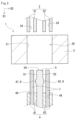
- FIG. 1 is a cross-sectional view of a mold according to an embodiment.
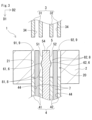
- FIG. 2 is a longitudinal sectional view of the mold according to the embodiment in a state where the upper punch, the lower punch, the first core, and the second core are not inserted into the die.
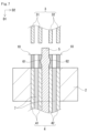
- FIG. 3 is a vertical cross-sectional view of the mold according to the embodiment in which the lower punch, the first core, and the second core are inserted into the die, but the upper punch is not inserted into the die.
- FIG. 4 is a perspective view of a powder compact molded using the mold according to the embodiment.
- FIG. 5 is an explanatory diagram of a step of filling powder in a method for manufacturing a powder compact using a mold according to an embodiment.
- FIG. 6 is an explanatory diagram of a step of molding a powder compact in a method for manufacturing a powder compact using the mold according to the embodiment.
- FIG. 7 is an explanatory diagram of a step of taking out a powder compact in the method for manufacturing a powder compact using the mold according to the embodiment.
- Patent Document 1 includes one cavity filled with powder.
- side pressure from the powder acts on the contact surface between the first die and the second die.
- seizure may occur between the first die and the second die due to the lateral pressure.
- One object of the present disclosure is to provide a mold that can suppress seizure of constituent members of the mold to each other during powder compression.
- the mold of the present disclosure can suppress seizure of constituent members of the mold to each other during powder compression.
- a mold according to an embodiment of the present disclosure includes a die having a hollow portion penetrating in a first direction, and dividing the hollow portion into a plurality of space portions arranged in parallel in a direction orthogonal to the first direction.
- the first core includes a first core, and an upper punch and a lower punch that are fitted into each of the plurality of spaces, and the first core is provided midway in the first direction on a side surface facing the plurality of spaces.
- the partial area includes a protrusion protruding from the side surface.
- the first core is referred to as a core in the disclosure of this specification, but depending on the configuration of the mold, it may be composed of a member generally called a punch.
- the name of the first core does not matter as long as it is a member that plays the role of dividing the hollow portion into a plurality of spaces.
- the mold of the present disclosure has a plurality of spaces, it is possible to produce a plurality of powder compacts with one compression. A partial area faces each space. Therefore, with the mold of the present disclosure, a powder compact having an undercut shape can be efficiently manufactured.
- a plurality of spaces are formed with the first core in between, so when the powder filled in each space is compressed, the lateral pressure acting on the inner peripheral surface of the die is It tends to act on the contact surface of the first core, and it hardly acts on the contact surface with the first core. Therefore, even if the first core and the die move relative to each other, sticking is unlikely to occur between the first core and the die.
- the plurality of spaces may be two.
- the first core that divides the hollow part into two spaces has a simpler configuration than the first core that divides the hollow part into three or more spaces.
- all of the plurality of spaces may have the same shape.
- a plurality of powder compacts having the same shape can be molded at the same time.
- the direction of lateral pressure from the powder tends to be symmetrical with respect to the first core.
- the powder is evenly compressed in the plurality of spaces, so that stable manufacturing can be achieved.
- the first core may be inserted into the hollow part from the same direction as the lower punch.
- the procedure for producing a powder compact is to first fill each of the plurality of spaces with powder while inserting the lower punch and the first core into the hollow part, and then insert the upper punch into each of the plurality of spaces. and compress the powder with the upper and lower punches.
- the lower punch and the first core are inserted into the hollow part from the same direction, it is easy to form a space filled with powder.
- the mold according to any one of (1) to (4) above may further include a second core inserted into each of the plurality of spaces.
- the degree of freedom in the shape of the powder compact to be manufactured is increased.
- the partial region may be the protrusion.
- a powder compact having a concave undercut shape can be manufactured.
- a method for manufacturing a powder compact includes the steps of preparing the mold according to any one of (1) to (6) above, and inserting the lower punch in the hollow part and the first mold. filling each of the plurality of spaces with powder while the core is inserted; and inserting the upper punch into each of the plurality of spaces, and compressing the powder with the upper punch and the lower punch. and a step of relatively moving the die and the upper punch with respect to the lower punch to take out the powder compact.
- a plurality of powder compacts having an undercut shape can be efficiently produced by one compression. Since the method for manufacturing a powder compact of the present disclosure uses the mold of the present disclosure, seizure is unlikely to occur between the first core and the die even if the first core and the die move relative to each other. .
- FIG. 1 shows the mold 1 with the constituent members of the mold 1 assembled and cut along a plane perpendicular to the first direction D1 so as to include the upper punch 3.
- FIG. 2 shows the mold 1 cut along a plane along the first direction D1 before the cavity 9 is formed.
- FIG. 3 shows the mold 1 cut along a plane along the first direction D1 with the cavity 9 configured.
- the upper punch 3 is located above the cavity 9.
- the first direction D1 is the vertical direction.
- the first direction D1 is also the direction in which the hollow portion 20 in the die 2 penetrates, as shown in FIG.
- the upper punch 3 and the lower punch 4 are fitted into the hollow part 20.
- the first direction D1 is shown by a single arrow, but the opposite direction to the first direction D1 may also be called the first direction D1.
- the first direction D1 is the direction in which the upper punch 3 and the lower punch 4 move with respect to the die 2, and is the direction in which the powder 9P is compressed.
- One of the features of the mold 1 of the embodiment is that it includes a first core 5 that divides the hollow part 20 in the die 2 into a plurality of spaces 8.
- the plurality of spaces 8 are arranged in parallel in a direction orthogonal to the first direction D1.
- two spaces 8 are arranged side by side in the second direction D2.
- a plurality of cavities 9 are configured corresponding to the plurality of spaces 8.
- the direction perpendicular to both the first direction D1 and the second direction D2 may be referred to as a third direction D3.
- the mold 1 of this example further includes a second core 7.
- the die 2 is a cylindrical member having a hollow portion 20 penetrating in the first direction D1.
- the hollow portion 20 has an end portion that opens upward and an end portion that opens downward.
- the hollow portion 20 is a space with both ends open.
- the shape of the hollow portion 20 corresponds to the outer shape of the powder compact 10 to be compression molded.
- the inner surface 21 of the die 2 constituting the hollow portion 20 is, for example, a smooth surface without unevenness.
- the opening edge of the hollow portion 20 viewed from the first direction D1 may be configured with a straight line or may be configured with a curved line.
- the opening edge in this example is configured by combining a plurality of straight lines and curved lines, for example.
- the shape of the opening edge in this example is approximately rectangular as shown in FIG. 1, and includes four straight lines and four curved lines.
- the four curved lines constitute corners that connect adjacent straight lines.
- the three-dimensional shape of the hollow portion 20 in this example is approximately rectangular parallelepiped and includes four planes.
- the die 2 is moved along the first direction D1 by a drive mechanism (not shown).
- the upper punch 3 is inserted into the upper part of the hollow part 20.
- a plurality of upper punches 3 are provided corresponding to the number of plurality of spaces 8, which will be described later.
- the upper punch 3 of this example includes a first upper punch 31 and a second upper punch 32 corresponding to the two spaces 8, as shown in FIG.
- Each of the first upper punch 31 and the second upper punch 32 is a columnar member.
- the outer shape of each end surface of the first upper punch 31 and the second upper punch 32 corresponds to the outer shape of the first end surface 11 of the powder compact 10 to be compression molded.
- the outer shape of each end face of the first upper punch 31 and the second upper punch 32 in this example is approximately rectangular.
- the substantially rectangular shape includes a range that is considered to be substantially rectangular, including a shape with chamfered corners or a shape with rounded corners.
- a part of the first core 5, which will be described later, is inserted between the first upper punch 31 and the second upper punch 32 when compressing the powder 9P.
- the first upper punch 31 and the second upper punch 32 are arranged with an interval such that a part of the first core 5 can freely slide.
- a through hole 34 is provided in each of the first upper punch 31 and the second upper punch 32.
- a portion of the second core 7, which will be described later, is slidably inserted into the through hole 34.
- Each of the first upper punch 31 and the second upper punch 32 slides along the first direction D1 with respect to the die 2, the first core 5, and the second core 7.
- the first upper punch 31 and the second upper punch 32 are moved along the first direction D1 by a drive mechanism (not shown).
- the first upper punch 31 and the second upper punch 32 may be operated in conjunction with each other.
- the first upper punch 31 and the second upper punch 32 are connected at a location where they are not inserted into the die 2, and the first upper punch 31 and the second upper punch 32 are simultaneously connected to the first upper punch 32 by a drive mechanism. It may also move along the direction D1.
- the first upper punch 31 and the second upper punch 32 may be operated independently of each other.
- the drive mechanism may include a first drive mechanism that operates only the first upper punch 31 and a second drive mechanism that operates only the second upper punch 32. Even if the first upper punch 31 and the second upper punch 32 are operated independently of each other, compression by the first upper punch 31 and compression by the second upper punch 32 are preferably performed at the same time. When compressed simultaneously, the powder in each cavity 9 is compressed evenly.
- the lower punch 4 is inserted into the lower part of the hollow part 20.
- a plurality of lower punches 4 are provided corresponding to the number of plurality of spaces 8, which will be described later.
- the lower punch 4 of this example includes a first lower punch 41 and a second lower punch 42 corresponding to the two spaces 8.
- the first upper punch 31 and the first lower punch 41 are a pair.
- the second upper punch 32 and the second lower punch 42 are a pair.
- Each of the first lower punch 41 and the second lower punch 42 is a columnar member.
- the outer shape of each end surface of the first lower punch 41 and the second lower punch 42 corresponds to the outer shape of the second end surface of the powder compact 10 to be compression molded.
- the second end surface is a surface facing the first end surface 11 of the powder compact 10 shown in FIG.
- the outer shape of each end face of the first lower punch 41 and the second lower punch 42 in this example is approximately rectangular.
- a part of the first core 5, which will be described later, is inserted between the first lower punch 41 and the second lower punch 42 when compressing the powder 9P.
- the first lower punch 41 and the second lower punch 42 are arranged with an interval such that a part of the first core 5 can freely slide.
- the first core 5 of this example is inserted into the hollow part 20 from the same direction as the lower punch 4. Therefore, the first core 5 of this example is always arranged between the first lower punch 41 and the second lower punch 42. In other words, the first lower punch 41 and the second lower punch 42 of this example sandwich the first core 5.
- a through hole 44 is provided in each of the first lower punch 41 and the second lower punch 42.
- a portion of the second core 7, which will be described later, is slidably inserted into the through hole 44.
- the second core 7 of this example is inserted into the hollow part 20 from the same direction as the lower punch 4. Therefore, the second core 7 of this example is always arranged inside each through hole 44 of the first lower punch 41 and the second lower punch 42.
- Each of the first lower punch 41 and the second lower punch 42 slides along the first direction D1 with respect to the die 2, the first core 5, and the second core 7.
- the lower punch 4 is usually fixed.
- the die 2, the upper punch 3, and the first core 5 move with respect to the lower punch 4 along the first direction D1.
- the first core 5 is a columnar member that divides the hollow portion 20 into a plurality of space portions 8 arranged in parallel in a direction perpendicular to the first direction D1.
- the first core 5 is arranged at a position that divides the hollow part 20 into a plurality of spaces 8.
- the first core 5 of this example is arranged at a position that divides the hollow part 20 into two spaces 8, a first space 81 and a second space 82.
- two cavities 9, a first cavity 91 and a second cavity 92 are configured corresponding to the number of spaces 8.
- the shape of the first core 5 is determined in accordance with the shape and number of powder compacts 10 to be compression molded.
- the first core 5 in this example has a substantially rectangular parallelepiped shape.
- the substantially rectangular parallelepiped shape includes a shape with chamfered corners or a shape with rounded corners, and includes a range that is considered to be substantially a rectangular parallelepiped.
- the first core 5 of this example includes a side surface 51 facing the first space 81 , a side surface 52 facing the second space 82 , sliding surfaces 53 , 53 facing the die 2 , and an end surface 54 .
- the first core 5 of this example has a substantially rectangular cross-sectional shape with a length in the third direction D3 longer than a length in the second direction D2.
- the first core 5 includes partial regions 6 provided on side surfaces 51 and 52, as shown in FIGS. 2 and 3.
- the partial region 6 is provided halfway in the first direction D1 on the side surfaces 51 and 52.
- Partial region 6 includes protrusions projecting from side surfaces 51 and 52.
- the protrusion protrudes in the second direction D2.
- the shape of the protrusion does not matter.
- the protrusion has a curved cross-sectional shape, as shown in FIGS. 2 and 3, for example. More specifically, the protrusion in this example has an arcuate cross-sectional shape surrounded by a circular arc and a chord.
- the protrusion is provided in at least a portion of the partial region 6.
- the protrusion may be provided in a part of the partial region 6 or may be provided in the entire region of the partial region 6.
- the partial region 6 may include a partial recess.
- the partial region 6 in this example is a protrusion.
- the partial region 6 provides an undercut portion 15 shown in FIG. 4 to the powder compact 10 to be compression molded.
- the undercut portion 15 has an undercut shape.
- the undercut shape includes a concave shape depressed in a second direction D2 orthogonal to the first direction D1.
- the undercut portion 15 provided in the powder compact 10 has a concave shape.
- the partial area 6 is shown by a broken line.
- the partial region 6 includes a first partial region 61 provided on the side surface 51 and a second partial region 62 provided on the side surface 52. Both the first partial region 61 and the second partial region 62 are protrusions.
- the protrusion in this example is provided so as to protrude in the second direction D2 and extend in the third direction D3.
- the protrusion in this example is a columnar body that has an arcuate cross-sectional shape and extends along the third direction D3.
- the protrusion may be provided so as to extend obliquely in a direction intersecting the third direction D3.
- the shape of the first partial region 61 and the shape of the second partial region 62 are the same.
- the size of the first partial area 61 and the size of the second partial area 62 are the same.
- the first partial area 61 and the second partial area 62 are provided symmetrically.
- a plurality of powder compacts 10 having the same undercut portion 15 can be manufactured at the same time.
- At least one partial region 6 is provided on each side surface 51, 52.
- One partial region 6 may be provided on each side surface 51, 52 as in this example.
- a plurality of partial regions 6 may be provided on each side surface 51, 52, such as being divided in the third direction D3.
- the first partial region 61 provided on the side surface 51 and the second partial region 62 provided on the side surface 52 do not have to have completely the same shape and size.
- the powder 9P in each cavity 9 is evenly compressed, and stable manufacturing can be achieved. .
- the powder compact 10 to be compression molded is provided with an undercut portion 15 in which the partial region 6 shown in FIGS. 2 and 3 is reversed.
- the end surface 54 is exposed to the outside and is not in contact with other constituent members of the mold 1.
- the first core 5 of this example is inserted into the hollow part 20 from the same direction as the lower punch 4. That is, the first core 5 of this example is inserted into the hollow part 20 from below the die 2.
- the first core 5 of this example has a structure in which it is fitted into the hollow portion 20 together with the lower punch 4 from the same direction as the lower punch 4.
- the first core 5 is moved along the first direction D1 by a drive mechanism (not shown).
- the first core 5 is positioned, for example, by a block not shown.
- the second core 7 is a columnar member inserted into each of the plurality of spaces 8 .
- the second core 7 is inserted into each space 8 from the same direction as the lower punch 4. That is, the second core 7 is inserted into each space 8 from below the die 2 .
- the second core 7 has a structure in which it is fitted into the hollow portion 20 together with the lower punch 4 and the first core 5 from the same direction as the lower punch 4 .
- the second core 7 is inserted into the through hole 44 of each of the first lower punch 41 and the second lower punch 42.
- the second core 7 forms a through hole 16 in the powder compact 10 to be compression molded.
- the shape of the second core 7 corresponds to the shape of the through hole 16 shown in FIG.
- the shape of the second core 7 in this example is cylindrical.
- the hollow part 20 is divided into a plurality of spaces 8 by the first core 5.
- two spaces 8, a first space 81 and a second space 82 are configured by the first core 5.
- the shape of the first space 81 and the shape of the second space 82 are the same.
- the size of the first space 81 and the size of the second space 82 are the same.
- the orientation of the first space 81 and the orientation of the second space 82 may be different.
- the orientation of the first space 81 and the orientation of the second space 82 are symmetrical with respect to the first core 5.
- first lower punch 41 When the first lower punch 41 is placed in the first space 81, a first cavity 91 is formed in the first space 81.
- second lower punch 42 When the second lower punch 42 is placed in the second space 82, a second cavity 92 is formed in the second space 82.
- the second core 7 is further arranged in each of the first space 81 and the second space 82.
- the first cavity 91 and the second cavity 92 have the same shape.
- each of the first cavity 91 and the second cavity 92 has a cylindrical shape.
- the mold 1 of this example can simultaneously mold two powder compacts 10 having the same shape and size.
- the number of the plurality of spaces 8 may be three or more. Three or more spaces 8 are arranged in parallel in the second direction D2, for example. When the opening edge of the hollow part 20 when viewed from the first direction D1 is circular, three or more spaces 8 may be arranged in parallel around the axis of the hollow part 20.
- the plurality of spaces 8 may include spaces 8 of different shapes.
- the shape of the first space 81 and the shape of the second space 82 may be different.
- the plurality of spaces 8 may include spaces 8 of different sizes.
- the size of the first space 81 and the size of the second space 82 may be different.
- the powder compact 10 manufactured by the mold 1 described above includes an undercut portion 15, as shown in FIG.
- the undercut portion 15 is a recessed portion depressed from the side surface 13.
- the powder compact 10 of this example further includes a through hole 16.
- the method for producing a powder compact includes a preparation step, a filling step, a molding step, and a take-out step, which are performed in this order.
- the mold 1 described above is prepared.
- the shapes of the die 2, upper punch 3, lower punch 4, first core 5, and second core 7 in the mold 1 are such that a plurality of cavities 9 are formed corresponding to the shape of the powder compact 10 to be manufactured. can be selected as appropriate.
- each of the plurality of spaces 8 is filled with powder 9P while the lower punch 4 and first core 5 are inserted into the hollow part 20 shown in FIGS. 2 and 3.
- the space 8 in the state in which the lower punch 4 and the first core 5 are inserted into the hollow part 20 is a cavity 9.
- the second core 7 is also inserted into the hollow part 20.
- the end surface of the second core 7 is arranged above the end surface of the lower punch 4.
- the end surface 54 of the first core 5 and each end surface of the second core 7 are on the same plane as the end surface of the die 2, for example.
- the upper punch 3 is inserted into each of the plurality of spaces 8 shown in FIG. 3, and the powder 9P is compressed by the upper punch 3 and the lower punch 4.
- the first upper punch 31 and the first lower punch 41 compress the powder 9P in the first cavity 91
- the second upper punch 32 and the second lower punch 42 compress the powder 9P in the second cavity 92. Compress the powder 9P inside.
- the first upper punch 31 and the second upper punch 32 are simultaneously moved downward along the first direction D1 by a drive mechanism (not shown). At this time, the end surface 54 of the first core 5 is not in contact with other constituent members of the mold 1.
- the powder 9P filled inside each of the first cavity 91 and the second cavity 92 is compressed, and two powder compacts 10 are molded at the same time.
- powder compacts 10 of a number corresponding to the three or more spaces 8 are molded at the same time.
- the lateral pressure from the powder 9P in each cavity 9 is hardly applied to the sliding surface 53 of the first core 5. Therefore, even if the first core 5 and the die 2 move relative to each other, seizure is unlikely to occur between the first core 5 and the die 2.
- two powder compacts 10 are molded with the first core 5 in between. Therefore, the direction of the lateral pressure from the powder 9P becomes symmetrical with respect to the first core 5, and the lateral pressure is canceled out.
- two powder compacts 10 with small local variations in density can be manufactured.
- Each powder compact 10 is positioned outside the hollow part 20 of the die 2 through the taking-out process.
- Each powder compact 10 located outside the hollow portion 20 has a surface other than the contact surface with the first core 5 exposed.
- Each powder compact 10 located outside the hollow part 20 is movable in a direction away from the first core 5. By peeling off each powder compact 10 from the first core 5, each powder compact 10 can be taken out. In this example, the two powder compacts 10 are moved away from each other along the second direction D2. Through this removal step, the powder compact 10 having the undercut portion 15 shown in FIG. 4 can be easily removed from the mold 1.
Landscapes
- Engineering & Computer Science (AREA)
- Mechanical Engineering (AREA)
- Powder Metallurgy (AREA)
Priority Applications (3)
| Application Number | Priority Date | Filing Date | Title |
|---|---|---|---|
| JP2024540307A JPWO2024034287A1 (https=) | 2022-08-12 | 2023-06-30 | |
| DE112023003462.1T DE112023003462T5 (de) | 2022-08-12 | 2023-06-30 | Form und Verfahren zur Herstellung eines pulvergeformten Materials |
| CN202380058396.2A CN119604404A (zh) | 2022-08-12 | 2023-06-30 | 模具、及粉末成形体的制造方法 |
Applications Claiming Priority (2)
| Application Number | Priority Date | Filing Date | Title |
|---|---|---|---|
| JP2022-128789 | 2022-08-12 | ||
| JP2022128789 | 2022-08-12 |
Publications (1)
| Publication Number | Publication Date |
|---|---|
| WO2024034287A1 true WO2024034287A1 (ja) | 2024-02-15 |
Family
ID=89851400
Family Applications (1)
| Application Number | Title | Priority Date | Filing Date |
|---|---|---|---|
| PCT/JP2023/024430 Ceased WO2024034287A1 (ja) | 2022-08-12 | 2023-06-30 | 金型、及び粉末成形体の製造方法 |
Country Status (4)
| Country | Link |
|---|---|
| JP (1) | JPWO2024034287A1 (https=) |
| CN (1) | CN119604404A (https=) |
| DE (1) | DE112023003462T5 (https=) |
| WO (1) | WO2024034287A1 (https=) |
Cited By (1)
| Publication number | Priority date | Publication date | Assignee | Title |
|---|---|---|---|---|
| WO2026014393A1 (ja) * | 2024-07-09 | 2026-01-15 | 住友電工焼結合金株式会社 | 粉末成形体の製造装置、および粉末成形体の製造方法 |
Citations (6)
| Publication number | Priority date | Publication date | Assignee | Title |
|---|---|---|---|---|
| JPS63119630U (https=) * | 1987-01-28 | 1988-08-02 | ||
| JPS63230801A (ja) * | 1987-03-20 | 1988-09-27 | Mitsubishi Metal Corp | 焼結ヘリカルギヤの成形方法 |
| JP2001059106A (ja) * | 1999-08-24 | 2001-03-06 | Hitachi Powdered Metals Co Ltd | 軸受の製造方法 |
| JP2003073715A (ja) * | 2001-09-05 | 2003-03-12 | Nippon Kagaku Yakin Co Ltd | 焼結含油軸受の製造方法 |
| JP2006022366A (ja) * | 2004-07-07 | 2006-01-26 | Sumitomo Denko Shoketsu Gokin Kk | 段付穴の成形方法及びその方法で成形して製造された段付穴を有する焼結部品 |
| CN203556875U (zh) * | 2013-11-01 | 2014-04-23 | 横店集团东磁股份有限公司 | 一种粉末冶金错动位移成型模具 |
Family Cites Families (4)
| Publication number | Priority date | Publication date | Assignee | Title |
|---|---|---|---|---|
| JPS6130037U (ja) * | 1984-07-21 | 1986-02-22 | マツダ株式会社 | 粉末冶金圧粉金型 |
| JP2000263298A (ja) * | 1999-03-17 | 2000-09-26 | Hitachi Powdered Metals Co Ltd | 鉤形部品の成形用金型装置 |
| JP2004181487A (ja) * | 2002-12-03 | 2004-07-02 | Mitsubishi Materials Corp | 異形品の成形方法及び成形金型 |
| JP2009034715A (ja) * | 2007-08-03 | 2009-02-19 | Sumitomo Electric Ind Ltd | 粉末成形用金型および該粉末成形用金型への粉末充填方法 |
-
2023
- 2023-06-30 WO PCT/JP2023/024430 patent/WO2024034287A1/ja not_active Ceased
- 2023-06-30 CN CN202380058396.2A patent/CN119604404A/zh active Pending
- 2023-06-30 DE DE112023003462.1T patent/DE112023003462T5/de active Pending
- 2023-06-30 JP JP2024540307A patent/JPWO2024034287A1/ja active Pending
Patent Citations (6)
| Publication number | Priority date | Publication date | Assignee | Title |
|---|---|---|---|---|
| JPS63119630U (https=) * | 1987-01-28 | 1988-08-02 | ||
| JPS63230801A (ja) * | 1987-03-20 | 1988-09-27 | Mitsubishi Metal Corp | 焼結ヘリカルギヤの成形方法 |
| JP2001059106A (ja) * | 1999-08-24 | 2001-03-06 | Hitachi Powdered Metals Co Ltd | 軸受の製造方法 |
| JP2003073715A (ja) * | 2001-09-05 | 2003-03-12 | Nippon Kagaku Yakin Co Ltd | 焼結含油軸受の製造方法 |
| JP2006022366A (ja) * | 2004-07-07 | 2006-01-26 | Sumitomo Denko Shoketsu Gokin Kk | 段付穴の成形方法及びその方法で成形して製造された段付穴を有する焼結部品 |
| CN203556875U (zh) * | 2013-11-01 | 2014-04-23 | 横店集团东磁股份有限公司 | 一种粉末冶金错动位移成型模具 |
Cited By (2)
| Publication number | Priority date | Publication date | Assignee | Title |
|---|---|---|---|---|
| WO2026014393A1 (ja) * | 2024-07-09 | 2026-01-15 | 住友電工焼結合金株式会社 | 粉末成形体の製造装置、および粉末成形体の製造方法 |
| JP7841679B1 (ja) * | 2024-07-09 | 2026-04-07 | 住友電工焼結合金株式会社 | 粉末成形体の製造装置、および粉末成形体の製造方法 |
Also Published As
| Publication number | Publication date |
|---|---|
| CN119604404A (zh) | 2025-03-11 |
| JPWO2024034287A1 (https=) | 2024-02-15 |
| DE112023003462T5 (de) | 2025-07-03 |
Similar Documents
| Publication | Publication Date | Title |
|---|---|---|
| KR20140047700A (ko) | 절삭 인서트 제조를 위한 장치 및 방법 | |
| WO2024034287A1 (ja) | 金型、及び粉末成形体の製造方法 | |
| CN101918190A (zh) | 在基于纸板的容器内形成分隔体的模具系统 | |
| JP2003077769A (ja) | 固体電解コンデンサ用ペレットの製造方法およびその製造装置 | |
| JP7018494B2 (ja) | 成型金型、成型方法 | |
| JP7841679B1 (ja) | 粉末成形体の製造装置、および粉末成形体の製造方法 | |
| CN211788659U (zh) | 钽电阳极芯子成型模具 | |
| JP6811566B2 (ja) | 複層成形品の製造装置及び製造方法 | |
| CN100473522C (zh) | 成型用模具 | |
| JP3004417U (ja) | ボビン形コア | |
| JP2002307199A (ja) | 粉末の圧縮成形方法及びその装置 | |
| JP4523121B2 (ja) | 粉末成形体の製造方法 | |
| JP2002045998A (ja) | プレス成形機 | |
| JP2007092100A (ja) | 焼結金属部材およびその製造方法 | |
| JP3649368B2 (ja) | 圧粉体の成形方法 | |
| CN109153075B (zh) | 成型模具及成型方法 | |
| JPH10296498A (ja) | 粉末成形体の製造方法 | |
| JP2025141368A (ja) | 金属製筐体の製造方法および押出成型用金型 | |
| JP7686311B1 (ja) | 射出成形型 | |
| JP2000263298A (ja) | 鉤形部品の成形用金型装置 | |
| JP2024002314A (ja) | 金型 | |
| CN217021412U (zh) | 冲坑模具结构及电池 | |
| JP6354893B1 (ja) | 切削インサート用圧粉体の粉末成形プレス方法および粉末成形プレス装置 | |
| JPH07258704A (ja) | 粉末成形方法及び粉末成形装置 | |
| JP2024021756A (ja) | 樹脂成形体打抜型 |
Legal Events
| Date | Code | Title | Description |
|---|---|---|---|
| 121 | Ep: the epo has been informed by wipo that ep was designated in this application |
Ref document number: 23852270 Country of ref document: EP Kind code of ref document: A1 |
|
| WWE | Wipo information: entry into national phase |
Ref document number: 2024540307 Country of ref document: JP |
|
| WWE | Wipo information: entry into national phase |
Ref document number: 2501000757 Country of ref document: TH |
|
| WWE | Wipo information: entry into national phase |
Ref document number: 202380058396.2 Country of ref document: CN |
|
| WWE | Wipo information: entry into national phase |
Ref document number: 202547010886 Country of ref document: IN |
|
| WWP | Wipo information: published in national office |
Ref document number: 202547010886 Country of ref document: IN |
|
| WWP | Wipo information: published in national office |
Ref document number: 202380058396.2 Country of ref document: CN |
|
| WWE | Wipo information: entry into national phase |
Ref document number: 112023003462 Country of ref document: DE |
|
| WWP | Wipo information: published in national office |
Ref document number: 112023003462 Country of ref document: DE |
|
| 122 | Ep: pct application non-entry in european phase |
Ref document number: 23852270 Country of ref document: EP Kind code of ref document: A1 |