WO2024029207A1 - 液晶ポリマーフィルムおよびこれを備えた積層体、ならびに、液晶ポリマーフィルムの製造方法 - Google Patents
液晶ポリマーフィルムおよびこれを備えた積層体、ならびに、液晶ポリマーフィルムの製造方法 Download PDFInfo
- Publication number
- WO2024029207A1 WO2024029207A1 PCT/JP2023/022058 JP2023022058W WO2024029207A1 WO 2024029207 A1 WO2024029207 A1 WO 2024029207A1 JP 2023022058 W JP2023022058 W JP 2023022058W WO 2024029207 A1 WO2024029207 A1 WO 2024029207A1
- Authority
- WO
- WIPO (PCT)
- Prior art keywords
- lcp
- liquid crystal
- crystal polymer
- polymer film
- inorganic filler
- Prior art date
- Legal status (The legal status is an assumption and is not a legal conclusion. Google has not performed a legal analysis and makes no representation as to the accuracy of the status listed.)
- Ceased
Links
Images


Classifications
-
- C—CHEMISTRY; METALLURGY
- C08—ORGANIC MACROMOLECULAR COMPOUNDS; THEIR PREPARATION OR CHEMICAL WORKING-UP; COMPOSITIONS BASED THEREON
- C08J—WORKING-UP; GENERAL PROCESSES OF COMPOUNDING; AFTER-TREATMENT NOT COVERED BY SUBCLASSES C08B, C08C, C08F, C08G or C08H
- C08J5/00—Manufacture of articles or shaped materials containing macromolecular substances
- C08J5/18—Manufacture of films or sheets
-
- B—PERFORMING OPERATIONS; TRANSPORTING
- B29—WORKING OF PLASTICS; WORKING OF SUBSTANCES IN A PLASTIC STATE IN GENERAL
- B29D—PRODUCING PARTICULAR ARTICLES FROM PLASTICS OR FROM SUBSTANCES IN A PLASTIC STATE
- B29D7/00—Producing flat articles, e.g. films or sheets
- B29D7/01—Films or sheets
-
- B—PERFORMING OPERATIONS; TRANSPORTING
- B32—LAYERED PRODUCTS
- B32B—LAYERED PRODUCTS, i.e. PRODUCTS BUILT-UP OF STRATA OF FLAT OR NON-FLAT, e.g. CELLULAR OR HONEYCOMB, FORM
- B32B15/00—Layered products comprising a layer of metal
- B32B15/04—Layered products comprising a layer of metal comprising metal as the main or only constituent of a layer, which is next to another layer of the same or of a different material
- B32B15/08—Layered products comprising a layer of metal comprising metal as the main or only constituent of a layer, which is next to another layer of the same or of a different material of synthetic resin
- B32B15/09—Layered products comprising a layer of metal comprising metal as the main or only constituent of a layer, which is next to another layer of the same or of a different material of synthetic resin comprising polyesters
-
- B—PERFORMING OPERATIONS; TRANSPORTING
- B32—LAYERED PRODUCTS
- B32B—LAYERED PRODUCTS, i.e. PRODUCTS BUILT-UP OF STRATA OF FLAT OR NON-FLAT, e.g. CELLULAR OR HONEYCOMB, FORM
- B32B27/00—Layered products comprising a layer of synthetic resin
- B32B27/36—Layered products comprising a layer of synthetic resin comprising polyesters
-
- C—CHEMISTRY; METALLURGY
- C09—DYES; PAINTS; POLISHES; NATURAL RESINS; ADHESIVES; COMPOSITIONS NOT OTHERWISE PROVIDED FOR; APPLICATIONS OF MATERIALS NOT OTHERWISE PROVIDED FOR
- C09K—MATERIALS FOR MISCELLANEOUS APPLICATIONS, NOT PROVIDED FOR ELSEWHERE
- C09K19/00—Liquid crystal materials
- C09K19/04—Liquid crystal materials characterised by the chemical structure of the liquid crystal components, e.g. by a specific unit
- C09K19/38—Polymers
- C09K19/3804—Polymers with mesogenic groups in the main chain
- C09K19/3809—Polyesters; Polyester derivatives, e.g. polyamides
-
- C—CHEMISTRY; METALLURGY
- C09—DYES; PAINTS; POLISHES; NATURAL RESINS; ADHESIVES; COMPOSITIONS NOT OTHERWISE PROVIDED FOR; APPLICATIONS OF MATERIALS NOT OTHERWISE PROVIDED FOR
- C09K—MATERIALS FOR MISCELLANEOUS APPLICATIONS, NOT PROVIDED FOR ELSEWHERE
- C09K19/00—Liquid crystal materials
- C09K19/52—Liquid crystal materials characterised by components which are not liquid crystals, e.g. additives with special physical aspect: solvents, solid particles
-
- C—CHEMISTRY; METALLURGY
- C09—DYES; PAINTS; POLISHES; NATURAL RESINS; ADHESIVES; COMPOSITIONS NOT OTHERWISE PROVIDED FOR; APPLICATIONS OF MATERIALS NOT OTHERWISE PROVIDED FOR
- C09K—MATERIALS FOR MISCELLANEOUS APPLICATIONS, NOT PROVIDED FOR ELSEWHERE
- C09K19/00—Liquid crystal materials
- C09K19/52—Liquid crystal materials characterised by components which are not liquid crystals, e.g. additives with special physical aspect: solvents, solid particles
- C09K19/54—Additives having no specific mesophase characterised by their chemical composition
- C09K19/542—Macromolecular compounds
- C09K19/544—Macromolecular compounds as dispersing or encapsulating medium around the liquid crystal
-
- C—CHEMISTRY; METALLURGY
- C08—ORGANIC MACROMOLECULAR COMPOUNDS; THEIR PREPARATION OR CHEMICAL WORKING-UP; COMPOSITIONS BASED THEREON
- C08J—WORKING-UP; GENERAL PROCESSES OF COMPOUNDING; AFTER-TREATMENT NOT COVERED BY SUBCLASSES C08B, C08C, C08F, C08G or C08H
- C08J2367/00—Characterised by the use of polyesters obtained by reactions forming a carboxylic ester link in the main chain; Derivatives of such polymers
- C08J2367/02—Polyesters derived from dicarboxylic acids and dihydroxy compounds
-
- C—CHEMISTRY; METALLURGY
- C09—DYES; PAINTS; POLISHES; NATURAL RESINS; ADHESIVES; COMPOSITIONS NOT OTHERWISE PROVIDED FOR; APPLICATIONS OF MATERIALS NOT OTHERWISE PROVIDED FOR
- C09K—MATERIALS FOR MISCELLANEOUS APPLICATIONS, NOT PROVIDED FOR ELSEWHERE
- C09K19/00—Liquid crystal materials
- C09K19/52—Liquid crystal materials characterised by components which are not liquid crystals, e.g. additives with special physical aspect: solvents, solid particles
- C09K2019/521—Inorganic solid particles
Definitions
- the present disclosure relates to a liquid crystal polymer film, a laminate including the same, and a method for manufacturing a liquid crystal polymer film.
- Patent Document 1 JP-A-2006-233118 discloses a resin composition for antenna parts that is characterized by containing a liquid crystal resin and ceramic powder.
- Patent Document 2 describes an insulating region that is formed inside a substrate body made of a liquid crystal polymer, and in which functional filler for forming an element is dispersed.
- An element-embedded substrate is disclosed that has an element-forming layer.
- a liquid crystal polymer film formed by mixing an inorganic filler with a high dielectric constant with a liquid crystal polymer has a high dielectric constant.
- the liquid crystal polymer has a small linear expansion coefficient in the molecular orientation direction and a large linear expansion coefficient in the direction perpendicular to the orientation direction. Therefore, in the liquid crystal polymer film, it is preferable that the molecules of the liquid crystal polymer are oriented along the in-plane direction of the main surface of the film in order to reduce the coefficient of linear expansion in the in-plane direction of the main surface of the film.
- FCCL flexible copper clad laminate
- the present disclosure has been made in view of the above problems, and provides a liquid crystal polymer film in which the dielectric constant is increased by adding an inorganic filler while suppressing the increase in linear expansion coefficient in the in-plane direction of the main surface of the film.
- the purpose is to provide.
- a liquid crystal polymer film based on the present disclosure includes a liquid crystal polymer and an inorganic filler.
- the liquid crystal polymer film has a dielectric constant of 5 or more and 10 or less.
- the average value of the distance between the barycentric coordinates of the inorganic filler particles in the liquid crystal polymer film is 0.5 ⁇ m or more and 2.0 ⁇ m or less.
- the inorganic filler is not locally densely present. Therefore, it is possible to suppress the orientation of the liquid crystal polymer molecules in the in-plane direction of the main surface of the film from being inhibited by the inorganic filler. Furthermore, it is possible to provide a liquid crystal polymer film in which the dielectric constant is increased by adding an inorganic filler while suppressing an increase in the coefficient of linear expansion in the in-plane direction of the main surface of the film.
- FIG. 1 is a schematic cross-sectional view of a laminate according to an embodiment of the present disclosure.
- 1 is an image showing an example of a photograph taken of a cross section of an LCP film according to an embodiment of the present disclosure using a backscattered electron image of an SEM.
- FIG. 2 is a diagram showing an example of a binarized image obtained by binarizing a photographed image of a cross section of an LCP film according to an embodiment of the present disclosure.
- FIG. 2 is a diagram schematically showing how the average value of the distance between barycentric coordinates of an inorganic filler is measured from a binarized image of a cross section of an LCP film according to an embodiment of the present disclosure.
- FIG. 2 is a flow diagram showing a manufacturing process of a liquid crystal polymer film according to an embodiment of the present disclosure.
- 3 is a cross-sectional view schematically showing a laminate according to Comparative Example 1.
- a laminate according to an embodiment of the present disclosure includes a liquid crystal polymer film (LCP film) and a conductor layer laminated on the liquid crystal polymer film.
- LCP film liquid crystal polymer film
- the coefficient of linear expansion in the in-plane direction of the main surface of the liquid crystal polymer film is suppressed to be relatively low as described later, so that the relationship between the liquid crystal polymer film and the conductor layer is suppressed to a relatively low value.
- the difference in linear expansion coefficient is relatively small. Therefore, the laminate according to this embodiment has suppressed warpage.
- the amount of warpage of the laminate is preferably 10 mm or less.
- the laminate can be suitably used as a flexible copper-clad laminate.
- the amount of warpage of a laminate is defined as a test piece cut out into 150 mm squares when looking at the laminate from the stacking direction, and placed on the reference plane so that the conductive layer is in contact with the reference plane. After that, the distance from the reference plane was measured for each of the four corners of the test piece, and the value was the average of these four measured distances.
- the conductor layer may be a copper foil made of copper, for example. If the conductor layer is copper foil, the laminate may be a so-called flexible copper clad laminate (FCCL).
- FCCL flexible copper clad laminate
- the conductor layer may be formed in a circuit pattern. Furthermore, a via hole may be formed in the liquid crystal polymer film, and a resin layer and another conductor layer may be further laminated on the conductive layer. In this way, the laminate may be a so-called flexible printed circuit board.
- a liquid crystal polymer film (LCP film) according to an embodiment of the present disclosure includes a liquid crystal polymer (LCP) and an inorganic filler.
- the liquid crystal polymer film according to an embodiment of the present disclosure has a relative dielectric constant when measured by applying a high frequency signal of 12 GHz at an ambient temperature of 25° C. using the cavity resonator method in accordance with JIS R 1641. It is 5 or more and 10 or less. If the dielectric constant of the liquid crystal polymer film is less than 5, when the liquid crystal polymer film is used for a high frequency antenna substrate, the area of the radiation electrode of the high frequency antenna substrate cannot be made sufficiently small. Furthermore, if the dielectric constant of the liquid crystal polymer film is more than 10, the antenna efficiency will deteriorate.
- the liquid crystal polymer film according to an embodiment of the present disclosure has a dielectric loss tangent when measured by applying a high frequency signal of 30 GHz at an ambient temperature of 25° C. using the cavity resonator method in accordance with JIS R 1641. , preferably 0.01 or less. If the dielectric loss tangent of the LCP film is 0.01 or less, deterioration of antenna efficiency can be suppressed when the LCP film is used as a high frequency antenna substrate.
- liquid crystal polymer examples include, but are not limited to, thermotropic liquid crystal polymers.
- the thermotropic liquid crystal polymer is, for example, an aromatic polyester synthesized mainly from monomers such as aromatic diol, aromatic dicarboxylic acid, aromatic hydroxycarboxylic acid, etc., and exhibits liquid crystallinity when melted.
- the molecules of the liquid crystal polymer have a negative coefficient of linear expansion (CTE) in the axial direction of the molecular axis, and a positive CTE in the radial direction of the molecular axis.
- CTE negative coefficient of linear expansion
- thermotropic liquid crystal polymers that do not have amide bonds include copolymers of parahydroxybenzoic acid, terephthalic acid, and dihydroxybiphenyl (parahydroxybenzoic acid and (block copolymer with ethylene terephthalate), or parahydroxybenzoic acid and 2,6-hydroxynaphthoate having a melting point between type 1 liquid crystal polymer and type 2 liquid crystal polymer called 1.5 type (or type 3).
- examples include copolymers (block copolymers) with acids.
- liquid crystal polymer powder The LCP film according to an embodiment of the present disclosure can be manufactured by a manufacturing method described below using liquid crystal polymer powder (LCP powder) made of the above-mentioned liquid crystal polymer.
- LCP powder includes fibrous particles made of liquid crystal polymer (liquid crystal polymer fiber: LCP fiber).
- the LCP fibers contained in the LCP powder are not particularly limited as long as they contain fibrous parts.
- the fibrous portion may be linear or may have branches or the like.
- the average diameter of the LCP fibers is 2 ⁇ m or less, preferably 1.4 ⁇ m or less, and more preferably 1 ⁇ m or less.
- the average diameter of the LCP fibers is, for example, 0.07 ⁇ m or more.
- the smaller the average diameter of the LCP fibers the less overlap between the LCP fibers during LCP film production. This facilitates in-plane orientation of LCP during LCP film production, reducing the coefficient of linear expansion (CTE) in the main plane of the LCP film and the amount of warpage of the flexible copper clad laminate (FCCL).
- the average aspect ratio of the LCP fibers is preferably 10 or more and 500 or less, more preferably 10 or more and 300 or less.
- the average diameter and average aspect ratio of LCP fibers are measured by the following method.
- LCP powder made of LCP fibers to be measured is dispersed in ethanol to prepare a slurry in which 0.01% by mass of LCP powder is dispersed.
- the slurry is prepared so that the water content in the slurry is 1% by mass or less.
- the slurry on the slide glass is air-dried. By air drying the slurry, LCP powder is placed on the glass slide.
- the image data was collected by changing the magnification of the SEM to 500x, 3000x, or 10000x as appropriate. do.
- each LCP fiber is measured using the collected image data.
- the direction of the straight line connecting both ends of is defined as the longitudinal direction.
- the length of a straight line connecting both ends of the longest route is measured as the longitudinal dimension.
- the size of each particle of LCP powder in the direction perpendicular to the longitudinal direction is measured at three different points in the longitudinal direction.
- the average value of the dimensions measured at these three points is defined as the width direction dimension (fiber diameter) per particle of LCP powder.
- the average value of the fiber diameters measured for 100 LCP fibers is defined as the average diameter.
- the ratio of the longitudinal dimension to the fiber diameter [longitudinal dimension/fiber diameter] is calculated and used as the aspect ratio of the LCP fiber. Then, the average value of the aspect ratios measured for 100 LCP fibers is defined as the average aspect ratio.
- fibrous particles may be included in the LCP powder as an aggregate of fibrous particles.
- the axial direction of the LCP molecules constituting the fibrous particles tends to coincide with the longitudinal direction of the fibrous particles.
- destruction occurs between multiple domains formed by bundles of LCP molecules, so that the axial direction of the LCP molecules is aligned along the longitudinal direction of the fibrous particles. This is thought to be due to the orientation.
- the content (number ratio) of particles other than fibrous particles is preferably 20% or less.
- the content (number ratio) of particles other than fibrous particles is preferably 20% or less.
- particles with a maximum height of 10 ⁇ m or less are fibrous particles, and particles with a maximum height of more than 10 ⁇ m are lumpy particles.
- the LCP powder has a D50 (average particle size) value of 13 ⁇ m or less as measured by particle size measurement using a particle size distribution measuring device using a laser diffraction scattering method.
- the filler raw material for example, powders of inorganic oxides such as talc, alumina, silica, alkaline earth metal titanates, carbon powders, ceramic powders, glass powders, etc. can be used.
- the inorganic filler is preferably an alkaline earth metal titanate. Since alkaline earth metal titanate is a ferroelectric substance, by adding alkaline earth metal titanate to liquid crystal polymer, the dielectric constant of the liquid crystal polymer film can be effectively increased. Examples of the alkaline earth metal titanate include barium titanate (BaTiO 3 ), calcium titanate (CaTiO 3 ), and strontium titanate (SrTiO 3 ).
- the inorganic filler is preferably barium titanate. Since barium titanate is a ferroelectric substance with a particularly high dielectric constant, it is possible to more effectively increase the dielectric constant of the liquid crystal polymer film. Moreover, it is also preferable that the inorganic filler is calcium titanate or strontium titanate. By adding calcium titanate or strontium titanate, increase in dielectric loss of the liquid crystal polymer film can be suppressed.
- One type of filler raw material may be used alone, or two or more types may be used in combination.
- the shape of the filler raw material is not particularly limited, and amorphous fillers, plate-shaped fillers, granular fillers, etc. can be used.
- the inorganic filler of the present disclosure preferably includes a flat filler.
- "flat filler” in one embodiment of the present disclosure refers to a filler obtained by heating and compressing a filler used as a raw material (hereinafter sometimes referred to as "filler raw material"), a filler raw material that is flat, a spherical filler, etc. This includes fillers that are formed by agglomerating filler raw materials into flat aggregates.
- the inorganic filler has a D50 (average particle size) value of 0.5 ⁇ m or more and 1.5 ⁇ m or less, as measured by particle size measurement using a particle size distribution measuring device using a laser diffraction scattering method. If the average particle size of the inorganic filler is 0.5 ⁇ m or more, the contact area between the inorganic filler and the LCP will not become too large, and thus generation of voids between the inorganic filler and the LCP will be suppressed. As a result, the moldability of the LCP film becomes better.
- the average particle size of the inorganic filler is 1.5 ⁇ m or less, the occurrence of irregularities on the main surface of the LCP film due to the external shape of the inorganic filler is suppressed, and the moldability of the LCP film is improved.
- the average particle diameter of the filler raw material is preferably smaller than the average diameter of the LCP fibers.
- the ratio of the content of the inorganic filler to the total content of the liquid crystal polymer and the inorganic filler is preferably 20 vol% or more and 30 vol% or less.
- the ratio is 20 vol % or more, the dielectric constant of the liquid crystal polymer film by the inorganic filler can be more effectively increased.
- the contact area between the inorganic filler and the LCP does not become too large, thereby suppressing the generation of voids between the inorganic filler and the LCP. As a result, the moldability of the LCP film becomes better.
- the inorganic filler in an embodiment of the present disclosure preferably has an average aspect ratio of 3 or more, more preferably 4 or more. If the average aspect ratio of the inorganic filler is 3 or more, the LCP molecules are easily oriented along the in-plane direction of the main surface of the LCP film, so that the CTE within the main surface of the LCP film can be made smaller. .
- the inorganic filler also includes flat shapes such as flakes, scales, and flakes.
- the average aspect ratio of the filler is the average value of the aspect ratios calculated by measuring the major axis and minor axis of a plurality of fillers by a method described later.
- the major axis represents the diameter of the filler in the longest direction
- the minor axis represents the longest length in the direction perpendicular to the major axis.
- the aspect ratio of each filler is the ratio of the major axis to the minor axis.
- the average inclination of the inorganic filler in an embodiment of the present disclosure with respect to the in-plane direction of the main surface of the LCP film is preferably within 15°, more preferably within 10°. If the average inclination of the filler with respect to the in-plane direction of the main surface of the LCP film is within 15 degrees, the LCP molecules will easily align along the in-plane direction of the main surface of the LCP film. CTE can be made smaller.
- FIG. 1 is a schematic cross-sectional view of a laminate according to an embodiment of the present disclosure.
- the average value of the distance between the barycentric coordinates of the particles of the inorganic filler 2 in the liquid crystal polymer film 10 is 0.5 ⁇ m or more and 2.0 ⁇ m or less. If the average value of the distance between the barycentric coordinates is 0.5 ⁇ m or more, the distance between particles of the inorganic filler 2 is secured to some extent. Therefore, the inorganic filler 2 is not locally densely present.
- the orientation of the molecular axis 1a of the liquid crystal polymer 1 along the in-plane direction D of the main surface of the LCP film 10 can be prevented from being inhibited by the inorganic filler 2. Consequently, an increase in the linear expansion coefficient in the in-plane direction D of the main surface of the LCP film 10 can be suppressed. Further, when the average value of the distance between the barycentric coordinates is 2.0 ⁇ m or less, the effect of increasing the dielectric constant by adding an inorganic filler to the LCP film can be sufficiently obtained.
- the liquid crystal polymer film 10 is laminated on the conductor layer 20.
- the average aspect ratio of the inorganic filler, the average inclination with respect to the thickness direction of the LCP film, and the average value of the distance between the barycentric coordinates of particles in the LCP film can be determined based on any cross section of the LCP film or FCCL containing the inorganic filler to be measured. It is determined by solidifying the surrounding area with resin, mechanically polishing it, photographing the polished cross section using a backscattered electron image using an SEM, and analyzing the photographed image.
- FIG. 2 is an image showing an example of a photograph taken of a cross section of an LCP film according to an embodiment of the present disclosure using a backscattered electron image of an SEM. As shown in FIG. 2, in the photographed image, the area shown in black is the area mainly showing the presence of LCP1, and the area shown in white is the area mainly showing the inorganic filler 2.
- Identification of the inorganic filler and LCP is made possible by binarizing the SEM image using image processing software ("ImageJ") as image analysis software.
- ImageJ image processing software
- the binarization process refers to a process of converting the density of each pixel into two values, 1 and 0, using a fixed reference value (threshold value).
- FIG. 3 is a diagram showing an example of a binarized image obtained by binarizing a photographed image of a cross section of an LCP film according to an embodiment of the present disclosure. As shown in FIG. 3, in the binarized image, bright areas and dark areas correspond to LCP 1 and inorganic filler 2, respectively.
- the major axis and minor axis of the plurality of fillers in the microscopic image, the inclination with respect to the thickness direction of the LCP film, and the average value of the distance between the barycenter coordinates of particles in the LCP film are calculated.
- the number of fillers to be measured is at least 50, preferably 100 or more.
- the average value may be used as the average aspect ratio and the average slope in the thickness direction of the LCP film.
- the values measured for 50 or more fillers are defined as the average aspect ratio, the average slope, and the average value of the distance between the barycentric coordinates of the particles.
- the field of view may be, for example, 50 ⁇ m in length ⁇ 100 ⁇ m in width.
- a filler having an aspect ratio of the major axis to the minor axis of 1.1 or less is considered to be a true sphere, with an aspect ratio of 1 and an inclination of 45°.
- the area of each filler is measured using the following formula (1).
- Area ( ⁇ m 2 ) radius of major axis ( ⁇ m) ⁇ radius of minor axis ( ⁇ m) ⁇ pi...Formula (1)
- the average area of the areas measured for 50 or more fillers is taken as the average area, and the average area ratio of each filler is determined by the following formula (2).
- Area average ratio area ( ⁇ m 2 ) ⁇ average area ( ⁇ m 2 )...Equation (2)
- the corrected aspect ratio of the filler is determined using the following formula (3).
- Corrected aspect ratio actually measured aspect ratio x area average ratio...Equation (3)
- the average of the corrected aspect ratios is defined as an average aspect ratio.
- the correction slope of the filler is determined using the following equation (4).
- Corrected slope (°) Measured slope (°) ⁇ Area average ratio...Equation (4)
- the average of the above correction slopes is defined as the average slope.
- the center coordinates (barycenter coordinates) of each inorganic filler particle in the binarized image are calculated.
- the distance between the center coordinates of one particular inorganic filler particle and the center coordinates of each of the other plurality of inorganic filler particles is measured.
- the smallest distance is defined as the distance between the barycentric coordinates of the first inorganic filler particle.
- the average value of the distances between the barycenter coordinates of 50 or more inorganic filler particles to be measured is taken as the average value of the distances between the barycenter coordinates of the inorganic fillers in the LCP film.
- FIG. 4 is a diagram schematically showing how the average value of the distance between the barycentric coordinates of an inorganic filler is measured from a binarized image of a cross section of an LCP film according to an embodiment of the present disclosure. As shown in FIG. 4, in the binarized image, for each particle of the inorganic filler 2 to be measured, the distance between the barycenter coordinates of a plurality of other particles is measured.
- the liquid crystal polymer film may further contain additives.
- additives include dispersants, leveling agents, stabilizers, surfactants, and silane coupling agents.
- the liquid crystal polymer film preferably contains, as an additive, a dispersant or a silane coupling agent for well dispersing the inorganic filler within the LCP film.
- dispersant include acrylic dispersants and the like.
- silane coupling agent include methacrylic silane coupling agents. Note that the liquid crystal polymer film does not need to contain additives such as a dispersant and a silane coupling agent.
- the content of the dispersant or silane coupling agent in the LCP is, for example, preferably 0.1% by mass or more, and preferably 0.2% by mass or more with respect to the content of the inorganic filler in the LCP film. is more preferable, and even more preferably 0.5% by mass or more. If the content of the dispersant or silane coupling agent is 0.1% by mass or more with respect to the content of the inorganic filler, the inorganic filler will be well dispersed in the LCP. Note that the upper limit of the content of the dispersant or silane coupling agent in LCP is not particularly limited. The content of the dispersant or silane coupling agent in the LCP may be, for example, 3% by mass or less with respect to the content of the inorganic filler in the LCP film.
- FIG. 5 is a flow diagram showing a manufacturing process of a liquid crystal polymer film according to an embodiment of the present disclosure.
- the method for manufacturing a liquid crystal polymer film according to the present embodiment includes a dispersion step (S1), a matting step (S2), a hot pressing step (S3), and a metal foil removal step (S4). ).
- the LCP powder can be produced, for example, by performing the following coarse pulverization step, fine pulverization step, coarse particle removal step, and fiberization step in this order.
- LCP raw material examples include uniaxially oriented pellets, biaxially oriented film, and powdered LCP.
- the LCP constituting the LCP raw material is the same as the LCP constituting the above-mentioned LCP fiber.
- the LCP raw material is coarsely crushed.
- the LCP raw material is coarsely ground with a cutter mill.
- the size of the coarsely pulverized LCP particles is not particularly limited as long as it can be used as a raw material for the pulverization step described below.
- the maximum particle size of the coarsely ground LCP particles is, for example, 3 mm or less.
- the LCP raw material can be used as a raw material for the pulverization process
- the LCP raw material may be directly used as the raw material for the pulverization process.
- the LCP raw material (after the coarse pulverization step) is pulverized while being dispersed in liquid nitrogen to obtain granular finely pulverized liquid crystal polymer (finely pulverized LCP).
- the pulverization step it is preferable to use media to pulverize the LCP raw material dispersed in liquid nitrogen.
- the media is, for example, beads.
- a bead mill which has relatively few technical problems.
- An example of an apparatus that can be used in the pulverization process is "LNM-08", a liquid nitrogen bead mill manufactured by Imex Corporation.
- the granular finely pulverized LCP obtained by the pulverizing step has a D50 of 50 ⁇ m or less as measured by a particle size distribution measuring device using a laser diffraction scattering method. Thereby, it is possible to prevent the granular finely pulverized LCP from clogging the nozzle in the fiberization process described below.
- coarse particle removal step coarse particles are removed from the granular finely pulverized LCP obtained in the above pulverization step.
- the coarse particle removal step coarse particles are removed from the granular finely pulverized LCP obtained in the above pulverization step.
- the type of mesh may be selected as appropriate, and examples of the mesh include meshes with an opening of 53 ⁇ m. Note that it is not always necessary to carry out the coarse particle removal step.
- the granular LCP is crushed using a wet high-pressure crusher to obtain LCP powder.
- finely ground LCP is dispersed in a dispersion medium for the fiberization process.
- the finely pulverized LCP to be dispersed may not have coarse particles removed, but it is preferable that coarse particles be removed.
- the dispersion medium for the fiberization process include water, ethanol, methanol, isopropyl alcohol, toluene, benzene, xylene, phenol, acetone, methyl ethyl ketone, diethyl ether, dimethyl ether, hexane, and mixtures thereof.
- the finely pulverized LCP dispersed in the dispersion medium for the fiberization process that is, the finely pulverized LCP in the form of a paste or slurry
- the finely pulverized LCP in the form of a paste or slurry is passed through a nozzle under high pressure.
- the shearing force or collision energy caused by the high-speed flow in the nozzle acts on the LCP, crushing the granular finely ground LCP, and the fiberization of LCP progresses, resulting in fine LCP fibers.
- LCP powder consisting of:
- the pressure during the pressurization is, for example, 100 MPa or more and 300 MPa or less.
- the nozzle diameter of the nozzle is preferably made as small as possible without clogging the nozzle with finely pulverized LCP. Since the above-mentioned granular finely pulverized LCP has a relatively small particle size, the nozzle diameter in the wet high-pressure crusher used in the fiberization process can be made small.
- the nozzle diameter is, for example, 0.2 mm or less.
- the dispersion medium enters the inside of the finely pulverized LCP through the fine cracks due to pressurization in the wet high-pressure crushing device. Then, when the finely pulverized LCP in the form of a paste or slurry passes through the nozzle and is placed under normal pressure, the dispersion medium that has entered the inside of the pulverized LCP expands in a short period of time. As the dispersion medium that has entered the inside of the finely pulverized LCP expands, destruction proceeds from the inside of the finely pulverized LCP.
- the fiberization step of this embodiment by defibrating the granular finely pulverized LCP obtained in the pulverization step of this embodiment, the granular LCP obtained by the conventional freeze-pulverization method is defibrated. It is possible to obtain an LCP powder that has a lower content of lump particles and is composed of fine LCP fibers than an LCP powder obtained by crushing.
- LCP powder may be obtained by crushing finely pulverized LCP multiple times with a wet high-pressure crusher, but from the viewpoint of production efficiency, it is preferable to crush the finely ground LCP with a wet high-pressure crusher.
- the number of times of crushing is preferably small, for example, 5 times or less.
- the number of times of crushing by the wet high-pressure crushing device is large, for example, 6 times or more and 90 times or less.
- Examples of the dispersion medium used in the dispersion step include butanediol, water, ethanol, terpineol, a mixture of water and ethanol, and the like.
- butanediol is used as a dispersion medium, a paste-like mixture of LCP powder and filler is obtained.
- a mixture of water and ethanol is used as a dispersion medium, a slurry-like mixture of LCP powder and filler is obtained.
- Additives such as a dispersant and a silane coupling agent may be further added to the mixture of LCP powder and filler. This allows the LCP powder and filler raw materials to be well dispersed in the mixture.
- the LCP powder and the filler raw material may be mixed at a volume ratio of 5:5 to 8:2. If the filler raw material is larger than the LCP powder in terms of volume ratio, the filler will be the main component in the mixture, making it difficult to form the mixture into a film. Further, it is more preferable to mix the LCP powder and the filler raw material at a volume ratio of 7:3 to 8:2.
- the LCP filler and the inorganic filler raw material may be mixed such that the ratio of the content of the inorganic filler to the total content of the liquid crystal polymer and the inorganic filler is 20 vol% or more and 30 vol% or less. More preferred.
- the ratio is 20 vol % or more, the dielectric constant of the liquid crystal polymer film by the inorganic filler can be more effectively increased.
- the contact area between the inorganic filler and the LCP does not become too large, thereby suppressing the generation of voids between the inorganic filler and the LCP. As a result, the moldability of the LCP film becomes better.
- the matting step includes, for example, a coating step and a drying step.
- a paste-like mixture of LCP powder and filler is coated on metal foil such as copper foil.
- a mixture of paste-like LCP powder and filler is applied onto metal foil such as copper foil as described above, but instead of the metal foil, polyimide film, PTFE film, glass fiber fabric, etc.
- a composite sheet made of a reinforcing material and a heat-resistant resin that is difficult to adhere to LCP may be used. This makes it easy to industrially produce LCP films.
- the mixture of paste-like LCP powder and filler applied to the copper foil is heated and dried, thereby vaporizing the dispersion medium.
- an LCP fiber mat is formed on the metal foil such as copper foil.
- the dispersion medium is gradually removed from the mixture of pasty LCP powder and filler, so the overall thickness of the mixture of pasty LCP powder and filler gradually becomes thinner during drying. Become.
- the thickness of the LCP fiber mat is reduced compared to the overall thickness of the pasty LCP powder and filler mixture formed on the copper foil.
- the longitudinal orientation of the fibrous particles in the LCP powder changes.
- the fibrous particles having the longitudinal direction in the overall thickness direction of the mixture of paste-like LCP powder and filler have the longitudinal direction in the in-plane direction of the main surface of the copper foil. Tilt so that it faces. Therefore, there is anisotropy in the longitudinal direction of the fibrous particles in the formed LCP fiber mat.
- the matting step may include repeating the coating step and the drying step in this order. Thereby, an LCP fiber mat having a desired basis weight can be obtained. Furthermore, when the coating process and the drying process are repeated, a mixture may be used in which the mixing ratio of LCP powder and filler is changed for each coating process. Thereby, an LCP fiber mat capable of forming an LCP film having desired properties can be obtained.
- a mixture of slurry-like LCP powder and filler may be formed into an LCP fiber mat by a papermaking method.
- a papermaking method there is no need to use a special dispersion medium (for example, expensive terpineol) used in the above coating process.
- the dispersion medium used in the dispersion process can be easily recovered and reused. In this way, LCP films can be produced at low cost by the above papermaking method.
- slurry-like LCP powder and filler are formed onto a mesh, a nonwoven microporous sheet, or a woven fabric. Then, by heating and drying the mixture of slurry-like LCP powder and filler placed on the mesh, an LCP fiber mat is obtained.
- the LCP fiber mat is hot pressed to obtain an LCP film.
- the filler raw material or the aggregate of the filler raw material becomes flat, and the filler is oriented at an angle of 15° or less with respect to the in-plane direction of the main surface of the LCP film.
- the hot pressing step the LCP fiber mat is hot pressed together with the copper foil.
- the hot pressing process also serves as a process of bonding the LCP film and the copper foil to each other, the LCP film with the copper foil bonded can be obtained at a low cost.
- Heating in the hot press step is performed to bond the LCP fibers together.
- the average particle size of the filler raw material exceeds 1 ⁇ m, it is preferable to heat press within a range of ⁇ 10°C of the melting point of the filler raw material. . Note that when the average particle size of the filler raw material is 1 ⁇ m or less, the orientation of the LCP fibers is not easily disturbed, so there is no restriction on the heating temperature.
- the LCP fibers have been surface-treated with ultraviolet rays or if the filler raw materials have been subjected to plasma treatment, heating in the hot pressing process is required from the viewpoint of adhering the LCP fibers and filler raw materials to each other at the interface.
- the temperature is below the melting point of the LCP fiber.
- the pressure in the hot pressing step is preferably 3 MPa or more in order to make the filler raw material flat and to orient the filler so that it has an inclination of within 15 degrees with respect to the in-plane direction of the main surface of the LCP film. More preferably, it is 5 MPa or more. Note that if the pressure is increased too much, the LCP resin will melt and flow, so the pressure is preferably 10 MPa or less.
- the holding time in the hot pressing step is not particularly limited, and may be, for example, 5 seconds or more, or 10 seconds or more.
- the holding time may be, for example, 3 minutes or more, or 5 minutes or more.
- reinforcing materials such as polyimide film, PTFE film, or glass fiber fabric as a release film are difficult to adhere to LCP.
- a composite sheet made of a heat-resistant resin or the like may be sandwiched between the two.
- an additional copper foil may be sandwiched between the press and the LCP fiber mat.
- an LCP film in which copper foils are bonded on both sides.
- An LCP film with copper foil bonded on both sides can be used as a double-sided copper foil FCCL.
- the external dimensions of the LCP film formed by the hot pressing process as viewed from the thickness direction, that is, the planar dimensions along the film surface, are approximately the same as the LCP fiber mat before hot pressing. Then, by heating pressing, among the fibrous particles of the LCP powder in the LCP fiber mat, the fibrous particles whose longitudinal direction is along the thickness direction of the LCP fiber mat are removed in the in-plane direction of the main surface of the copper foil. It is heated while being pushed down. Since the LCP constituting the LCP powder has the axial direction of its molecules in the longitudinal direction of the fibrous particles, the axial direction of the molecules of LCP is also pushed down in the in-plane direction of the main surface of the copper foil.
- the axial direction of each of the molecules constituting the LCP is oriented along the in-plane direction of the main surface of the LCP film across the thickness direction of the LCP film. Therefore, in the formed LCP film, the main orientation direction of LCP molecules tends to be along the in-plane direction of the main surface of the copper foil, that is, the in-plane direction of the main surface of the LCP film.
- the filler is heated while being pushed down in the in-plane direction of the main surface of the copper foil by the hot press. Therefore, in the filler, its major axis is oriented along the in-plane direction of the main surface of the LCP film across the thickness direction of the LCP film.
- Metal foil removal process S4
- the metal foil bonded to the LCP film may be removed by etching or the like. As a result, a single LCP film with no metal foil bonded thereto is obtained.
- Example 1 Manufacture of liquid crystal polymer powder
- LCP pellets cylindrical pellets with a diameter of 3 to 4 mm, melting point: 315° C.
- the material of LCP is a block copolymer of parahydroxybenzoic acid and 4,6-hydroxynaphthoic acid.
- This LCP raw material was coarsely pulverized using a cutter mill (manufactured by IKA, MF10).
- Coarsely pulverized LCP was obtained by passing the coarsely pulverized LCP through a mesh having a diameter of 3 mm provided at the outlet of the cutter mill.
- the coarsely pulverized LCP was pulverized using a liquid nitrogen bead mill (manufactured by Imex, LNM-08, vessel capacity: 0.8 L). Specifically, 500 mL of media and 30 g of coarsely pulverized LCP were placed in a vessel and pulverized at a rotational speed of 2000 rpm for 120 minutes. As the media, beads made of zirconia (ZrO2) with a diameter of 5 mm were used. In addition, in the liquid nitrogen bead mill, wet pulverization processing is performed with coarsely pulverized LCP dispersed in liquid nitrogen.
- a liquid nitrogen bead mill manufactured by Imex, LNM-08, vessel capacity: 0.8 L.
- the finely ground LCP from which coarse particles had been removed was dispersed in a 50% by mass ethanol aqueous solution.
- the ethanol slurry in which the finely pulverized LCP was dispersed was repeatedly crushed five times using a wet high-pressure crusher under conditions of a nozzle diameter of 0.2 mm and a pressure of 200 MPa to form fibers.
- a wet high-pressure crushing device a high-pressure dispersion machine (Nano Veita manufactured by Yoshida Kikai Kogyo Co., Ltd.) was used.
- LCP powder was obtained by drying the ethanol slurry in which finely pulverized LCP was dispersed using a spray dryer.
- the average fiber diameter (average diameter) measured for 100 LCP fibers contained in the LCP powder was 1.4 ⁇ m.
- barium titanate powder (D50 (average particle size) when measured with a laser diffraction particle size distribution meter LA-950V2 (manufactured by Horiba, Ltd.) is 0.5 ⁇ m) was prepared.
- This barium titanate powder is dispersed in the butanediol at a concentration of 10% by mass based on the butanediol, and an additive (dispersing agent: acrylic After adding a system dispersant) to the butanediol, this was stirred using a ball mill to obtain a dispersion of barium titanate.
- the LCP powder was mixed with the barium titanate dispersion to form a paste.
- a paste-like mixture was prepared such that the volume ratio of LCP powder and inorganic filler (barium titanate) was 8:2.
- the paste-like mixture was applied onto the roughened surface of a 180 mm square, 12 ⁇ m thick electrolytic copper foil (manufactured by Furukawa Electric Co., Ltd., FWJ-WS-12) using a 160 mm square metal plate. Coated. Then, the electrolytic copper foil coated with the paste-like mixture was heated to 180°C on a hot plate to vaporize butanediol, which is a dispersion medium, and dry the paste-like mixture on the electrolytic copper foil. . In this way, a thin LCP fiber mat was formed on the electrolytic copper foil.
- the pasty mixture was further applied onto this thin LCP fiber mat.
- the applied pasty mixture was dried in the same manner as the previously applied pasty mixture was dried. In this way, by repeating the above application and drying several times, an LCP fiber mat whose basis weight was adjusted to 35 g/m 2 was formed on the electrolytic copper foil.
- the LCP fiber mat formed on the electrolytic copper foil was heat pressed together with the electrolytic copper foil using a high temperature press device. Specifically, first, a release film was laminated on the side opposite to the electrolytic copper foil side of the LCP fiber mat formed on the electrolytic copper foil. As the release film, a polyimide film (manufactured by DuPont-Toray, Kapton (registered trademark) 100H) was used. Then, the LCP fiber mat with the release film laminated thereon was set in a high-temperature press device. The set LCP fiber mat was pressed together with the release film and the electrolytic copper foil for 10 seconds at a temperature of 295° C. and a press pressure of 6 MPa. Note that the size of the pressing member used for the press was 170 mm square. After the hot pressing was completed, the release film was removed to obtain FCCL.
- a release film was laminated on the side opposite to the electrolytic copper foil side of the LCP fiber mat formed on the electrolytic copper foil.
- a release film
- the electrolytic copper foil that had been bonded to the LCP film was removed by etching using an aqueous solution of ferric chloride. Thereby, an LCP film was obtained.
- the thickness of the LCP film was 25 ⁇ m.
- Example 2 Except that a methacrylic silane coupling agent was used as an additive added to the barium titanate dispersion, and an ultrasonic stirrer was used instead of a ball mill to stir the barium titanate dispersion. , FCCL and LCP films were manufactured using the same manufacturing process as in Example 1.
- Example 3 Example 1 except that the barium titanate particles had a D50 (average particle diameter) of 1.2 ⁇ m when measured with a laser diffraction particle size distribution analyzer LA-950V2 (manufactured by Horiba, Ltd.). FCCL and LCP films were manufactured using similar manufacturing processes.
- Example 4 As an inorganic filler raw material, calcium titanate powder (D50 (average particle diameter) when measured with a laser diffraction particle size distribution meter LA-950V2 (manufactured by Horiba, Ltd.) is 1.5 ⁇ m) was used instead of barium titanate powder.
- D50 average particle diameter
- LA-950V2 laser diffraction particle size distribution meter
- FCCL and LCP films were manufactured using the same manufacturing process as in Example 1, except for the following points.
- Example 5 FCCL and LCP films were manufactured using the same manufacturing process as in Example 4, except that a paste-like mixture was prepared so that the volume ratio of LCP powder and inorganic filler (calcium titanate) was 7:3. did.
- Example 6 In the production of LCP powder, FCCL and LCP films were produced in the same production process as in Example 1, except that the ethanol slurry in which finely ground LCP was dispersed was repeatedly crushed 30 times using a wet high-pressure crusher. The average fiber diameter (average diameter) measured for 100 LCP fibers contained in the LCP powder was 0.8 ⁇ m.
- FCCL and LCP films were manufactured using the same manufacturing process as in Example 1, except that no additives were added to butanediol during the preparation of the barium titanate dispersion.
- FCCL and LCP films were manufactured using the same manufacturing process as in Example 4, except that a paste-like mixture was prepared so that the volume ratio of LCP powder and inorganic filler (calcium titanate) was 9:1. did.
- CTE coefficient of linear expansion
- XY directions CTE in the main plane (XY directions) of the LCP film
- TMA thermomechanical analysis
- the conditions for TMA were as follows: Using a thermal analyzer (TMA4030SA, manufactured by Bruker), under a nitrogen atmosphere, the temperature was raised from room temperature to 150°C, then cooled to room temperature at a rate of 10°C/min, the load was 10 g, and the sample was The shape was a strip (5 mm x 10 mm), and the CTE between 80° C. and 40° C. during the cooling process was determined.
- volume filling rate of the inorganic filler in the LCP film was calculated. Specifically, first, a 5 cm square test piece was cut out from the LCP film, and the weight of this test piece was measured using an electronic balance to calculate the density of the LCP film. Then, the density of the LCP film was calculated based on the calculated density of the LCP film and the density values of LCP and each inorganic filler.
- the density values of LCP and each inorganic filler may be those measured in advance with a pycnometer, or may be the literature values described in "Chemistry Handbook (edited by the Chemical Society of Japan, published by Maruzen Publishing)” and the like.
- the filler volume filling rate in each example and each comparative example is determined from the volume ratio at the time of mixing LCP powder and inorganic filler (barium titanate) in the LCP film manufacturing process. It was confirmed that the volumetric filling rate of the filler was the same as the calculated filler volume filling rate.
- the amount of warpage was measured for each of the FCCLs of Examples 1 to 6 and Comparative Examples 1 and 2. Specifically, a 150 mm square FCCL was placed on a glass plate with the copper foil side facing down, and the distance from the glass plate was measured for each square of the FCCL, and the average value was taken as the amount of warpage. Note that when the FCCL becomes warped, it becomes cylindrical, and the distance from the glass plate cannot be measured for a square. In the case of a cylinder with a circumference of 150 mm, the distance of the square from the glass plate is the maximum value (approximately 48 mm), so the distance of the cylindrical shape was set as ">48 mm".
- Table 1 shows the evaluation results for the LCP films and FCCL of Examples 1 to 6 and Comparative Examples 1 and 2.
- Examples 1 to 6 in which the average value of the distance between the barycenter coordinates of the inorganic filler particles in the LCP film is 0.5 ⁇ m or more and 2.0 ⁇ m or less, Compared to the LCP film according to Comparative Example 1, which has a value of less than 0.5 ⁇ m, the coefficient of linear expansion (CTE) in the in-plane direction of the main surface of the LCP film became smaller, and as a result, the amount of warpage of the FCCL became smaller. I understand that.
- Examples 1 to 6 have a lower dielectric constant (Dk) than Comparative Example 2, in which the average distance between the barycentric coordinates of the particles of the inorganic filler is more than 2.0 ⁇ m. It can be seen that the value has increased.
- Dk dielectric constant
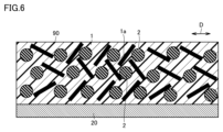
- FIG. 6 is a cross-sectional view schematically showing a laminate according to Comparative Example 1.
- the average value of the distance between the barycentric coordinates is less than 0.5 ⁇ m, so the distance between the particles of the inorganic filler 2 is sufficiently ensured. It is considered that this is because the molecular axis 1a of the liquid crystal polymer 1 located between the inorganic fillers 2 is prevented from being oriented along the in-plane direction D of the main surface of the film.
- the liquid crystal polymer film according to an embodiment of the present disclosure is a liquid crystal polymer film containing a liquid crystal polymer and an inorganic filler, and has a dielectric constant of 5 or more and 10 or less, and has a relative dielectric constant of 5 or more and 10 or less,
- the average value of the distance between the center of gravity coordinates of filler particles is 0.5 ⁇ m or more and 2.0 ⁇ m or less. According to the above configuration, a certain distance between the inorganic fillers is ensured in the liquid crystal polymer film. Therefore, the inorganic filler is not locally densely present.
- this embodiment includes the following disclosures.
- a liquid crystal polymer film comprising a liquid crystal polymer and an inorganic filler, The relative dielectric constant is 5 or more and 10 or less, A liquid crystal polymer film, wherein the average value of the distance between the barycentric coordinates of the particles of the inorganic filler in the liquid crystal polymer film is 0.5 ⁇ m or more and 2.0 ⁇ m or less.
- ⁇ 5> The liquid crystal polymer film according to any one of ⁇ 1> to ⁇ 4>, wherein the ratio of the content of the inorganic filler to the total content of the liquid crystal polymer and the inorganic filler is 20 vol% or more and 30 vol% or less.
- ⁇ 6> The liquid crystal polymer film according to any one of ⁇ 1> to ⁇ 5>, wherein the inorganic filler has an average particle size of 0.5 ⁇ m or more and 1.5 ⁇ m or less.
- the conductor layer is copper foil, The laminate according to ⁇ 7>, wherein the amount of warpage is 10 mm or less.
- ⁇ 9> The method for producing the liquid crystal polymer film according to any one of ⁇ 1> to ⁇ 6>, A dispersion step of obtaining a paste-like or slurry-like mixture by dispersing the liquid crystal polymer powder and the inorganic filler in a dispersion medium; a matting step of drying the paste-like or slurry-like mixture to form a mixture mat; A method for producing a liquid crystal polymer film, comprising: hot pressing the mixture mat to obtain the liquid crystal polymer film.
- the liquid crystal polymer powder includes liquid crystal polymer fibers that are fibrous particles made of the liquid crystal polymer, The method for producing a liquid crystal polymer film according to ⁇ 9>, wherein the average diameter of the liquid crystal polymer fibers is 1.4 ⁇ m or less.
- liquid crystal polymer 1 liquid crystal polymer, 1a molecular axis, 2 inorganic filler, 10, 90 liquid crystal polymer film, 20 conductor layer, 100 laminate.
Landscapes
- Chemical & Material Sciences (AREA)
- Engineering & Computer Science (AREA)
- Materials Engineering (AREA)
- Organic Chemistry (AREA)
- Crystallography & Structural Chemistry (AREA)
- Manufacturing & Machinery (AREA)
- Health & Medical Sciences (AREA)
- Chemical Kinetics & Catalysis (AREA)
- Medicinal Chemistry (AREA)
- Polymers & Plastics (AREA)
- Mechanical Engineering (AREA)
- Compositions Of Macromolecular Compounds (AREA)
- Manufacture Of Macromolecular Shaped Articles (AREA)
Priority Applications (3)
| Application Number | Priority Date | Filing Date | Title |
|---|---|---|---|
| JP2023576093A JP7639951B2 (ja) | 2022-08-03 | 2023-06-14 | 液晶ポリマーフィルムおよびこれを備えた積層体、ならびに、液晶ポリマーフィルムの製造方法 |
| CN202380014874.XA CN118355060A (zh) | 2022-08-03 | 2023-06-14 | 液晶聚合物膜和具备其的层叠体以及液晶聚合物膜的制造方法 |
| US18/623,431 US12617908B2 (en) | 2022-08-03 | 2024-04-01 | Liquid crystal polymer film, laminated body including the liquid crystal polymer film, and method of producing liquid crystal polymer film |
Applications Claiming Priority (2)
| Application Number | Priority Date | Filing Date | Title |
|---|---|---|---|
| JP2022-123967 | 2022-08-03 | ||
| JP2022123967 | 2022-08-03 |
Related Child Applications (1)
| Application Number | Title | Priority Date | Filing Date |
|---|---|---|---|
| US18/623,431 Continuation US12617908B2 (en) | 2022-08-03 | 2024-04-01 | Liquid crystal polymer film, laminated body including the liquid crystal polymer film, and method of producing liquid crystal polymer film |
Publications (1)
| Publication Number | Publication Date |
|---|---|
| WO2024029207A1 true WO2024029207A1 (ja) | 2024-02-08 |
Family
ID=89849267
Family Applications (1)
| Application Number | Title | Priority Date | Filing Date |
|---|---|---|---|
| PCT/JP2023/022058 Ceased WO2024029207A1 (ja) | 2022-08-03 | 2023-06-14 | 液晶ポリマーフィルムおよびこれを備えた積層体、ならびに、液晶ポリマーフィルムの製造方法 |
Country Status (3)
| Country | Link |
|---|---|
| JP (1) | JP7639951B2 (https=) |
| CN (1) | CN118355060A (https=) |
| WO (1) | WO2024029207A1 (https=) |
Citations (7)
| Publication number | Priority date | Publication date | Assignee | Title |
|---|---|---|---|---|
| JPH01311172A (ja) * | 1988-06-10 | 1989-12-15 | Nippon Petrochem Co Ltd | 電子レンジ用サセプター |
| JPH0841247A (ja) * | 1994-07-28 | 1996-02-13 | Otsuka Chem Co Ltd | 電子部品用樹脂組成物 |
| JP2003342431A (ja) * | 2002-05-28 | 2003-12-03 | Matsushita Electric Works Ltd | 熱可塑性樹脂組成物及び成形品 |
| JP2003342478A (ja) * | 2002-05-28 | 2003-12-03 | Matsushita Electric Works Ltd | 熱可塑性樹脂組成物及び成形品 |
| JP2004338393A (ja) * | 2003-04-22 | 2004-12-02 | Nippon Carbide Ind Co Inc | 多層樹脂金属積層体、及びその製造方法 |
| CN106928660A (zh) * | 2015-12-30 | 2017-07-07 | 广东生益科技股份有限公司 | 一种含填料的复合材料、片材以及含有它的电路基板 |
| WO2021177402A1 (ja) * | 2020-03-06 | 2021-09-10 | 株式会社村田製作所 | 液晶ポリマーフィルムおよびその製造方法 |
-
2023
- 2023-06-14 WO PCT/JP2023/022058 patent/WO2024029207A1/ja not_active Ceased
- 2023-06-14 CN CN202380014874.XA patent/CN118355060A/zh active Pending
- 2023-06-14 JP JP2023576093A patent/JP7639951B2/ja active Active
Patent Citations (7)
| Publication number | Priority date | Publication date | Assignee | Title |
|---|---|---|---|---|
| JPH01311172A (ja) * | 1988-06-10 | 1989-12-15 | Nippon Petrochem Co Ltd | 電子レンジ用サセプター |
| JPH0841247A (ja) * | 1994-07-28 | 1996-02-13 | Otsuka Chem Co Ltd | 電子部品用樹脂組成物 |
| JP2003342431A (ja) * | 2002-05-28 | 2003-12-03 | Matsushita Electric Works Ltd | 熱可塑性樹脂組成物及び成形品 |
| JP2003342478A (ja) * | 2002-05-28 | 2003-12-03 | Matsushita Electric Works Ltd | 熱可塑性樹脂組成物及び成形品 |
| JP2004338393A (ja) * | 2003-04-22 | 2004-12-02 | Nippon Carbide Ind Co Inc | 多層樹脂金属積層体、及びその製造方法 |
| CN106928660A (zh) * | 2015-12-30 | 2017-07-07 | 广东生益科技股份有限公司 | 一种含填料的复合材料、片材以及含有它的电路基板 |
| WO2021177402A1 (ja) * | 2020-03-06 | 2021-09-10 | 株式会社村田製作所 | 液晶ポリマーフィルムおよびその製造方法 |
Also Published As
| Publication number | Publication date |
|---|---|
| JP7639951B2 (ja) | 2025-03-05 |
| CN118355060A (zh) | 2024-07-16 |
| US20240247116A1 (en) | 2024-07-25 |
| JPWO2024029207A1 (https=) | 2024-02-08 |
Similar Documents
| Publication | Publication Date | Title |
|---|---|---|
| JP7260054B2 (ja) | 液晶ポリマーフィルムおよびその製造方法 | |
| JP7127746B2 (ja) | 樹脂シート及び樹脂多層基板 | |
| WO2003082977A1 (en) | Resin containing dielectric filler for formation of built-in capacitor layer of printed wiring board, copper double clad laminate having dielectric layer formed with resin containing dielectric filler, and process for producing copper double clad laminate | |
| US11365353B2 (en) | Black liquid-crystal polymer film and multilayer board | |
| JP2004035917A (ja) | 金属材表面への誘電体フィラー含有ポリイミド被膜の形成方法並びにプリント配線板用のキャパシタ層形成用の銅張積層板の製造方法及びその製造方法で得られた銅張積層板 | |
| CN113179611A (zh) | 氮化硼散热膜及其制备方法和应用 | |
| KR20220055453A (ko) | 액정 폴리에스테르 수지 조성물, 적층체, 액정 폴리에스테르 수지 필름 및 그의 제조 방법 | |
| CN114258343A (zh) | 电介质片的制造方法、高频印刷布线板用基板的制造方法、电介质片及高频印刷布线板用基板 | |
| JP7639951B2 (ja) | 液晶ポリマーフィルムおよびこれを備えた積層体、ならびに、液晶ポリマーフィルムの製造方法 | |
| US20250092605A1 (en) | Liquid crystal polymer powder, liquid crystal polymer film, and method of producing same | |
| US12617908B2 (en) | Liquid crystal polymer film, laminated body including the liquid crystal polymer film, and method of producing liquid crystal polymer film | |
| WO2023032376A1 (ja) | 液晶ポリマーフィルムおよび液晶ポリマーフィルムの製造方法 | |
| US20260091571A1 (en) | Laminated film and method for producing laminated film | |
| WO2022220079A1 (ja) | 繊維マットの製造方法、および繊維マット | |
| TWI853221B (zh) | 片狀銀粉及其製造方法和導電膏 | |
| JP7673839B2 (ja) | 液晶ポリマーペレット、液晶ポリマーパウダー、液晶ポリマーフィルム、および、それらの製造方法 | |
| WO2022259753A1 (ja) | 液晶ポリマーウェブの製造方法 | |
| CN118043185A (zh) | 成型体和成型体的制造方法 | |
| WO2024176534A1 (ja) | フッ素樹脂シート、その製造方法及びこれを含む金属張フッ素樹脂基板 |
Legal Events
| Date | Code | Title | Description |
|---|---|---|---|
| ENP | Entry into the national phase |
Ref document number: 2023576093 Country of ref document: JP Kind code of ref document: A |
|
| 121 | Ep: the epo has been informed by wipo that ep was designated in this application |
Ref document number: 23849767 Country of ref document: EP Kind code of ref document: A1 |
|
| WWE | Wipo information: entry into national phase |
Ref document number: 202380014874.X Country of ref document: CN |
|
| NENP | Non-entry into the national phase |
Ref country code: DE |
|
| 122 | Ep: pct application non-entry in european phase |
Ref document number: 23849767 Country of ref document: EP Kind code of ref document: A1 |