WO2024024643A1 - 画像形成装置 - Google Patents
画像形成装置 Download PDFInfo
- Publication number
- WO2024024643A1 WO2024024643A1 PCT/JP2023/026677 JP2023026677W WO2024024643A1 WO 2024024643 A1 WO2024024643 A1 WO 2024024643A1 JP 2023026677 W JP2023026677 W JP 2023026677W WO 2024024643 A1 WO2024024643 A1 WO 2024024643A1
- Authority
- WO
- WIPO (PCT)
- Prior art keywords
- input
- voice
- control unit
- instruction
- image forming
- Prior art date
- Legal status (The legal status is an assumption and is not a legal conclusion. Google has not performed a legal analysis and makes no representation as to the accuracy of the status listed.)
- Ceased
Links
Images



Classifications
-
- G—PHYSICS
- G03—PHOTOGRAPHY; CINEMATOGRAPHY; ANALOGOUS TECHNIQUES USING WAVES OTHER THAN OPTICAL WAVES; ELECTROGRAPHY; HOLOGRAPHY
- G03G—ELECTROGRAPHY; ELECTROPHOTOGRAPHY; MAGNETOGRAPHY
- G03G15/00—Apparatus for electrographic processes using a charge pattern
- G03G15/50—Machine control of apparatus for electrographic processes using a charge pattern, e.g. regulating differents parts of the machine, multimode copiers, microprocessor control
- G03G15/5016—User-machine interface; Display panels; Control console
-
- B—PERFORMING OPERATIONS; TRANSPORTING
- B41—PRINTING; LINING MACHINES; TYPEWRITERS; STAMPS
- B41J—TYPEWRITERS; SELECTIVE PRINTING MECHANISMS, i.e. MECHANISMS PRINTING OTHERWISE THAN FROM A FORME; CORRECTION OF TYPOGRAPHICAL ERRORS
- B41J29/00—Details of, or accessories for, typewriters or selective printing mechanisms not otherwise provided for
- B41J29/42—Scales and indicators, e.g. for determining side margins
-
- G—PHYSICS
- G03—PHOTOGRAPHY; CINEMATOGRAPHY; ANALOGOUS TECHNIQUES USING WAVES OTHER THAN OPTICAL WAVES; ELECTROGRAPHY; HOLOGRAPHY
- G03G—ELECTROGRAPHY; ELECTROPHOTOGRAPHY; MAGNETOGRAPHY
- G03G15/00—Apparatus for electrographic processes using a charge pattern
- G03G15/50—Machine control of apparatus for electrographic processes using a charge pattern, e.g. regulating differents parts of the machine, multimode copiers, microprocessor control
-
- G—PHYSICS
- G03—PHOTOGRAPHY; CINEMATOGRAPHY; ANALOGOUS TECHNIQUES USING WAVES OTHER THAN OPTICAL WAVES; ELECTROGRAPHY; HOLOGRAPHY
- G03G—ELECTROGRAPHY; ELECTROPHOTOGRAPHY; MAGNETOGRAPHY
- G03G15/00—Apparatus for electrographic processes using a charge pattern
- G03G15/50—Machine control of apparatus for electrographic processes using a charge pattern, e.g. regulating differents parts of the machine, multimode copiers, microprocessor control
- G03G15/5016—User-machine interface; Display panels; Control console
- G03G15/502—User-machine interface; Display panels; Control console relating to the structure of the control menu, e.g. pop-up menus, help screens
-
- G—PHYSICS
- G03—PHOTOGRAPHY; CINEMATOGRAPHY; ANALOGOUS TECHNIQUES USING WAVES OTHER THAN OPTICAL WAVES; ELECTROGRAPHY; HOLOGRAPHY
- G03G—ELECTROGRAPHY; ELECTROPHOTOGRAPHY; MAGNETOGRAPHY
- G03G21/00—Arrangements not provided for by groups G03G13/00 - G03G19/00, e.g. cleaning, elimination of residual charge
-
- G—PHYSICS
- G03—PHOTOGRAPHY; CINEMATOGRAPHY; ANALOGOUS TECHNIQUES USING WAVES OTHER THAN OPTICAL WAVES; ELECTROGRAPHY; HOLOGRAPHY
- G03G—ELECTROGRAPHY; ELECTROPHOTOGRAPHY; MAGNETOGRAPHY
- G03G21/00—Arrangements not provided for by groups G03G13/00 - G03G19/00, e.g. cleaning, elimination of residual charge
- G03G21/16—Mechanical means for facilitating the maintenance of the apparatus, e.g. modular arrangements
- G03G21/1604—Arrangement or disposition of the entire apparatus
- G03G21/1614—Measures for handling of apparatus by disabled persons
-
- H—ELECTRICITY
- H04—ELECTRIC COMMUNICATION TECHNIQUE
- H04N—PICTORIAL COMMUNICATION, e.g. TELEVISION
- H04N1/00—Scanning, transmission or reproduction of documents or the like, e.g. facsimile transmission; Details thereof
-
- G—PHYSICS
- G03—PHOTOGRAPHY; CINEMATOGRAPHY; ANALOGOUS TECHNIQUES USING WAVES OTHER THAN OPTICAL WAVES; ELECTROGRAPHY; HOLOGRAPHY
- G03G—ELECTROGRAPHY; ELECTROPHOTOGRAPHY; MAGNETOGRAPHY
- G03G2215/00—Apparatus for electrophotographic processes
- G03G2215/00025—Machine control, e.g. regulating different parts of the machine
- G03G2215/00122—Machine control, e.g. regulating different parts of the machine using speech synthesis or voice recognition
-
- Y—GENERAL TAGGING OF NEW TECHNOLOGICAL DEVELOPMENTS; GENERAL TAGGING OF CROSS-SECTIONAL TECHNOLOGIES SPANNING OVER SEVERAL SECTIONS OF THE IPC; TECHNICAL SUBJECTS COVERED BY FORMER USPC CROSS-REFERENCE ART COLLECTIONS [XRACs] AND DIGESTS
- Y02—TECHNOLOGIES OR APPLICATIONS FOR MITIGATION OR ADAPTATION AGAINST CLIMATE CHANGE
- Y02D—CLIMATE CHANGE MITIGATION TECHNOLOGIES IN INFORMATION AND COMMUNICATION TECHNOLOGIES [ICT], I.E. INFORMATION AND COMMUNICATION TECHNOLOGIES AIMING AT THE REDUCTION OF THEIR OWN ENERGY USE
- Y02D10/00—Energy efficient computing, e.g. low power processors, power management or thermal management
Definitions
- the present invention relates to an image forming apparatus capable of giving voice instructions.
- Some image forming apparatuses such as copying machines and multifunction peripherals, are equipped with an operation panel for users to perform manual input operations. By operating the operation panel, the user can select one function from a plurality of functions (for example, copy function, scanner function, facsimile function) or make settings for the function.
- functions for example, copy function, scanner function, facsimile function
- Patent Document 1 listed below describes that the contents of voice instructions are reflected in job settings
- Patent Document 2 listed below describes how to select a user from among a plurality of pieces of jib history information based on keywords included in the user's voice. This document describes how to narrow down the intended job history information.
- Patent Documents 1 and 2 do not disclose any means for solving the problem during voice input.
- the present invention has been made in view of the above circumstances, and an object of the present invention is to make it possible to ensure security and input accuracy when uttering and inputting voice for voice instructions.
- An image forming apparatus is an image forming apparatus that includes an image forming section that forms an image on a recording medium, and includes a display section, a display control section that displays an operation screen on the display section, and a user an operation unit into which manual input instructions are input by manual operation, a voice input unit into which voice is input from the user, a reception desk that receives voice instructions based on the voice input to the voice input unit, and the manual input instructions. and a control unit that controls the operation of the image forming apparatus to execute a job based on the manual input instruction and the voice instruction received by the reception unit, and the control unit is configured to receive the manual input instruction and the voice instruction.
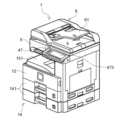
- FIG. 1 is a perspective view showing the appearance of an image forming apparatus according to an embodiment of the present invention.
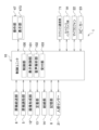
- 1 is a functional block diagram schematically showing the main internal configuration of an image forming apparatus.
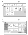
- (A) and (B) are diagrams showing an example of an operation screen displayed on a display unit.
- (A) and (B) are diagrams showing an example of an operation screen displayed on a display unit.
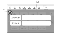
- FIG. 3 is a diagram showing an example of an operation screen displayed on a display unit.
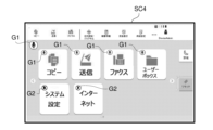
- FIG. 3 is a diagram showing an example of an operation screen displayed on a display unit.
- FIG. 3 is a diagram showing an example of an operation screen displayed on a display unit.
- 3 is a flowchart illustrating an example of processing performed by a control unit of an image forming apparatus.
- FIG. 3 is a diagram showing an example of an operation screen displayed on a display unit.
- FIG. 1 is a perspective view showing the appearance of an image forming apparatus according to an embodiment of the present invention.
- FIG. 2 is a functional block diagram schematically showing the main internal configuration of the image forming apparatus.
- the image forming apparatus 1 is a multifunction device that has multiple functions such as a copy function, a printer function, a scanner function, and a facsimile function, and includes a document feeding section 6, a document reading section 5, , an image forming section 12, a fixing section 13, a paper feeding section 14, a storage section 8, a motion sensor 21, an operation section 47, a facsimile communication section 71, a network interface section 91, a microphone 22, and a speaker 23.
- a document feeding section 6 a document reading section 5
- an image forming section 12 a fixing section 13
- a paper feeding section 14 a storage section 8
- a motion sensor 21 an operation section 47
- a facsimile communication section 71 a network interface section 91
- microphone 22 and a speaker 23.
- the document feeding section 6 is configured to be openable and closable by a hinge (not shown) on the top surface of the document reading section 5, and the document feeding section 6 is configured to be able to open and close the document placed on a platen glass (not shown). Functions as a holding cover.
- the document feeding unit 6 is also called an ADF (Auto Document Feeder) or a DP (Document Processor), and is equipped with a document placement tray 61, and transfers the document placed on the document placement tray 61 to the document reading unit. 5. Supply one sheet at a time.
- the original reading unit 5 optically reads the image of the original supplied to the original reading unit 5 by the original feeding unit 6 or placed on the platen glass, and generates image data.
- the image data generated by the document reading section 5 is stored in an unillustrated image memory or the like.
- the image forming section 12 Based on the image data generated by the document reading operation or the image data received from a computer as an external device (for example, a personal computer) connected to a network, the image forming section 12 generates a recording sheet fed from the paper feeding section 14. A toner image is formed on recording paper as a medium.
- the fixing unit 13 heats and presses the recording paper on which the toner image has been formed by the image forming unit 12 to fix the toner image on the recording paper. It is discharged at 51.
- the paper feed section 14 includes a plurality of paper feed cassettes 141.
- the storage unit 8 is a large capacity storage device such as an HDD (Hard Disk Drive) or an SSD (Solid State Drive), and stores various control programs and the like.
- HDD Hard Disk Drive
- SSD Solid State Drive
- the human sensor 21 detects a person approaching the image forming apparatus 1.
- a sensor that detects infrared rays emitted by a human body is used.
- the operation unit 47 receives instructions from the operator regarding various operations and processes that can be executed by the image forming apparatus 1, such as an instruction to execute an image forming operation.
- the operation unit 47 includes a display unit 473 that displays operation guidance for the operator.
- the operation unit 47 also receives instructions from the user via the touch panel included in the display unit 473 based on the user's operation (touch operation) on the operation screen displayed on the display unit 473 or the user's operation on the physical keys. Accept input.
- the display section 473 consists of an LCD (Liquid Crystal Display) or the like.
- the display section 473 includes a touch panel. When the operator performs an operation of touching a button or key displayed on the screen, the touch panel receives an instruction associated with the position of the touch operation.
- the facsimile communication unit 71 includes an unillustrated encoding/decoding unit, modulation/demodulation unit, and NCU (Network Control Unit), and performs facsimile transmission and reception using a public telephone line or the like.
- the network interface unit 91 is a communication interface that sends and receives various data to and from devices (for example, a personal computer) within the local area or on the Internet.
- the microphone 22 collects sounds around the image forming apparatus 1 and converts them into electrical signals (audio data). Note that the microphone 22 is provided at a suitable location where it is easy to collect the voice uttered by the user, for example, at the operation unit 47.
- the speaker 23 outputs various sounds, such as operation sounds and sound effects when operating the operation unit 47, dance sounds explaining the operation method, and warning sounds when a trouble occurs in the image forming apparatus 1.
- the speaker 23 is provided at a location that is not visible from the outside of the image forming apparatus 1, for example, within the operation section 47.
- the control unit 10 is configured to include a processor, a RAM (Random Access Memory), a ROM (Read Only Memory), and a dedicated hardware circuit.
- the processor is, for example, a CPU (Central Processing Unit), an ASIC (Application Specific Integrated Circuit), or an MPU (Micro Processing Unit).
- the control unit 10 includes a control section 100, a display control section 101, a voice analysis section 102, and a reception section 103.
- the control unit 10 functions as a control section 100, a display control section 101, an audio analysis section 102, and a reception section 103 by the operation of the processor according to a control program stored in the storage section 8.
- these control sections 100 and the like may be configured by hardware circuits without depending on the operation according to the control program by the control unit 10.
- the control unit 100 controls the overall operation of the image forming apparatus 1.
- the control section 100 includes a document feeding section 6, a document reading section 5, an image forming section 12, a fixing section 13, a paper feeding section 14, a storage section 8, a human sensor 21, an operation section 47, a facsimile communication section 71, and a network interface. 91, the microphone 22, and the speaker 23, and controls the driving of these respective parts.
- the control unit 100 controls the operation of the image forming unit 12 and the like to form a document image obtained by reading by the document reading unit 5 on recording paper as a recording medium.
- the control unit 100 controls the microphone 22 to turn on, enables audio input to the microphone 22, and the human sensor 21 detects the approaching person.
- a predetermined period of time for example, 30 seconds
- the microphone 22 is controlled to be turned off.
- the control unit 100 can also turn on and off the microphone 22 in accordance with an instruction input to the operation unit 47.
- the display control unit 101 controls the display on the display unit 473.
- the display control unit 101 displays a selection screen on the display unit 473 for allowing the user to select a function to be executed from among a plurality of functions executable by the image forming apparatus 1, and also displays a selection screen from the selection screen.
- Display unit 473 displays a setting screen for accepting input related to setting of each function, which is also a lower layer.
- FIGS. 3A and 3B are diagrams showing examples of screens displayed on the display section 473.
- the operation screen SC1 shown in FIG. 3A is a selection screen for allowing the user to select a function to be executed from among a plurality of functions executable by the image forming apparatus 1.
- the operation screen SC1 displays a "copy” button, a “send (scanner function)” button, a “fax (facsimile function)” button, and the like. Note that the operation screen SC1 as the selection screen is also a "home” screen.
- the control unit 100 displays the operation screen SC2 shown in FIG. 3(B) on the display unit 473 in accordance with this instruction.
- the operation screen SC2 is displayed on the display section 473 as a lower hierarchy than the "home” screen.
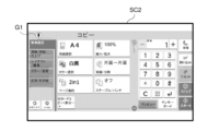
- the operation screen SC2 is a setting screen for accepting input related to settings of the "copy” function.
- "Copy” function "Paper selection”, “Color selection”, “Page consolidation”, “Reduction/Enlargement”, “Duplex/Split”, and “Staple/Punch” are written.
- Six buttons will be displayed. These buttons are images for accepting settings related to the "copy” function.
- a symbol G1 whose design is a microphone is displayed on the operation screen SC1 shown in FIG. 3(A) and the operation screen SC2 shown in FIG. 3(B) (top left in FIGS. 3(A) and (B)).
- the display of the symbol G1 indicates that voice input to the microphone 22 is possible. That is, the control unit 100 displays the symbol G1 on the operation screen SC2 when the microphone 22 is turned on and the microphone 22 is in a state where voice input is possible.
- control unit 100 when the control unit 100 turns off the microphone 22 and disables voice input, the control unit 100 displays the operation screen SC1 and On the operation screen SC2 (top left in FIGS. 3A and 3B), a symbol G2 is displayed, which is an image of an "x" superimposed on a symbol G1 whose design is a microphone.
- the speech analysis unit 102 converts the electrical signal (speech data) converted by the microphone 22 into text data using existing speech recognition technology, and analyzes the text data using existing natural language processing technology. , recognize voice instructions from the user.
- the reception unit 103 receives an instruction input by manual input operation via the operation unit 47 (including a touch panel) on the screen currently displayed on the display unit 473 and a voice recognized by the voice analysis unit 102 via the microphone 22.
- the instruction (analysis result by the voice analysis unit 102) is received as an instruction from the user.
- the control unit 100 executes the job according to the contents of the instruction received by the reception unit 103.
- the display control unit 101 displays on the display unit 473 a setting screen that displays the instructions input by manual input operation or the content indicated by the audio instructions. For example, when the operation screen SC2 as the setting screen shown in FIG. ” to “black and white” and “page aggregation” to “2in1” are input, and the reception unit 103 receives these instructions. At this time, the display control unit 101 changes the "paper selection” setting from “auto” to "A4", the "color selection” setting from “full color” to “black and white”, and the "page The display section 473 displays an operation screen SC2 (setting screen) in which "Aggregation” is switched from “Off” to "2in1".
- the display control section 101 displays an operation screen SC2 as shown in FIG. 6 on the display section 473.
- the control unit 100 operates in a manual input only mode in which only manual input instructions input by operating the operation unit 47 are accepted by the reception unit 103, and in a voice input enabled mode in which the voice instructions and the manual input instructions are accepted by the reception unit 103. Switch between.
- the control unit 100 sets the manual input only mode so that the reception unit 103 does not accept voice instructions. (i) Turns off the microphone 22 so that only manual input instructions are accepted by the reception unit 103. or (ii) prevent the reception unit 103 from accepting a voice instruction in which voice is input to the microphone 22 in the on state and the voice is analyzed by the voice analysis unit 102. good.
- the control unit 100 switches to the manual input only mode when the display control unit 101 displays on the display unit 473 an operation screen for accepting input of information for which input by voice instruction is prohibited in advance.
- Information that is previously prohibited from being input using voice instructions is, for example, taboo content that is not likely to be leaked (e.g., user ID or password), and/or information that does not maintain accuracy with voice input and cannot provide accurate instructions.
- This is predetermined voice input prohibition information, such as instruction contents that cannot be input (for example, an email address to send an email to, an IP address to send data to, etc.).
- voice input prohibition information such as instruction contents that cannot be input (for example, an email address to send an email to, an IP address to send data to, etc.).
- the display control unit 101 When the display control unit 101 is switched to the voice input enabled mode, the display control unit 101 causes the operation screen displayed on the display unit 473 to display an image or message indicating that voice instructions are accepted. On the other hand, when the display control unit 101 is switched to the manual input only mode, the display control unit 101 causes the operation screen displayed on the display unit 473 to display an image or a message indicating that the voice instruction cannot be accepted.
- the control unit 100 switches the operation mode of the image forming apparatus 1 to a manual input only mode,
- the reception unit 103 does not accept voice instructions regarding the user ID and password, but only accepts manual input operations.
- the display control unit 101 displays a symbol G2 on the authentication screen SC3, which is a symbol of a microphone with an "X" superimposed thereon, indicating that these operation targets do not accept voice instructions.
- the authentication screen SC3 may be displayed when performing system settings other than when logging in. Further, when performing private printing, a password is required to be input, and a similar authentication screen SC3 is displayed in this case as well.
- control unit 10 of the image forming apparatus 1 will be described based on the flowchart shown in FIG. 8. Note that this process is performed when the operation screen displayed on the display unit 473 is switched. Note that, as an initial setting, the control unit 100 switches the operation mode of the image forming apparatus 1 to a voice input enabled mode.
- the control unit 100 determines whether the switched operation screen is an operation screen for accepting input of the voice input prohibition information (S1). .
- control unit 100 determines that the operation screen after table switching is an operation screen for accepting input of the voice input prohibition information (S1 "Yes")
- the control unit 100 changes the operation mode of the image forming apparatus 1.
- the reception unit 103 does not accept voice instructions for the user ID and password, but only accepts manual input operations.
- the display control unit 101 causes the operation screen to display an image or message indicating that the voice instruction cannot be accepted, as shown in the example in FIG. 7 (S3).
- control unit 100 determines that the operation screen after table switching is not an operation screen for accepting the input of the voice input prohibition information (S1 "No")
- the control unit 100 changes the operation mode of the image forming apparatus 1 to the voice input prohibition information.
- the input enabled mode remains (S4). After this, the process ends.
- the operation screen for accepting the input of the voice input prohibition information for example, private information (confidential information) such as a user ID or password
- the reception screen is displayed on the display unit 473. Since the section 103 does not accept voice instructions but only manual input instructions, the user does not have to say personal information such as a user ID or password, making it possible to prevent leakage of confidential information and ensure security. become.
- the display unit 473 displays an operation screen for accepting destination information for data transmission, such as an e-mail address to which the email is to be sent, an IP address to which the data is to be sent, etc., as the voice input prohibition information
- the reception is Since the unit 103 does not accept voice instructions but only manual input instructions, the user must input the destination information by manually operating the operation unit 47, and the destination information (instruction content) The accuracy of input is maintained, and information (instructions) can be input accurately.
- the display control unit 101 may display, on the operation screen of the display unit 473, both input items that accept voice instructions and input items that accept only manual input instructions (for example, the display control unit 101 displays the input items that accept only manual input instructions). Operation screen SC1). When displaying such an operation screen on the display unit 473, the display control unit 101 displays an input item that only accepts manual input instructions with an image or message indicating that voice input is not accepted.
- the symbol G1 of a microphone is displayed, and on the other hand, the "System Settings" and “Internet” buttons that do not accept voice instructions are displayed with the symbol G1 of a microphone as an image indicating that they do not accept voice input.
- a symbol G2 with "x" superimposed on it is displayed.
- the control unit 100 switches the operation mode of the image forming apparatus 1 to a voice input enabled mode. Based on the content of the audio information inputted from the audio analysis unit 102, the receiving unit 103 performs a process of not accepting audio instructions indicating audio input prohibition information, but accepting audio instructions other than audio input prohibition information.
- the control unit 100 stores the total number of voice instructions and manual input instructions received by the reception unit 103. Then, when the operation screen to be the initial screen is displayed on the display unit 473 by the display control unit 101, the control unit 100 selects the manual input only mode or the voice input mode, whichever has the larger total number of receptions. mode, the operation mode of the image forming apparatus 1 is switched to this mode.
- the reception unit 103 does not accept voice instructions for inputting voice input prohibition information, but only accepts manual input instructions. This allows users to switch to the mode they frequently use when displaying the initial screen, improving convenience while ensuring the security and accuracy of input information. Become.
- the audio data collected by the microphone 22 and converted is analyzed by the audio analysis unit 102 in the image forming apparatus 1
- a device called a smart speaker A speaker with a built-in microphone and an AI (artificial intelligence) assistant function is adopted, the user's voice is collected by the speaker, and the image forming apparatus 1 uses the speaker as an audio input unit to analyze the audio from the speaker.
- the receiving unit 103 may receive the results.
- the present invention is not limited to the configuration of the above embodiments, and various modifications are possible. Further, in the embodiment described above, the configuration and processing shown in the embodiment using FIGS. 1 to 9 are merely one embodiment of the present invention, and the present invention is not intended to be limited to the configuration and processing.
Landscapes
- Physics & Mathematics (AREA)
- General Physics & Mathematics (AREA)
- Engineering & Computer Science (AREA)
- Microelectronics & Electronic Packaging (AREA)
- Human Computer Interaction (AREA)
- Multimedia (AREA)
- Signal Processing (AREA)
- Facsimiles In General (AREA)
- Control Or Security For Electrophotography (AREA)
- Accessory Devices And Overall Control Thereof (AREA)
- User Interface Of Digital Computer (AREA)
Priority Applications (6)
| Application Number | Priority Date | Filing Date | Title |
|---|---|---|---|
| CN202380014082.2A CN118120220A (zh) | 2022-07-29 | 2023-07-20 | 图像形成装置 |
| US18/705,168 US12474658B2 (en) | 2022-07-29 | 2023-07-20 | Image forming apparatus that controls of receiving and not receiving voice instruction in voice input possible mode |
| EP23846374.9A EP4564797A4 (en) | 2022-07-29 | 2023-07-20 | IMAGE FORMATION DEVICE |
| JP2024537655A JP7655451B2 (ja) | 2022-07-29 | 2023-07-20 | 画像形成装置 |
| JP2025039508A JP7835325B2 (ja) | 2022-07-29 | 2025-03-12 | 画像形成装置 |
| JP2026037919A JP2026091858A (ja) | 2022-07-29 | 2026-03-10 | 画像形成装置 |
Applications Claiming Priority (2)
| Application Number | Priority Date | Filing Date | Title |
|---|---|---|---|
| JP2022121285 | 2022-07-29 | ||
| JP2022-121285 | 2022-07-29 |
Publications (1)
| Publication Number | Publication Date |
|---|---|
| WO2024024643A1 true WO2024024643A1 (ja) | 2024-02-01 |
Family
ID=89706444
Family Applications (1)
| Application Number | Title | Priority Date | Filing Date |
|---|---|---|---|
| PCT/JP2023/026677 Ceased WO2024024643A1 (ja) | 2022-07-29 | 2023-07-20 | 画像形成装置 |
Country Status (5)
| Country | Link |
|---|---|
| US (1) | US12474658B2 (cg-RX-API-DMAC7.html) |
| EP (1) | EP4564797A4 (cg-RX-API-DMAC7.html) |
| JP (3) | JP7655451B2 (cg-RX-API-DMAC7.html) |
| CN (1) | CN118120220A (cg-RX-API-DMAC7.html) |
| WO (1) | WO2024024643A1 (cg-RX-API-DMAC7.html) |
Citations (6)
| Publication number | Priority date | Publication date | Assignee | Title |
|---|---|---|---|---|
| JP2007079852A (ja) * | 2005-09-13 | 2007-03-29 | Canon Inc | データ処理装置、データ処理方法及びコンピュータプログラム |
| JP2007333778A (ja) * | 2006-06-12 | 2007-12-27 | Toshiichi Shinshi | 商品売買システムとそれを実現するためのコンピュータプログラムとその方法 |
| JP2014196847A (ja) * | 2013-03-29 | 2014-10-16 | パナソニック株式会社 | 冷蔵庫 |
| JP2016126704A (ja) * | 2015-01-08 | 2016-07-11 | コニカミノルタ株式会社 | 情報処理装置、入力手段選択方法、およびコンピュータプログラム |
| JP2019205052A (ja) | 2018-05-23 | 2019-11-28 | コニカミノルタ株式会社 | ジョブ履歴特定装置、画像処理装置、サーバー、ジョブ履歴特定方法及びプログラム |
| JP2020098383A (ja) | 2018-12-17 | 2020-06-25 | コニカミノルタ株式会社 | 情報処理装置及びプログラム |
Family Cites Families (5)
| Publication number | Priority date | Publication date | Assignee | Title |
|---|---|---|---|---|
| JP3437509B2 (ja) * | 1998-10-09 | 2003-08-18 | キヤノン株式会社 | 画像形成装置並びに音声により指示可能な画像形成装置の制御方法および記憶媒体 |
| JP7230482B2 (ja) * | 2018-12-17 | 2023-03-01 | コニカミノルタ株式会社 | 画像処理システム、画像形成装置、音声入力禁止判定方法及びプログラム |
| JP7192477B2 (ja) * | 2018-12-18 | 2022-12-20 | コニカミノルタ株式会社 | 画像形成装置、画像形成装置の制御方法およびプログラム |
| JP7430034B2 (ja) * | 2019-04-26 | 2024-02-09 | シャープ株式会社 | 画像形成装置、画像形成方法及びプログラム |
| JP7415350B2 (ja) * | 2019-07-08 | 2024-01-17 | コニカミノルタ株式会社 | 音声操作システム、制御装置、および制御プログラム |
-
2023
- 2023-07-20 WO PCT/JP2023/026677 patent/WO2024024643A1/ja not_active Ceased
- 2023-07-20 EP EP23846374.9A patent/EP4564797A4/en active Pending
- 2023-07-20 JP JP2024537655A patent/JP7655451B2/ja active Active
- 2023-07-20 US US18/705,168 patent/US12474658B2/en active Active
- 2023-07-20 CN CN202380014082.2A patent/CN118120220A/zh active Pending
-
2025
- 2025-03-12 JP JP2025039508A patent/JP7835325B2/ja active Active
-
2026
- 2026-03-10 JP JP2026037919A patent/JP2026091858A/ja active Pending
Patent Citations (6)
| Publication number | Priority date | Publication date | Assignee | Title |
|---|---|---|---|---|
| JP2007079852A (ja) * | 2005-09-13 | 2007-03-29 | Canon Inc | データ処理装置、データ処理方法及びコンピュータプログラム |
| JP2007333778A (ja) * | 2006-06-12 | 2007-12-27 | Toshiichi Shinshi | 商品売買システムとそれを実現するためのコンピュータプログラムとその方法 |
| JP2014196847A (ja) * | 2013-03-29 | 2014-10-16 | パナソニック株式会社 | 冷蔵庫 |
| JP2016126704A (ja) * | 2015-01-08 | 2016-07-11 | コニカミノルタ株式会社 | 情報処理装置、入力手段選択方法、およびコンピュータプログラム |
| JP2019205052A (ja) | 2018-05-23 | 2019-11-28 | コニカミノルタ株式会社 | ジョブ履歴特定装置、画像処理装置、サーバー、ジョブ履歴特定方法及びプログラム |
| JP2020098383A (ja) | 2018-12-17 | 2020-06-25 | コニカミノルタ株式会社 | 情報処理装置及びプログラム |
Non-Patent Citations (1)
| Title |
|---|
| See also references of EP4564797A4 |
Also Published As
| Publication number | Publication date |
|---|---|
| JP7655451B2 (ja) | 2025-04-02 |
| EP4564797A1 (en) | 2025-06-04 |
| JP2025090755A (ja) | 2025-06-17 |
| EP4564797A4 (en) | 2026-07-22 |
| CN118120220A (zh) | 2024-05-31 |
| JP2026091858A (ja) | 2026-06-04 |
| JPWO2024024643A1 (cg-RX-API-DMAC7.html) | 2024-02-01 |
| US12474658B2 (en) | 2025-11-18 |
| JP7835325B2 (ja) | 2026-03-25 |
| US20250028268A1 (en) | 2025-01-23 |
Similar Documents
| Publication | Publication Date | Title |
|---|---|---|
| US11055042B2 (en) | Image forming apparatus and method for controlling image forming apparatus | |
| JP7210937B2 (ja) | 画像形成装置 | |
| JP5459260B2 (ja) | 画像形成装置、設定方法および設定プログラム | |
| JP2025092678A (ja) | 画像形成装置 | |
| JP7835325B2 (ja) | 画像形成装置 | |
| JPWO2024024641A5 (cg-RX-API-DMAC7.html) | ||
| JP6579005B2 (ja) | タッチ式入力装置、画像形成装置およびタッチ式入力装置の制御方法 | |
| US9699333B2 (en) | Image forming system including a portable terminal device | |
| JP6354696B2 (ja) | 表示装置、および画像処理装置 | |
| JPWO2024024643A5 (cg-RX-API-DMAC7.html) | ||
| JP7655452B2 (ja) | 画像形成装置 | |
| JP7694835B2 (ja) | 画像形成装置 | |
| JP5454436B2 (ja) | 表示処理装置およびコンピュータプログラム | |
| JP7363129B2 (ja) | 電子機器及び画像形成装置 | |
| JPWO2024024644A5 (cg-RX-API-DMAC7.html) | ||
| JP2008271047A (ja) | 画像読取装置 | |
| JP2008301104A (ja) | 画像形成装置および電子機器 | |
| JPWO2024024642A5 (cg-RX-API-DMAC7.html) | ||
| JP6314815B2 (ja) | 機能選択装置、および画像処理装置 | |
| JP2015191242A (ja) | 電子機器及び表示制御プログラム | |
| JP2008172482A (ja) | 画像形成装置 |
Legal Events
| Date | Code | Title | Description |
|---|---|---|---|
| 121 | Ep: the epo has been informed by wipo that ep was designated in this application |
Ref document number: 23846374 Country of ref document: EP Kind code of ref document: A1 |
|
| WWE | Wipo information: entry into national phase |
Ref document number: 2024537655 Country of ref document: JP |
|
| WWE | Wipo information: entry into national phase |
Ref document number: 202380014082.2 Country of ref document: CN |
|
| WWE | Wipo information: entry into national phase |
Ref document number: 18705168 Country of ref document: US |
|
| WWE | Wipo information: entry into national phase |
Ref document number: 2023846374 Country of ref document: EP |
|
| NENP | Non-entry into the national phase |
Ref country code: DE |
|
| ENP | Entry into the national phase |
Ref document number: 2023846374 Country of ref document: EP Effective date: 20250228 |
|
| WWP | Wipo information: published in national office |
Ref document number: 2023846374 Country of ref document: EP |
|
| WWG | Wipo information: grant in national office |
Ref document number: 18705168 Country of ref document: US |