WO2024024302A1 - 負極及び二次電池 - Google Patents
負極及び二次電池 Download PDFInfo
- Publication number
- WO2024024302A1 WO2024024302A1 PCT/JP2023/021741 JP2023021741W WO2024024302A1 WO 2024024302 A1 WO2024024302 A1 WO 2024024302A1 JP 2023021741 W JP2023021741 W JP 2023021741W WO 2024024302 A1 WO2024024302 A1 WO 2024024302A1
- Authority
- WO
- WIPO (PCT)
- Prior art keywords
- negative electrode
- layer
- current collector
- active material
- electrode active
- Prior art date
- Legal status (The legal status is an assumption and is not a legal conclusion. Google has not performed a legal analysis and makes no representation as to the accuracy of the status listed.)
- Ceased
Links
Images


Classifications
-
- H—ELECTRICITY
- H01—ELECTRIC ELEMENTS
- H01M—PROCESSES OR MEANS, e.g. BATTERIES, FOR THE DIRECT CONVERSION OF CHEMICAL ENERGY INTO ELECTRICAL ENERGY
- H01M4/00—Electrodes
- H01M4/02—Electrodes composed of, or comprising, active material
- H01M4/13—Electrodes for accumulators with non-aqueous electrolyte, e.g. for lithium-accumulators; Processes of manufacture thereof
- H01M4/134—Electrodes based on metals, Si or alloys
-
- H—ELECTRICITY
- H01—ELECTRIC ELEMENTS
- H01M—PROCESSES OR MEANS, e.g. BATTERIES, FOR THE DIRECT CONVERSION OF CHEMICAL ENERGY INTO ELECTRICAL ENERGY
- H01M10/00—Secondary cells; Manufacture thereof
- H01M10/05—Accumulators with non-aqueous electrolyte
- H01M10/052—Li-accumulators
-
- H—ELECTRICITY
- H01—ELECTRIC ELEMENTS
- H01M—PROCESSES OR MEANS, e.g. BATTERIES, FOR THE DIRECT CONVERSION OF CHEMICAL ENERGY INTO ELECTRICAL ENERGY
- H01M10/00—Secondary cells; Manufacture thereof
- H01M10/05—Accumulators with non-aqueous electrolyte
- H01M10/052—Li-accumulators
- H01M10/0525—Rocking-chair batteries, i.e. batteries with lithium insertion or intercalation in both electrodes; Lithium-ion batteries
-
- H—ELECTRICITY
- H01—ELECTRIC ELEMENTS
- H01M—PROCESSES OR MEANS, e.g. BATTERIES, FOR THE DIRECT CONVERSION OF CHEMICAL ENERGY INTO ELECTRICAL ENERGY
- H01M4/00—Electrodes
- H01M4/02—Electrodes composed of, or comprising, active material
- H01M4/36—Selection of substances as active materials, active masses, active liquids
- H01M4/38—Selection of substances as active materials, active masses, active liquids of elements or alloys
-
- H—ELECTRICITY
- H01—ELECTRIC ELEMENTS
- H01M—PROCESSES OR MEANS, e.g. BATTERIES, FOR THE DIRECT CONVERSION OF CHEMICAL ENERGY INTO ELECTRICAL ENERGY
- H01M4/00—Electrodes
- H01M4/02—Electrodes composed of, or comprising, active material
- H01M4/36—Selection of substances as active materials, active masses, active liquids
- H01M4/38—Selection of substances as active materials, active masses, active liquids of elements or alloys
- H01M4/386—Silicon or alloys based on silicon
-
- H—ELECTRICITY
- H01—ELECTRIC ELEMENTS
- H01M—PROCESSES OR MEANS, e.g. BATTERIES, FOR THE DIRECT CONVERSION OF CHEMICAL ENERGY INTO ELECTRICAL ENERGY
- H01M4/00—Electrodes
- H01M4/02—Electrodes composed of, or comprising, active material
- H01M4/64—Carriers or collectors
- H01M4/66—Selection of materials
-
- H—ELECTRICITY
- H01—ELECTRIC ELEMENTS
- H01M—PROCESSES OR MEANS, e.g. BATTERIES, FOR THE DIRECT CONVERSION OF CHEMICAL ENERGY INTO ELECTRICAL ENERGY
- H01M4/00—Electrodes
- H01M4/02—Electrodes composed of, or comprising, active material
- H01M4/64—Carriers or collectors
- H01M4/66—Selection of materials
- H01M4/661—Metal or alloys, e.g. alloy coatings
-
- H—ELECTRICITY
- H01—ELECTRIC ELEMENTS
- H01M—PROCESSES OR MEANS, e.g. BATTERIES, FOR THE DIRECT CONVERSION OF CHEMICAL ENERGY INTO ELECTRICAL ENERGY
- H01M4/00—Electrodes
- H01M4/02—Electrodes composed of, or comprising, active material
- H01M4/64—Carriers or collectors
- H01M4/66—Selection of materials
- H01M4/661—Metal or alloys, e.g. alloy coatings
- H01M4/662—Alloys
-
- H—ELECTRICITY
- H01—ELECTRIC ELEMENTS
- H01M—PROCESSES OR MEANS, e.g. BATTERIES, FOR THE DIRECT CONVERSION OF CHEMICAL ENERGY INTO ELECTRICAL ENERGY
- H01M4/00—Electrodes
- H01M4/02—Electrodes composed of, or comprising, active material
- H01M4/64—Carriers or collectors
- H01M4/66—Selection of materials
- H01M4/665—Composites
- H01M4/667—Composites in the form of layers, e.g. coatings
-
- H—ELECTRICITY
- H01—ELECTRIC ELEMENTS
- H01M—PROCESSES OR MEANS, e.g. BATTERIES, FOR THE DIRECT CONVERSION OF CHEMICAL ENERGY INTO ELECTRICAL ENERGY
- H01M4/00—Electrodes
- H01M4/02—Electrodes composed of, or comprising, active material
- H01M2004/026—Electrodes composed of, or comprising, active material characterised by the polarity
- H01M2004/027—Negative electrodes
-
- Y—GENERAL TAGGING OF NEW TECHNOLOGICAL DEVELOPMENTS; GENERAL TAGGING OF CROSS-SECTIONAL TECHNOLOGIES SPANNING OVER SEVERAL SECTIONS OF THE IPC; TECHNICAL SUBJECTS COVERED BY FORMER USPC CROSS-REFERENCE ART COLLECTIONS [XRACs] AND DIGESTS
- Y02—TECHNOLOGIES OR APPLICATIONS FOR MITIGATION OR ADAPTATION AGAINST CLIMATE CHANGE
- Y02E—REDUCTION OF GREENHOUSE GAS [GHG] EMISSIONS, RELATED TO ENERGY GENERATION, TRANSMISSION OR DISTRIBUTION
- Y02E60/00—Enabling technologies; Technologies with a potential or indirect contribution to GHG emissions mitigation
- Y02E60/10—Energy storage using batteries
Definitions
- the present disclosure relates to a negative electrode and a secondary battery.
- silicon is sometimes used as a main component as a negative electrode active material of a lithium ion secondary battery.
- silicon when silicon is used as the main component as the negative electrode active material of a lithium ion secondary battery, silicon absorbs lithium ions and expands during the first charging and discharging. Therefore, there was a risk that cycle characteristics would deteriorate due to cracks occurring in the negative electrode active material layer and peeling between the negative electrode active material layer and the negative electrode current collector.
- the present disclosure has been made in view of the above, and aims to provide a negative electrode and a secondary battery that can improve cycle characteristics.
- the negative electrode includes a negative electrode current collector, a negative electrode active material layer, a first layer provided between the negative electrode current collector and the negative electrode active material layer, and a first layer provided in the negative electrode active material layer.
- the negative electrode current collector contains at least one of copper, nickel, and iron
- the negative electrode active material layer contains silicon
- the first layer contains
- the second layer contains silicon, a metal element constituting the negative electrode current collector, and at least one of titanium, nickel, zinc, silver, iron, boron, indium, and germanium
- the second layer contains silicon, titanium, nickel, Contains at least one of zinc, silver, iron, boron, indium, and germanium.
- a secondary battery includes the negative electrode, a positive electrode, and an electrolyte.
- FIG. 1 is a schematic cross-sectional view showing an example of a secondary battery according to the first embodiment.
- FIG. 2 is a schematic cross-sectional view showing an example of a secondary battery according to the second embodiment.
- FIG. 3 is a schematic cross-sectional view showing an example of a secondary battery according to the third embodiment.
- FIG. 4 is a schematic enlarged view of area A in FIG.
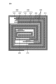
- FIG. 5 is a schematic cutaway diagram showing an example of the secondary battery according to the fourth embodiment.
- FIG. 6 is a schematic cross-sectional view taken along line VI-VI in FIG.
- FIG. 1 is a schematic cross-sectional view showing an example of a secondary battery according to the first embodiment.
- the secondary battery 1 in the first embodiment is an all-solid-state battery in which the electrolyte is solid, and is a lithium ion secondary battery.
- the secondary battery 1 includes a protective layer 10, a positive electrode 20, a negative electrode 30, a solid electrolyte layer 40, and an insulating layer 50.
- the secondary battery 1 has a structure in which a sheet-like positive electrode 20, a negative electrode 30, and a solid electrolyte layer 40 are stacked.
- the Z direction refers to the stacking direction of the positive electrode 20, the negative electrode 30, and the solid electrolyte layer 40
- the X direction refers to the direction perpendicular to the Z direction and parallel to the cross section of FIG.
- the Y direction refers to a direction perpendicular to the X direction and the Z direction.
- one of the X directions is sometimes described as the +X direction and the other as the ⁇ X direction.
- one of the Z directions may be described as +Z direction and the other as ⁇ Z direction.
- the protective layer 10 is a layer provided to physically and chemically protect the secondary battery 1.
- the protective layer 10 is provided so as to overlap the laminate of the positive electrode 20, the negative electrode 30, and the solid electrolyte layer 40 when viewed in plan in the Z direction, and in the example of FIG. 1, the positive electrode 20, the negative electrode 30, It is provided on both sides in the Z direction of the laminate with the solid electrolyte layer 40.
- the material of the protective layer 10 is not particularly limited as long as it is insulating, and examples thereof include resin, glass, and ceramics.
- the positive electrode 20 includes a positive electrode current collector layer 21 and a positive electrode active material layer 22.
- the positive electrode 20 has a structure in which the positive electrode active material layer 22 is laminated in the -Z direction of the positive electrode current collector layer 21, but this is just an example, and the positive electrode active material layer 22 is stacked in the +Z direction of the positive electrode current collector layer 21. They may be stacked in the same direction.
- the positive electrode current collector layer 21 is a layer that has conductivity.
- the end face of the positive electrode current collector layer 21 in the +X direction is exposed and can be connected to the outside. That is, the end face of the positive electrode current collector layer 21 in the +X direction serves as the positive electrode of the secondary battery 1.
- the material of the positive electrode current collector layer 21 is not particularly limited as long as it has conductivity, and examples thereof include metal materials such as silver, palladium, gold, platinum, aluminum, copper, and nickel, and carbon materials.
- the positive electrode active material layer 22 is a layer containing a positive electrode active material.
- the positive electrode active material layer 22 is laminated on the positive electrode current collector layer 21.
- the positive electrode active material is not particularly limited, and includes, for example, a lithium-containing phosphoric acid compound having a Nasicon-type structure, a lithium-containing phosphoric acid compound having an olivine-type structure, a lithium-containing layered oxide, and a lithium-containing oxide having a spinel-type structure. At least one type selected from the group consisting of:
- An example of a lithium-containing phosphoric acid compound having a Nasicon type structure includes Li 3 V 2 (PO 4 ) 3 and the like.
- lithium-containing phosphoric acid compounds having an olivine structure examples include Li 3 Fe 2 (PO 4 ) 3 and LiMnPO 4 .
- lithium-containing layered oxides include LiCoO 2 , LiCo 1/3 Ni 1/3 Mn 1/3 O 2 , and the like.
- lithium-containing oxides having a spinel structure examples include LiMn 2 O 4 , LiNi 0.5 Mn 1.5 O 4 , and the like.
- the material included in the positive electrode active material layer 22 is not limited to the positive electrode active material, and may also include a solid electrolyte and a sintering aid, which will be described later.
- the sintering aid is not particularly limited, and examples thereof include lithium oxide, sodium oxide, potassium oxide, boron oxide, silicon oxide, bismuth oxide, and phosphorus oxide.
- the negative electrode 30 includes a negative electrode current collector layer 31 , a peel prevention layer 32 , a negative electrode active material layer 33 , and a cap layer 34 .
- the negative electrode current collector layer 31 is a layer that has conductivity.
- the negative electrode current collector layer 31 is an example of a "negative electrode current collector.”
- the negative electrode current collector layer 31 has an exposed end face in the ⁇ X direction, and can be connected to the outside. That is, the end face of the negative electrode current collector layer 31 in the -X direction serves as the negative electrode of the secondary battery 1.
- the thickness of the negative electrode current collector layer 31 is not particularly limited, but is preferably thicker than the negative electrode active material layer 33 described later, and is approximately 30 ⁇ m.
- the material of the negative electrode current collector layer 31 is a conductive metal, and includes at least one metal selected from copper, nickel, and iron.
- the material of the negative electrode current collector layer 31 is not limited to this, and may further include a metal material such as palladium, gold, platinum, or aluminum. Further, the negative electrode current collector layer 31 is not limited to one layer, and may include a plurality of layers, such as stainless steel coated with nickel on the peel prevention layer 32 side, for example. In the following description, the material constituting the negative electrode current collector layer 31 may be referred to as a "negative electrode current collector material.”
- the anti-peeling layer 32 is a layer provided on the negative electrode current collector layer 31. Peeling prevention layer 32 is provided between negative electrode current collector layer 31 and negative electrode active material layer 33.
- the peel prevention layer 32 is an example of a "first layer”.
- the thickness of the peel prevention layer 32 is 5 nm or more and 55 nm or less. In the example of FIG. 1, the peel prevention layer 32 is provided in the +Z direction of the negative electrode current collector layer 31.
- the peel prevention layer 32 is made of silicon, negative electrode current collector material, titanium (Ti), nickel (Ni), zinc (Zn), silver (Ag), iron (Fe), boron (B), indium (In), and germanium. (Ge).
- the peel prevention layer 32 can suppress peeling between the negative electrode current collector layer 31 and the negative electrode active material layer 33 when the negative electrode active material layer 33 expands.
- the cycle characteristics of the secondary battery 1 can be improved.
- the element constituting the anti-peeling layer 32, excluding silicon and the negative electrode current collector material is preferably titanium. In this case, the resistance of the peel prevention layer 32 can be reduced.
- the elements constituting the anti-peeling layer 32, excluding silicon and the negative electrode current collector material may be referred to as the "first metal".
- the anti-peeling layer 32 contains silicon on the negative electrode active material layer 33 side. That is, silicon and the first metal are mixed on the side of the negative electrode active material layer 33 of the peel prevention layer 32.
- the concentration of silicon in the anti-peeling layer 32 is determined by XPS (X-ray Photoelectron Spectroscopy), AES (Auger Electron Spectroscopy), SIMS (Secondary Ion Mass). It can be measured by a composition analysis method in the depth direction such as spectrometry.
- the peel prevention layer 32 can suppress the interfacial energy with the negative electrode active material layer 33, and can further reduce the resistance between the negative electrode current collector layer 31 and the negative electrode active material layer 33.
- the peel prevention layer 32 does not contain silicon on the negative electrode current collector layer 31 side. That is, it can be said that the peel prevention layer 32 is a layer in which silicon is diffused only in the portion that contacts the negative electrode active material layer 33 in the thickness direction. Therefore, it can be said that the concentration of silicon contained in the peel prevention layer 32 on the negative electrode active material layer 33 side is higher than the silicon concentration contained in the peel prevention layer 32 on the negative electrode current collector layer 31 side.
- the peel prevention layer 32 includes a negative electrode current collector material on the negative electrode current collector layer 31 side. That is, on the side of the negative electrode current collector layer 31 of the peel prevention layer 32, the negative electrode current collector material and the first metal are mixed.
- the concentration of the negative electrode current collector material in the peel prevention layer 32 can be measured by a composition analysis method in the depth direction such as XPS, AES, SIMS, etc.
- the peel prevention layer 32 can suppress the interfacial energy with the negative electrode current collector layer 31, and can further reduce the resistance between the negative electrode current collector layer 31 and the negative electrode active material layer 33.
- the peel prevention layer 32 does not include a negative electrode current collector material on the negative electrode active material layer 33 side.
- the peel prevention layer 32 is a layer in which the negative electrode current collector material is diffused only in the portion that contacts the negative electrode current collector layer 31 in the thickness direction. Therefore, the concentration of the negative electrode current collector material contained in the negative electrode current collector layer 31 side of the peel prevention layer 32 is higher than the concentration of the negative electrode current collector material contained in the negative electrode active material layer 33 side of the peel prevention layer 32. It can be said that
- the negative electrode active material layer 33 is a layer containing a negative electrode active material.
- the negative electrode active material layer 33 is provided in the +Z direction of the peel prevention layer 32.
- the thickness of the negative electrode active material layer 33 is 2 ⁇ m or more and 5 ⁇ m or less. Thereby, the capacity of the secondary battery 1 can be improved.
- the negative electrode active material layer 33 contains silicon as a negative electrode active material.
- the crystallinity of silicon is not particularly limited, and may be amorphous, for example.
- the negative electrode active material is doped silicon.
- the dopant element for silicon in the negative electrode active material at least one element selected from boron, phosphorus (P), aluminum, bismuth (Bi), lithium (Li), and oxygen (O) can be used. Thereby, it is possible to suppress a decrease in the capacity of the secondary battery 1 due to the dopant.
- the cap layer 34 is a layer provided on the negative electrode active material layer 33.
- the cap layer 34 is an example of a "second layer".
- the cap layer 34 is provided in the +Z direction of the negative electrode active material layer 33.
- the thickness of the cap layer 34 is 5 nm or more and 55 nm or less.
- the cap layer 34 is made of silicon and at least one of titanium (Ti), nickel (Ni), zinc (Zn), silver (Ag), iron (Fe), boron (B), indium (In), and germanium (Ge). Contains more than one type. Thereby, the cap layer 34 has malleability. Therefore, even when the thickness of the negative electrode active material layer 33 is set to 2 ⁇ m or more, the stress generated by the expansion of the negative electrode active material layer 33 is applied to the cap layer 34, which has malleability and is difficult to crack. Therefore, generation of cracks in the negative electrode active material layer 33 can be suppressed. Therefore, damage to the negative electrode active material layer 33 can be suppressed, so that the cycle characteristics of the secondary battery 1 can be improved.
- the cap layer 34 is deformed so as to be pressed against the solid electrolyte layer 40, so that the cap layer 34 and the solid electrolyte layer 40 are in close contact with each other, and the cap layer 34 and the solid electrolyte layer 40 are in close contact with each other.
- the interfacial resistance with layer 40 can be reduced.
- the element constituting the cap layer 34 other than silicon is preferably titanium. Thereby, the resistance of the cap layer 34 can be reduced.
- the elements constituting the cap layer 34 excluding silicon are preferably the same as the elements constituting the peel prevention layer 32 excluding silicon and the negative electrode current collector material. Thereby, the stress of the negative electrode 30 can be uniformly relaxed.
- the elements constituting the cap layer 34 other than silicon may be referred to as "second metals.”
- the cap layer 34 contains silicon throughout its thickness. Thereby, the cap layer 34 can further reduce the interfacial resistance with the solid electrolyte layer 40. Further, it is preferable that the concentration of the second metal in the cap layer 34 decreases as it approaches the negative electrode active material layer 33. That is, it is preferable that the cap layer 34 has a silicon concentration gradient in the thickness direction, and the closer it is to the negative electrode active material layer 33, the higher the silicon concentration is.
- the silicon concentration of the cap layer 34 can be measured by a composition analysis in the depth direction using XPS, AES, SIMS, or the like.
- the stress in the cap layer 34 changes continuously in the Z direction, so it is possible to further suppress the generation of cracks due to the stress in the negative electrode active material layer 33. Further, since the concentration of the second metal changes continuously in the direction of the negative electrode active material layer 33, the interfacial energy between the cap layer 34 and the negative electrode active material layer 33 can be suppressed, and the interfacial energy between the cap layer 34 and the negative electrode active material layer The interfacial resistance with 33 can be reduced.
- the silicon concentration in the cap layer 34 is not limited to having a gradient in the thickness direction, and may be uniform.
- the configuration of the negative electrode 30 is not limited to the above.
- the negative electrode 30 has a structure in which a peel prevention layer 32, a negative electrode active material layer 33, and a cap layer 34 are laminated in the +Z direction of the negative electrode current collector layer 31. This is just an example, and the layers may be stacked in the -Z direction of the negative electrode current collector layer 31.
- Solid electrolyte layer 40 is a layer provided between positive electrode 20 and negative electrode 30.
- the solid electrolyte layer 40 is a sintered body containing a solid electrolyte.
- the material of the solid electrolyte is not particularly limited as long as it is a material that allows ions to move between the positive electrode 20 and the negative electrode 30.
- Examples of the solid electrolyte material include a lithium-containing phosphoric acid compound having a Nasicon structure, an oxide having a perovskite structure, and an oxide having a garnet type or garnet type similar structure.
- the lithium-containing phosphoric acid compound having a Nasicon structure is Li x My (PO 4 ) 3 (1 ⁇ x ⁇ 2, 1 ⁇ y ⁇ 2, M is at least one of Ti, Ge, Al, Ga, and Zr).
- An example of a lithium-containing phosphoric acid compound having a Nasicon structure includes, for example, Li 1.2 Al 0.2 Ti 1.8 (PO 4 ).
- Examples of oxides having a perovskite structure include La 0.55 Li 0.35 TiO 3 and the like.
- An example of an oxide having a garnet type or garnet type similar structure includes Li 7 La 3 Zr 2 O 12 and the like. Note that the material of the solid electrolyte layer 40 is not limited to the solid electrolyte, and may include the above-mentioned sintering aid.
- the side reinforcement portion 60 is provided to prevent short circuit of the secondary battery 1.
- the side reinforcement portions 60 are provided on the end faces of the positive electrode 20, the negative electrode 30, and the solid electrolyte layer 40 in the X direction and the Y direction.
- the material of the side reinforcement portion 60 is not particularly limited as long as it is an insulating material, and examples thereof include resin, glass, and ceramics.
- the negative electrode 30 has a negative electrode current collector (negative electrode current collector layer 31), a negative electrode active material layer 33, and a space between the negative electrode current collector and the negative electrode active material layer 33.
- the negative electrode current collector includes a first layer (peeling prevention layer 32) provided on the negative electrode active material layer 33 and a second layer (cap layer 34) provided on the negative electrode active material layer 33.
- the negative electrode active material layer 33 contains silicon, and the first layer contains silicon, the metal elements constituting the negative electrode current collector, titanium, nickel,
- the second layer contains silicon and at least one of titanium, nickel, zinc, silver, iron, boron, indium, and germanium. include.
- the second layer suppresses the generation of cracks in the negative electrode active material layer 33, and the negative electrode current collector and the negative electrode active material layer 33 are separated from each other. Since this can be suppressed by the first layer, the cycle maintenance rate can be improved.
- the elements constituting the first layer, excluding silicon and the metal constituting the negative electrode current collector are the same as the elements constituting the second layer, excluding silicon. Thereby, the stress of the negative electrode 30 can be uniformly relaxed.
- the element constituting the first layer excluding silicon and the metal constituting the negative electrode current collector is titanium
- the element constituting the second layer excluding silicon is titanium
- the concentration of silicon contained in the negative electrode active material layer side of the first layer is higher than the concentration of silicon contained in the negative electrode current collector side of the first layer, and The concentration of the negative electrode current collector material contained in the first layer is higher than the concentration of the negative electrode current collector material contained in the negative electrode active material layer 33 side of the first layer, and the second layer contains silicon throughout the thickness direction. . Thereby, the interfacial energy between the cap layer 34 and the negative electrode active material layer 33 can be further suppressed, and the interfacial resistance between the second layer and the negative electrode active material layer 33 can be further reduced.
- the interfacial energy with the negative electrode active material layer 33 can be further suppressed, and the negative electrode current collector The resistance between the negative electrode active material layer 33 and the negative electrode active material layer 33 can be further reduced.
- the concentration of the negative electrode current collector material in the first layer changes continuously in the direction in which the negative electrode current collector is provided, the interfacial energy with the negative electrode current collector can be further suppressed. The resistance between the electric body and the negative electrode active material layer 33 can be further reduced.
- the secondary battery 1 includes a positive electrode 20, a negative electrode 30, and an electrolyte (solid electrolyte layer 40). With this configuration, the cycle maintenance rate can be improved.
- the negative electrode 30 according to this embodiment is manufactured, for example, by the following method.
- a first metal layer, a silicon-containing layer, and a second metal layer are laminated on the negative electrode current collector layer 31 in this order.
- the lamination process is performed without contact with air, and is performed by, for example, sputtering, chemical vapor deposition, ion plating, or the like.
- the first metal layer is a layer made of a first metal, and has a thickness of 0.1 ⁇ m or more and 1 ⁇ m or less.
- the second metal layer is a layer made of a second metal, and has a thickness of 0.1 ⁇ m or more and 1 ⁇ m or less.
- a silicon-containing layer is a layer made of a silicon-containing material, for example a layer of a mixture of silicon and a dopant. In this case, silicon and the dopant are simultaneously deposited on the first metal layer and mixed.
- the laminate including the negative electrode current collector layer 31 is annealed.
- the silicon-containing layer becomes doped silicon
- the first metal of the first metal layer becomes the anti-peeling layer 32
- the second metal of the second metal layer diffuses into the silicon-containing layer to form the cap layer 34.
- Ru The annealing conditions are such that silicon is included throughout the thickness of the cap layer 34.
- a portion of the silicon-containing layer in which the first metal or the second metal has not diffused becomes the negative electrode active material layer 33.
- FIG. 2 is a schematic cross-sectional view showing an example of a secondary battery according to the second embodiment.
- the secondary battery according to this embodiment will be described below. Note that similar configurations are given the same reference numerals and explanations will be omitted.
- a secondary battery 1A according to the second embodiment is similar to the first embodiment and the second embodiment in that the negative electrode 30A includes a plurality of negative electrode active material layers 33a to 33d and a plurality of cap layers 34a to 34d. Different from secondary battery 1.
- the cap layers 34a to 34d are examples of "second layers". The thickness of each of the plurality of negative electrode active material layers 33a to 33d and the plurality of cap layers 34a to 34d is smaller than the thickness of the peel prevention layer 32.
- the negative electrode active material layers 33a to 33d and the cap layers 34a to 34d include the negative electrode active material layer 33d, the cap layer 34d, the negative electrode active material layer 33c, The cap layer 34c, the negative electrode active material layer 33b, the cap layer 34b, the negative electrode active material layer 33a, and the cap layer 34a are laminated in this order in the +Z direction of the peel prevention layer 32. That is, in the secondary battery 1A, it can be said that the cap layers 34a to 34d are alternately laminated with the negative electrode active material layers 33a to 33d in the Z direction.
- the cap layers 34b to 34d can suppress peeling of the negative electrode active material layers 33a to 33d, thereby improving the cycle characteristics of the secondary battery 1A.
- the second metal contained in the cap layers 34b to 34d acts as a surfactant (surfactant) for the silicon-containing layer in the production of the negative electrode 30A, so that the silicon-containing layer becomes thicker, so the secondary metal 1 can be improved. More specifically, in manufacturing the negative electrode 30A, the surface energy of the first silicon-containing layer is lowered by laminating the second metal layer on the silicon-containing layer, and the second silicon-containing layer laminated on the second metal layer reduces the surface energy of the first silicon-containing layer. Thickening of the layer is promoted.
- FIG. 3 is a schematic cross-sectional view showing an example of a secondary battery according to the third embodiment.
- the secondary battery 100 according to the third embodiment is a cylindrical battery and includes a liquid electrolyte.
- the secondary battery 200 includes a casing 110, a positive electrode 120, a negative electrode 130, and a separator 150.
- the casing 110 is a case that houses an electrode body and an electrolytic solution (not shown) therein.
- the casing 110 includes a battery can 111, a lid 112, a heat sensitive resistance element 113, a safety valve mechanism 114, a gasket 115, a positive lead 116, a negative lead 117, a center pin 119, an insulating plate 118, Equipped with.
- the battery can 111 is a cylindrical member that includes an end surface that becomes the negative electrode of the secondary battery 100. That is, the battery can 111 has a cylindrical shape with one end surface closed and the other end surface open.
- the battery can 111 is a conductor, and is made of, for example, an iron (Fe) base material whose surface is plated with nickel (Ni).
- the lid 112 is a disc-shaped member that includes a protrusion that becomes the positive electrode of the secondary battery 100.
- the lid body 112 is provided on the open end surface of the battery can 111.
- the lid 112 is made of metal, and is made of the same material as the battery can 111, for example.
- the direction in which the cylindrical portion of the battery can 111 extends is sometimes described as the longitudinal direction of the secondary battery 100.
- the positive electrode of the secondary battery 100 refers to the protrusion of the lid 112
- the negative electrode of the secondary battery 100 refers to the closed end surface of the battery can 111.
- the heat sensitive resistance element 113 is an element whose resistance increases as the temperature rises.
- the heat sensitive resistance element 113 is provided on the negative pole side with respect to the lid body 112.
- the heat-sensitive resistance element 113 increases its resistance value and limits the current when the secondary battery 100 becomes high temperature due to a short circuit or the like.
- the safety valve mechanism 114 is a mechanism whose shape changes depending on the gas pressure within the casing 110.
- the safety valve mechanism 114 is provided on the negative pole side with respect to the heat sensitive resistance element 113.
- the safety valve mechanism 114 is electrically connected to the lid 112 via the heat sensitive resistance element 113.
- the safety valve mechanism 114 has a projection on the negative electrode side, and when the gas pressure in the casing 110 is normal, it is in contact with the positive electrode lead 116 via the projection and is electrically connected.
- the safety valve mechanism 114 when the gas pressure inside the casing 110 increases, the protrusion reverses to the positive electrode side and separates from the positive electrode lead 116, thereby electrically disconnecting the positive electrode lead 116 and the lid 112.
- the gasket 115 is an annular member that fixes the lid 112, heat-sensitive resistance element 113, and safety valve mechanism 114 to the battery can 111.
- Gasket 115 is provided on the open end surface of battery can 111 .
- the gasket 115 brings the battery can 111 and the lid 112 into close contact with each other, making the inside of the casing 110 airtight.
- Gasket 115 is an insulator.
- the positive electrode lead 116 is a terminal connected to a positive electrode 120 of an electrode body described later.
- the positive electrode lead 116 is electrically connected to the lid 112 via the safety valve mechanism 114 and the heat sensitive resistance element 113.
- the positive electrode lead 116 is a conductor, and is made of aluminum (Al), for example.
- the negative electrode lead 117 is a terminal connected to a negative electrode 130 of an electrode body described later. Negative electrode lead 117 is electrically connected to battery can 111 .
- the negative electrode lead 117 is a conductor, and is made of nickel (Ni), for example.
- the insulating plate 118 is a plate-shaped member that is an insulator. Two insulating plates 118 are provided so as to cover a cross section of an electrode body, which will be described later, on the positive electrode side of the secondary battery 100 and a cross section on the negative electrode side of the secondary battery 100, respectively.
- the center pin 119 is provided at the central axis of the electrode body.
- the center pin 119 is a linear member having a length in the longitudinal direction of the secondary battery 100.
- the material of the center pin 119 is not particularly limited, and is, for example, metal.
- FIG. 4 is an enlarged view of area A in FIG. 3.
- a positive electrode 120 and a negative electrode 130 according to the third embodiment have a structure in which they are stacked with a separator 150 in between, and are provided inside a battery can 111.
- the positive electrode 120, the negative electrode 130, and the separator 150 are stacked in the radial direction of the secondary battery 100 with the center pin 119 as the center.
- the positive electrode 120 includes a positive electrode current collector layer 121 and a positive electrode active material layer 122.
- a positive electrode current collector layer 121 is stacked on two positive electrode active material layers 122.
- the material and thickness of the positive electrode current collector layer 121 are the same as those of the positive electrode current collector layer 21 in the first embodiment.
- the material and thickness of the positive electrode active material layer 122 are the same as those of the positive electrode active material layer 22 in the first embodiment.
- the negative electrode 130 includes a negative electrode current collector layer 131 and a negative electrode material layer 132.
- the negative electrode current collector layer 131 is an example of a "negative electrode current collector.”
- a negative electrode current collector layer 131 is laminated on two negative electrode material layers 132.
- the negative electrode current collector layer 131 is made of the same material as the negative electrode current collector layer 31 in the first embodiment.
- the negative electrode material layer 132 is a layer containing a negative electrode active material layer.
- the negative electrode material layer 132 includes a peel prevention layer, a negative electrode active material layer, and a cap layer, which are made of the same materials as in the first embodiment.
- the anti-peeling layer is an example of a "first layer” and the cap layer is an example of a "second layer.”
- the cap layer is a thinner layer than the anti-peeling layer.
- the negative electrode material layer 132 is a laminate in which a peel prevention layer, a negative electrode active material layer, and a cap layer are laminated in this order from the negative electrode current collector layer 131 side. Thereby, even if the negative electrode active material layer expands, since the peeling prevention layer is provided, peeling of the negative electrode material layer 132 from the negative electrode current collector layer 131 can be suppressed.
- the cycle characteristics of the secondary battery 100 can be improved.
- the separator 150 is a layer that insulates the positive electrode 120 and the negative electrode 130.
- the separator 150 is provided so that the positive electrode 120 and the negative electrode 130 do not come into direct contact with each other, and is laminated between the positive electrode 120 and the negative electrode 130 in the electrode body.
- the material of the separator 150 is preferably electrically stable, chemically stable with respect to the positive electrode active material, negative electrode active material, and electrolyte, and insulating.
- a layer made of a polymeric nonwoven fabric, a porous film, glass, or ceramic fibers can be used. More preferably, the material of separator 150 includes a porous polyolefin film.
- the separator 150 may be composed of a plurality of layers, and may be a composite of a porous polyolefin film and a heat-resistant membrane containing polyimide, glass, or ceramic fibers.
- the space surrounded by the insulating plate 118 and the battery can 111 is filled with electrolyte.
- the electrolyte includes an electrolyte salt and a solvent that dissolves the electrolyte salt.
- the electrolyte salt include lithium perchlorate (LiClO 4 ), lithium hexafluorophosphate (LiPF 6 ), lithium tetrafluoroborate (LiBF 4 ), and lithium bis(trifluoromethanesulfonyl)imide (LiN(SO 2 ).
- lithium bis(pentafluoroethanesulfonyl)imide LiN(SO 2 C 2 F 5 ) 2
- lithium hexafluoroarsenate LiAsF 6
- the solvent include lactone solvents such as ⁇ -butyrolactone, ⁇ -valerolactone, ⁇ -valerolactone, or ⁇ -caprolactone, ethylene carbonate, propylene carbonate, butylene carbonate, vinylene carbonate, dimethyl carbonate, ethylmethyl carbonate, or diethyl carbonate.
- carbonate ester solvents such as 1,2-dimethoxyethane, 1-ethoxy-2-methoxyethane, 1,2-diethoxyethane, tetrahydrofuran or 2-methyltetrahydrofuran, nitrile solvents such as acetonitrile, sulfolane
- ether solvents such as 1,2-dimethoxyethane, 1-ethoxy-2-methoxyethane, 1,2-diethoxyethane, tetrahydrofuran or 2-methyltetrahydrofuran
- nitrile solvents such as acetonitrile
- sulfolane non-aqueous solvents containing system solvents, phosphoric acids, phosphate ester solvents, pyrrolidones, and the like.
- FIG. 5 is a cutaway diagram showing an example of a secondary battery according to the fourth embodiment.
- FIG. 6 is a schematic cross-sectional view taken along line VI-VI in FIG.
- the secondary battery 200 according to the fourth embodiment includes a gel electrolyte.
- the secondary battery 200 according to the fourth embodiment includes a battery element, an exterior member 211, an adhesive material 212, a protective material 213, a positive electrode 220, a negative electrode 230, and a gel. It includes a shaped electrolyte layer 240, a separator 250, a positive electrode lead 260, and a negative electrode lead 270.
- the exterior member 211 is a case of the secondary battery 200.
- Exterior member 211 includes an insulating layer, a metal layer, and an outermost layer.
- the exterior member 211 has a structure in which an insulating layer, a metal layer, and an outermost layer are laminated in this order from the inside, and then bonded together by laminating or the like.
- the insulating layer of the exterior member 211 is made of, for example, resin such as polyethylene, polypropylene, modified polyethylene, modified polypropylene, or polyolefin resin containing ethylene or propylene as a monomer. Thereby, the exterior member 211 can lower moisture permeability of the secondary battery 200 and improve airtightness.
- the metal layer of the exterior member 211 is a plate or foil film made of metal such as aluminum, stainless steel, nickel, or iron.
- the outermost layer may be made of any material, but is preferably made of a material that has high strength against tearing, piercing, etc., such as the same resin as the insulating layer or nylon.
- the adhesive material 212 is a member for making the exterior member 211 airtight.
- Adhesive material 212 is provided between exterior member 211 and positive electrode lead 260 and negative electrode lead 270.
- the material of the adhesive material 212 preferably has adhesiveness to the positive electrode lead 260 and the negative electrode lead 270.
- the adhesive material 212 is made of polyolefin resin such as polyethylene, polypropylene, modified polyethylene, or modified polypropylene.
- the positive electrode 220 includes a positive electrode current collector layer 221 and a positive electrode active material layer 222.
- the material and thickness of the positive electrode current collector layer 221 are the same as those of the positive electrode current collector layer 21 in the first embodiment. Further, the material and thickness of the positive electrode active material layer 222 are the same as those of the positive electrode active material layer 22 in the first embodiment.
- the negative electrode 230 includes a negative electrode current collector layer 231 and a negative electrode material layer 232.
- the negative electrode current collector layer 131 is an example of a "negative electrode current collector.”
- the negative electrode current collector layer 131 includes a peel prevention layer, a negative electrode active material layer, and a cap layer, which are made of the same materials as in the first embodiment. That is, the anti-peeling layer is an example of a "first layer” and the cap layer is an example of a "second layer.” Here, the cap layer is a thinner layer than the anti-peeling layer.
- the negative electrode material layer 232 is a laminate in which a peel prevention layer, a negative electrode active material layer, and a cap layer are laminated in this order from the negative electrode current collector layer 231 side. ing.
- the peeling prevention layer is provided, peeling of the negative electrode material layer 132 from the negative electrode current collector layer 131 can be suppressed.
- the cap layer is provided, deterioration of the negative electrode active material due to electrolyte gel entering the cracks can be suppressed. Therefore, the cycle characteristics of the secondary battery 200 can be improved.
- the positive electrode 220, the negative electrode 230, the gel electrolyte layer 240, and the separator 250 have a structure in which they are wound around a positive electrode lead 260 and a negative electrode lead 270. From the outside, that is, from the protective material 213 side: negative electrode current collector layer 231, negative electrode material layer 232, gel electrolyte layer 240, separator 250, gel electrolyte layer 240, positive electrode active material layer 222, positive electrode current collector layer 221, positive electrode The active material layer 222, the gel electrolyte layer 240, the separator 250, the gel electrolyte layer 240, and the negative electrode material layer 232 are laminated in this order.
- the gel electrolyte layer 240 is a layer that becomes the electrolyte of the secondary battery 200.
- the gel electrolyte layer 240 is a gel layer made of a polymer compound that retains an electrolyte.
- any polymer compound can be used as long as it absorbs a solvent and becomes a gel.
- polyvinylidene fluoride or vinylidene fluoride, and hexane Fluorine-based polymer compounds such as copolymers with fluoropropylene, ether-based polymer compounds such as polyethylene oxide or crosslinked products containing polyethylene oxide, or polymer compounds containing polyacrylonitrile, polypropylene oxide, or polymethyl methacrylate as monomers, etc.
- the polymer compound used as the gel of the gel electrolyte layer 240 is preferably a fluorine-based polymer compound, and more preferably a copolymer containing vinylidene fluoride and hexafluoropropylene as monomers. By using this material, stability against redox reactions can be improved.
- the copolymers of high molecular compounds used as the gel of the gel electrolyte layer 240 include monoesters of unsaturated dibasic acids such as monomethyl maleate, halogenated ethylenes such as trifluorochloroethylene, and vinylene carbonate. It may further contain as a monomer a cyclic carbonate ester of an unsaturated compound such as or an epoxy group-containing acryl vinyl monomer. In this case, cycle characteristics can be improved.
- the positive electrode lead 260 is a terminal drawn out from the positive electrode current collector layer 221 to the outside of the exterior member 211. That is, the positive electrode lead 260 is a terminal that becomes the positive electrode of the secondary battery 200. In FIG. 6, the positive electrode lead 260 is provided near the center of the portion surrounded by the protective material 213. The material of the positive electrode lead 260 is the same as that of the positive electrode lead 116 in the third embodiment.
- the negative electrode lead 270 is a terminal drawn out from the negative electrode current collector layer 231 to the outside of the exterior member 211. That is, the negative electrode lead 270 is a terminal that becomes the negative electrode of the secondary battery 200. In FIG. 6, the negative electrode lead 270 is provided near the center of the portion surrounded by the protective material 213. The material of the negative electrode lead 270 is the same as that of the positive electrode lead 116 in the third embodiment.
- the protective material 213 is a member that protects the secondary battery 200.
- the protective material 213 is provided so as to wrap around the negative electrode 230.
- the protective material 213 is, for example, an insulating tape.
Landscapes
- Chemical & Material Sciences (AREA)
- Chemical Kinetics & Catalysis (AREA)
- Electrochemistry (AREA)
- General Chemical & Material Sciences (AREA)
- Engineering & Computer Science (AREA)
- Materials Engineering (AREA)
- Manufacturing & Machinery (AREA)
- Composite Materials (AREA)
- Battery Electrode And Active Subsutance (AREA)
- Secondary Cells (AREA)
Priority Applications (3)
| Application Number | Priority Date | Filing Date | Title |
|---|---|---|---|
| JP2024536832A JP7786590B2 (ja) | 2022-07-28 | 2023-06-12 | 負極及び二次電池 |
| CN202380051452.XA CN119404325A (zh) | 2022-07-28 | 2023-06-12 | 负极和二次电池 |
| US18/933,129 US20250054944A1 (en) | 2022-07-28 | 2024-10-31 | Negative electrode and secondary battery |
Applications Claiming Priority (2)
| Application Number | Priority Date | Filing Date | Title |
|---|---|---|---|
| JP2022120791 | 2022-07-28 | ||
| JP2022-120791 | 2022-07-28 |
Related Child Applications (1)
| Application Number | Title | Priority Date | Filing Date |
|---|---|---|---|
| US18/933,129 Continuation US20250054944A1 (en) | 2022-07-28 | 2024-10-31 | Negative electrode and secondary battery |
Publications (1)
| Publication Number | Publication Date |
|---|---|
| WO2024024302A1 true WO2024024302A1 (ja) | 2024-02-01 |
Family
ID=89706171
Family Applications (1)
| Application Number | Title | Priority Date | Filing Date |
|---|---|---|---|
| PCT/JP2023/021741 Ceased WO2024024302A1 (ja) | 2022-07-28 | 2023-06-12 | 負極及び二次電池 |
Country Status (4)
| Country | Link |
|---|---|
| US (1) | US20250054944A1 (https=) |
| JP (1) | JP7786590B2 (https=) |
| CN (1) | CN119404325A (https=) |
| WO (1) | WO2024024302A1 (https=) |
Citations (5)
| Publication number | Priority date | Publication date | Assignee | Title |
|---|---|---|---|---|
| JP2006059714A (ja) * | 2004-08-20 | 2006-03-02 | Sony Corp | 負極および電池 |
| JP2008153078A (ja) * | 2006-12-18 | 2008-07-03 | Sony Corp | 負極および電池 |
| JP2016521914A (ja) * | 2013-06-21 | 2016-07-25 | ハイドロ−ケベック | 高エネルギー電池用アノード |
| US20210336269A1 (en) * | 2020-04-28 | 2021-10-28 | Samsung Sdi Co., Ltd. | All-SOLID-STATE SECONDARY BATTERY |
| US20220045354A1 (en) * | 2020-08-06 | 2022-02-10 | Samsung Electronics Co., Ltd. | All-solid secondary battery and method of manufacturing the same |
-
2023
- 2023-06-12 WO PCT/JP2023/021741 patent/WO2024024302A1/ja not_active Ceased
- 2023-06-12 CN CN202380051452.XA patent/CN119404325A/zh active Pending
- 2023-06-12 JP JP2024536832A patent/JP7786590B2/ja active Active
-
2024
- 2024-10-31 US US18/933,129 patent/US20250054944A1/en active Pending
Patent Citations (5)
| Publication number | Priority date | Publication date | Assignee | Title |
|---|---|---|---|---|
| JP2006059714A (ja) * | 2004-08-20 | 2006-03-02 | Sony Corp | 負極および電池 |
| JP2008153078A (ja) * | 2006-12-18 | 2008-07-03 | Sony Corp | 負極および電池 |
| JP2016521914A (ja) * | 2013-06-21 | 2016-07-25 | ハイドロ−ケベック | 高エネルギー電池用アノード |
| US20210336269A1 (en) * | 2020-04-28 | 2021-10-28 | Samsung Sdi Co., Ltd. | All-SOLID-STATE SECONDARY BATTERY |
| US20220045354A1 (en) * | 2020-08-06 | 2022-02-10 | Samsung Electronics Co., Ltd. | All-solid secondary battery and method of manufacturing the same |
Also Published As
| Publication number | Publication date |
|---|---|
| US20250054944A1 (en) | 2025-02-13 |
| JPWO2024024302A1 (https=) | 2024-02-01 |
| CN119404325A (zh) | 2025-02-07 |
| JP7786590B2 (ja) | 2025-12-16 |
Similar Documents
| Publication | Publication Date | Title |
|---|---|---|
| JP5412937B2 (ja) | 非水電解質組成物及び非水電解質二次電池 | |
| KR101843577B1 (ko) | 비수 전해질 2차 전지 및 그 제조 방법 | |
| US11430994B2 (en) | Protective coatings for lithium metal electrodes | |
| JP4735579B2 (ja) | 非水電解質電池 | |
| US20090197158A1 (en) | Nonaqueous electrolyte battery | |
| JP5453709B2 (ja) | 電気化学デバイス用の外装材およびこれを用いた電気化学デバイス | |
| EP2950370A1 (en) | Lithium secondary battery | |
| US20220278316A1 (en) | Methods for prelithiation of silicon containing electrodes | |
| CN102623709B (zh) | 电池 | |
| CN108023092A (zh) | 包括电活性材料的电池组电池和电池组 | |
| JP6656370B2 (ja) | リチウムイオン二次電池および組電池 | |
| JP4970875B2 (ja) | 全固体蓄電素子 | |
| KR20170111636A (ko) | 파우치형 이차 전지 | |
| KR100812749B1 (ko) | 리튬 이차 전지용 양극, 이의 제조방법 및 이를 포함하는리튬 이차 전지 | |
| JP5261883B2 (ja) | 双極型二次電池 | |
| JP2019212571A (ja) | 二次電池 | |
| KR101744382B1 (ko) | 이차전지용 전극 리드 및 이를 포함하는 이차전지 | |
| JP7786590B2 (ja) | 負極及び二次電池 | |
| JP5181422B2 (ja) | 双極型二次電池 | |
| KR20230089412A (ko) | 음극/고체전해질 계면이 제어된 전고체 전지 및 이의 제조방법 | |
| JP2010021043A (ja) | セパレータ、セパレータの製造方法および電池 | |
| KR102821321B1 (ko) | 산화물계 고체전해질을 포함하는 전해질 복합체, 이의 제조방법 및 이를 포함하는 전고체전지 | |
| KR102782616B1 (ko) | 전극 조립체 및 이를 포함하는 이차 전지 | |
| JP4609707B2 (ja) | 電池 | |
| JP2006253087A (ja) | 高分子電解質およびそれを用いた電池 |
Legal Events
| Date | Code | Title | Description |
|---|---|---|---|
| 121 | Ep: the epo has been informed by wipo that ep was designated in this application |
Ref document number: 23846038 Country of ref document: EP Kind code of ref document: A1 |
|
| WWE | Wipo information: entry into national phase |
Ref document number: 2024536832 Country of ref document: JP |
|
| WWE | Wipo information: entry into national phase |
Ref document number: 202380051452.X Country of ref document: CN |
|
| WWP | Wipo information: published in national office |
Ref document number: 202380051452.X Country of ref document: CN |
|
| NENP | Non-entry into the national phase |
Ref country code: DE |
|
| 122 | Ep: pct application non-entry in european phase |
Ref document number: 23846038 Country of ref document: EP Kind code of ref document: A1 |