WO2024024302A1 - Negative electrode and secondary battery - Google Patents
Negative electrode and secondary battery Download PDFInfo
- Publication number
- WO2024024302A1 WO2024024302A1 PCT/JP2023/021741 JP2023021741W WO2024024302A1 WO 2024024302 A1 WO2024024302 A1 WO 2024024302A1 JP 2023021741 W JP2023021741 W JP 2023021741W WO 2024024302 A1 WO2024024302 A1 WO 2024024302A1
- Authority
- WO
- WIPO (PCT)
- Prior art keywords
- negative electrode
- layer
- current collector
- active material
- electrode active
- Prior art date
Links
- 239000007773 negative electrode material Substances 0.000 claims abstract description 108
- 239000010703 silicon Substances 0.000 claims abstract description 70
- 229910052710 silicon Inorganic materials 0.000 claims abstract description 70
- 229910052751 metal Inorganic materials 0.000 claims abstract description 43
- PXHVJJICTQNCMI-UHFFFAOYSA-N Nickel Chemical compound [Ni] PXHVJJICTQNCMI-UHFFFAOYSA-N 0.000 claims abstract description 42
- 239000002184 metal Substances 0.000 claims abstract description 42
- XEEYBQQBJWHFJM-UHFFFAOYSA-N Iron Chemical compound [Fe] XEEYBQQBJWHFJM-UHFFFAOYSA-N 0.000 claims abstract description 27
- 239000010936 titanium Substances 0.000 claims abstract description 20
- 229910052759 nickel Inorganic materials 0.000 claims abstract description 19
- 229910052719 titanium Inorganic materials 0.000 claims abstract description 17
- RTAQQCXQSZGOHL-UHFFFAOYSA-N Titanium Chemical compound [Ti] RTAQQCXQSZGOHL-UHFFFAOYSA-N 0.000 claims abstract description 16
- 229910052742 iron Inorganic materials 0.000 claims abstract description 12
- ZOXJGFHDIHLPTG-UHFFFAOYSA-N Boron Chemical compound [B] ZOXJGFHDIHLPTG-UHFFFAOYSA-N 0.000 claims abstract description 10
- BQCADISMDOOEFD-UHFFFAOYSA-N Silver Chemical compound [Ag] BQCADISMDOOEFD-UHFFFAOYSA-N 0.000 claims abstract description 10
- 229910052796 boron Inorganic materials 0.000 claims abstract description 10
- 229910052732 germanium Inorganic materials 0.000 claims abstract description 10
- 229910052709 silver Inorganic materials 0.000 claims abstract description 10
- 239000004332 silver Substances 0.000 claims abstract description 10
- GNPVGFCGXDBREM-UHFFFAOYSA-N germanium atom Chemical compound [Ge] GNPVGFCGXDBREM-UHFFFAOYSA-N 0.000 claims abstract description 9
- 229910052738 indium Inorganic materials 0.000 claims abstract description 9
- APFVFJFRJDLVQX-UHFFFAOYSA-N indium atom Chemical compound [In] APFVFJFRJDLVQX-UHFFFAOYSA-N 0.000 claims abstract description 9
- HCHKCACWOHOZIP-UHFFFAOYSA-N Zinc Chemical compound [Zn] HCHKCACWOHOZIP-UHFFFAOYSA-N 0.000 claims abstract description 7
- 229910052725 zinc Inorganic materials 0.000 claims abstract description 7
- 239000011701 zinc Substances 0.000 claims abstract description 7
- RYGMFSIKBFXOCR-UHFFFAOYSA-N Copper Chemical compound [Cu] RYGMFSIKBFXOCR-UHFFFAOYSA-N 0.000 claims abstract description 5
- 229910052802 copper Inorganic materials 0.000 claims abstract description 5
- 239000010949 copper Substances 0.000 claims abstract description 5
- XUIMIQQOPSSXEZ-UHFFFAOYSA-N Silicon Chemical compound [Si] XUIMIQQOPSSXEZ-UHFFFAOYSA-N 0.000 claims description 67
- 239000003792 electrolyte Substances 0.000 claims description 15
- 150000002739 metals Chemical class 0.000 claims description 2
- 239000000470 constituent Substances 0.000 claims 1
- 239000010410 layer Substances 0.000 description 388
- 239000000463 material Substances 0.000 description 59
- 230000002265 prevention Effects 0.000 description 36
- 239000007774 positive electrode material Substances 0.000 description 21
- 239000007784 solid electrolyte Substances 0.000 description 20
- -1 phosphoric acid compound Chemical class 0.000 description 19
- WHXSMMKQMYFTQS-UHFFFAOYSA-N Lithium Chemical compound [Li] WHXSMMKQMYFTQS-UHFFFAOYSA-N 0.000 description 12
- 229910052744 lithium Inorganic materials 0.000 description 12
- 239000011245 gel electrolyte Substances 0.000 description 11
- 150000001875 compounds Chemical class 0.000 description 10
- 229920000642 polymer Polymers 0.000 description 8
- 230000001681 protective effect Effects 0.000 description 8
- 235000011007 phosphoric acid Nutrition 0.000 description 7
- 239000000853 adhesive Substances 0.000 description 6
- 230000001070 adhesive effect Effects 0.000 description 6
- 229910052782 aluminium Inorganic materials 0.000 description 6
- 229910000147 aluminium phosphate Inorganic materials 0.000 description 6
- NBIIXXVUZAFLBC-UHFFFAOYSA-N phosphoric acid Substances OP(O)(O)=O NBIIXXVUZAFLBC-UHFFFAOYSA-N 0.000 description 6
- 239000002904 solvent Substances 0.000 description 6
- XAGFODPZIPBFFR-UHFFFAOYSA-N aluminium Chemical compound [Al] XAGFODPZIPBFFR-UHFFFAOYSA-N 0.000 description 5
- 239000000178 monomer Substances 0.000 description 5
- 239000011241 protective layer Substances 0.000 description 5
- HBBGRARXTFLTSG-UHFFFAOYSA-N Lithium ion Chemical compound [Li+] HBBGRARXTFLTSG-UHFFFAOYSA-N 0.000 description 4
- KDLHZDBZIXYQEI-UHFFFAOYSA-N Palladium Chemical compound [Pd] KDLHZDBZIXYQEI-UHFFFAOYSA-N 0.000 description 4
- 239000004698 Polyethylene Substances 0.000 description 4
- 239000004743 Polypropylene Substances 0.000 description 4
- 238000004833 X-ray photoelectron spectroscopy Methods 0.000 description 4
- 239000000919 ceramic Substances 0.000 description 4
- 239000002019 doping agent Substances 0.000 description 4
- 239000002223 garnet Substances 0.000 description 4
- 239000011521 glass Substances 0.000 description 4
- 229910001416 lithium ion Inorganic materials 0.000 description 4
- 239000000203 mixture Substances 0.000 description 4
- BASFCYQUMIYNBI-UHFFFAOYSA-N platinum Chemical compound [Pt] BASFCYQUMIYNBI-UHFFFAOYSA-N 0.000 description 4
- 229920000573 polyethylene Polymers 0.000 description 4
- 229920001155 polypropylene Polymers 0.000 description 4
- 230000002787 reinforcement Effects 0.000 description 4
- 229920005989 resin Polymers 0.000 description 4
- 239000011347 resin Substances 0.000 description 4
- 238000000682 scanning probe acoustic microscopy Methods 0.000 description 4
- WEVYAHXRMPXWCK-UHFFFAOYSA-N Acetonitrile Chemical compound CC#N WEVYAHXRMPXWCK-UHFFFAOYSA-N 0.000 description 3
- 238000004458 analytical method Methods 0.000 description 3
- 239000004020 conductor Substances 0.000 description 3
- 229920001577 copolymer Polymers 0.000 description 3
- 239000007789 gas Substances 0.000 description 3
- 238000004519 manufacturing process Methods 0.000 description 3
- 150000003839 salts Chemical class 0.000 description 3
- 238000005245 sintering Methods 0.000 description 3
- BQCIDUSAKPWEOX-UHFFFAOYSA-N 1,1-Difluoroethene Chemical compound FC(F)=C BQCIDUSAKPWEOX-UHFFFAOYSA-N 0.000 description 2
- VAYTZRYEBVHVLE-UHFFFAOYSA-N 1,3-dioxol-2-one Chemical compound O=C1OC=CO1 VAYTZRYEBVHVLE-UHFFFAOYSA-N 0.000 description 2
- YEJRWHAVMIAJKC-UHFFFAOYSA-N 4-Butyrolactone Chemical compound O=C1CCCO1 YEJRWHAVMIAJKC-UHFFFAOYSA-N 0.000 description 2
- RTZKZFJDLAIYFH-UHFFFAOYSA-N Diethyl ether Chemical compound CCOCC RTZKZFJDLAIYFH-UHFFFAOYSA-N 0.000 description 2
- XTHFKEDIFFGKHM-UHFFFAOYSA-N Dimethoxyethane Chemical compound COCCOC XTHFKEDIFFGKHM-UHFFFAOYSA-N 0.000 description 2
- VGGSQFUCUMXWEO-UHFFFAOYSA-N Ethene Chemical compound C=C VGGSQFUCUMXWEO-UHFFFAOYSA-N 0.000 description 2
- 229920003171 Poly (ethylene oxide) Polymers 0.000 description 2
- WYURNTSHIVDZCO-UHFFFAOYSA-N Tetrahydrofuran Chemical compound C1CCOC1 WYURNTSHIVDZCO-UHFFFAOYSA-N 0.000 description 2
- 238000000137 annealing Methods 0.000 description 2
- 230000007423 decrease Effects 0.000 description 2
- 230000006866 deterioration Effects 0.000 description 2
- 238000010586 diagram Methods 0.000 description 2
- 239000008151 electrolyte solution Substances 0.000 description 2
- 239000003759 ester based solvent Substances 0.000 description 2
- 239000000835 fiber Substances 0.000 description 2
- PCHJSUWPFVWCPO-UHFFFAOYSA-N gold Chemical compound [Au] PCHJSUWPFVWCPO-UHFFFAOYSA-N 0.000 description 2
- 229910052737 gold Inorganic materials 0.000 description 2
- 239000010931 gold Substances 0.000 description 2
- 239000012212 insulator Substances 0.000 description 2
- 150000002500 ions Chemical group 0.000 description 2
- 238000010030 laminating Methods 0.000 description 2
- 238000003475 lamination Methods 0.000 description 2
- 238000012423 maintenance Methods 0.000 description 2
- 239000007769 metal material Substances 0.000 description 2
- 238000000034 method Methods 0.000 description 2
- 229910052763 palladium Inorganic materials 0.000 description 2
- 150000003016 phosphoric acids Chemical class 0.000 description 2
- 229910052697 platinum Inorganic materials 0.000 description 2
- 229920000098 polyolefin Polymers 0.000 description 2
- 229920005672 polyolefin resin Polymers 0.000 description 2
- 229910001220 stainless steel Inorganic materials 0.000 description 2
- 239000010935 stainless steel Substances 0.000 description 2
- 239000004094 surface-active agent Substances 0.000 description 2
- JBQYATWDVHIOAR-UHFFFAOYSA-N tellanylidenegermanium Chemical compound [Te]=[Ge] JBQYATWDVHIOAR-UHFFFAOYSA-N 0.000 description 2
- ZZXUZKXVROWEIF-UHFFFAOYSA-N 1,2-butylene carbonate Chemical compound CCC1COC(=O)O1 ZZXUZKXVROWEIF-UHFFFAOYSA-N 0.000 description 1
- LZDKZFUFMNSQCJ-UHFFFAOYSA-N 1,2-diethoxyethane Chemical compound CCOCCOCC LZDKZFUFMNSQCJ-UHFFFAOYSA-N 0.000 description 1
- CAQYAZNFWDDMIT-UHFFFAOYSA-N 1-ethoxy-2-methoxyethane Chemical compound CCOCCOC CAQYAZNFWDDMIT-UHFFFAOYSA-N 0.000 description 1
- JWUJQDFVADABEY-UHFFFAOYSA-N 2-methyltetrahydrofuran Chemical compound CC1CCCO1 JWUJQDFVADABEY-UHFFFAOYSA-N 0.000 description 1
- JDKBATJPUKFKDT-UHFFFAOYSA-N CCCCCC.[F] Chemical compound CCCCCC.[F] JDKBATJPUKFKDT-UHFFFAOYSA-N 0.000 description 1
- BVKZGUZCCUSVTD-UHFFFAOYSA-L Carbonate Chemical compound [O-]C([O-])=O BVKZGUZCCUSVTD-UHFFFAOYSA-L 0.000 description 1
- OIFBSDVPJOWBCH-UHFFFAOYSA-N Diethyl carbonate Chemical compound CCOC(=O)OCC OIFBSDVPJOWBCH-UHFFFAOYSA-N 0.000 description 1
- 239000005977 Ethylene Substances 0.000 description 1
- KMTRUDSVKNLOMY-UHFFFAOYSA-N Ethylene carbonate Chemical compound O=C1OCCO1 KMTRUDSVKNLOMY-UHFFFAOYSA-N 0.000 description 1
- YCKRFDGAMUMZLT-UHFFFAOYSA-N Fluorine atom Chemical compound [F] YCKRFDGAMUMZLT-UHFFFAOYSA-N 0.000 description 1
- 229910019271 La0.55Li0.35TiO3 Inorganic materials 0.000 description 1
- 229910012425 Li3Fe2 (PO4)3 Inorganic materials 0.000 description 1
- 229910015015 LiAsF 6 Inorganic materials 0.000 description 1
- 229910013063 LiBF 4 Inorganic materials 0.000 description 1
- 229910012735 LiCo1/3Ni1/3Mn1/3O2 Inorganic materials 0.000 description 1
- 229910012851 LiCoO 2 Inorganic materials 0.000 description 1
- 229910015643 LiMn 2 O 4 Inorganic materials 0.000 description 1
- 229910013385 LiN(SO2C2F5)2 Inorganic materials 0.000 description 1
- 229910002099 LiNi0.5Mn1.5O4 Inorganic materials 0.000 description 1
- 229910013870 LiPF 6 Inorganic materials 0.000 description 1
- 239000004677 Nylon Substances 0.000 description 1
- 229910019142 PO4 Inorganic materials 0.000 description 1
- 239000002033 PVDF binder Substances 0.000 description 1
- OAICVXFJPJFONN-UHFFFAOYSA-N Phosphorus Chemical compound [P] OAICVXFJPJFONN-UHFFFAOYSA-N 0.000 description 1
- 239000004642 Polyimide Substances 0.000 description 1
- VYPSYNLAJGMNEJ-UHFFFAOYSA-N Silicium dioxide Chemical compound O=[Si]=O VYPSYNLAJGMNEJ-UHFFFAOYSA-N 0.000 description 1
- 239000002253 acid Substances 0.000 description 1
- 150000007513 acids Chemical class 0.000 description 1
- 239000011149 active material Substances 0.000 description 1
- 238000013459 approach Methods 0.000 description 1
- 239000003125 aqueous solvent Substances 0.000 description 1
- QVGXLLKOCUKJST-UHFFFAOYSA-N atomic oxygen Chemical compound [O] QVGXLLKOCUKJST-UHFFFAOYSA-N 0.000 description 1
- 229910052797 bismuth Inorganic materials 0.000 description 1
- JCXGWMGPZLAOME-UHFFFAOYSA-N bismuth atom Chemical compound [Bi] JCXGWMGPZLAOME-UHFFFAOYSA-N 0.000 description 1
- 229910000416 bismuth oxide Inorganic materials 0.000 description 1
- 229910052810 boron oxide Inorganic materials 0.000 description 1
- 239000003575 carbonaceous material Substances 0.000 description 1
- 238000005229 chemical vapour deposition Methods 0.000 description 1
- UUAGAQFQZIEFAH-UHFFFAOYSA-N chlorotrifluoroethylene Chemical group FC(F)=C(F)Cl UUAGAQFQZIEFAH-UHFFFAOYSA-N 0.000 description 1
- 239000002131 composite material Substances 0.000 description 1
- TYIXMATWDRGMPF-UHFFFAOYSA-N dibismuth;oxygen(2-) Chemical compound [O-2].[O-2].[O-2].[Bi+3].[Bi+3] TYIXMATWDRGMPF-UHFFFAOYSA-N 0.000 description 1
- JKWMSGQKBLHBQQ-UHFFFAOYSA-N diboron trioxide Chemical compound O=BOB=O JKWMSGQKBLHBQQ-UHFFFAOYSA-N 0.000 description 1
- IEJIGPNLZYLLBP-UHFFFAOYSA-N dimethyl carbonate Chemical compound COC(=O)OC IEJIGPNLZYLLBP-UHFFFAOYSA-N 0.000 description 1
- 238000007599 discharging Methods 0.000 description 1
- 125000003700 epoxy group Chemical group 0.000 description 1
- 239000004210 ether based solvent Substances 0.000 description 1
- JBTWLSYIZRCDFO-UHFFFAOYSA-N ethyl methyl carbonate Chemical compound CCOC(=O)OC JBTWLSYIZRCDFO-UHFFFAOYSA-N 0.000 description 1
- 239000010408 film Substances 0.000 description 1
- 239000011737 fluorine Substances 0.000 description 1
- 229910052731 fluorine Inorganic materials 0.000 description 1
- 239000011888 foil Substances 0.000 description 1
- NKHAVTQWNUWKEO-UHFFFAOYSA-N fumaric acid monomethyl ester Natural products COC(=O)C=CC(O)=O NKHAVTQWNUWKEO-UHFFFAOYSA-N 0.000 description 1
- 229910052733 gallium Inorganic materials 0.000 description 1
- GAEKPEKOJKCEMS-UHFFFAOYSA-N gamma-valerolactone Chemical compound CC1CCC(=O)O1 GAEKPEKOJKCEMS-UHFFFAOYSA-N 0.000 description 1
- HCDGVLDPFQMKDK-UHFFFAOYSA-N hexafluoropropylene Chemical group FC(F)=C(F)C(F)(F)F HCDGVLDPFQMKDK-UHFFFAOYSA-N 0.000 description 1
- 239000011810 insulating material Substances 0.000 description 1
- 238000007733 ion plating Methods 0.000 description 1
- 150000002596 lactones Chemical class 0.000 description 1
- 239000011244 liquid electrolyte Substances 0.000 description 1
- 229910003473 lithium bis(trifluoromethanesulfonyl)imide Inorganic materials 0.000 description 1
- FUJCRWPEOMXPAD-UHFFFAOYSA-N lithium oxide Chemical compound [Li+].[Li+].[O-2] FUJCRWPEOMXPAD-UHFFFAOYSA-N 0.000 description 1
- 229910001947 lithium oxide Inorganic materials 0.000 description 1
- MHCFAGZWMAWTNR-UHFFFAOYSA-M lithium perchlorate Chemical compound [Li+].[O-]Cl(=O)(=O)=O MHCFAGZWMAWTNR-UHFFFAOYSA-M 0.000 description 1
- 229910001496 lithium tetrafluoroborate Inorganic materials 0.000 description 1
- ACFSQHQYDZIPRL-UHFFFAOYSA-N lithium;bis(1,1,2,2,2-pentafluoroethylsulfonyl)azanide Chemical compound [Li+].FC(F)(F)C(F)(F)S(=O)(=O)[N-]S(=O)(=O)C(F)(F)C(F)(F)F ACFSQHQYDZIPRL-UHFFFAOYSA-N 0.000 description 1
- QSZMZKBZAYQGRS-UHFFFAOYSA-N lithium;bis(trifluoromethylsulfonyl)azanide Chemical compound [Li+].FC(F)(F)S(=O)(=O)[N-]S(=O)(=O)C(F)(F)F QSZMZKBZAYQGRS-UHFFFAOYSA-N 0.000 description 1
- 239000012528 membrane Substances 0.000 description 1
- NKHAVTQWNUWKEO-IHWYPQMZSA-N methyl hydrogen fumarate Chemical compound COC(=O)\C=C/C(O)=O NKHAVTQWNUWKEO-IHWYPQMZSA-N 0.000 description 1
- 150000002825 nitriles Chemical class 0.000 description 1
- 239000004745 nonwoven fabric Substances 0.000 description 1
- 229920001778 nylon Polymers 0.000 description 1
- 239000010450 olivine Substances 0.000 description 1
- 229910052609 olivine Inorganic materials 0.000 description 1
- 229910052760 oxygen Inorganic materials 0.000 description 1
- 239000001301 oxygen Substances 0.000 description 1
- 230000035699 permeability Effects 0.000 description 1
- NBIIXXVUZAFLBC-UHFFFAOYSA-K phosphate Chemical compound [O-]P([O-])([O-])=O NBIIXXVUZAFLBC-UHFFFAOYSA-K 0.000 description 1
- 239000010452 phosphate Substances 0.000 description 1
- 229910052698 phosphorus Inorganic materials 0.000 description 1
- 239000011574 phosphorus Substances 0.000 description 1
- 229910001392 phosphorus oxide Inorganic materials 0.000 description 1
- 229920003229 poly(methyl methacrylate) Polymers 0.000 description 1
- 229920002239 polyacrylonitrile Polymers 0.000 description 1
- 229920001721 polyimide Polymers 0.000 description 1
- 239000004926 polymethyl methacrylate Substances 0.000 description 1
- 229920001451 polypropylene glycol Polymers 0.000 description 1
- 229920002981 polyvinylidene fluoride Polymers 0.000 description 1
- CHWRSCGUEQEHOH-UHFFFAOYSA-N potassium oxide Chemical compound [O-2].[K+].[K+] CHWRSCGUEQEHOH-UHFFFAOYSA-N 0.000 description 1
- 229910001950 potassium oxide Inorganic materials 0.000 description 1
- QQONPFPTGQHPMA-UHFFFAOYSA-N propylene Natural products CC=C QQONPFPTGQHPMA-UHFFFAOYSA-N 0.000 description 1
- RUOJZAUFBMNUDX-UHFFFAOYSA-N propylene carbonate Chemical compound CC1COC(=O)O1 RUOJZAUFBMNUDX-UHFFFAOYSA-N 0.000 description 1
- 125000004805 propylene group Chemical group [H]C([H])([H])C([H])([*:1])C([H])([H])[*:2] 0.000 description 1
- 150000004040 pyrrolidinones Chemical class 0.000 description 1
- 238000006479 redox reaction Methods 0.000 description 1
- 229910052814 silicon oxide Inorganic materials 0.000 description 1
- KKCBUQHMOMHUOY-UHFFFAOYSA-N sodium oxide Chemical compound [O-2].[Na+].[Na+] KKCBUQHMOMHUOY-UHFFFAOYSA-N 0.000 description 1
- 229910001948 sodium oxide Inorganic materials 0.000 description 1
- 239000007787 solid Substances 0.000 description 1
- 238000004611 spectroscopical analysis Methods 0.000 description 1
- 229910052596 spinel Inorganic materials 0.000 description 1
- 239000011029 spinel Substances 0.000 description 1
- 238000004544 sputter deposition Methods 0.000 description 1
- HXJUTPCZVOIRIF-UHFFFAOYSA-N sulfolane Chemical compound O=S1(=O)CCCC1 HXJUTPCZVOIRIF-UHFFFAOYSA-N 0.000 description 1
- YLQBMQCUIZJEEH-UHFFFAOYSA-N tetrahydrofuran Natural products C=1C=COC=1 YLQBMQCUIZJEEH-UHFFFAOYSA-N 0.000 description 1
- VSAISIQCTGDGPU-UHFFFAOYSA-N tetraphosphorus hexaoxide Chemical compound O1P(O2)OP3OP1OP2O3 VSAISIQCTGDGPU-UHFFFAOYSA-N 0.000 description 1
- 230000008719 thickening Effects 0.000 description 1
- 229910052726 zirconium Inorganic materials 0.000 description 1
- PAPBSGBWRJIAAV-UHFFFAOYSA-N ε-Caprolactone Chemical compound O=C1CCCCCO1 PAPBSGBWRJIAAV-UHFFFAOYSA-N 0.000 description 1
Images


Classifications
-
- H—ELECTRICITY
- H01—ELECTRIC ELEMENTS
- H01M—PROCESSES OR MEANS, e.g. BATTERIES, FOR THE DIRECT CONVERSION OF CHEMICAL ENERGY INTO ELECTRICAL ENERGY
- H01M4/00—Electrodes
- H01M4/02—Electrodes composed of, or comprising, active material
- H01M4/13—Electrodes for accumulators with non-aqueous electrolyte, e.g. for lithium-accumulators; Processes of manufacture thereof
- H01M4/134—Electrodes based on metals, Si or alloys
-
- H—ELECTRICITY
- H01—ELECTRIC ELEMENTS
- H01M—PROCESSES OR MEANS, e.g. BATTERIES, FOR THE DIRECT CONVERSION OF CHEMICAL ENERGY INTO ELECTRICAL ENERGY
- H01M4/00—Electrodes
- H01M4/02—Electrodes composed of, or comprising, active material
- H01M4/36—Selection of substances as active materials, active masses, active liquids
- H01M4/38—Selection of substances as active materials, active masses, active liquids of elements or alloys
-
- H—ELECTRICITY
- H01—ELECTRIC ELEMENTS
- H01M—PROCESSES OR MEANS, e.g. BATTERIES, FOR THE DIRECT CONVERSION OF CHEMICAL ENERGY INTO ELECTRICAL ENERGY
- H01M4/00—Electrodes
- H01M4/02—Electrodes composed of, or comprising, active material
- H01M4/64—Carriers or collectors
- H01M4/66—Selection of materials
-
- Y—GENERAL TAGGING OF NEW TECHNOLOGICAL DEVELOPMENTS; GENERAL TAGGING OF CROSS-SECTIONAL TECHNOLOGIES SPANNING OVER SEVERAL SECTIONS OF THE IPC; TECHNICAL SUBJECTS COVERED BY FORMER USPC CROSS-REFERENCE ART COLLECTIONS [XRACs] AND DIGESTS
- Y02—TECHNOLOGIES OR APPLICATIONS FOR MITIGATION OR ADAPTATION AGAINST CLIMATE CHANGE
- Y02E—REDUCTION OF GREENHOUSE GAS [GHG] EMISSIONS, RELATED TO ENERGY GENERATION, TRANSMISSION OR DISTRIBUTION
- Y02E60/00—Enabling technologies; Technologies with a potential or indirect contribution to GHG emissions mitigation
- Y02E60/10—Energy storage using batteries
Definitions
- the present disclosure relates to a negative electrode and a secondary battery.
- silicon is sometimes used as a main component as a negative electrode active material of a lithium ion secondary battery.
- silicon when silicon is used as the main component as the negative electrode active material of a lithium ion secondary battery, silicon absorbs lithium ions and expands during the first charging and discharging. Therefore, there was a risk that cycle characteristics would deteriorate due to cracks occurring in the negative electrode active material layer and peeling between the negative electrode active material layer and the negative electrode current collector.
- the present disclosure has been made in view of the above, and aims to provide a negative electrode and a secondary battery that can improve cycle characteristics.
- the negative electrode includes a negative electrode current collector, a negative electrode active material layer, a first layer provided between the negative electrode current collector and the negative electrode active material layer, and a first layer provided in the negative electrode active material layer.
- the negative electrode current collector contains at least one of copper, nickel, and iron
- the negative electrode active material layer contains silicon
- the first layer contains
- the second layer contains silicon, a metal element constituting the negative electrode current collector, and at least one of titanium, nickel, zinc, silver, iron, boron, indium, and germanium
- the second layer contains silicon, titanium, nickel, Contains at least one of zinc, silver, iron, boron, indium, and germanium.
- a secondary battery includes the negative electrode, a positive electrode, and an electrolyte.
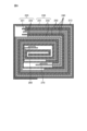
- FIG. 1 is a schematic cross-sectional view showing an example of a secondary battery according to the first embodiment.
- FIG. 2 is a schematic cross-sectional view showing an example of a secondary battery according to the second embodiment.
- FIG. 3 is a schematic cross-sectional view showing an example of a secondary battery according to the third embodiment.
- FIG. 4 is a schematic enlarged view of area A in FIG.
- FIG. 5 is a schematic cutaway diagram showing an example of the secondary battery according to the fourth embodiment.
- FIG. 6 is a schematic cross-sectional view taken along line VI-VI in FIG.
- FIG. 1 is a schematic cross-sectional view showing an example of a secondary battery according to the first embodiment.
- the secondary battery 1 in the first embodiment is an all-solid-state battery in which the electrolyte is solid, and is a lithium ion secondary battery.
- the secondary battery 1 includes a protective layer 10, a positive electrode 20, a negative electrode 30, a solid electrolyte layer 40, and an insulating layer 50.
- the secondary battery 1 has a structure in which a sheet-like positive electrode 20, a negative electrode 30, and a solid electrolyte layer 40 are stacked.
- the Z direction refers to the stacking direction of the positive electrode 20, the negative electrode 30, and the solid electrolyte layer 40
- the X direction refers to the direction perpendicular to the Z direction and parallel to the cross section of FIG.
- the Y direction refers to a direction perpendicular to the X direction and the Z direction.
- one of the X directions is sometimes described as the +X direction and the other as the ⁇ X direction.
- one of the Z directions may be described as +Z direction and the other as ⁇ Z direction.
- the protective layer 10 is a layer provided to physically and chemically protect the secondary battery 1.
- the protective layer 10 is provided so as to overlap the laminate of the positive electrode 20, the negative electrode 30, and the solid electrolyte layer 40 when viewed in plan in the Z direction, and in the example of FIG. 1, the positive electrode 20, the negative electrode 30, It is provided on both sides in the Z direction of the laminate with the solid electrolyte layer 40.
- the material of the protective layer 10 is not particularly limited as long as it is insulating, and examples thereof include resin, glass, and ceramics.
- the positive electrode 20 includes a positive electrode current collector layer 21 and a positive electrode active material layer 22.
- the positive electrode 20 has a structure in which the positive electrode active material layer 22 is laminated in the -Z direction of the positive electrode current collector layer 21, but this is just an example, and the positive electrode active material layer 22 is stacked in the +Z direction of the positive electrode current collector layer 21. They may be stacked in the same direction.
- the positive electrode current collector layer 21 is a layer that has conductivity.
- the end face of the positive electrode current collector layer 21 in the +X direction is exposed and can be connected to the outside. That is, the end face of the positive electrode current collector layer 21 in the +X direction serves as the positive electrode of the secondary battery 1.
- the material of the positive electrode current collector layer 21 is not particularly limited as long as it has conductivity, and examples thereof include metal materials such as silver, palladium, gold, platinum, aluminum, copper, and nickel, and carbon materials.
- the positive electrode active material layer 22 is a layer containing a positive electrode active material.
- the positive electrode active material layer 22 is laminated on the positive electrode current collector layer 21.
- the positive electrode active material is not particularly limited, and includes, for example, a lithium-containing phosphoric acid compound having a Nasicon-type structure, a lithium-containing phosphoric acid compound having an olivine-type structure, a lithium-containing layered oxide, and a lithium-containing oxide having a spinel-type structure. At least one type selected from the group consisting of:
- An example of a lithium-containing phosphoric acid compound having a Nasicon type structure includes Li 3 V 2 (PO 4 ) 3 and the like.
- lithium-containing phosphoric acid compounds having an olivine structure examples include Li 3 Fe 2 (PO 4 ) 3 and LiMnPO 4 .
- lithium-containing layered oxides include LiCoO 2 , LiCo 1/3 Ni 1/3 Mn 1/3 O 2 , and the like.
- lithium-containing oxides having a spinel structure examples include LiMn 2 O 4 , LiNi 0.5 Mn 1.5 O 4 , and the like.
- the material included in the positive electrode active material layer 22 is not limited to the positive electrode active material, and may also include a solid electrolyte and a sintering aid, which will be described later.
- the sintering aid is not particularly limited, and examples thereof include lithium oxide, sodium oxide, potassium oxide, boron oxide, silicon oxide, bismuth oxide, and phosphorus oxide.
- the negative electrode 30 includes a negative electrode current collector layer 31 , a peel prevention layer 32 , a negative electrode active material layer 33 , and a cap layer 34 .
- the negative electrode current collector layer 31 is a layer that has conductivity.
- the negative electrode current collector layer 31 is an example of a "negative electrode current collector.”
- the negative electrode current collector layer 31 has an exposed end face in the ⁇ X direction, and can be connected to the outside. That is, the end face of the negative electrode current collector layer 31 in the -X direction serves as the negative electrode of the secondary battery 1.
- the thickness of the negative electrode current collector layer 31 is not particularly limited, but is preferably thicker than the negative electrode active material layer 33 described later, and is approximately 30 ⁇ m.
- the material of the negative electrode current collector layer 31 is a conductive metal, and includes at least one metal selected from copper, nickel, and iron.
- the material of the negative electrode current collector layer 31 is not limited to this, and may further include a metal material such as palladium, gold, platinum, or aluminum. Further, the negative electrode current collector layer 31 is not limited to one layer, and may include a plurality of layers, such as stainless steel coated with nickel on the peel prevention layer 32 side, for example. In the following description, the material constituting the negative electrode current collector layer 31 may be referred to as a "negative electrode current collector material.”
- the anti-peeling layer 32 is a layer provided on the negative electrode current collector layer 31. Peeling prevention layer 32 is provided between negative electrode current collector layer 31 and negative electrode active material layer 33.
- the peel prevention layer 32 is an example of a "first layer”.
- the thickness of the peel prevention layer 32 is 5 nm or more and 55 nm or less. In the example of FIG. 1, the peel prevention layer 32 is provided in the +Z direction of the negative electrode current collector layer 31.
- the peel prevention layer 32 is made of silicon, negative electrode current collector material, titanium (Ti), nickel (Ni), zinc (Zn), silver (Ag), iron (Fe), boron (B), indium (In), and germanium. (Ge).
- the peel prevention layer 32 can suppress peeling between the negative electrode current collector layer 31 and the negative electrode active material layer 33 when the negative electrode active material layer 33 expands.
- the cycle characteristics of the secondary battery 1 can be improved.
- the element constituting the anti-peeling layer 32, excluding silicon and the negative electrode current collector material is preferably titanium. In this case, the resistance of the peel prevention layer 32 can be reduced.
- the elements constituting the anti-peeling layer 32, excluding silicon and the negative electrode current collector material may be referred to as the "first metal".
- the anti-peeling layer 32 contains silicon on the negative electrode active material layer 33 side. That is, silicon and the first metal are mixed on the side of the negative electrode active material layer 33 of the peel prevention layer 32.
- the concentration of silicon in the anti-peeling layer 32 is determined by XPS (X-ray Photoelectron Spectroscopy), AES (Auger Electron Spectroscopy), SIMS (Secondary Ion Mass). It can be measured by a composition analysis method in the depth direction such as spectrometry.
- the peel prevention layer 32 can suppress the interfacial energy with the negative electrode active material layer 33, and can further reduce the resistance between the negative electrode current collector layer 31 and the negative electrode active material layer 33.
- the peel prevention layer 32 does not contain silicon on the negative electrode current collector layer 31 side. That is, it can be said that the peel prevention layer 32 is a layer in which silicon is diffused only in the portion that contacts the negative electrode active material layer 33 in the thickness direction. Therefore, it can be said that the concentration of silicon contained in the peel prevention layer 32 on the negative electrode active material layer 33 side is higher than the silicon concentration contained in the peel prevention layer 32 on the negative electrode current collector layer 31 side.
- the peel prevention layer 32 includes a negative electrode current collector material on the negative electrode current collector layer 31 side. That is, on the side of the negative electrode current collector layer 31 of the peel prevention layer 32, the negative electrode current collector material and the first metal are mixed.
- the concentration of the negative electrode current collector material in the peel prevention layer 32 can be measured by a composition analysis method in the depth direction such as XPS, AES, SIMS, etc.
- the peel prevention layer 32 can suppress the interfacial energy with the negative electrode current collector layer 31, and can further reduce the resistance between the negative electrode current collector layer 31 and the negative electrode active material layer 33.
- the peel prevention layer 32 does not include a negative electrode current collector material on the negative electrode active material layer 33 side.
- the peel prevention layer 32 is a layer in which the negative electrode current collector material is diffused only in the portion that contacts the negative electrode current collector layer 31 in the thickness direction. Therefore, the concentration of the negative electrode current collector material contained in the negative electrode current collector layer 31 side of the peel prevention layer 32 is higher than the concentration of the negative electrode current collector material contained in the negative electrode active material layer 33 side of the peel prevention layer 32. It can be said that
- the negative electrode active material layer 33 is a layer containing a negative electrode active material.
- the negative electrode active material layer 33 is provided in the +Z direction of the peel prevention layer 32.
- the thickness of the negative electrode active material layer 33 is 2 ⁇ m or more and 5 ⁇ m or less. Thereby, the capacity of the secondary battery 1 can be improved.
- the negative electrode active material layer 33 contains silicon as a negative electrode active material.
- the crystallinity of silicon is not particularly limited, and may be amorphous, for example.
- the negative electrode active material is doped silicon.
- the dopant element for silicon in the negative electrode active material at least one element selected from boron, phosphorus (P), aluminum, bismuth (Bi), lithium (Li), and oxygen (O) can be used. Thereby, it is possible to suppress a decrease in the capacity of the secondary battery 1 due to the dopant.
- the cap layer 34 is a layer provided on the negative electrode active material layer 33.
- the cap layer 34 is an example of a "second layer".
- the cap layer 34 is provided in the +Z direction of the negative electrode active material layer 33.
- the thickness of the cap layer 34 is 5 nm or more and 55 nm or less.
- the cap layer 34 is made of silicon and at least one of titanium (Ti), nickel (Ni), zinc (Zn), silver (Ag), iron (Fe), boron (B), indium (In), and germanium (Ge). Contains more than one type. Thereby, the cap layer 34 has malleability. Therefore, even when the thickness of the negative electrode active material layer 33 is set to 2 ⁇ m or more, the stress generated by the expansion of the negative electrode active material layer 33 is applied to the cap layer 34, which has malleability and is difficult to crack. Therefore, generation of cracks in the negative electrode active material layer 33 can be suppressed. Therefore, damage to the negative electrode active material layer 33 can be suppressed, so that the cycle characteristics of the secondary battery 1 can be improved.
- the cap layer 34 is deformed so as to be pressed against the solid electrolyte layer 40, so that the cap layer 34 and the solid electrolyte layer 40 are in close contact with each other, and the cap layer 34 and the solid electrolyte layer 40 are in close contact with each other.
- the interfacial resistance with layer 40 can be reduced.
- the element constituting the cap layer 34 other than silicon is preferably titanium. Thereby, the resistance of the cap layer 34 can be reduced.
- the elements constituting the cap layer 34 excluding silicon are preferably the same as the elements constituting the peel prevention layer 32 excluding silicon and the negative electrode current collector material. Thereby, the stress of the negative electrode 30 can be uniformly relaxed.
- the elements constituting the cap layer 34 other than silicon may be referred to as "second metals.”
- the cap layer 34 contains silicon throughout its thickness. Thereby, the cap layer 34 can further reduce the interfacial resistance with the solid electrolyte layer 40. Further, it is preferable that the concentration of the second metal in the cap layer 34 decreases as it approaches the negative electrode active material layer 33. That is, it is preferable that the cap layer 34 has a silicon concentration gradient in the thickness direction, and the closer it is to the negative electrode active material layer 33, the higher the silicon concentration is.
- the silicon concentration of the cap layer 34 can be measured by a composition analysis in the depth direction using XPS, AES, SIMS, or the like.
- the stress in the cap layer 34 changes continuously in the Z direction, so it is possible to further suppress the generation of cracks due to the stress in the negative electrode active material layer 33. Further, since the concentration of the second metal changes continuously in the direction of the negative electrode active material layer 33, the interfacial energy between the cap layer 34 and the negative electrode active material layer 33 can be suppressed, and the interfacial energy between the cap layer 34 and the negative electrode active material layer The interfacial resistance with 33 can be reduced.
- the silicon concentration in the cap layer 34 is not limited to having a gradient in the thickness direction, and may be uniform.
- the configuration of the negative electrode 30 is not limited to the above.
- the negative electrode 30 has a structure in which a peel prevention layer 32, a negative electrode active material layer 33, and a cap layer 34 are laminated in the +Z direction of the negative electrode current collector layer 31. This is just an example, and the layers may be stacked in the -Z direction of the negative electrode current collector layer 31.
- Solid electrolyte layer 40 is a layer provided between positive electrode 20 and negative electrode 30.
- the solid electrolyte layer 40 is a sintered body containing a solid electrolyte.
- the material of the solid electrolyte is not particularly limited as long as it is a material that allows ions to move between the positive electrode 20 and the negative electrode 30.
- Examples of the solid electrolyte material include a lithium-containing phosphoric acid compound having a Nasicon structure, an oxide having a perovskite structure, and an oxide having a garnet type or garnet type similar structure.
- the lithium-containing phosphoric acid compound having a Nasicon structure is Li x My (PO 4 ) 3 (1 ⁇ x ⁇ 2, 1 ⁇ y ⁇ 2, M is at least one of Ti, Ge, Al, Ga, and Zr).
- An example of a lithium-containing phosphoric acid compound having a Nasicon structure includes, for example, Li 1.2 Al 0.2 Ti 1.8 (PO 4 ).
- Examples of oxides having a perovskite structure include La 0.55 Li 0.35 TiO 3 and the like.
- An example of an oxide having a garnet type or garnet type similar structure includes Li 7 La 3 Zr 2 O 12 and the like. Note that the material of the solid electrolyte layer 40 is not limited to the solid electrolyte, and may include the above-mentioned sintering aid.
- the side reinforcement portion 60 is provided to prevent short circuit of the secondary battery 1.
- the side reinforcement portions 60 are provided on the end faces of the positive electrode 20, the negative electrode 30, and the solid electrolyte layer 40 in the X direction and the Y direction.
- the material of the side reinforcement portion 60 is not particularly limited as long as it is an insulating material, and examples thereof include resin, glass, and ceramics.
- the negative electrode 30 has a negative electrode current collector (negative electrode current collector layer 31), a negative electrode active material layer 33, and a space between the negative electrode current collector and the negative electrode active material layer 33.
- the negative electrode current collector includes a first layer (peeling prevention layer 32) provided on the negative electrode active material layer 33 and a second layer (cap layer 34) provided on the negative electrode active material layer 33.
- the negative electrode active material layer 33 contains silicon, and the first layer contains silicon, the metal elements constituting the negative electrode current collector, titanium, nickel,
- the second layer contains silicon and at least one of titanium, nickel, zinc, silver, iron, boron, indium, and germanium. include.
- the second layer suppresses the generation of cracks in the negative electrode active material layer 33, and the negative electrode current collector and the negative electrode active material layer 33 are separated from each other. Since this can be suppressed by the first layer, the cycle maintenance rate can be improved.
- the elements constituting the first layer, excluding silicon and the metal constituting the negative electrode current collector are the same as the elements constituting the second layer, excluding silicon. Thereby, the stress of the negative electrode 30 can be uniformly relaxed.
- the element constituting the first layer excluding silicon and the metal constituting the negative electrode current collector is titanium
- the element constituting the second layer excluding silicon is titanium
- the concentration of silicon contained in the negative electrode active material layer side of the first layer is higher than the concentration of silicon contained in the negative electrode current collector side of the first layer, and The concentration of the negative electrode current collector material contained in the first layer is higher than the concentration of the negative electrode current collector material contained in the negative electrode active material layer 33 side of the first layer, and the second layer contains silicon throughout the thickness direction. . Thereby, the interfacial energy between the cap layer 34 and the negative electrode active material layer 33 can be further suppressed, and the interfacial resistance between the second layer and the negative electrode active material layer 33 can be further reduced.
- the interfacial energy with the negative electrode active material layer 33 can be further suppressed, and the negative electrode current collector The resistance between the negative electrode active material layer 33 and the negative electrode active material layer 33 can be further reduced.
- the concentration of the negative electrode current collector material in the first layer changes continuously in the direction in which the negative electrode current collector is provided, the interfacial energy with the negative electrode current collector can be further suppressed. The resistance between the electric body and the negative electrode active material layer 33 can be further reduced.
- the secondary battery 1 includes a positive electrode 20, a negative electrode 30, and an electrolyte (solid electrolyte layer 40). With this configuration, the cycle maintenance rate can be improved.
- the negative electrode 30 according to this embodiment is manufactured, for example, by the following method.
- a first metal layer, a silicon-containing layer, and a second metal layer are laminated on the negative electrode current collector layer 31 in this order.
- the lamination process is performed without contact with air, and is performed by, for example, sputtering, chemical vapor deposition, ion plating, or the like.
- the first metal layer is a layer made of a first metal, and has a thickness of 0.1 ⁇ m or more and 1 ⁇ m or less.
- the second metal layer is a layer made of a second metal, and has a thickness of 0.1 ⁇ m or more and 1 ⁇ m or less.
- a silicon-containing layer is a layer made of a silicon-containing material, for example a layer of a mixture of silicon and a dopant. In this case, silicon and the dopant are simultaneously deposited on the first metal layer and mixed.
- the laminate including the negative electrode current collector layer 31 is annealed.
- the silicon-containing layer becomes doped silicon
- the first metal of the first metal layer becomes the anti-peeling layer 32
- the second metal of the second metal layer diffuses into the silicon-containing layer to form the cap layer 34.
- Ru The annealing conditions are such that silicon is included throughout the thickness of the cap layer 34.
- a portion of the silicon-containing layer in which the first metal or the second metal has not diffused becomes the negative electrode active material layer 33.
- FIG. 2 is a schematic cross-sectional view showing an example of a secondary battery according to the second embodiment.
- the secondary battery according to this embodiment will be described below. Note that similar configurations are given the same reference numerals and explanations will be omitted.
- a secondary battery 1A according to the second embodiment is similar to the first embodiment and the second embodiment in that the negative electrode 30A includes a plurality of negative electrode active material layers 33a to 33d and a plurality of cap layers 34a to 34d. Different from secondary battery 1.
- the cap layers 34a to 34d are examples of "second layers". The thickness of each of the plurality of negative electrode active material layers 33a to 33d and the plurality of cap layers 34a to 34d is smaller than the thickness of the peel prevention layer 32.
- the negative electrode active material layers 33a to 33d and the cap layers 34a to 34d include the negative electrode active material layer 33d, the cap layer 34d, the negative electrode active material layer 33c, The cap layer 34c, the negative electrode active material layer 33b, the cap layer 34b, the negative electrode active material layer 33a, and the cap layer 34a are laminated in this order in the +Z direction of the peel prevention layer 32. That is, in the secondary battery 1A, it can be said that the cap layers 34a to 34d are alternately laminated with the negative electrode active material layers 33a to 33d in the Z direction.
- the cap layers 34b to 34d can suppress peeling of the negative electrode active material layers 33a to 33d, thereby improving the cycle characteristics of the secondary battery 1A.
- the second metal contained in the cap layers 34b to 34d acts as a surfactant (surfactant) for the silicon-containing layer in the production of the negative electrode 30A, so that the silicon-containing layer becomes thicker, so the secondary metal 1 can be improved. More specifically, in manufacturing the negative electrode 30A, the surface energy of the first silicon-containing layer is lowered by laminating the second metal layer on the silicon-containing layer, and the second silicon-containing layer laminated on the second metal layer reduces the surface energy of the first silicon-containing layer. Thickening of the layer is promoted.
- FIG. 3 is a schematic cross-sectional view showing an example of a secondary battery according to the third embodiment.
- the secondary battery 100 according to the third embodiment is a cylindrical battery and includes a liquid electrolyte.
- the secondary battery 200 includes a casing 110, a positive electrode 120, a negative electrode 130, and a separator 150.
- the casing 110 is a case that houses an electrode body and an electrolytic solution (not shown) therein.
- the casing 110 includes a battery can 111, a lid 112, a heat sensitive resistance element 113, a safety valve mechanism 114, a gasket 115, a positive lead 116, a negative lead 117, a center pin 119, an insulating plate 118, Equipped with.
- the battery can 111 is a cylindrical member that includes an end surface that becomes the negative electrode of the secondary battery 100. That is, the battery can 111 has a cylindrical shape with one end surface closed and the other end surface open.
- the battery can 111 is a conductor, and is made of, for example, an iron (Fe) base material whose surface is plated with nickel (Ni).
- the lid 112 is a disc-shaped member that includes a protrusion that becomes the positive electrode of the secondary battery 100.
- the lid body 112 is provided on the open end surface of the battery can 111.
- the lid 112 is made of metal, and is made of the same material as the battery can 111, for example.
- the direction in which the cylindrical portion of the battery can 111 extends is sometimes described as the longitudinal direction of the secondary battery 100.
- the positive electrode of the secondary battery 100 refers to the protrusion of the lid 112
- the negative electrode of the secondary battery 100 refers to the closed end surface of the battery can 111.
- the heat sensitive resistance element 113 is an element whose resistance increases as the temperature rises.
- the heat sensitive resistance element 113 is provided on the negative pole side with respect to the lid body 112.
- the heat-sensitive resistance element 113 increases its resistance value and limits the current when the secondary battery 100 becomes high temperature due to a short circuit or the like.
- the safety valve mechanism 114 is a mechanism whose shape changes depending on the gas pressure within the casing 110.
- the safety valve mechanism 114 is provided on the negative pole side with respect to the heat sensitive resistance element 113.
- the safety valve mechanism 114 is electrically connected to the lid 112 via the heat sensitive resistance element 113.
- the safety valve mechanism 114 has a projection on the negative electrode side, and when the gas pressure in the casing 110 is normal, it is in contact with the positive electrode lead 116 via the projection and is electrically connected.
- the safety valve mechanism 114 when the gas pressure inside the casing 110 increases, the protrusion reverses to the positive electrode side and separates from the positive electrode lead 116, thereby electrically disconnecting the positive electrode lead 116 and the lid 112.
- the gasket 115 is an annular member that fixes the lid 112, heat-sensitive resistance element 113, and safety valve mechanism 114 to the battery can 111.
- Gasket 115 is provided on the open end surface of battery can 111 .
- the gasket 115 brings the battery can 111 and the lid 112 into close contact with each other, making the inside of the casing 110 airtight.
- Gasket 115 is an insulator.
- the positive electrode lead 116 is a terminal connected to a positive electrode 120 of an electrode body described later.
- the positive electrode lead 116 is electrically connected to the lid 112 via the safety valve mechanism 114 and the heat sensitive resistance element 113.
- the positive electrode lead 116 is a conductor, and is made of aluminum (Al), for example.
- the negative electrode lead 117 is a terminal connected to a negative electrode 130 of an electrode body described later. Negative electrode lead 117 is electrically connected to battery can 111 .
- the negative electrode lead 117 is a conductor, and is made of nickel (Ni), for example.
- the insulating plate 118 is a plate-shaped member that is an insulator. Two insulating plates 118 are provided so as to cover a cross section of an electrode body, which will be described later, on the positive electrode side of the secondary battery 100 and a cross section on the negative electrode side of the secondary battery 100, respectively.
- the center pin 119 is provided at the central axis of the electrode body.
- the center pin 119 is a linear member having a length in the longitudinal direction of the secondary battery 100.
- the material of the center pin 119 is not particularly limited, and is, for example, metal.
- FIG. 4 is an enlarged view of area A in FIG. 3.
- a positive electrode 120 and a negative electrode 130 according to the third embodiment have a structure in which they are stacked with a separator 150 in between, and are provided inside a battery can 111.
- the positive electrode 120, the negative electrode 130, and the separator 150 are stacked in the radial direction of the secondary battery 100 with the center pin 119 as the center.
- the positive electrode 120 includes a positive electrode current collector layer 121 and a positive electrode active material layer 122.
- a positive electrode current collector layer 121 is stacked on two positive electrode active material layers 122.
- the material and thickness of the positive electrode current collector layer 121 are the same as those of the positive electrode current collector layer 21 in the first embodiment.
- the material and thickness of the positive electrode active material layer 122 are the same as those of the positive electrode active material layer 22 in the first embodiment.
- the negative electrode 130 includes a negative electrode current collector layer 131 and a negative electrode material layer 132.
- the negative electrode current collector layer 131 is an example of a "negative electrode current collector.”
- a negative electrode current collector layer 131 is laminated on two negative electrode material layers 132.
- the negative electrode current collector layer 131 is made of the same material as the negative electrode current collector layer 31 in the first embodiment.
- the negative electrode material layer 132 is a layer containing a negative electrode active material layer.
- the negative electrode material layer 132 includes a peel prevention layer, a negative electrode active material layer, and a cap layer, which are made of the same materials as in the first embodiment.
- the anti-peeling layer is an example of a "first layer” and the cap layer is an example of a "second layer.”
- the cap layer is a thinner layer than the anti-peeling layer.
- the negative electrode material layer 132 is a laminate in which a peel prevention layer, a negative electrode active material layer, and a cap layer are laminated in this order from the negative electrode current collector layer 131 side. Thereby, even if the negative electrode active material layer expands, since the peeling prevention layer is provided, peeling of the negative electrode material layer 132 from the negative electrode current collector layer 131 can be suppressed.
- the cycle characteristics of the secondary battery 100 can be improved.
- the separator 150 is a layer that insulates the positive electrode 120 and the negative electrode 130.
- the separator 150 is provided so that the positive electrode 120 and the negative electrode 130 do not come into direct contact with each other, and is laminated between the positive electrode 120 and the negative electrode 130 in the electrode body.
- the material of the separator 150 is preferably electrically stable, chemically stable with respect to the positive electrode active material, negative electrode active material, and electrolyte, and insulating.
- a layer made of a polymeric nonwoven fabric, a porous film, glass, or ceramic fibers can be used. More preferably, the material of separator 150 includes a porous polyolefin film.
- the separator 150 may be composed of a plurality of layers, and may be a composite of a porous polyolefin film and a heat-resistant membrane containing polyimide, glass, or ceramic fibers.
- the space surrounded by the insulating plate 118 and the battery can 111 is filled with electrolyte.
- the electrolyte includes an electrolyte salt and a solvent that dissolves the electrolyte salt.
- the electrolyte salt include lithium perchlorate (LiClO 4 ), lithium hexafluorophosphate (LiPF 6 ), lithium tetrafluoroborate (LiBF 4 ), and lithium bis(trifluoromethanesulfonyl)imide (LiN(SO 2 ).
- lithium bis(pentafluoroethanesulfonyl)imide LiN(SO 2 C 2 F 5 ) 2
- lithium hexafluoroarsenate LiAsF 6
- the solvent include lactone solvents such as ⁇ -butyrolactone, ⁇ -valerolactone, ⁇ -valerolactone, or ⁇ -caprolactone, ethylene carbonate, propylene carbonate, butylene carbonate, vinylene carbonate, dimethyl carbonate, ethylmethyl carbonate, or diethyl carbonate.
- carbonate ester solvents such as 1,2-dimethoxyethane, 1-ethoxy-2-methoxyethane, 1,2-diethoxyethane, tetrahydrofuran or 2-methyltetrahydrofuran, nitrile solvents such as acetonitrile, sulfolane
- ether solvents such as 1,2-dimethoxyethane, 1-ethoxy-2-methoxyethane, 1,2-diethoxyethane, tetrahydrofuran or 2-methyltetrahydrofuran
- nitrile solvents such as acetonitrile
- sulfolane non-aqueous solvents containing system solvents, phosphoric acids, phosphate ester solvents, pyrrolidones, and the like.
- FIG. 5 is a cutaway diagram showing an example of a secondary battery according to the fourth embodiment.
- FIG. 6 is a schematic cross-sectional view taken along line VI-VI in FIG.
- the secondary battery 200 according to the fourth embodiment includes a gel electrolyte.
- the secondary battery 200 according to the fourth embodiment includes a battery element, an exterior member 211, an adhesive material 212, a protective material 213, a positive electrode 220, a negative electrode 230, and a gel. It includes a shaped electrolyte layer 240, a separator 250, a positive electrode lead 260, and a negative electrode lead 270.
- the exterior member 211 is a case of the secondary battery 200.
- Exterior member 211 includes an insulating layer, a metal layer, and an outermost layer.
- the exterior member 211 has a structure in which an insulating layer, a metal layer, and an outermost layer are laminated in this order from the inside, and then bonded together by laminating or the like.
- the insulating layer of the exterior member 211 is made of, for example, resin such as polyethylene, polypropylene, modified polyethylene, modified polypropylene, or polyolefin resin containing ethylene or propylene as a monomer. Thereby, the exterior member 211 can lower moisture permeability of the secondary battery 200 and improve airtightness.
- the metal layer of the exterior member 211 is a plate or foil film made of metal such as aluminum, stainless steel, nickel, or iron.
- the outermost layer may be made of any material, but is preferably made of a material that has high strength against tearing, piercing, etc., such as the same resin as the insulating layer or nylon.
- the adhesive material 212 is a member for making the exterior member 211 airtight.
- Adhesive material 212 is provided between exterior member 211 and positive electrode lead 260 and negative electrode lead 270.
- the material of the adhesive material 212 preferably has adhesiveness to the positive electrode lead 260 and the negative electrode lead 270.
- the adhesive material 212 is made of polyolefin resin such as polyethylene, polypropylene, modified polyethylene, or modified polypropylene.
- the positive electrode 220 includes a positive electrode current collector layer 221 and a positive electrode active material layer 222.
- the material and thickness of the positive electrode current collector layer 221 are the same as those of the positive electrode current collector layer 21 in the first embodiment. Further, the material and thickness of the positive electrode active material layer 222 are the same as those of the positive electrode active material layer 22 in the first embodiment.
- the negative electrode 230 includes a negative electrode current collector layer 231 and a negative electrode material layer 232.
- the negative electrode current collector layer 131 is an example of a "negative electrode current collector.”
- the negative electrode current collector layer 131 includes a peel prevention layer, a negative electrode active material layer, and a cap layer, which are made of the same materials as in the first embodiment. That is, the anti-peeling layer is an example of a "first layer” and the cap layer is an example of a "second layer.” Here, the cap layer is a thinner layer than the anti-peeling layer.
- the negative electrode material layer 232 is a laminate in which a peel prevention layer, a negative electrode active material layer, and a cap layer are laminated in this order from the negative electrode current collector layer 231 side. ing.
- the peeling prevention layer is provided, peeling of the negative electrode material layer 132 from the negative electrode current collector layer 131 can be suppressed.
- the cap layer is provided, deterioration of the negative electrode active material due to electrolyte gel entering the cracks can be suppressed. Therefore, the cycle characteristics of the secondary battery 200 can be improved.
- the positive electrode 220, the negative electrode 230, the gel electrolyte layer 240, and the separator 250 have a structure in which they are wound around a positive electrode lead 260 and a negative electrode lead 270. From the outside, that is, from the protective material 213 side: negative electrode current collector layer 231, negative electrode material layer 232, gel electrolyte layer 240, separator 250, gel electrolyte layer 240, positive electrode active material layer 222, positive electrode current collector layer 221, positive electrode The active material layer 222, the gel electrolyte layer 240, the separator 250, the gel electrolyte layer 240, and the negative electrode material layer 232 are laminated in this order.
- the gel electrolyte layer 240 is a layer that becomes the electrolyte of the secondary battery 200.
- the gel electrolyte layer 240 is a gel layer made of a polymer compound that retains an electrolyte.
- any polymer compound can be used as long as it absorbs a solvent and becomes a gel.
- polyvinylidene fluoride or vinylidene fluoride, and hexane Fluorine-based polymer compounds such as copolymers with fluoropropylene, ether-based polymer compounds such as polyethylene oxide or crosslinked products containing polyethylene oxide, or polymer compounds containing polyacrylonitrile, polypropylene oxide, or polymethyl methacrylate as monomers, etc.
- the polymer compound used as the gel of the gel electrolyte layer 240 is preferably a fluorine-based polymer compound, and more preferably a copolymer containing vinylidene fluoride and hexafluoropropylene as monomers. By using this material, stability against redox reactions can be improved.
- the copolymers of high molecular compounds used as the gel of the gel electrolyte layer 240 include monoesters of unsaturated dibasic acids such as monomethyl maleate, halogenated ethylenes such as trifluorochloroethylene, and vinylene carbonate. It may further contain as a monomer a cyclic carbonate ester of an unsaturated compound such as or an epoxy group-containing acryl vinyl monomer. In this case, cycle characteristics can be improved.
- the positive electrode lead 260 is a terminal drawn out from the positive electrode current collector layer 221 to the outside of the exterior member 211. That is, the positive electrode lead 260 is a terminal that becomes the positive electrode of the secondary battery 200. In FIG. 6, the positive electrode lead 260 is provided near the center of the portion surrounded by the protective material 213. The material of the positive electrode lead 260 is the same as that of the positive electrode lead 116 in the third embodiment.
- the negative electrode lead 270 is a terminal drawn out from the negative electrode current collector layer 231 to the outside of the exterior member 211. That is, the negative electrode lead 270 is a terminal that becomes the negative electrode of the secondary battery 200. In FIG. 6, the negative electrode lead 270 is provided near the center of the portion surrounded by the protective material 213. The material of the negative electrode lead 270 is the same as that of the positive electrode lead 116 in the third embodiment.
- the protective material 213 is a member that protects the secondary battery 200.
- the protective material 213 is provided so as to wrap around the negative electrode 230.
- the protective material 213 is, for example, an insulating tape.
Abstract
The present invention provides: a negative electrode which is capable of improving the cycle characteristics; and a secondary battery. A negative electrode according to the present invention is provided with: a negative electrode collector; a negative electrode active material layer; a first layer that is arranged between the negative electrode collector and the negative electrode active material layer; and a second layer that is arranged on the negative electrode active material layer. The negative electrode collector contains at least one element that is selected from among copper, nickel and iron; the negative electrode active material layer contains silicon; the first layer contains silicon, the metal element that constitutes the negative electrode collector, and at least one element that is selected from among titanium, nickel, zinc, silver, iron, boron, indium and germanium; and the second layer contains silicon and at least one element that is selected from among titanium, nickel, zinc, silver, iron, boron, indium and germanium.
Description
本開示は、負極及び二次電池に関する。
The present disclosure relates to a negative electrode and a secondary battery.
特許文献1に示すように、リチウムイオン二次電池の負極活物質として、ケイ素を主成分として用いる場合がある。
As shown in Patent Document 1, silicon is sometimes used as a main component as a negative electrode active material of a lithium ion secondary battery.
リチウムイオン二次電池の負極活物質として、ケイ素を主成分として用いた場合、初回の充放電時にケイ素がリチウムイオンを吸収することにより膨張することが知られている。そのため、負極活物質層に亀裂が生じ、また負極活物質層と負極集電体とが剥離することにより、サイクル特性が低下するおそれがあった。
It is known that when silicon is used as the main component as the negative electrode active material of a lithium ion secondary battery, silicon absorbs lithium ions and expands during the first charging and discharging. Therefore, there was a risk that cycle characteristics would deteriorate due to cracks occurring in the negative electrode active material layer and peeling between the negative electrode active material layer and the negative electrode current collector.
本開示は、上記に鑑みてなされたものであり、サイクル特性を向上できる負極及び二次電池を提供することを目的とする。
The present disclosure has been made in view of the above, and aims to provide a negative electrode and a secondary battery that can improve cycle characteristics.
一態様に係る負極は、負極集電体と、負極活物質層と、前記負極集電体と前記負極活物質層との間に設けられた第1の層と、前記負極活物質層に設けられた第2の層と、を備え、前記負極集電体は、銅、ニッケル、鉄のうち少なくとも1種類以上を含み、前記負極活物質層は、ケイ素を含み、前記第1の層は、ケイ素、前記負極集電体を構成する金属元素並びにチタン、ニッケル、亜鉛、銀、鉄、ホウ素、インジウム及びゲルマニウムのうち少なくとも1種類以上を含み、前記第2の層は、ケイ素並びにチタン、ニッケル、亜鉛、銀、鉄、ホウ素、インジウム及びゲルマニウムのうち少なくとも1種類以上を含む。
The negative electrode according to one embodiment includes a negative electrode current collector, a negative electrode active material layer, a first layer provided between the negative electrode current collector and the negative electrode active material layer, and a first layer provided in the negative electrode active material layer. the negative electrode current collector contains at least one of copper, nickel, and iron, the negative electrode active material layer contains silicon, and the first layer contains The second layer contains silicon, a metal element constituting the negative electrode current collector, and at least one of titanium, nickel, zinc, silver, iron, boron, indium, and germanium, and the second layer contains silicon, titanium, nickel, Contains at least one of zinc, silver, iron, boron, indium, and germanium.
一態様に係る二次電池は、前記負極と、正極と、電解質とを備える。
A secondary battery according to one embodiment includes the negative electrode, a positive electrode, and an electrolyte.
本発明によれば、サイクル特性を向上できる。
According to the present invention, cycle characteristics can be improved.
以下に、本開示の実施の形態を説明する。なお、この実施の形態により本開示が限定されるものではない。
Embodiments of the present disclosure will be described below. Note that the present disclosure is not limited to this embodiment.
(第1実施形態)
図1は、第1実施形態に係る二次電池の一例を示す模式的な断面図である。第1実施形態における二次電池1は、電解質が固体である全固体電池であり、リチウムイオン二次電池である。図1に示すように、二次電池1は、保護層10と、正極20と、負極30と、固体電解質層40と、絶縁層50とを備える。図1の例では、二次電池1は、シート状の正極20と、負極30と、固体電解質層40とが積層した構造となっている。 (First embodiment)
FIG. 1 is a schematic cross-sectional view showing an example of a secondary battery according to the first embodiment. Thesecondary battery 1 in the first embodiment is an all-solid-state battery in which the electrolyte is solid, and is a lithium ion secondary battery. As shown in FIG. 1, the secondary battery 1 includes a protective layer 10, a positive electrode 20, a negative electrode 30, a solid electrolyte layer 40, and an insulating layer 50. In the example of FIG. 1, the secondary battery 1 has a structure in which a sheet-like positive electrode 20, a negative electrode 30, and a solid electrolyte layer 40 are stacked.
図1は、第1実施形態に係る二次電池の一例を示す模式的な断面図である。第1実施形態における二次電池1は、電解質が固体である全固体電池であり、リチウムイオン二次電池である。図1に示すように、二次電池1は、保護層10と、正極20と、負極30と、固体電解質層40と、絶縁層50とを備える。図1の例では、二次電池1は、シート状の正極20と、負極30と、固体電解質層40とが積層した構造となっている。 (First embodiment)
FIG. 1 is a schematic cross-sectional view showing an example of a secondary battery according to the first embodiment. The
本実施形態を示す図面において、Z方向は、正極20、負極30及び固体電解質層40の積層方向を指し、X方向は、Z方向に直交し、かつ図1の断面に平行な方向を指し、Y方向は、X方向及びZ方向に直交する方向を指す。また、本実施形態の説明において、X方向のうち一方を+X方向、他方を-X方向として説明することがある。同様に、Z方向のうち、一方を+Z方向、他方を-Z方向として説明することがある。
In the drawings showing this embodiment, the Z direction refers to the stacking direction of the positive electrode 20, the negative electrode 30, and the solid electrolyte layer 40, and the X direction refers to the direction perpendicular to the Z direction and parallel to the cross section of FIG. The Y direction refers to a direction perpendicular to the X direction and the Z direction. Furthermore, in the description of this embodiment, one of the X directions is sometimes described as the +X direction and the other as the −X direction. Similarly, one of the Z directions may be described as +Z direction and the other as −Z direction.
保護層10は、二次電池1を物理的及び化学的に保護するために設けられる層である。保護層10は、Z方向に平面視して、正極20と、負極30と、固体電解質層40との積層体と重なるように設けられ、図1の例では、正極20と、負極30と、固体電解質層40との積層体のZ方向についての両側に設けられる。保護層10の材料は、絶縁性であれば特に限られず、例えば、樹脂、ガラス、セラミックスなどである。
The protective layer 10 is a layer provided to physically and chemically protect the secondary battery 1. The protective layer 10 is provided so as to overlap the laminate of the positive electrode 20, the negative electrode 30, and the solid electrolyte layer 40 when viewed in plan in the Z direction, and in the example of FIG. 1, the positive electrode 20, the negative electrode 30, It is provided on both sides in the Z direction of the laminate with the solid electrolyte layer 40. The material of the protective layer 10 is not particularly limited as long as it is insulating, and examples thereof include resin, glass, and ceramics.
正極20は、正極集電体層21と正極活物質層22とを備える。図1の例では、正極20は、正極集電体層21の-Z方向に正極活物質層22が積層された構造となっているが、あくまで一例であり、正極集電体層21の+Z方向に積層されてもよい。
The positive electrode 20 includes a positive electrode current collector layer 21 and a positive electrode active material layer 22. In the example of FIG. 1, the positive electrode 20 has a structure in which the positive electrode active material layer 22 is laminated in the -Z direction of the positive electrode current collector layer 21, but this is just an example, and the positive electrode active material layer 22 is stacked in the +Z direction of the positive electrode current collector layer 21. They may be stacked in the same direction.
正極集電体層21は、導電性を有する層である。図1の例では、正極集電体層21は、+X方向の端面が露出しており、外部と接続可能となっている。すなわち、正極集電体層21の+X方向の端面は、二次電池1のプラス極となっている。正極集電体層21の材料は、導電性を有するものであれば、特に限定されず、銀、パラジウム、金、プラチナ、アルミニウム、銅、ニッケル等の金属材料及び炭素材料が挙げられる。
The positive electrode current collector layer 21 is a layer that has conductivity. In the example of FIG. 1, the end face of the positive electrode current collector layer 21 in the +X direction is exposed and can be connected to the outside. That is, the end face of the positive electrode current collector layer 21 in the +X direction serves as the positive electrode of the secondary battery 1. The material of the positive electrode current collector layer 21 is not particularly limited as long as it has conductivity, and examples thereof include metal materials such as silver, palladium, gold, platinum, aluminum, copper, and nickel, and carbon materials.
正極活物質層22は、正極活物質を含む層である。正極活物質層22は、正極集電体層21に積層される。正極活物質は、特に限定されず、例えば、ナシコン型構造を有するリチウム含有リン酸化合物、オリビン型構造を有するリチウム含有リン酸化合物、リチウム含有層状酸化物、及びスピネル型構造を有するリチウム含有酸化物等からなる群から選択される少なくとも一種が挙げられる。ナシコン型構造を有するリチウム含有リン酸化合物の一例としては、Li3V2(PO4)3等が挙げられる。オリビン型構造を有するリチウム含有リン酸化合物の一例としては、Li3Fe2(PO4)3、LiMnPO4等が挙げられる。リチウム含有層状酸化物の一例としては、LiCoO2、LiCo1/3Ni1/3Mn1/3O2等が挙げられる。スピネル型構造を有するリチウム含有酸化物の一例としては、LiMn2O4、LiNi0.5Mn1.5O4等が挙げられる。
The positive electrode active material layer 22 is a layer containing a positive electrode active material. The positive electrode active material layer 22 is laminated on the positive electrode current collector layer 21. The positive electrode active material is not particularly limited, and includes, for example, a lithium-containing phosphoric acid compound having a Nasicon-type structure, a lithium-containing phosphoric acid compound having an olivine-type structure, a lithium-containing layered oxide, and a lithium-containing oxide having a spinel-type structure. At least one type selected from the group consisting of: An example of a lithium-containing phosphoric acid compound having a Nasicon type structure includes Li 3 V 2 (PO 4 ) 3 and the like. Examples of lithium-containing phosphoric acid compounds having an olivine structure include Li 3 Fe 2 (PO 4 ) 3 and LiMnPO 4 . Examples of lithium-containing layered oxides include LiCoO 2 , LiCo 1/3 Ni 1/3 Mn 1/3 O 2 , and the like. Examples of lithium-containing oxides having a spinel structure include LiMn 2 O 4 , LiNi 0.5 Mn 1.5 O 4 , and the like.
なお、正極活物質層22が含む材料は、正極活物質に限られず、後述する固体電解質や焼結助剤を含んでいてもよい。焼結助剤は、特に限定されず、例えば、リチウム酸化物、ナトリウム酸化物、カリウム酸化物、酸化ホウ素、酸化ケイ素、酸化ビスマス及び酸化リンが挙げられる。
Note that the material included in the positive electrode active material layer 22 is not limited to the positive electrode active material, and may also include a solid electrolyte and a sintering aid, which will be described later. The sintering aid is not particularly limited, and examples thereof include lithium oxide, sodium oxide, potassium oxide, boron oxide, silicon oxide, bismuth oxide, and phosphorus oxide.
負極30は、負極集電体層31と、剥離防止層32と、負極活物質層33と、キャップ層34とを備える。
The negative electrode 30 includes a negative electrode current collector layer 31 , a peel prevention layer 32 , a negative electrode active material layer 33 , and a cap layer 34 .
負極集電体層31は、導電性を有する層である。ここで、負極集電体層31は、「負極集電体」の一例である。図1の例では、負極集電体層31は、-X方向の端面が露出しており、外部と接続可能となっている。すなわち、負極集電体層31の-X方向の端面は、二次電池1のマイナス極となっている。図1の例では、負極集電体層31の厚みは、特に限定されないが、後述する負極活物質層33より厚いことが好ましく、おおよそ30μmである。負極集電体層31の材料は、導電性を有する金属であり、銅、ニッケル、鉄のうち、少なくとも1種類以上の金属を含む。なお、負極集電体層31の材料は、これに限られず、例えば、パラジウム、金、プラチナ、アルミニウム等の金属材料を更に含んでいてもよい。また、負極集電体層31は、1つの層からなることに限られず、例えば、剥離防止層32側がニッケルで被膜されたステンレス鋼など、複数の層を備えるものであってもよい。以下の説明においては、負極集電体層31を構成する材料を「負極集電体材料」として説明することがある。
The negative electrode current collector layer 31 is a layer that has conductivity. Here, the negative electrode current collector layer 31 is an example of a "negative electrode current collector." In the example shown in FIG. 1, the negative electrode current collector layer 31 has an exposed end face in the −X direction, and can be connected to the outside. That is, the end face of the negative electrode current collector layer 31 in the -X direction serves as the negative electrode of the secondary battery 1. In the example of FIG. 1, the thickness of the negative electrode current collector layer 31 is not particularly limited, but is preferably thicker than the negative electrode active material layer 33 described later, and is approximately 30 μm. The material of the negative electrode current collector layer 31 is a conductive metal, and includes at least one metal selected from copper, nickel, and iron. Note that the material of the negative electrode current collector layer 31 is not limited to this, and may further include a metal material such as palladium, gold, platinum, or aluminum. Further, the negative electrode current collector layer 31 is not limited to one layer, and may include a plurality of layers, such as stainless steel coated with nickel on the peel prevention layer 32 side, for example. In the following description, the material constituting the negative electrode current collector layer 31 may be referred to as a "negative electrode current collector material."
剥離防止層32は、負極集電体層31に設けられる層である。剥離防止層32は、負極集電体層31と負極活物質層33との間に設けられる。ここで、剥離防止層32は、「第1の層」の一例である。剥離防止層32の厚さは5nm以上55nm以下の厚みとなっている。図1の例では、剥離防止層32は、負極集電体層31の+Z方向に設けられる。
The anti-peeling layer 32 is a layer provided on the negative electrode current collector layer 31. Peeling prevention layer 32 is provided between negative electrode current collector layer 31 and negative electrode active material layer 33. Here, the peel prevention layer 32 is an example of a "first layer". The thickness of the peel prevention layer 32 is 5 nm or more and 55 nm or less. In the example of FIG. 1, the peel prevention layer 32 is provided in the +Z direction of the negative electrode current collector layer 31.
剥離防止層32は、ケイ素、負極集電体材料並びにチタン(Ti)、ニッケル(Ni)、亜鉛(Zn)、銀(Ag)、鉄(Fe)、ホウ素(B)、インジウム(In)及びゲルマニウム(Ge)のうち少なくとも1種類以上を含む。これにより、剥離防止層32は、負極活物質層33が膨張した際に、負極集電体層31と負極活物質層33との剥離を抑制できる。これにより、二次電池1のサイクル特性を向上させることができる。ここで、ケイ素および負極集電体材料を除く、剥離防止層32を構成する元素は、チタンであることが好ましい。この場合、剥離防止層32の抵抗を低減できる。以下の説明においては、ケイ素および負極集電体材料を除く、剥離防止層32を構成する元素を「第1金属」として説明することがある。
The peel prevention layer 32 is made of silicon, negative electrode current collector material, titanium (Ti), nickel (Ni), zinc (Zn), silver (Ag), iron (Fe), boron (B), indium (In), and germanium. (Ge). Thereby, the peel prevention layer 32 can suppress peeling between the negative electrode current collector layer 31 and the negative electrode active material layer 33 when the negative electrode active material layer 33 expands. Thereby, the cycle characteristics of the secondary battery 1 can be improved. Here, the element constituting the anti-peeling layer 32, excluding silicon and the negative electrode current collector material, is preferably titanium. In this case, the resistance of the peel prevention layer 32 can be reduced. In the following description, the elements constituting the anti-peeling layer 32, excluding silicon and the negative electrode current collector material, may be referred to as the "first metal".
剥離防止層32は、負極活物質層33側にケイ素を含む。すなわち、剥離防止層32の負極活物質層33側は、ケイ素と第1金属とが混在している。ここで、剥離防止層32のケイ素の濃度はXPS(X-ray Photoelectron Spectroscopy)、AES(Auger Electron Spectroscopy)、SIMS(Secondary Ion Mass Spectrometry)などの深さ方向に対する組成分析法で測定できる。これにより、剥離防止層32は、負極活物質層33との界面エネルギーを抑制でき、負極集電体層31と負極活物質層33との間の抵抗をより低減できる。また、剥離防止層32は、負極集電体層31側にはケイ素は含んでいない。すなわち、剥離防止層32は、厚さ方向について負極活物質層33と接する部分のみにケイ素が拡散された層であるといえる。したがって、剥離防止層32の負極活物質層33側に含まれるケイ素の濃度は、剥離防止層32の負極集電体層31側に含まれるケイ素の濃度より高くなっているといえる。
The anti-peeling layer 32 contains silicon on the negative electrode active material layer 33 side. That is, silicon and the first metal are mixed on the side of the negative electrode active material layer 33 of the peel prevention layer 32. Here, the concentration of silicon in the anti-peeling layer 32 is determined by XPS (X-ray Photoelectron Spectroscopy), AES (Auger Electron Spectroscopy), SIMS (Secondary Ion Mass). It can be measured by a composition analysis method in the depth direction such as spectrometry. Thereby, the peel prevention layer 32 can suppress the interfacial energy with the negative electrode active material layer 33, and can further reduce the resistance between the negative electrode current collector layer 31 and the negative electrode active material layer 33. Further, the peel prevention layer 32 does not contain silicon on the negative electrode current collector layer 31 side. That is, it can be said that the peel prevention layer 32 is a layer in which silicon is diffused only in the portion that contacts the negative electrode active material layer 33 in the thickness direction. Therefore, it can be said that the concentration of silicon contained in the peel prevention layer 32 on the negative electrode active material layer 33 side is higher than the silicon concentration contained in the peel prevention layer 32 on the negative electrode current collector layer 31 side.
剥離防止層32は、負極集電体層31側に負極集電体材料を含む。すなわち、剥離防止層32の負極集電体層31側は、負極集電体材料と第1金属とが混在している。ここで、剥離防止層32の負極集電体材料の濃度はXPS、AES、SIMSなどの深さ方向に対する組成分析法で測定できる。これにより、剥離防止層32は、負極集電体層31との界面エネルギーを抑制でき、負極集電体層31と負極活物質層33との間の抵抗をより低減できる。また、剥離防止層32は、負極活物質層33側には負極集電体材料は含んでいない。すなわち、剥離防止層32は、厚さ方向について負極集電体層31と接する部分のみに負極集電体材料が拡散された層であるといえる。したがって、剥離防止層32の負極集電体層31側に含まれる負極集電体材料の濃度は、剥離防止層32の負極活物質層33側に含まれる負極集電体材料の濃度より高くなっているといえる。
The peel prevention layer 32 includes a negative electrode current collector material on the negative electrode current collector layer 31 side. That is, on the side of the negative electrode current collector layer 31 of the peel prevention layer 32, the negative electrode current collector material and the first metal are mixed. Here, the concentration of the negative electrode current collector material in the peel prevention layer 32 can be measured by a composition analysis method in the depth direction such as XPS, AES, SIMS, etc. Thereby, the peel prevention layer 32 can suppress the interfacial energy with the negative electrode current collector layer 31, and can further reduce the resistance between the negative electrode current collector layer 31 and the negative electrode active material layer 33. Furthermore, the peel prevention layer 32 does not include a negative electrode current collector material on the negative electrode active material layer 33 side. That is, it can be said that the peel prevention layer 32 is a layer in which the negative electrode current collector material is diffused only in the portion that contacts the negative electrode current collector layer 31 in the thickness direction. Therefore, the concentration of the negative electrode current collector material contained in the negative electrode current collector layer 31 side of the peel prevention layer 32 is higher than the concentration of the negative electrode current collector material contained in the negative electrode active material layer 33 side of the peel prevention layer 32. It can be said that
負極活物質層33は、負極活物質を含む層である。図1の例では、負極活物質層33は、剥離防止層32の+Z方向に設けられる。負極活物質層33の厚みは、2μm以上5μm以下である。これにより、二次電池1の容量を向上させることができる。
The negative electrode active material layer 33 is a layer containing a negative electrode active material. In the example of FIG. 1, the negative electrode active material layer 33 is provided in the +Z direction of the peel prevention layer 32. The thickness of the negative electrode active material layer 33 is 2 μm or more and 5 μm or less. Thereby, the capacity of the secondary battery 1 can be improved.
負極活物質層33は、負極活物質としてケイ素を含む。ケイ素の結晶性は特に限定されず、例えば、アモルファスであってよい。負極活物質は、ドープドシリコンであることが好ましい。負極活物質のケイ素のドーパント元素は、ホウ素、リン(P)、アルミニウム、ビスマス(Bi)、リチウム(Li)及び酸素(O)のうち少なくとも1種類以上の元素を用いることができる。これにより、ドーパントによる二次電池1の低容量化を抑制できる。
The negative electrode active material layer 33 contains silicon as a negative electrode active material. The crystallinity of silicon is not particularly limited, and may be amorphous, for example. Preferably, the negative electrode active material is doped silicon. As the dopant element for silicon in the negative electrode active material, at least one element selected from boron, phosphorus (P), aluminum, bismuth (Bi), lithium (Li), and oxygen (O) can be used. Thereby, it is possible to suppress a decrease in the capacity of the secondary battery 1 due to the dopant.
キャップ層34は、負極活物質層33に設けられる層である。ここで、キャップ層34は、「第2の層」の一例である。図1の例では、キャップ層34は、負極活物質層33の+Z方向に設けられる。キャップ層34の厚さは5nm以上55nm以下の厚みとなっている。
The cap layer 34 is a layer provided on the negative electrode active material layer 33. Here, the cap layer 34 is an example of a "second layer". In the example of FIG. 1, the cap layer 34 is provided in the +Z direction of the negative electrode active material layer 33. The thickness of the cap layer 34 is 5 nm or more and 55 nm or less.
キャップ層34は、ケイ素並びにチタン(Ti)、ニッケル(Ni)、亜鉛(Zn)、銀(Ag)、鉄(Fe)、ホウ素(B)、インジウム(In)及びゲルマニウム(Ge)のうち少なくとも1種類以上を含む。これにより、キャップ層34は、展性を有する。そのため、負極活物質層33の厚みを2μm以上とした場合であっても、負極活物質層33の膨張により発生する応力が、展性を有するために亀裂が発生しにくいキャップ層34に印加されるため、負極活物質層33に亀裂が発生することを抑制できる。したがって、負極活物質層33が破損することを抑制できるので、二次電池1のサイクル特性を向上できる。また、負極活物質層33が膨張した際に、キャップ層34が固体電解質層40に押し付けられるように変形することで、キャップ層34と固体電解質層40とが密着し、キャップ層34と固体電解質層40との界面抵抗を低減できる。ここで、ケイ素を除くキャップ層34を構成する元素は、チタンであることが好ましい。これにより、キャップ層34の抵抗を低減できる。また、ケイ素を除くキャップ層34を構成する元素は、ケイ素および負極集電体材料を除く、剥離防止層32を構成する元素と、同じであることが好ましい。これにより、負極30の応力を均質に緩和することができる。以下の説明においては、ケイ素を除くキャップ層34を構成する元素を「第2金属」として説明することがある。
The cap layer 34 is made of silicon and at least one of titanium (Ti), nickel (Ni), zinc (Zn), silver (Ag), iron (Fe), boron (B), indium (In), and germanium (Ge). Contains more than one type. Thereby, the cap layer 34 has malleability. Therefore, even when the thickness of the negative electrode active material layer 33 is set to 2 μm or more, the stress generated by the expansion of the negative electrode active material layer 33 is applied to the cap layer 34, which has malleability and is difficult to crack. Therefore, generation of cracks in the negative electrode active material layer 33 can be suppressed. Therefore, damage to the negative electrode active material layer 33 can be suppressed, so that the cycle characteristics of the secondary battery 1 can be improved. Further, when the negative electrode active material layer 33 expands, the cap layer 34 is deformed so as to be pressed against the solid electrolyte layer 40, so that the cap layer 34 and the solid electrolyte layer 40 are in close contact with each other, and the cap layer 34 and the solid electrolyte layer 40 are in close contact with each other. The interfacial resistance with layer 40 can be reduced. Here, the element constituting the cap layer 34 other than silicon is preferably titanium. Thereby, the resistance of the cap layer 34 can be reduced. Further, the elements constituting the cap layer 34 excluding silicon are preferably the same as the elements constituting the peel prevention layer 32 excluding silicon and the negative electrode current collector material. Thereby, the stress of the negative electrode 30 can be uniformly relaxed. In the following description, the elements constituting the cap layer 34 other than silicon may be referred to as "second metals."
キャップ層34は、厚み方向全体にわたってケイ素を含む。これにより、キャップ層34は、固体電解質層40との界面抵抗をより低減できる。また、キャップ層34の第2金属の濃度は、負極活物質層33に近いほど低くなっていることが好ましい。すなわち、キャップ層34は、厚さ方向にケイ素の濃度勾配を有し、負極活物質層33に近いほど、ケイ素の濃度が高くなっていることが好ましい。ここで、キャップ層34のケイ素の濃度はXPS、AES、SIMSなどの深さ方向に対する組成分析で測定できる。キャップ層34が濃度勾配を有する場合、キャップ層34は、層の応力がZ方向について連続的に変化しているので、負極活物質層33の応力により亀裂が発生することをより抑制できる。また、負極活物質層33の方向に第2金属の濃度が連続的に変化しているので、キャップ層34と負極活物質層33との界面エネルギーを抑制でき、キャップ層34と負極活物質層33との界面抵抗を低減できる。なお、キャップ層34におけるケイ素の濃度は、厚み方向について勾配を有することに限られず、均一であってもよい。
The cap layer 34 contains silicon throughout its thickness. Thereby, the cap layer 34 can further reduce the interfacial resistance with the solid electrolyte layer 40. Further, it is preferable that the concentration of the second metal in the cap layer 34 decreases as it approaches the negative electrode active material layer 33. That is, it is preferable that the cap layer 34 has a silicon concentration gradient in the thickness direction, and the closer it is to the negative electrode active material layer 33, the higher the silicon concentration is. Here, the silicon concentration of the cap layer 34 can be measured by a composition analysis in the depth direction using XPS, AES, SIMS, or the like. When the cap layer 34 has a concentration gradient, the stress in the cap layer 34 changes continuously in the Z direction, so it is possible to further suppress the generation of cracks due to the stress in the negative electrode active material layer 33. Further, since the concentration of the second metal changes continuously in the direction of the negative electrode active material layer 33, the interfacial energy between the cap layer 34 and the negative electrode active material layer 33 can be suppressed, and the interfacial energy between the cap layer 34 and the negative electrode active material layer The interfacial resistance with 33 can be reduced. Note that the silicon concentration in the cap layer 34 is not limited to having a gradient in the thickness direction, and may be uniform.
なお、負極30の構成は以上に限られない。図1の例では、負極30は、負極集電体層31の+Z方向に、剥離防止層32と、負極活物質層33と、キャップ層34とが、積層された構造となっているが、あくまで一例であり、負極集電体層31の-Z方向に積層されてもよい。
Note that the configuration of the negative electrode 30 is not limited to the above. In the example of FIG. 1, the negative electrode 30 has a structure in which a peel prevention layer 32, a negative electrode active material layer 33, and a cap layer 34 are laminated in the +Z direction of the negative electrode current collector layer 31. This is just an example, and the layers may be stacked in the -Z direction of the negative electrode current collector layer 31.
固体電解質層40は、正極20と負極30との間に設けられる層である。固体電解質層40は、固体電解質を含む焼結体となっている。固体電解質の材料は、正極20と負極30との間でイオンが移動可能な材料であれば、特に限定されない。固体電解質の材料としては、例えば、ナシコン構造を有するリチウム含有リン酸化合物、ペロブスカイト構造を有する酸化物、ガーネット型又はガーネット型類似構造を有する酸化物等が挙げられる。ナシコン構造を有するリチウム含有リン酸化合物としては、LixMy(PO4)3(1≦x≦2、1≦y≦2、Mは、Ti、Ge、Al、Ga及びZrのうち少なくとも一種)が挙げられる。ナシコン構造を有するリチウム含有リン酸化合物の一例としては、例えば、Li1.2Al0.2Ti1.8(PO4)等が挙げられる。ペロブスカイト構造を有する酸化物の一例としては、La0.55Li0.35TiO3等が挙げられる。ガーネット型又はガーネット型類似構造を有する酸化物の一例としては、Li7La3Zr2O12等が挙げられる。なお、固体電解質層40の材料は、固体電解質に限られず、先述した焼結助剤を含んでよい。
Solid electrolyte layer 40 is a layer provided between positive electrode 20 and negative electrode 30. The solid electrolyte layer 40 is a sintered body containing a solid electrolyte. The material of the solid electrolyte is not particularly limited as long as it is a material that allows ions to move between the positive electrode 20 and the negative electrode 30. Examples of the solid electrolyte material include a lithium-containing phosphoric acid compound having a Nasicon structure, an oxide having a perovskite structure, and an oxide having a garnet type or garnet type similar structure. The lithium-containing phosphoric acid compound having a Nasicon structure is Li x My (PO 4 ) 3 (1≦x≦2, 1≦y≦2, M is at least one of Ti, Ge, Al, Ga, and Zr). ). An example of a lithium-containing phosphoric acid compound having a Nasicon structure includes, for example, Li 1.2 Al 0.2 Ti 1.8 (PO 4 ). Examples of oxides having a perovskite structure include La 0.55 Li 0.35 TiO 3 and the like. An example of an oxide having a garnet type or garnet type similar structure includes Li 7 La 3 Zr 2 O 12 and the like. Note that the material of the solid electrolyte layer 40 is not limited to the solid electrolyte, and may include the above-mentioned sintering aid.
側面補強部60は、二次電池1の短絡を防ぐために設けられる。図1の例では、側面補強部60は、正極20、負極30及び固体電解質層40のX方向及びY方向の端面に設けられる。側面補強部60の材料は、絶縁性材料であれば特に限られず、例えば、樹脂、ガラス、セラミックスなどである。
The side reinforcement portion 60 is provided to prevent short circuit of the secondary battery 1. In the example of FIG. 1, the side reinforcement portions 60 are provided on the end faces of the positive electrode 20, the negative electrode 30, and the solid electrolyte layer 40 in the X direction and the Y direction. The material of the side reinforcement portion 60 is not particularly limited as long as it is an insulating material, and examples thereof include resin, glass, and ceramics.
以上説明したように、本実施形態に係る負極30は、負極集電体(負極集電体層31)と、負極活物質層33と、負極集電体と負極活物質層33との間に設けられた第1の層(剥離防止層32)と、負極活物質層33に設けられた第2の層(キャップ層34)と、を備え、負極集電体は、銅、ニッケル、鉄のうち少なくとも1種類以上の金属である負極集電体材料を含み、負極活物質層33は、ケイ素を含み、第1の層は、ケイ素、負極集電体を構成する金属元素並びにチタン、ニッケル、亜鉛、銀、鉄、ホウ素、インジウム及びゲルマニウムのうち少なくとも1種類以上を含み、第2の層は、ケイ素並びにチタン、ニッケル、亜鉛、銀、鉄、ホウ素、インジウム及びゲルマニウムのうち少なくとも1種類以上を含む。
As described above, the negative electrode 30 according to the present embodiment has a negative electrode current collector (negative electrode current collector layer 31), a negative electrode active material layer 33, and a space between the negative electrode current collector and the negative electrode active material layer 33. The negative electrode current collector includes a first layer (peeling prevention layer 32) provided on the negative electrode active material layer 33 and a second layer (cap layer 34) provided on the negative electrode active material layer 33. The negative electrode active material layer 33 contains silicon, and the first layer contains silicon, the metal elements constituting the negative electrode current collector, titanium, nickel, The second layer contains silicon and at least one of titanium, nickel, zinc, silver, iron, boron, indium, and germanium. include.
これにより、負極活物質層33が膨張した場合であっても、負極活物質層33に亀裂が発生することを第2の層によって抑制し、負極集電体と負極活物質層33とが剥離することを第1の層によって抑制することができるので、サイクル維持率を向上させることができる。
As a result, even if the negative electrode active material layer 33 expands, the second layer suppresses the generation of cracks in the negative electrode active material layer 33, and the negative electrode current collector and the negative electrode active material layer 33 are separated from each other. Since this can be suppressed by the first layer, the cycle maintenance rate can be improved.
望ましい態様として、ケイ素及び負極集電体を構成する金属を除く、第1の層を構成する元素は、ケイ素を除く、第2の層を構成する元素と同じである。これにより、負極30の応力を均質に緩和することができる。
In a desirable embodiment, the elements constituting the first layer, excluding silicon and the metal constituting the negative electrode current collector, are the same as the elements constituting the second layer, excluding silicon. Thereby, the stress of the negative electrode 30 can be uniformly relaxed.
より望ましい態様として、ケイ素及び負極集電体を構成する金属を除く、第1の層を構成する元素は、チタンであり、ケイ素を除く、第2の層を構成する元素は、チタンである。これにより、第1の層及び第2の層の抵抗を低減することができる。
As a more desirable embodiment, the element constituting the first layer excluding silicon and the metal constituting the negative electrode current collector is titanium, and the element constituting the second layer excluding silicon is titanium. Thereby, the resistance of the first layer and the second layer can be reduced.
望ましい態様として、第1の層の負極活物質層側に含まれるケイ素の濃度は、第1の層の負極集電体側に含まれるケイ素の濃度より高く、第1の層の負極集電体側に含まれる、負極集電体材料の濃度は、第1の層の負極活物質層33側に含まれる、負極集電体材料の濃度より高く、第2の層は、厚み方向全体にわたってケイ素を含む。これにより、キャップ層34と負極活物質層33との界面エネルギーをより抑制でき、第2の層と負極活物質層33との界面抵抗をより低減できる。また、第1の層は、負極活物質層33が設けられた方向にケイ素の濃度が連続的に変化しているので、負極活物質層33との界面エネルギーをより抑制でき、負極集電体と負極活物質層33との間の抵抗をより低減できる。また、第1の層は、負極集電体が設けられた方向に負極集電体材料の濃度が連続的に変化しているので、負極集電体との界面エネルギーをより抑制でき、負極集電体と負極活物質層33との間の抵抗をより低減できる。
In a desirable embodiment, the concentration of silicon contained in the negative electrode active material layer side of the first layer is higher than the concentration of silicon contained in the negative electrode current collector side of the first layer, and The concentration of the negative electrode current collector material contained in the first layer is higher than the concentration of the negative electrode current collector material contained in the negative electrode active material layer 33 side of the first layer, and the second layer contains silicon throughout the thickness direction. . Thereby, the interfacial energy between the cap layer 34 and the negative electrode active material layer 33 can be further suppressed, and the interfacial resistance between the second layer and the negative electrode active material layer 33 can be further reduced. In addition, since the silicon concentration in the first layer changes continuously in the direction in which the negative electrode active material layer 33 is provided, the interfacial energy with the negative electrode active material layer 33 can be further suppressed, and the negative electrode current collector The resistance between the negative electrode active material layer 33 and the negative electrode active material layer 33 can be further reduced. In addition, since the concentration of the negative electrode current collector material in the first layer changes continuously in the direction in which the negative electrode current collector is provided, the interfacial energy with the negative electrode current collector can be further suppressed. The resistance between the electric body and the negative electrode active material layer 33 can be further reduced.
また、本実施形態に係る二次電池1は、正極20と、負極30と、電解質(固体電解質層40)とを備える。この構成とすることで、サイクル維持率を向上させることができる。
Further, the secondary battery 1 according to the present embodiment includes a positive electrode 20, a negative electrode 30, and an electrolyte (solid electrolyte layer 40). With this configuration, the cycle maintenance rate can be improved.
(負極の製造方法)
本実施形態に係る負極30は、例えば、以下の方法で製造される。 (Manufacturing method of negative electrode)
Thenegative electrode 30 according to this embodiment is manufactured, for example, by the following method.
本実施形態に係る負極30は、例えば、以下の方法で製造される。 (Manufacturing method of negative electrode)
The
まず、積層工程として負極集電体層31に第1金属層、ケイ素含有層、第2金属層の順に積層される。積層工程は、空気と触れないように行われ、例えば、スパッタリング、化学蒸着、イオンプレーティングなどの方法で積層する。第1金属層とは、第1金属からなる層であり、0.1μm以上1μm以下の厚みとなっている。ここで、第2金属層とは、第2金属からなる層であり、0.1μm以上1μm以下の厚みとなっている。ケイ素含有層とは、ケイ素を含有する材料からなる層であり、例えば、ケイ素とドーパントの混合物の層である。この場合、第1金属層にケイ素とドーパントが同時に積層されることにより、混合される。
First, in a lamination step, a first metal layer, a silicon-containing layer, and a second metal layer are laminated on the negative electrode current collector layer 31 in this order. The lamination process is performed without contact with air, and is performed by, for example, sputtering, chemical vapor deposition, ion plating, or the like. The first metal layer is a layer made of a first metal, and has a thickness of 0.1 μm or more and 1 μm or less. Here, the second metal layer is a layer made of a second metal, and has a thickness of 0.1 μm or more and 1 μm or less. A silicon-containing layer is a layer made of a silicon-containing material, for example a layer of a mixture of silicon and a dopant. In this case, silicon and the dopant are simultaneously deposited on the first metal layer and mixed.
次に、負極集電体層31を含む積層体がアニールされる。アニールによって、ケイ素含有層がドープドシリコンとなり、第1金属層の第1金属が剥離防止層32となり、第2金属層の第2金属が、ケイ素含有層に拡散してキャップ層34が形成される。アニールの条件は、キャップ層34の厚み方向全体にわたってケイ素が含まれるようになされる。ここで、ケイ素含有層のうち第1金属又は第2金属が拡散しなかった部分が、負極活物質層33となる。
Next, the laminate including the negative electrode current collector layer 31 is annealed. By annealing, the silicon-containing layer becomes doped silicon, the first metal of the first metal layer becomes the anti-peeling layer 32, and the second metal of the second metal layer diffuses into the silicon-containing layer to form the cap layer 34. Ru. The annealing conditions are such that silicon is included throughout the thickness of the cap layer 34. Here, a portion of the silicon-containing layer in which the first metal or the second metal has not diffused becomes the negative electrode active material layer 33.
(第2実施形態)
図2は、第2実施形態に係る二次電池の一例を示す模式的な断面図である。以下、本実施形態に係る二次電池について説明する。なお、同様の構成については同じ符号を付して説明を省略する。第2実施形態に係る二次電池1Aは、負極30Aは、複数の負極活物質層33a~33dと、複数のキャップ層34a~34dとを備える点で第1実施形態及び第2実施形態に係る二次電池1と異なる。ここで、キャップ層34a~34dは、「第2の層」の一例である。複数の負極活物質層33a~33dは、複数のキャップ層34a~34dのそれぞれの厚みは、剥離防止層32の厚みより小さい。 (Second embodiment)
FIG. 2 is a schematic cross-sectional view showing an example of a secondary battery according to the second embodiment. The secondary battery according to this embodiment will be described below. Note that similar configurations are given the same reference numerals and explanations will be omitted. Asecondary battery 1A according to the second embodiment is similar to the first embodiment and the second embodiment in that the negative electrode 30A includes a plurality of negative electrode active material layers 33a to 33d and a plurality of cap layers 34a to 34d. Different from secondary battery 1. Here, the cap layers 34a to 34d are examples of "second layers". The thickness of each of the plurality of negative electrode active material layers 33a to 33d and the plurality of cap layers 34a to 34d is smaller than the thickness of the peel prevention layer 32.
図2は、第2実施形態に係る二次電池の一例を示す模式的な断面図である。以下、本実施形態に係る二次電池について説明する。なお、同様の構成については同じ符号を付して説明を省略する。第2実施形態に係る二次電池1Aは、負極30Aは、複数の負極活物質層33a~33dと、複数のキャップ層34a~34dとを備える点で第1実施形態及び第2実施形態に係る二次電池1と異なる。ここで、キャップ層34a~34dは、「第2の層」の一例である。複数の負極活物質層33a~33dは、複数のキャップ層34a~34dのそれぞれの厚みは、剥離防止層32の厚みより小さい。 (Second embodiment)
FIG. 2 is a schematic cross-sectional view showing an example of a secondary battery according to the second embodiment. The secondary battery according to this embodiment will be described below. Note that similar configurations are given the same reference numerals and explanations will be omitted. A
図2に示すように、第2実施形態に係る二次電池1Aにおいて、負極活物質層33a~33d及びキャップ層34a~34dは、負極活物質層33d、キャップ層34d、負極活物質層33c、キャップ層34c、負極活物質層33b、キャップ層34b、負極活物質層33a、キャップ層34aの順に剥離防止層32の+Z方向に積層している。すなわち、二次電池1Aにおいて、キャップ層34a~34dは、Z方向について、負極活物質層33a~33dと交互に積層しているといえる。
As shown in FIG. 2, in the secondary battery 1A according to the second embodiment, the negative electrode active material layers 33a to 33d and the cap layers 34a to 34d include the negative electrode active material layer 33d, the cap layer 34d, the negative electrode active material layer 33c, The cap layer 34c, the negative electrode active material layer 33b, the cap layer 34b, the negative electrode active material layer 33a, and the cap layer 34a are laminated in this order in the +Z direction of the peel prevention layer 32. That is, in the secondary battery 1A, it can be said that the cap layers 34a to 34d are alternately laminated with the negative electrode active material layers 33a to 33d in the Z direction.
この構造とすることで、キャップ層34b~34dは、負極活物質層33a~33d同士の剥離を抑制できるので、二次電池1Aのサイクル特性を向上させることができる。また、キャップ層34b~34dに含まれる第2金属は、負極30Aの製造において、ケイ素含有層のサーファクタント(表面活性剤)として作用するので、ケイ素含有層が厚膜化されるので、二次電池1の容量を向上させることができる。より詳しくは、負極30Aの製造において、ケイ素含有層に第2金属層を積層することで、第1のケイ素含有層の表面エネルギーを低下させ、第2金属層に積層される第2のケイ素含有層の厚膜化が促進される。
With this structure, the cap layers 34b to 34d can suppress peeling of the negative electrode active material layers 33a to 33d, thereby improving the cycle characteristics of the secondary battery 1A. In addition, the second metal contained in the cap layers 34b to 34d acts as a surfactant (surfactant) for the silicon-containing layer in the production of the negative electrode 30A, so that the silicon-containing layer becomes thicker, so the secondary metal 1 can be improved. More specifically, in manufacturing the negative electrode 30A, the surface energy of the first silicon-containing layer is lowered by laminating the second metal layer on the silicon-containing layer, and the second silicon-containing layer laminated on the second metal layer reduces the surface energy of the first silicon-containing layer. Thickening of the layer is promoted.
(第3実施形態)
図3は、第3実施形態に係る二次電池の一例を示す模式的な断面図である。第3実施形態に係る二次電池100は、円筒型電池であり、液体の電解質を備える。図3に示すように、二次電池200は、ケーシング110と、正極120と、負極130と、セパレータ150とを備える。ケーシング110は、内部に電極体及び図示しない電解液を収納するケースである。ケーシング110は、電池缶111と、蓋体112と、熱感抵抗素子113と、安全弁機構114と、ガスケット115と、正極リード116と、負極リード117と、センターピン119と、絶縁板118と、を備える。 (Third embodiment)
FIG. 3 is a schematic cross-sectional view showing an example of a secondary battery according to the third embodiment. Thesecondary battery 100 according to the third embodiment is a cylindrical battery and includes a liquid electrolyte. As shown in FIG. 3, the secondary battery 200 includes a casing 110, a positive electrode 120, a negative electrode 130, and a separator 150. The casing 110 is a case that houses an electrode body and an electrolytic solution (not shown) therein. The casing 110 includes a battery can 111, a lid 112, a heat sensitive resistance element 113, a safety valve mechanism 114, a gasket 115, a positive lead 116, a negative lead 117, a center pin 119, an insulating plate 118, Equipped with.
図3は、第3実施形態に係る二次電池の一例を示す模式的な断面図である。第3実施形態に係る二次電池100は、円筒型電池であり、液体の電解質を備える。図3に示すように、二次電池200は、ケーシング110と、正極120と、負極130と、セパレータ150とを備える。ケーシング110は、内部に電極体及び図示しない電解液を収納するケースである。ケーシング110は、電池缶111と、蓋体112と、熱感抵抗素子113と、安全弁機構114と、ガスケット115と、正極リード116と、負極リード117と、センターピン119と、絶縁板118と、を備える。 (Third embodiment)
FIG. 3 is a schematic cross-sectional view showing an example of a secondary battery according to the third embodiment. The
電池缶111は、二次電池100のマイナス極となる端面を含む円筒状の部材である。すなわち、電池缶111は、一方の端面が閉鎖され、他方の端面が開放された円筒となっている。電池缶111は、導体であり、例えば、鉄(Fe)の基材の表面をニッケル(Ni)でめっきしている。
The battery can 111 is a cylindrical member that includes an end surface that becomes the negative electrode of the secondary battery 100. That is, the battery can 111 has a cylindrical shape with one end surface closed and the other end surface open. The battery can 111 is a conductor, and is made of, for example, an iron (Fe) base material whose surface is plated with nickel (Ni).
蓋体112は、二次電池100のプラス極となる突起を含む円盤状の部材である。蓋体112は、電池缶111の開放された側の端面に設けられる。蓋体112は、蓋体112は、金属であり、例えば、電池缶111と同様の材料となっている。
The lid 112 is a disc-shaped member that includes a protrusion that becomes the positive electrode of the secondary battery 100. The lid body 112 is provided on the open end surface of the battery can 111. The lid 112 is made of metal, and is made of the same material as the battery can 111, for example.
ここで、本実施形態の説明においては、電池缶111の円筒部分が延びる方向を、二次電池100の長さ方向として説明することがある。また、二次電池100のプラス極とは、蓋体112の突起を指し、二次電池100のマイナス極とは、電池缶111の閉鎖された端面を指す。
Here, in the description of this embodiment, the direction in which the cylindrical portion of the battery can 111 extends is sometimes described as the longitudinal direction of the secondary battery 100. Further, the positive electrode of the secondary battery 100 refers to the protrusion of the lid 112, and the negative electrode of the secondary battery 100 refers to the closed end surface of the battery can 111.
熱感抵抗素子113は、温度の上昇により抵抗が増大する素子である。熱感抵抗素子113は、蓋体112に対して、マイナス極側に設けられる。熱感抵抗素子113は、二次電池100が短絡などにより高温となった場合に、抵抗値が増大し、電流を制限する。
The heat sensitive resistance element 113 is an element whose resistance increases as the temperature rises. The heat sensitive resistance element 113 is provided on the negative pole side with respect to the lid body 112. The heat-sensitive resistance element 113 increases its resistance value and limits the current when the secondary battery 100 becomes high temperature due to a short circuit or the like.
安全弁機構114は、ケーシング110内のガス圧に応じて形状が変化する機構である。安全弁機構114は、熱感抵抗素子113に対して、マイナス極側に設けられる。安全弁機構114は、熱感抵抗素子113を介して蓋体112と電気的に接続される。安全弁機構114は、マイナス極側に突起を有し、ケーシング110内のガス圧が正常な場合は、突起を介して正極リード116と接しており、電気的に接続される。一方で、安全弁機構114は、ケーシング110内のガス圧が上昇すると、突起がプラス極側に反転し、正極リード116から離れることで、正極リード116と蓋体112とを電気的に切断する。
The safety valve mechanism 114 is a mechanism whose shape changes depending on the gas pressure within the casing 110. The safety valve mechanism 114 is provided on the negative pole side with respect to the heat sensitive resistance element 113. The safety valve mechanism 114 is electrically connected to the lid 112 via the heat sensitive resistance element 113. The safety valve mechanism 114 has a projection on the negative electrode side, and when the gas pressure in the casing 110 is normal, it is in contact with the positive electrode lead 116 via the projection and is electrically connected. On the other hand, in the safety valve mechanism 114, when the gas pressure inside the casing 110 increases, the protrusion reverses to the positive electrode side and separates from the positive electrode lead 116, thereby electrically disconnecting the positive electrode lead 116 and the lid 112.
ガスケット115は、蓋体112と熱感抵抗素子113と安全弁機構114とを電池缶111に固定する環状の部材である。ガスケット115は、電池缶111の開放された端面に設けられる。ガスケット115は、電池缶111と蓋体112が密着させ、ケーシング110内を気密にする。ガスケット115は、絶縁体である。
The gasket 115 is an annular member that fixes the lid 112, heat-sensitive resistance element 113, and safety valve mechanism 114 to the battery can 111. Gasket 115 is provided on the open end surface of battery can 111 . The gasket 115 brings the battery can 111 and the lid 112 into close contact with each other, making the inside of the casing 110 airtight. Gasket 115 is an insulator.
正極リード116は、後述する電極体の正極120に接続される端子である。正極リード116は、安全弁機構114及び熱感抵抗素子113を介して蓋体112と電気的に接続される。正極リード116は、導体であり、例えばアルミニウム(Al)である。
The positive electrode lead 116 is a terminal connected to a positive electrode 120 of an electrode body described later. The positive electrode lead 116 is electrically connected to the lid 112 via the safety valve mechanism 114 and the heat sensitive resistance element 113. The positive electrode lead 116 is a conductor, and is made of aluminum (Al), for example.
負極リード117は、後述する電極体の負極130に接続される端子である。負極リード117は、電池缶111と電気的に接続される。負極リード117は、導体であり、例えばニッケル(Ni)である。
The negative electrode lead 117 is a terminal connected to a negative electrode 130 of an electrode body described later. Negative electrode lead 117 is electrically connected to battery can 111 . The negative electrode lead 117 is a conductor, and is made of nickel (Ni), for example.
絶縁板118は、絶縁体である板状の部材である。絶縁板118は、後述する電極体の二次電池100のプラス極側の断面と、二次電池100のマイナス極側の断面との、それぞれを覆うように2つ設けられる。
The insulating plate 118 is a plate-shaped member that is an insulator. Two insulating plates 118 are provided so as to cover a cross section of an electrode body, which will be described later, on the positive electrode side of the secondary battery 100 and a cross section on the negative electrode side of the secondary battery 100, respectively.
センターピン119は、電極体の中心軸に設けられる。センターピン119は、二次電池100の長さ方向に長さを有する線状の部材となっている。センターピン119の材料は特に限られず、例えば金属である。
The center pin 119 is provided at the central axis of the electrode body. The center pin 119 is a linear member having a length in the longitudinal direction of the secondary battery 100. The material of the center pin 119 is not particularly limited, and is, for example, metal.
図4は、図3の領域Aにおける拡大図である。図3及び図4に示すように、第3実施形態に係る正極120と負極130とは、セパレータ150を介して積層された構造となっており、電池缶111の内部に設けられる。図3の例においては、正極120と、負極130と、セパレータ150とは、センターピン119を中心として二次電池100の半径方向に積層した構造となっている。
FIG. 4 is an enlarged view of area A in FIG. 3. As shown in FIGS. 3 and 4, a positive electrode 120 and a negative electrode 130 according to the third embodiment have a structure in which they are stacked with a separator 150 in between, and are provided inside a battery can 111. In the example of FIG. 3, the positive electrode 120, the negative electrode 130, and the separator 150 are stacked in the radial direction of the secondary battery 100 with the center pin 119 as the center.
正極120は、正極集電体層121と、正極活物質層122とを備える。正極120において、正極集電体層121は、2層の正極活物質層122に積層される。正極集電体層121の材料及び厚みは、第1実施形態における正極集電体層21と同様である。また、正極活物質層122の材料及び厚みは、第1実施形態における正極活物質層22と同様である。
The positive electrode 120 includes a positive electrode current collector layer 121 and a positive electrode active material layer 122. In the positive electrode 120, a positive electrode current collector layer 121 is stacked on two positive electrode active material layers 122. The material and thickness of the positive electrode current collector layer 121 are the same as those of the positive electrode current collector layer 21 in the first embodiment. Further, the material and thickness of the positive electrode active material layer 122 are the same as those of the positive electrode active material layer 22 in the first embodiment.
負極130は、負極集電体層131と、負極材料層132とを備える。ここで、負極集電体層131は、「負極集電体」の一例である。負極130において、負極集電体層131は、2層の負極材料層132に積層される。負極集電体層131は、第1実施形態における負極集電体層31と同様の材料となっている。負極材料層132は、負極活物質層を含む層である。負極材料層132は、第1実施形態と同様の材料である、剥離防止層と、負極活物質層と、キャップ層を備える。すなわち、剥離防止層は、「第1の層」の一例であり、キャップ層は「第2の層」の一例である。ここで、キャップ層は、剥離防止層より薄い層となっている。負極材料層132は、負極集電体層131側から、剥離防止層と、負極活物質層と、キャップ層の順に積層した積層体となっている。これにより、負極活物質層が膨張しても、剥離防止層が設けられているので、負極集電体層131から負極材料層132が剥離することを抑制できる。また、負極活物質層が膨張により亀裂が発生しても、キャップ層が設けられているため、電解質液が亀裂に浸入し、亀裂内の新生面に被膜が形成されることによる負極活物質の劣化を抑制できる。したがって、二次電池100のサイクル特性を向上させることができる。
The negative electrode 130 includes a negative electrode current collector layer 131 and a negative electrode material layer 132. Here, the negative electrode current collector layer 131 is an example of a "negative electrode current collector." In the negative electrode 130, a negative electrode current collector layer 131 is laminated on two negative electrode material layers 132. The negative electrode current collector layer 131 is made of the same material as the negative electrode current collector layer 31 in the first embodiment. The negative electrode material layer 132 is a layer containing a negative electrode active material layer. The negative electrode material layer 132 includes a peel prevention layer, a negative electrode active material layer, and a cap layer, which are made of the same materials as in the first embodiment. That is, the anti-peeling layer is an example of a "first layer" and the cap layer is an example of a "second layer." Here, the cap layer is a thinner layer than the anti-peeling layer. The negative electrode material layer 132 is a laminate in which a peel prevention layer, a negative electrode active material layer, and a cap layer are laminated in this order from the negative electrode current collector layer 131 side. Thereby, even if the negative electrode active material layer expands, since the peeling prevention layer is provided, peeling of the negative electrode material layer 132 from the negative electrode current collector layer 131 can be suppressed. In addition, even if a crack occurs in the negative electrode active material layer due to expansion, because the cap layer is provided, the electrolyte solution will penetrate into the crack and a film will be formed on the new surface within the crack, resulting in deterioration of the negative electrode active material. can be suppressed. Therefore, the cycle characteristics of the secondary battery 100 can be improved.
セパレータ150は、正極120と負極130とを絶縁する層である。セパレータ150は、正極120と負極130とが直接接触しないように設けられ、電極体において、正極120と負極130との間に積層される。セパレータ150の材料は、電気的に安定であり、正極活物質、負極活物質及び電解液に対して化学的に安定であり、かつ絶縁であることが好ましい。セパレータ150は、例えば、高分子の不織布、多孔質フィルム、ガラス、又はセラミックスの繊維からなる層を用いることができる。セパレータ150の材料は、多孔質ポリオレフィンフィルムを含むことがより好ましい。また、セパレータ150は複数の層からなるものであってもよく、多孔質ポリオレフィンフィルムと、ポリイミド、ガラス又はセラミックスの繊維を含む耐熱性の膜と、を複合させたものを用いてもよい。
The separator 150 is a layer that insulates the positive electrode 120 and the negative electrode 130. The separator 150 is provided so that the positive electrode 120 and the negative electrode 130 do not come into direct contact with each other, and is laminated between the positive electrode 120 and the negative electrode 130 in the electrode body. The material of the separator 150 is preferably electrically stable, chemically stable with respect to the positive electrode active material, negative electrode active material, and electrolyte, and insulating. For the separator 150, for example, a layer made of a polymeric nonwoven fabric, a porous film, glass, or ceramic fibers can be used. More preferably, the material of separator 150 includes a porous polyolefin film. Further, the separator 150 may be composed of a plurality of layers, and may be a composite of a porous polyolefin film and a heat-resistant membrane containing polyimide, glass, or ceramic fibers.
電解質は、絶縁板118と電池缶111で囲まれた空間に充填される。電解質は、電解質塩と、電解質塩を溶解する溶媒とを含む。電解質塩は、例えば、過塩素酸リチウム(LiClO4)、六フッ化リン酸リチウム(LiPF6)、四フッ化ホウ酸リチウム(LiBF4)、リチウムビス(トリフルオロメタンスルホニル)イミド(LiN(SO2CF3)2)、リチウムビス(ペンタフルオロエタンスルホニル)イミド(LiN(SO2C2F5)2)、又はヘキサフルオロヒ酸リチウム(LiAsF6)などのリチウム塩を含む。溶媒は、例えば、γ-ブチロラクトン、γ-バレロラクトン、δ-バレロラクトン若しくはε-カプロラクトンなどのラクトン系溶媒、炭酸エチレン、炭酸プロピレン、炭酸ブチレン、炭酸ビニレン、炭酸ジメチル、炭酸エチルメチル若しくは炭酸ジエチルなどの炭酸エステル系溶媒、1,2-ジメトキシエタン、1-エトキシ-2-メトキシエタン、1,2-ジエトキシエタン、テトラヒドロフラン若しくは2-メチルテトラヒドロフランなどのエーテル系溶媒、アセトニトリルなどのニトリル系溶媒、スルフォラン系溶媒、リン酸類、リン酸エステル溶媒、又はピロリドン類などを含む非水溶媒である。
The space surrounded by the insulating plate 118 and the battery can 111 is filled with electrolyte. The electrolyte includes an electrolyte salt and a solvent that dissolves the electrolyte salt. Examples of the electrolyte salt include lithium perchlorate (LiClO 4 ), lithium hexafluorophosphate (LiPF 6 ), lithium tetrafluoroborate (LiBF 4 ), and lithium bis(trifluoromethanesulfonyl)imide (LiN(SO 2 ). CF 3 ) 2 ), lithium bis(pentafluoroethanesulfonyl)imide (LiN(SO 2 C 2 F 5 ) 2 ), or lithium hexafluoroarsenate (LiAsF 6 ). Examples of the solvent include lactone solvents such as γ-butyrolactone, γ-valerolactone, δ-valerolactone, or ε-caprolactone, ethylene carbonate, propylene carbonate, butylene carbonate, vinylene carbonate, dimethyl carbonate, ethylmethyl carbonate, or diethyl carbonate. carbonate ester solvents, ether solvents such as 1,2-dimethoxyethane, 1-ethoxy-2-methoxyethane, 1,2-diethoxyethane, tetrahydrofuran or 2-methyltetrahydrofuran, nitrile solvents such as acetonitrile, sulfolane These are non-aqueous solvents containing system solvents, phosphoric acids, phosphate ester solvents, pyrrolidones, and the like.
(第4実施形態)
図5は、第4実施形態に係る二次電池の例を示す切り欠き図である。図6は、図5のVI-VI線の断面の模式図である。第4実施形態に係る二次電池200は、ゲル状の電解質を備える。図5及び図6に示すように、第4実施形態に係る二次電池200は、電池素子と、外装部材211と、密着材212と、保護材213と、正極220と、負極230と、ゲル状電解質層240と、セパレータ250と、正極リード260と、負極リード270とを備える。 (Fourth embodiment)
FIG. 5 is a cutaway diagram showing an example of a secondary battery according to the fourth embodiment. FIG. 6 is a schematic cross-sectional view taken along line VI-VI in FIG. Thesecondary battery 200 according to the fourth embodiment includes a gel electrolyte. As shown in FIGS. 5 and 6, the secondary battery 200 according to the fourth embodiment includes a battery element, an exterior member 211, an adhesive material 212, a protective material 213, a positive electrode 220, a negative electrode 230, and a gel. It includes a shaped electrolyte layer 240, a separator 250, a positive electrode lead 260, and a negative electrode lead 270.
図5は、第4実施形態に係る二次電池の例を示す切り欠き図である。図6は、図5のVI-VI線の断面の模式図である。第4実施形態に係る二次電池200は、ゲル状の電解質を備える。図5及び図6に示すように、第4実施形態に係る二次電池200は、電池素子と、外装部材211と、密着材212と、保護材213と、正極220と、負極230と、ゲル状電解質層240と、セパレータ250と、正極リード260と、負極リード270とを備える。 (Fourth embodiment)
FIG. 5 is a cutaway diagram showing an example of a secondary battery according to the fourth embodiment. FIG. 6 is a schematic cross-sectional view taken along line VI-VI in FIG. The
外装部材211は、二次電池200のケースである。外装部材211は、絶縁層、金属層及び最外層を備える。外装部材211は、内側から、絶縁層、金属層、最外層の順に積層し、ラミネート加工などにより貼り合わせた構造となっている。外装部材211の絶縁層は、例えば、ポリエチレン、ポリプロピレン、変性ポリエチレン、変性ポリプロピレン、又は、エチレン若しくはプロピレンをモノマーとして含むポリオレフィン樹脂などの樹脂からなる。これにより、外装部材211は、二次電池200の水分透過性を低くすることができ、気密性を向上させることができる。外装部材211の金属層は、アルミニウム、ステンレス、ニッケル又は鉄などの金属からなる板材又は箔膜である。最外層は、任意の材料としてよいが、例えば、絶縁層と同様の樹脂や、ナイロンなど、破れや突き刺し等に対する強度が高い材料からなることが好ましい。
The exterior member 211 is a case of the secondary battery 200. Exterior member 211 includes an insulating layer, a metal layer, and an outermost layer. The exterior member 211 has a structure in which an insulating layer, a metal layer, and an outermost layer are laminated in this order from the inside, and then bonded together by laminating or the like. The insulating layer of the exterior member 211 is made of, for example, resin such as polyethylene, polypropylene, modified polyethylene, modified polypropylene, or polyolefin resin containing ethylene or propylene as a monomer. Thereby, the exterior member 211 can lower moisture permeability of the secondary battery 200 and improve airtightness. The metal layer of the exterior member 211 is a plate or foil film made of metal such as aluminum, stainless steel, nickel, or iron. The outermost layer may be made of any material, but is preferably made of a material that has high strength against tearing, piercing, etc., such as the same resin as the insulating layer or nylon.
密着材212は、外装部材211を気密とするための部材である。密着材212は、外装部材211と正極リード260及び負極リード270との間に設けられる。密着材212の材料は、正極リード260及び負極リード270に対して密着性を有することが好ましい。例えば、正極リード260及び負極リード270が金属である場合、密着材212は、ポリエチレン、ポリプロピレン、変性ポリエチレン又は変性ポリプロピレンなどのポリオレフィン樹脂が用いられる。これにより、外装部材211と正極リード260又は負極リード270の間の空隙を密閉できるので、外装部材211内を気密とすることができる。
The adhesive material 212 is a member for making the exterior member 211 airtight. Adhesive material 212 is provided between exterior member 211 and positive electrode lead 260 and negative electrode lead 270. The material of the adhesive material 212 preferably has adhesiveness to the positive electrode lead 260 and the negative electrode lead 270. For example, when the positive electrode lead 260 and the negative electrode lead 270 are made of metal, the adhesive material 212 is made of polyolefin resin such as polyethylene, polypropylene, modified polyethylene, or modified polypropylene. Thereby, the gap between the exterior member 211 and the positive electrode lead 260 or the negative electrode lead 270 can be sealed, so that the inside of the exterior member 211 can be made airtight.
正極220は、正極集電体層221と、正極活物質層222を備える。正極集電体層221の材料及び厚みは、第1実施形態における正極集電体層21と同様である。また、正極活物質層222の材料及び厚みは、第1実施形態における正極活物質層22と同様である。
The positive electrode 220 includes a positive electrode current collector layer 221 and a positive electrode active material layer 222. The material and thickness of the positive electrode current collector layer 221 are the same as those of the positive electrode current collector layer 21 in the first embodiment. Further, the material and thickness of the positive electrode active material layer 222 are the same as those of the positive electrode active material layer 22 in the first embodiment.
負極230は、負極集電体層231と、負極材料層232とを備える。ここで、負極集電体層131は、「負極集電体」の一例である。負極集電体層131は、第1実施形態と同様の材料である、剥離防止層と、負極活物質層と、キャップ層を備える。すなわち、剥離防止層は、「第1の層」の一例であり、キャップ層は「第2の層」の一例である。ここで、キャップ層は、剥離防止層より薄い層となっている。また、負極材料層232は、第3実施形態における負極材料層132と同様、負極集電体層231側から、剥離防止層と、負極活物質層と、キャップ層の順に積層した積層体となっている。これにより、負極活物質層が膨張しても、剥離防止層が設けられているので、負極集電体層131から負極材料層132が剥離することを抑制できる。また、負極活物質層が膨張により亀裂が発生しても、キャップ層が設けられているため、電解質ゲルが亀裂に入り込むことによる負極活物質の劣化を抑制できる。したがって、二次電池200のサイクル特性を向上させることができる。
The negative electrode 230 includes a negative electrode current collector layer 231 and a negative electrode material layer 232. Here, the negative electrode current collector layer 131 is an example of a "negative electrode current collector." The negative electrode current collector layer 131 includes a peel prevention layer, a negative electrode active material layer, and a cap layer, which are made of the same materials as in the first embodiment. That is, the anti-peeling layer is an example of a "first layer" and the cap layer is an example of a "second layer." Here, the cap layer is a thinner layer than the anti-peeling layer. Further, like the negative electrode material layer 132 in the third embodiment, the negative electrode material layer 232 is a laminate in which a peel prevention layer, a negative electrode active material layer, and a cap layer are laminated in this order from the negative electrode current collector layer 231 side. ing. Thereby, even if the negative electrode active material layer expands, since the peeling prevention layer is provided, peeling of the negative electrode material layer 132 from the negative electrode current collector layer 131 can be suppressed. Further, even if cracks occur in the negative electrode active material layer due to expansion, since the cap layer is provided, deterioration of the negative electrode active material due to electrolyte gel entering the cracks can be suppressed. Therefore, the cycle characteristics of the secondary battery 200 can be improved.
図6に示すように、正極220と、負極230と、ゲル状電解質層240と、セパレータ250とは、正極リード260及び負極リード270を中心に巻き取られた構造となっている。外側、すなわち保護材213側から、負極集電体層231、負極材料層232、ゲル状電解質層240、セパレータ250、ゲル状電解質層240、正極活物質層222、正極集電体層221、正極活物質層222、ゲル状電解質層240、セパレータ250、ゲル状電解質層240、負極材料層232の順に積層している。
As shown in FIG. 6, the positive electrode 220, the negative electrode 230, the gel electrolyte layer 240, and the separator 250 have a structure in which they are wound around a positive electrode lead 260 and a negative electrode lead 270. From the outside, that is, from the protective material 213 side: negative electrode current collector layer 231, negative electrode material layer 232, gel electrolyte layer 240, separator 250, gel electrolyte layer 240, positive electrode active material layer 222, positive electrode current collector layer 221, positive electrode The active material layer 222, the gel electrolyte layer 240, the separator 250, the gel electrolyte layer 240, and the negative electrode material layer 232 are laminated in this order.
ゲル状電解質層240は、二次電池200の電解質となる層である。ゲル状電解質層240は、電解液を保持する高分子化合物からなるゲル状の層となっている。ゲル状電解質層240のゲルとして用いられる高分子化合物は、溶媒を吸収してゲル化するものであれば任意の高分子化合物を用いることができ、例えば、ポリフッ化ビニリデン若しくはビニリデンフルオロライドと、ヘキサフルオロプロピレンとの共重合体などのフッ素系高分子化合物、ポリエチレンオキサイド若しくはポリエチレンオキサイドを含む架橋体などのエーテル系高分子化合物、又はモノマーとしてポリアクリロニトリル、ポリプロピレンオキサイド若しくはポリメチルメタクリレートを含む高分子化合物などが挙げられる。ゲル状電解質層240のゲルとして用いられる高分子化合物は、フッ素系高分子化合物が好ましく、ビニリデンフルオライドとヘキサフルオロプロピレンとをモノマーとして含む共重合体がより好ましい。この材料とすることで、酸化還元反応に対する安定性を向上させることができる。ここで、ゲル状電解質層240のゲルとして用いられる高分子化合物の共重合体は、モノメチルマレイン酸エステルなどの不飽和二塩基酸のモノエステル、三フッ化塩化エチレンなどのハロゲン化エチレン、炭酸ビニレンなどの不飽和化合物の環状炭酸エステル、又はエポキシ基含有アクリルビニルモノマーなどをモノマーとして更に含んでいてもよい。この場合、サイクル特性を向上させることができる。
The gel electrolyte layer 240 is a layer that becomes the electrolyte of the secondary battery 200. The gel electrolyte layer 240 is a gel layer made of a polymer compound that retains an electrolyte. As the polymer compound used as the gel of the gel electrolyte layer 240, any polymer compound can be used as long as it absorbs a solvent and becomes a gel.For example, polyvinylidene fluoride or vinylidene fluoride, and hexane Fluorine-based polymer compounds such as copolymers with fluoropropylene, ether-based polymer compounds such as polyethylene oxide or crosslinked products containing polyethylene oxide, or polymer compounds containing polyacrylonitrile, polypropylene oxide, or polymethyl methacrylate as monomers, etc. can be mentioned. The polymer compound used as the gel of the gel electrolyte layer 240 is preferably a fluorine-based polymer compound, and more preferably a copolymer containing vinylidene fluoride and hexafluoropropylene as monomers. By using this material, stability against redox reactions can be improved. Here, the copolymers of high molecular compounds used as the gel of the gel electrolyte layer 240 include monoesters of unsaturated dibasic acids such as monomethyl maleate, halogenated ethylenes such as trifluorochloroethylene, and vinylene carbonate. It may further contain as a monomer a cyclic carbonate ester of an unsaturated compound such as or an epoxy group-containing acryl vinyl monomer. In this case, cycle characteristics can be improved.
正極リード260は、正極集電体層221から外装部材211の外部に引き出された端子である。すなわち、正極リード260は、二次電池200のプラス極となる端子である。図6において、正極リード260は、保護材213で囲まれた部分の中央付近に設けられる。正極リード260の材料は、第3実施形態における正極リード116と同様の材料となっている。
The positive electrode lead 260 is a terminal drawn out from the positive electrode current collector layer 221 to the outside of the exterior member 211. That is, the positive electrode lead 260 is a terminal that becomes the positive electrode of the secondary battery 200. In FIG. 6, the positive electrode lead 260 is provided near the center of the portion surrounded by the protective material 213. The material of the positive electrode lead 260 is the same as that of the positive electrode lead 116 in the third embodiment.
負極リード270は、負極集電体層231から外装部材211の外部に引き出された端子である。すなわち、負極リード270は、二次電池200のマイナス極となる端子である。図6において、負極リード270は、保護材213で囲まれた部分の中央付近に設けられる。負極リード270の材料は、第3実施形態における正極リード116と同様の材料となっている。
The negative electrode lead 270 is a terminal drawn out from the negative electrode current collector layer 231 to the outside of the exterior member 211. That is, the negative electrode lead 270 is a terminal that becomes the negative electrode of the secondary battery 200. In FIG. 6, the negative electrode lead 270 is provided near the center of the portion surrounded by the protective material 213. The material of the negative electrode lead 270 is the same as that of the positive electrode lead 116 in the third embodiment.
保護材213は、二次電池200を保護する部材である。保護材213は、負極230に巻き付くように設けられる。保護材213は、例えば、絶縁体のテープである。
The protective material 213 is a member that protects the secondary battery 200. The protective material 213 is provided so as to wrap around the negative electrode 230. The protective material 213 is, for example, an insulating tape.
以上説明した実施の形態は、本開示の理解を容易にするためのものであり、本開示を限定して解釈するためのものではない。本開示は、その趣旨を逸脱することなく、変更/改良され得るとともに、本開示にはその等価物も含まれる。
The embodiments described above are intended to facilitate understanding of the present disclosure, and are not intended to be interpreted as limiting the present disclosure. This disclosure may be modified/improved without departing from its spirit, and the present disclosure also includes equivalents thereof.
1、1A 二次電池
10 保護層
20 正極
21 正極集電体層
22 正極活物質層
30、30A 負極
31 負極集電体層
32 剥離防止層
33、33a~33d 負極活物質層
34、34a~34d キャップ層
40 固体電解質層
50 絶縁層
60 側面補強部
100 二次電池
110 ケーシング
111 電池缶
112 蓋体
113 熱感抵抗素子
114 安全弁機構
115 ガスケット
116 正極リード
117 負極リード
118 絶縁板
119 センターピン
120 正極
121 正極集電体層
122 正極活物質層
130 負極
131 負極集電体層
132 負極材料層
150 セパレータ
200 二次電池
211 外装部材
212 密着材
213 保護材
220 正極
221 正極集電体層
222 正極活物質層
230 負極
231 負極集電体層
232 負極材料層
240 ゲル状電解質層
250 セパレータ
260 正極リード
270 負極リード 1, 1ASecondary battery 10 Protective layer 20 Positive electrode 21 Positive electrode current collector layer 22 Positive electrode active material layer 30, 30A Negative electrode 31 Negative electrode current collector layer 32 Peeling prevention layer 33, 33a to 33d Negative electrode active material layer 34, 34a to 34d Cap layer 40 Solid electrolyte layer 50 Insulating layer 60 Side reinforcement 100 Secondary battery 110 Casing 111 Battery can 112 Lid 113 Heat-sensitive resistance element 114 Safety valve mechanism 115 Gasket 116 Positive lead 117 Negative lead 118 Insulating plate 119 Center pin 120 Positive electrode 121 Positive electrode current collector layer 122 Positive electrode active material layer 130 Negative electrode 131 Negative electrode current collector layer 132 Negative electrode material layer 150 Separator 200 Secondary battery 211 Exterior member 212 Adhesive material 213 Protective material 220 Positive electrode 221 Positive electrode current collector layer 222 Positive electrode active material layer 230 Negative electrode 231 Negative electrode current collector layer 232 Negative electrode material layer 240 Gel-like electrolyte layer 250 Separator 260 Positive electrode lead 270 Negative electrode lead
10 保護層
20 正極
21 正極集電体層
22 正極活物質層
30、30A 負極
31 負極集電体層
32 剥離防止層
33、33a~33d 負極活物質層
34、34a~34d キャップ層
40 固体電解質層
50 絶縁層
60 側面補強部
100 二次電池
110 ケーシング
111 電池缶
112 蓋体
113 熱感抵抗素子
114 安全弁機構
115 ガスケット
116 正極リード
117 負極リード
118 絶縁板
119 センターピン
120 正極
121 正極集電体層
122 正極活物質層
130 負極
131 負極集電体層
132 負極材料層
150 セパレータ
200 二次電池
211 外装部材
212 密着材
213 保護材
220 正極
221 正極集電体層
222 正極活物質層
230 負極
231 負極集電体層
232 負極材料層
240 ゲル状電解質層
250 セパレータ
260 正極リード
270 負極リード 1, 1A
Claims (5)
- 負極集電体と、
負極活物質層と、
前記負極集電体と前記負極活物質層との間に設けられた第1の層と、
前記負極活物質層に設けられた第2の層と、
を備え、
前記負極集電体は、銅、ニッケル、鉄のうち少なくとも1種類以上を含み、
前記負極活物質層は、ケイ素を含み、
前記第1の層は、ケイ素、前記負極集電体を構成する金属元素並びにチタン、ニッケル、亜鉛、銀、鉄、ホウ素、インジウム及びゲルマニウムのうち少なくとも1種類以上を含み、
前記第2の層は、ケイ素並びにチタン、ニッケル、亜鉛、銀、鉄、ホウ素、インジウム及びゲルマニウムのうち少なくとも1種類以上を含む、負極。 a negative electrode current collector;
a negative electrode active material layer;
a first layer provided between the negative electrode current collector and the negative electrode active material layer;
a second layer provided on the negative electrode active material layer;
Equipped with
The negative electrode current collector contains at least one of copper, nickel, and iron,
The negative electrode active material layer contains silicon,
The first layer contains silicon, a metal element constituting the negative electrode current collector, and at least one of titanium, nickel, zinc, silver, iron, boron, indium, and germanium,
The second layer is a negative electrode containing silicon and at least one of titanium, nickel, zinc, silver, iron, boron, indium, and germanium. - ケイ素及び前記負極集電体を構成する金属を除く、前記第1の層を構成する元素は、ケイ素を除く、前記第2の層を構成する元素と同じである、請求項1に記載の負極。 The negative electrode according to claim 1, wherein the elements constituting the first layer, excluding silicon and the metal constituting the negative electrode current collector, are the same as the elements constituting the second layer, excluding silicon. .
- ケイ素及び前記負極集電体を構成する金属を除く、前記第1の層を構成する元素は、チタンであり、
ケイ素を除く、前記第2の層を構成する元素は、チタンである、請求項2に記載の負極。 The element constituting the first layer excluding silicon and the metal constituting the negative electrode current collector is titanium,
The negative electrode according to claim 2, wherein the element constituting the second layer other than silicon is titanium. - 前記第1の層の前記負極活物質層側に含まれるケイ素の濃度は、前記第1の層の前記負極集電体側に含まれるケイ素の濃度より高く、
前記第1の層の前記負極集電体側に含まれる、前記負極集電体を構成する金属の濃度は、前記第1の層の前記負極活物質層側に含まれる、前記負極集電体を構成する金属の濃度より高く、
前記第2の層は、厚み方向全体にわたってケイ素を含む、請求項1から3のいずれか1項に記載の負極。 The concentration of silicon contained in the negative electrode active material layer side of the first layer is higher than the silicon concentration contained in the negative electrode current collector side of the first layer,
The concentration of the metal constituting the negative electrode current collector contained on the negative electrode current collector side of the first layer is the same as the concentration of the metal constituting the negative electrode current collector contained on the negative electrode active material layer side of the first layer. higher than the concentration of the constituent metals,
The negative electrode according to any one of claims 1 to 3, wherein the second layer contains silicon throughout its thickness. - 請求項1から4のいずれか1項に記載の負極と、正極と、電解質とを備える二次電池。 A secondary battery comprising the negative electrode according to any one of claims 1 to 4, a positive electrode, and an electrolyte.
Applications Claiming Priority (2)
| Application Number | Priority Date | Filing Date | Title |
|---|---|---|---|
| JP2022-120791 | 2022-07-28 | ||
| JP2022120791 | 2022-07-28 |
Publications (1)
| Publication Number | Publication Date |
|---|---|
| WO2024024302A1 true WO2024024302A1 (en) | 2024-02-01 |
Family
ID=89706171
Family Applications (1)
| Application Number | Title | Priority Date | Filing Date |
|---|---|---|---|
| PCT/JP2023/021741 WO2024024302A1 (en) | 2022-07-28 | 2023-06-12 | Negative electrode and secondary battery |
Country Status (1)
| Country | Link |
|---|---|
| WO (1) | WO2024024302A1 (en) |
Citations (5)
| Publication number | Priority date | Publication date | Assignee | Title |
|---|---|---|---|---|
| JP2006059714A (en) * | 2004-08-20 | 2006-03-02 | Sony Corp | Negative electrode and battery |
| JP2008153078A (en) * | 2006-12-18 | 2008-07-03 | Sony Corp | Anode and battery |
| JP2016521914A (en) * | 2013-06-21 | 2016-07-25 | ハイドロ−ケベック | Anode for high energy battery |
| US20210336269A1 (en) * | 2020-04-28 | 2021-10-28 | Samsung Sdi Co., Ltd. | All-SOLID-STATE SECONDARY BATTERY |
| US20220045354A1 (en) * | 2020-08-06 | 2022-02-10 | Samsung Electronics Co., Ltd. | All-solid secondary battery and method of manufacturing the same |
-
2023
- 2023-06-12 WO PCT/JP2023/021741 patent/WO2024024302A1/en unknown
Patent Citations (5)
| Publication number | Priority date | Publication date | Assignee | Title |
|---|---|---|---|---|
| JP2006059714A (en) * | 2004-08-20 | 2006-03-02 | Sony Corp | Negative electrode and battery |
| JP2008153078A (en) * | 2006-12-18 | 2008-07-03 | Sony Corp | Anode and battery |
| JP2016521914A (en) * | 2013-06-21 | 2016-07-25 | ハイドロ−ケベック | Anode for high energy battery |
| US20210336269A1 (en) * | 2020-04-28 | 2021-10-28 | Samsung Sdi Co., Ltd. | All-SOLID-STATE SECONDARY BATTERY |
| US20220045354A1 (en) * | 2020-08-06 | 2022-02-10 | Samsung Electronics Co., Ltd. | All-solid secondary battery and method of manufacturing the same |
Similar Documents
| Publication | Publication Date | Title |
|---|---|---|
| JP5412937B2 (en) | Non-aqueous electrolyte composition and non-aqueous electrolyte secondary battery | |
| KR101843577B1 (en) | Non-aqueous electrolyte secondary battery and method for manufacturing the same | |
| KR100711669B1 (en) | Solid Electrolyte Battery | |
| JP5453709B2 (en) | Exterior material for electrochemical device and electrochemical device using the same | |
| JP4735579B2 (en) | Non-aqueous electrolyte battery | |
| US7682752B2 (en) | Battery | |
| US20090197158A1 (en) | Nonaqueous electrolyte battery | |
| JP4970875B2 (en) | All-solid-state energy storage device | |
| US11430994B2 (en) | Protective coatings for lithium metal electrodes | |
| EP2950370A1 (en) | Lithium secondary battery | |
| KR100812749B1 (en) | Cathode for a lithium secondary battery, method of preparing thereof, and lithium secondary battery coprising the same | |
| JP2007066806A (en) | Bipolar battery | |
| JP5325227B2 (en) | Non-aqueous electrolyte secondary battery electrode plate, method for producing the same, and non-aqueous electrolyte secondary battery | |
| KR20080112934A (en) | Cathode mix and nonaqueous electrolyte battery | |
| US11342553B2 (en) | Methods for prelithiation of silicon containing electrodes | |
| CN111801839A (en) | Electrode assembly having insulating film, method of manufacturing the same, and lithium secondary battery including the same | |
| JP5261883B2 (en) | Bipolar secondary battery | |
| JP2009212011A (en) | Non-aqueous electrolyte secondary battery | |
| US20150263334A1 (en) | Non-aqueous electrolyte secondary battery | |
| JP6656370B2 (en) | Lithium ion secondary battery and battery pack | |
| CN112042038B (en) | Nonaqueous electrolyte secondary battery | |
| JP5181422B2 (en) | Bipolar secondary battery | |
| WO2024024302A1 (en) | Negative electrode and secondary battery | |
| JP2006253087A (en) | Polymer electrolyte and battery using it | |
| JP2019212571A (en) | Secondary battery |
Legal Events
| Date | Code | Title | Description |
|---|---|---|---|
| 121 | Ep: the epo has been informed by wipo that ep was designated in this application |
Ref document number: 23846038 Country of ref document: EP Kind code of ref document: A1 |