WO2024024143A1 - 電気機器のレール取付け構造 - Google Patents
電気機器のレール取付け構造 Download PDFInfo
- Publication number
- WO2024024143A1 WO2024024143A1 PCT/JP2023/006285 JP2023006285W WO2024024143A1 WO 2024024143 A1 WO2024024143 A1 WO 2024024143A1 JP 2023006285 W JP2023006285 W JP 2023006285W WO 2024024143 A1 WO2024024143 A1 WO 2024024143A1
- Authority
- WO
- WIPO (PCT)
- Prior art keywords
- rail
- engaging portion
- engagement portion
- engagement
- mounting structure
- Prior art date
Links
- 230000002265 prevention Effects 0.000 claims description 2
- 238000010586 diagram Methods 0.000 description 10
- 238000000034 method Methods 0.000 description 3
- 230000013011 mating Effects 0.000 description 2
- 239000000463 material Substances 0.000 description 1
- 239000002184 metal Substances 0.000 description 1
- 238000004080 punching Methods 0.000 description 1
- 229920003002 synthetic resin Polymers 0.000 description 1
- 239000000057 synthetic resin Substances 0.000 description 1
Images


Classifications
-
- H—ELECTRICITY
- H01—ELECTRIC ELEMENTS
- H01H—ELECTRIC SWITCHES; RELAYS; SELECTORS; EMERGENCY PROTECTIVE DEVICES
- H01H45/00—Details of relays
- H01H45/02—Bases; Casings; Covers
- H01H45/04—Mounting complete relay or separate parts of relay on a base or inside a case
-
- H—ELECTRICITY
- H02—GENERATION; CONVERSION OR DISTRIBUTION OF ELECTRIC POWER
- H02B—BOARDS, SUBSTATIONS OR SWITCHING ARRANGEMENTS FOR THE SUPPLY OR DISTRIBUTION OF ELECTRIC POWER
- H02B1/00—Frameworks, boards, panels, desks, casings; Details of substations or switching arrangements
- H02B1/015—Boards, panels, desks; Parts thereof or accessories therefor
- H02B1/04—Mounting thereon of switches or of other devices in general, the switch or device having, or being without, casing
- H02B1/052—Mounting on rails
-
- H—ELECTRICITY
- H05—ELECTRIC TECHNIQUES NOT OTHERWISE PROVIDED FOR
- H05K—PRINTED CIRCUITS; CASINGS OR CONSTRUCTIONAL DETAILS OF ELECTRIC APPARATUS; MANUFACTURE OF ASSEMBLAGES OF ELECTRICAL COMPONENTS
- H05K7/00—Constructional details common to different types of electric apparatus
- H05K7/02—Arrangements of circuit components or wiring on supporting structure
- H05K7/12—Resilient or clamping means for holding component to structure
Definitions
- the present invention relates to a rail mounting structure for electrical equipment, such as a wiring circuit breaker or an electromagnetic contactor, for mounting electrical equipment on a rail.
- Patent Document 1 a technique disclosed in Patent Document 1 is known as a rail mounting structure for electrical equipment.
- the electrical device of Patent Document 1 is attached by engaging with a first rail portion and a second rail portion provided at both ends of the rail in the width direction.
- a hook-shaped first engaging part and a second engaging part facing each other are formed on the bottom of the casing of the electrical device, and the first engaging part engages with the first rail part and the second engaging part engages with the first rail part.
- the mating portion engages with the second rail portion.
- a spring member is attached to the bottom surface of the casing of the electrical equipment, and the spring biasing force of the spring member acts on the first rail part that is engaged with the first engaging part, so that the electrical equipment is activated. Move relative to the rail. Due to this relative movement of the electric device, the second engaging portion presses the second rail portion, and the electric device is mounted astride the rail.
- Patent Document 1 when a large impact force in the opposite direction to the direction in which the second engaging part presses the second rail part is applied to the electrical equipment, the second engaging part presses the second rail part. There is a risk that the electrical equipment may fall off the rail.
- the present invention was made to solve these conventional problems, and its purpose is to provide a rail mounting structure for electrical equipment that does not have the risk of falling off the rail even if an impact force is applied to the electrical equipment. be.
- a rail mounting structure for an electrical device is a rail mounting structure for an electrical device in which the electrical device is mounted astride the rail, and in which upper rails are attached at both ends in the width direction.
- the lower rail engaging part fits into and engages the lower equipment engaging part, and the upper equipment engaging part is located near the upper equipment engaging part on the bottom of the casing.
- a spring part that applies a spring biasing force to the upper rail engaging part that engages with the joint part and a spring part that applies a spring biasing force to the upper rail engaging part that engages with the joint part, and a spring part that applies a spring biasing force to the lower rail engaging part and the lower equipment engaging part when an impact force larger than the spring biasing force is applied to the electrical equipment.
- An engagement holding means for maintaining the engaged state is provided.
- FIG. 1 is a perspective view showing a rail mounting structure for an electrical device according to a first embodiment of the present invention.
- FIG. 3 is a diagram showing the bottom surface of the electrical device according to the first embodiment.
- FIG. 2 is a diagram showing the electrical device of the first embodiment from the left and right sides.
- FIG. 2 is a diagram showing main parts of a rail mounting structure for an electrical device according to a first embodiment.
- FIG. 2 is a diagram showing the rail mounting structure of the electric device according to the first embodiment from the rail side.
- FIG. 3 is a diagram showing a state in which a downward load is applied to the electric device in order to attach it to a rail in the first embodiment.
- FIG. 6 is a diagram illustrating a state in which a downward impact force is applied to the electric device and the lower rail engaging portion is in contact with a protrusion formed on the bottom surface in the first embodiment.
- FIG. 3 is a diagram showing a state in which the electric device is rotated upon application of a downward impact force in the first embodiment. It is a figure showing the bottom of the electric device of a 2nd embodiment concerning the present invention.
- FIG. 7 is a diagram showing main parts of a rail mounting structure for an electric device according to a second embodiment.
- FIG. 7 is a diagram illustrating a state in which a downward impact force is applied to an electrical device and the electrical device rotates in the second embodiment.
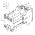
- a rail mounting structure for an electrical device is a structure in which an electromagnetic contactor 1 is mounted across a rail 2, as shown in FIG.
- the rail 2 includes a flat rail body 2a that is long in the left-right direction and extends in the vertical direction in the width direction, and an L-shaped rail body 2a extending from one edge in the width direction of the rail body 2a.
- An upper rail engaging portion 2b that protrudes upward and extends in the longitudinal direction (horizontal direction), and an L-shaped upper rail engagement portion 2b that protrudes downward from the other edge in the width direction of the rail body 2a and extends in the longitudinal direction.
- the lower rail engaging portion 2c is provided.
- the electromagnetic contactor 1 includes a first case 3 and a second case 4 as a housing made of insulating synthetic resin.
- the first case 3 houses an electromagnet and a drive lever that drive the contact portion.
- Main contact terminals 5a to 5c, auxiliary contact terminals (not shown), and electromagnetic coil terminals 5d and 5e are fixed to the second case 4, and a contact section including a movable contact and a fixed contact is provided inside the case. It is stored.
- FIG. 2 shows the bottom surface 3a of the first case 3 of the electromagnetic contactor 1 with the rail 2 removed, and a pair of upper device engaging portions 6 are formed at the top of the bottom surface 3a spaced apart in the left and right direction.
- a pair of lower device engaging portions 7 are provided at the lower part of the bottom surface 3a and spaced apart in the left-right direction, and extend linearly in the left-right direction on the bottom surface 3a above the pair of lower device engaging portions 7.
- a protruding portion 8 is formed.
- FIG. 3 shows the electromagnetic contactor 1 attached to the rail 2 from the left side, and the pair of upper device engaging parts 6 are arranged with a gap in which the upper rail engaging part 2b of the rail 2 fits. It is formed into a hook shape that opens downward along the bottom surface 3a.
- the pair of lower device engaging portions 7 are formed in a hook shape that opens upward along the bottom surface 3a while providing a gap into which the lower rail engaging portion 2c of the rail 2 fits.
- the protrusion 8 has a lower surface 8a that stands up substantially perpendicularly from the bottom surface 3a on the side close to the lower device engaging portion 7, and a slope that extends upward at an obtuse angle with respect to the lower surface 8a. It has a shape including a surface 8b.
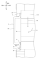
- FIG. 5 shows the electromagnetic contactor 1 attached to the rail 2 from the rear side, and a leaf spring 10 and a slider 11 are attached to the upper part of the bottom surface 3a.
- the leaf spring 10 is an elongated member formed by punching a metal plate material having spring properties, and is attached to a pair of leaf spring support parts 12a, 12b provided between a pair of upper device engaging parts 6 in a longitudinal direction. Both ends of the direction are supported.
- the slider 11 engages with the longitudinal center portion of the leaf spring 10 and is attached to be slidable in the vertical direction on the bottom surface 3a.
- the magnetic contactor 1 is connected to the rails with the upper rail engaging portions 2b being fitted into the pair of upper device engaging portions 6 and the lower rail engaging portions 2c being fitted into the pair of lower device engaging portions 7.
- the leaf spring 10 whose both ends are supported by the leaf spring supports 12a and 12b is elastically deformed upward into a convex shape.
- the downward spring biasing force Fb of the elastically deformed leaf spring 10 is transmitted to the upper rail engaging portion 2b via the slider 11.
- the electromagnetic contactor 1 moves upward relative to the rail 2
- the lower device engaging portion 7 engages the lower rail engaging portion 2c.
- the electromagnetic contactor 1 is attached to the rail 2 while being pressed upward.
- FIGS. 3, 6, and 7. a method for attaching the electromagnetic contactor 1 to the rail 2 will be described with reference to FIGS. 3, 6, and 7.
- the upper device engaging portion 6 of the electromagnetic contactor 1 is hooked onto the upper rail engaging portion 2b of the rail 2, and a load Fk is applied downward to the electromagnetic contactor 1 to engage the upper rail.
- the plate spring 10 is largely elastically deformed upward into a convex shape via the slider 11 in contact with the joint portion 2b.
- the lower rail engaging portion 2c of the rail 2 is positioned above the lower device engaging portion 7 of the electromagnetic contactor 1.
- the electromagnetic contactor 1 is rotated in the direction of arrow R centering on the upper equipment engaging part 6 side that is engaged with the upper rail engaging part 2b, and the lower rail of the rail 2 is rotated.
- the engaging portion 2c is brought into contact with the sloped surface 8b of the protrusion 8 formed on the bottom surface 3a of the electromagnetic contactor 1.
- the position of the opening 7a of the lower device engaging part 7 in the front-rear direction matches the lower rail engaging part 2c.
- the application of the load Fk downward to the electromagnetic contactor 1 is released.
- the downward spring biasing force Fb of the elastically deformed leaf spring 10 acts on the rail 2 via the slider 11, causing the electromagnetic contactor 1 to move relative to the rail 2. move upwards. Then, the lower device engaging portion 7 of the electromagnetic contactor 1 presses the lower rail engaging portion 2c upward, and the electromagnetic contactor 1 is attached across the rail 2.
- the impact force Fs that acts on the electromagnetic contactor 1 is a downward external force that acts on the electromagnetic contactor 1 when, for example, the electromagnetic contactor 1 to which the rail 2 is attached is dropped, and is shown in FIGS. 3 and 5. This force is larger than the spring urging force Fb generated by the leaf spring 10 when the electromagnetic contactor 1 is attached to the rail 2 (Fs>Fb).
- the protrusion 8 contacts the lower rail engaging portion 2c, and the electromagnetic contactor 1 is prevented by its own weight moment.
- the engagement state of the lower device engaging part 7 with the lower rail engaging part 2c is maintained, and the spring biasing force Fb of the leaf spring 10 is restored and acts on the rail 2.
- the lower device engaging portion 7 engages with the lower rail engaging portion 2c while pressing it upward. Therefore, the structure in which the electromagnetic contactor 1 of the first embodiment is attached to the rail 2 prevents the electromagnetic contactor 1 from falling off from the rail 2 even if a large impact force Fs is applied to the electromagnetic contactor 1.
- protrusion only one protrusion is provided on the bottom surface of the casing so as to extend in the left-right direction, but a plurality of protrusions may be provided in the left-right direction.
- shape of the protrusion is not limited to the shape of this embodiment.
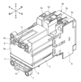
- FIGS. 10 to 12 are diagrams showing a rail mounting structure for an electric device according to a second embodiment of the present invention. Note that the same components as those of the rail mounting structure of the electrical equipment of the first embodiment shown in FIGS. 1 to 9 are given the same reference numerals, and the description thereof will be omitted.
- the electromagnetic contactor 20 of this embodiment has a groove portion extending linearly in the left-right direction on the bottom surface 3a of the first case 3 above the pair of lower device engaging portions 7. 13 is formed.
- the vertical width dimension Hm of the groove portion 13 is set larger than the vertical width dimension Hk of the lower rail engaging portion 2c of the rail 2 (Hm>Hk).
- the structure of attaching the electromagnetic contactor 20 of this embodiment to the rail 2 is such that the downward spring biasing force Fb of the elastically deformed leaf spring 10 acts on the rail 2 via the slider 11, By moving the electromagnetic contactor 20 upwards relative to the rail 2, the lower device engagement part 7 of the electromagnetic contactor 20 is in a state of pressing the lower rail engagement part 2c of the rail 2, and the electromagnetic contactor 20 is attached across the rail 2.
- the impact force Fs acting on the electromagnetic contactor 20 is also a force larger than the spring biasing force Fb generated by the leaf spring 10 (Fs>Fb), similarly to the first embodiment.
- the lower rail engaging part 2c that has come out of the lower equipment engaging part 7 causes the electromagnetic contactor 1 to move in the direction indicated by the arrow M2.
- the lower rail engaging portion that had entered the groove 13 enters into the groove 13 formed in the bottom surface 3a, and the spring biasing force Fb of the leaf spring 10 returns and acts on the rail 2.
- 2c is fitted into the lower equipment engaging portion 7 again, and the lower equipment engaging portion 7 engages with the lower rail engaging portion 2c while pressing it upward.
- the structure in which the electromagnetic contactor 20 of the second embodiment is attached to the rail 2 also prevents the electromagnetic contactor 20 from falling off from the rail 2 even if a large impact force Fs is applied to the electromagnetic contactor 20.
- both the protrusion of the first embodiment and the groove of the second embodiment may be provided on the bottom surface of the casing.
- Electromagnetic contactor 2 Rail 2a Rail main body 2b Upper rail engaging part 2c Lower rail engaging part 3 First case 3a Bottom surface (bottom surface of the housing) 4 Second case 5a to 5c Main contact terminals 5d, 5e Electromagnet coil terminal 6 Upper device engaging portion 7 Lower device engaging portion 7a Opening 8 Projection (engagement holding means) 8a Lower surface 8b Slope surface (interference prevention part) 10 Leaf spring (spring part) 11 Slider (spring part) 12a, 12b Leaf spring support section 13 Groove section (engagement holding means) Fb Spring biasing force Fk Load Fs Impact force
Landscapes
- Engineering & Computer Science (AREA)
- Power Engineering (AREA)
- Microelectronics & Electronic Packaging (AREA)
- Physics & Mathematics (AREA)
- Electromagnetism (AREA)
- Switch Cases, Indication, And Locking (AREA)
Abstract
幅方向の両端に上部レール係合部(2b)及び下部レール係合部(2c)を設けたレール(2)と、筐体底面(3a)の上下に対峙したフック形状の上部機器係合部(6)及び下部機器係合部(7)を設け、上部レール係合部が上部機器係合部に嵌まり込んで係合し、下部レール係合部が下部機器係合部に嵌まり込んで係合する電気機器(1)と、筐体底面の上部機器係合部の近傍に配置され、上部機器係合部に係合する上部レール係合部にばね付勢力を作用させるばね部(10),(11)と、ばね付勢力より大きな衝撃力が電気機器に加わった際に、下部レール係合部及び下部機器係合部の係合状態を保持する係合保持手段(8)と、を備えている。
Description
本発明は、配線用回路遮断器、電磁接触器などの電気機器をレールに取付ける電気機器のレール取付け構造に関する。
従来、電気機器のレール取付け構造として、例えば、特許文献1に示す技術が知られている。
この特許文献1の電気機器は、レールの幅方向の両端に設けた第1レール部及び第2レール部に係合して取付けられる。電気機器の筐体底部には、互いに対峙したフック形状の第1係合部及び第2係合部が形成されており、第1係合部が第1レール部に係合し、第2係合部が第2レール部に係合している。また、電気機器の筐体底面には、ばね部材が装着されており、ばね部材のばね付勢力が第1係合部に係合している第1レール部に作用することで、電気機器をレールに対して相対移動させる。この電気機器の相対移動により第2係合部が第2レール部を押圧した状態とし、電気機器がレールに跨がった状態で取り付けられる。
この特許文献1の電気機器は、レールの幅方向の両端に設けた第1レール部及び第2レール部に係合して取付けられる。電気機器の筐体底部には、互いに対峙したフック形状の第1係合部及び第2係合部が形成されており、第1係合部が第1レール部に係合し、第2係合部が第2レール部に係合している。また、電気機器の筐体底面には、ばね部材が装着されており、ばね部材のばね付勢力が第1係合部に係合している第1レール部に作用することで、電気機器をレールに対して相対移動させる。この電気機器の相対移動により第2係合部が第2レール部を押圧した状態とし、電気機器がレールに跨がった状態で取り付けられる。
ところで、特許文献1の構造は、第2係合部が第2レール部を押圧している方向に対して逆向きの大きな衝撃力が電気機器に加わると、第2係合部が第2レールから外れてしまい、電気機器がレールから脱落するおそれがある。
本発明はこれら従来の問題点を解決するためになされたものであり、その目的は、電気機器に衝撃力が加わってもレールから脱落するおそれがない電気機器のレール取付け構造を提供することにある。
本発明はこれら従来の問題点を解決するためになされたものであり、その目的は、電気機器に衝撃力が加わってもレールから脱落するおそれがない電気機器のレール取付け構造を提供することにある。
上記目的を達成するために、本発明の一態様に係る電気機器のレール取付け構造は、電気機器を、レールに跨って取り付ける電気機器のレール取付け構造であって、幅方向の両端に上部レール係合部及び下部レール係合部を設けたレールと、筐体底面の上下に対峙したフック形状の上部機器係合部及び下部機器係合部を設け、上部レール係合部が上部機器係合部に嵌まり込んで係合し、下部レール係合部が下部機器係合部に嵌まり込んで係合する電気機器と、筐体底面の上部機器係合部の近傍に配置され、上部機器係合部に係合する上部レール係合部にばね付勢力を作用させるばね部と、ばね付勢力より大きな衝撃力が電気機器に加わった際に、下部レール係合部及び下部機器係合部の係合状態を保持する係合保持手段と、を備えている。
本発明の電気機器のレール取付け構造によれば、電気機器に衝撃力が加わってもレールから脱落するおそれがない。
次に、図面を参照して、本発明に係る実施形態を説明する。以下の図面の記載において、同一又は類似の部分には同一又は類似の符号を付している。ただし、図面は模式的なものであり、厚みと平面寸法との関係、各層の厚みの比率等は現実のものとは異なることに留意すべきである。したがって、具体的な厚みや寸法は以下の説明を参酌して判断すべきものである。また、図面相互間においても互いの寸法の関係や比率が異なる部分が含まれていることはもちろんである。
また、以下に示す実施形態は、本発明の技術的思想を具体化するための装置や方法を例示するものであって、本発明の技術的思想は、構成部品の材質、形状、構造、配置等を下記のものに特定するものでない。本発明の技術的思想は、特許請求の範囲に記載された請求項が規定する技術的範囲内において、種々の変更を加えることができる。
なお、以下の説明で記載されている「上」、「下」、「前」、「後」、「左」、「右」等の方向を示す用語は、添付図面の方向を参照して用いられている。
なお、以下の説明で記載されている「上」、「下」、「前」、「後」、「左」、「右」等の方向を示す用語は、添付図面の方向を参照して用いられている。
[第1実施形態]
本発明に係る第1実施形態の電気機器のレール取付け構造は、図1に示すように、電磁接触器1をレール2に跨って取り付ける構造である。
レール2は、図1に示すように、左右方向に長尺で上下方向に幅方向が延在している平板形状のレール本体2aと、レール本体2aの幅方向の一方の縁部からL字形状に上方に突出して長手方向(左右方向)に延在している上部レール係合部2bと、レール本体2aの幅方向の他方の縁部からL字形状に下方に突出して長手方向に延在している下部レール係合部2cと、を備えている。
本発明に係る第1実施形態の電気機器のレール取付け構造は、図1に示すように、電磁接触器1をレール2に跨って取り付ける構造である。
レール2は、図1に示すように、左右方向に長尺で上下方向に幅方向が延在している平板形状のレール本体2aと、レール本体2aの幅方向の一方の縁部からL字形状に上方に突出して長手方向(左右方向)に延在している上部レール係合部2bと、レール本体2aの幅方向の他方の縁部からL字形状に下方に突出して長手方向に延在している下部レール係合部2cと、を備えている。
電磁接触器1は、絶縁性を有する合成樹脂で形成された筐体としての第1ケース3及び第2ケース4を備えている。第1ケース3には、接点部を駆動させる電磁石及び駆動レバーが収納されている。第2ケース4には、主接点端子5a~5c、補助接点端子(不図示)及び電磁石のコイル端子5d,5eが固定されているとともに、ケース内部に可動接点及び固定接点を備えた接点部が収納されている。
図2は、レール2を取り外した状態の電磁接触器1の第1ケース3の底面3aを示すものであり、底面3aの上部に左右方向に離間して一対の上部機器係合部6が形成され、底面3aの下部に左右方向に離間して一対の下部機器係合部7が設けられているとともに、一対の下部機器係合部7より上方の底面3aで左右方向に直線状に延在して突起部8が形成されている。
図3は、レール2に取付けられた電磁接触器1を左側から示したものであり、一対の上部機器係合部6は、レール2の上部レール係合部2bが嵌まり込む隙間を設けながら底面3aに沿って下方を向いて開口するフック形状に形成されている。また、一対の下部機器係合部7は、レール2の下部レール係合部2cが嵌まり込む隙間を設けながら底面3aに沿って上方を向いて開口するフック形状に形成されている。
突起部8は、図4に示すように、下部機器係合部7に近接する側で底面3aから略直交して立ち上がる下面8aと、下面8aに対して鈍角をなして上方に延在する勾配面8bと、を備えた形状としている。
突起部8は、図4に示すように、下部機器係合部7に近接する側で底面3aから略直交して立ち上がる下面8aと、下面8aに対して鈍角をなして上方に延在する勾配面8bと、を備えた形状としている。
図5は、レール2に取付けられた電磁接触器1を後ろ側から示したものであり、底面3aの上部には板ばね10及びスライダ11が装着されている。板ばね10は、ばね性を有する金属板材を打ち抜き加工することによって形成された長尺部材であり、一対の上部機器係合部6の間に設けた一対の板ばね支持部12a,12bに長手方向の両端部が支持されている。スライダ11は、板ばね10の長手方向中央部に係合し、底面3a上を上下方向に摺動可能に取付けられている。そして、一対の上部機器係合部6に上部レール係合部2bが嵌まり込み、一対の下部機器係合部7に下部レール係合部2cが嵌まり込んだ状態で電磁接触器1をレール2に取付けると、板ばね支持部12a,12bに両端が支持された板ばね10が上方に向けて凸形状に弾性変形する。そして、図3及び図5に示すように、弾性変形した板ばね10の下方を向くばね付勢力Fbが、スライダ11を介して上部レール係合部2bに伝達される。この板ばね10のばね付勢力Fbがレール2に伝達されることで電磁接触器1がレール2に対して相対的に上方に移動し、下部機器係合部7が下部レール係合部2cを上方に押圧した状態とし、電磁接触器1がレール2に跨って取り付けられる。
次に、電磁接触器1をレール2に取り付ける方法について図3、図6及び図7を参照して説明する。
先ず、図6に示すように、電磁接触器1の上部機器係合部6をレール2の上部レール係合部2bに引っ掛け、電磁接触器1に下方に荷重Fkを加えることで、上部レール係合部2bに当接したスライダ11を介して板ばね10を上方に向けて凸形状に大きく弾性変形させる。そして、レール2の下部レール係合部2cを、電磁接触器1の下部機器係合部7の上方に位置させる。
先ず、図6に示すように、電磁接触器1の上部機器係合部6をレール2の上部レール係合部2bに引っ掛け、電磁接触器1に下方に荷重Fkを加えることで、上部レール係合部2bに当接したスライダ11を介して板ばね10を上方に向けて凸形状に大きく弾性変形させる。そして、レール2の下部レール係合部2cを、電磁接触器1の下部機器係合部7の上方に位置させる。
次いで、図7に示すように、上部レール係合部2bに係合している上部機器係合部6側を中心として電磁接触器1を矢印R方向に回転させていき、レール2の下部レール係合部2cを、電磁接触器1の底面3aに形成した突起部8の勾配面8bに当接させる。これにより、下部レール係合部2cに対して下部機器係合部7の開口部7aの前後方向の位置が一致する。
次いで、電磁接触器1に対して下方へ荷重Fkを加えるのを解除する。この動作を行うと、図3に示すように、弾性変形した板ばね10の下方を向くばね付勢力Fbがスライダ11を介してレール2に作用し、レール2に対して電磁接触器1が相対的に上方へ移動する。そして、電磁接触器1の下部機器係合部7が下部レール係合部2cを上方に押圧した状態とし、電磁接触器1がレール2に跨って取り付けられる。
次いで、電磁接触器1に対して下方へ荷重Fkを加えるのを解除する。この動作を行うと、図3に示すように、弾性変形した板ばね10の下方を向くばね付勢力Fbがスライダ11を介してレール2に作用し、レール2に対して電磁接触器1が相対的に上方へ移動する。そして、電磁接触器1の下部機器係合部7が下部レール係合部2cを上方に押圧した状態とし、電磁接触器1がレール2に跨って取り付けられる。
一方、レール2から電磁接触器1を取外すには、図7で示した電磁接触器1に下方に荷重Fkを加えることで、下部機器係合部7の下部レール係合部2cに対する係合状態を解除し、次いで、上部機器係合部6の上部レール係合部2bに対する係合状態を解除する。これにより、電磁接触器1がレール2から取り外される。
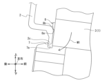
次に、レール2に取付けられている電磁接触器1に対して下向きの衝撃力が作用した場合の動作について、図8及び図9を参照して説明する。電磁接触器1に作用する衝撃力Fsは、例えばレール2を組付けている電磁接触器1を落下した場合に電磁接触器1に作用する下向きの外力であり、図3及び図5で示した電磁接触器1がレール2に取付ける際に板ばね10が発生するばね付勢力Fbより大きな力である(Fs>Fb)。
次に、レール2に取付けられている電磁接触器1に対して下向きの衝撃力が作用した場合の動作について、図8及び図9を参照して説明する。電磁接触器1に作用する衝撃力Fsは、例えばレール2を組付けている電磁接触器1を落下した場合に電磁接触器1に作用する下向きの外力であり、図3及び図5で示した電磁接触器1がレール2に取付ける際に板ばね10が発生するばね付勢力Fbより大きな力である(Fs>Fb)。
図8に示すように、電磁接触器1に下向きの衝撃力Fsが作用すると、レール2に対して電磁接触器1が相対的に下方へ移動する。これにより、レール2の下部レール係合部2cが下部機器係合部7から抜け出ようとするが、下部レール係合部2cの上部が突起部8の下面8a、或いは勾配面8bの一部に当接することで、下部レール係合部2cが下部機器係合部7から抜け出ない。次いで、図9に示すように、電磁接触器1の自重モーメントにより電磁接触器1が矢印M1方向に回転すると、下部レール係合部2cが突起部8に押され、下部レール係合部2cの先端部が下部機器係合部7の開口部7aに係合する。そして、板ばね10のばね付勢力Fbが復帰してレール2に作用することで、レール2に対して電磁接触器1が相対的に上方へ移動していき、下部機器係合部7が下部レール係合部2cを上方に押圧した状態で係合が保持される。
このように、第1実施形態によれば、電磁接触器1に下向きの衝撃力Fsが作用しても、突起部8が下部レール係合部2cに当接し、自重モーメントで電磁接触器1が矢印M1方向に回転することで、下部レール係合部2cに対する下部機器係合部7の係合状態が保持され、板ばね10のばね付勢力Fbが復帰してレール2に作用することで、下部機器係合部7が下部レール係合部2cを上方に押圧した状態で係合する。したがって、第1実施形態の電磁接触器1をレール2に取り付ける構造は、大きな衝撃力Fsが電磁接触器1に加わってもレール2から電磁接触器1が脱落するおそれがない。
なお、本実施形態では、突起部を筐体底面に左右方向に延びるように一つだけ設けるようにしたが、左右方向に複数個設けるようにしてもよい。また、突起部の形状も本実施形態の形状に限定されない。
なお、本実施形態では、突起部を筐体底面に左右方向に延びるように一つだけ設けるようにしたが、左右方向に複数個設けるようにしてもよい。また、突起部の形状も本実施形態の形状に限定されない。
[第2実施形態]
次に、図10~図12は、本発明に係る第2実施形態の電気機器のレール取付け構造を示す図である。なお、図1~図9で示した第1実施形態の電気機器のレール取付け構造と同一構成部分には、同一符号を付して説明は省略する。
本実施形態の電磁接触器20は、図10に示すように、第1ケース3の底面3aに、一対の下部機器係合部7より上方の底面3aで左右方向に直線状に延在する溝部13が形成されている。図11に示すように、溝部13の上下方向の幅寸法Hmは、レール2の下部レール係合部2cの上下方向の幅寸法Hkより大きく設定されている(Hm>Hk)。
次に、図10~図12は、本発明に係る第2実施形態の電気機器のレール取付け構造を示す図である。なお、図1~図9で示した第1実施形態の電気機器のレール取付け構造と同一構成部分には、同一符号を付して説明は省略する。
本実施形態の電磁接触器20は、図10に示すように、第1ケース3の底面3aに、一対の下部機器係合部7より上方の底面3aで左右方向に直線状に延在する溝部13が形成されている。図11に示すように、溝部13の上下方向の幅寸法Hmは、レール2の下部レール係合部2cの上下方向の幅寸法Hkより大きく設定されている(Hm>Hk)。
本実施形態の電磁接触器20をレール2に取り付ける構造は、第1実施形態と同様に、弾性変形した板ばね10の下方を向くばね付勢力Fbがスライダ11を介してレール2に作用し、レール2に対して電磁接触器20を相対的に上方へ移動することで、電磁接触器20の下部機器係合部7がレール2の下部レール係合部2cを押圧した状態とし、電磁接触器20がレール2に跨って取り付けられている。
次に、レール2に取付けられている電磁接触器20に対して下向きの衝撃力が作用した場合の動作について、図12を参照して説明する。電磁接触器20に作用する衝撃力Fsも、第1実施形態と同様に、板ばね10が発生するばね付勢力Fbより大きな力である(Fs>Fb)。
次に、レール2に取付けられている電磁接触器20に対して下向きの衝撃力が作用した場合の動作について、図12を参照して説明する。電磁接触器20に作用する衝撃力Fsも、第1実施形態と同様に、板ばね10が発生するばね付勢力Fbより大きな力である(Fs>Fb)。
先ず、電磁接触器1に下向きの衝撃力Fsが作用すると、レール2に対して電磁接触器1が相対的に下方へ移動する。これにより、レール2の下部レール係合部2cが下部機器係合部7から抜け出る。次いで、電磁接触器1の自重モーメントにより電磁接触器1が矢印M2方向に回転すると、下部レール係合部2cが底面3aに形成した溝部13に入り込んだ状態となる。そして、下部レール係合部2cが溝部13に入り込んでいるときに、板ばね10のばね付勢力Fbが復帰してレール2に作用する。板ばね10のばね付勢力Fbがレール2に作用してレール2に対して電磁接触器1が相対的に上方へ移動していくことで、下部レール係合部2cが下部機器係合部7に嵌まり込んでいき、下部機器係合部7が下部レール係合部2cを上方に押圧した状態で係合が保持される。
このように、第2実施形態によれば、電磁接触器1に下向きの衝撃力Fsが作用すると、下部機器係合部7から抜け出た下部レール係合部2cが、電磁接触器1が矢印M2方向に回転することで底面3aに形成した溝部13に入り込んだ状態となり、板ばね10のばね付勢力Fbが復帰してレール2に作用することで、溝部13に入り込んでいた下部レール係合部2cが、再度、下部機器係合部7に嵌まり込み、下部機器係合部7が下部レール係合部2cを上方に押圧した状態で係合する。したがって、第2実施形態の電磁接触器20をレール2に取り付ける構造も、大きな衝撃力Fsが電磁接触器20に加わってもレール2から電磁接触器20が脱落するおそれがない。
なお、第1実施形態の突起部と、第2実施形態の溝部を筐体底面に両方設けるようにしてよい。
なお、第1実施形態の突起部と、第2実施形態の溝部を筐体底面に両方設けるようにしてよい。
1,20 電磁接触器
2 レール
2a レール本体
2b 上部レール係合部
2c 下部レール係合部
3 第1ケース
3a 底面(筐体底面)
4 第2ケース
5a~5c 主接点端子
5d,5e 電磁石のコイル端子
6 上部機器係合部
7 下部機器係合部
7a 開口部
8 突起部(係合保持手段)
8a 下面
8b 勾配面(干渉防止部)
10 板ばね(ばね部)
11 スライダ(ばね部)
12a,12b 板ばね支持部
13 溝部(係合保持手段)
Fb ばね付勢力
Fk 荷重
Fs 衝撃力
2 レール
2a レール本体
2b 上部レール係合部
2c 下部レール係合部
3 第1ケース
3a 底面(筐体底面)
4 第2ケース
5a~5c 主接点端子
5d,5e 電磁石のコイル端子
6 上部機器係合部
7 下部機器係合部
7a 開口部
8 突起部(係合保持手段)
8a 下面
8b 勾配面(干渉防止部)
10 板ばね(ばね部)
11 スライダ(ばね部)
12a,12b 板ばね支持部
13 溝部(係合保持手段)
Fb ばね付勢力
Fk 荷重
Fs 衝撃力
Claims (4)
- 電気機器を、レールに跨って取り付ける電気機器のレール取付け構造であって、
幅方向の両端に上部レール係合部及び下部レール係合部を設けたレールと、
筐体底面の上下に対峙したフック形状の上部機器係合部及び下部機器係合部を設け、前記上部レール係合部が前記上部機器係合部に嵌まり込んで係合し、前記下部レール係合部が前記下部機器係合部に嵌まり込んで係合する電気機器と、
前記筐体底面の前記上部機器係合部の近傍に配置され、
前記上部機器係合部に係合する前記上部レール係合部にばね付勢力を作用させるばね部と、
前記ばね付勢力より大きな衝撃力が前記電気機器に加わった際に、前記下部レール係合部及び前記下部機器係合部の係合状態を保持する係合保持手段と、を備えていることを特徴とする電気機器のレール取付け構造。 - 前記係合保持手段は、前記筐体底面から突出して形成され、前記衝撃力が前記電気機器に加わった際に、前記下部レール係合部の一部が当接することで、前記下部レール係合部が前記下部機器係合部から抜け出るのを規制する突起部であることを特徴とする請求項1記載の電気機器のレール取付け構造。
- 前記突起部は、前記下部レール係合部を前記下部機器係合部に係合するとき、或いは前記下部レール係合部を前記下部機器係合部から外すときに、前記下部レール係合部との干渉を防止する干渉防止部を設けていることを特徴とする請求項2記載の電気機器のレール取付け構造。
- 前記係合保持手段は、前記筐体底面に凹んで形成され、前記衝撃力が前記電気機器に加わった際に、前記下部レール係合部の一部が入り込むことで、前記下部レール係合部が前記下部機器係合部から抜け出るのを規制する溝部であることを特徴とする請求項1記載の電気機器のレール取付け構造。
Applications Claiming Priority (2)
| Application Number | Priority Date | Filing Date | Title |
|---|---|---|---|
| JP2022121392 | 2022-07-29 | ||
| JP2022-121392 | 2022-07-29 |
Publications (1)
| Publication Number | Publication Date |
|---|---|
| WO2024024143A1 true WO2024024143A1 (ja) | 2024-02-01 |
Family
ID=89705912
Family Applications (1)
| Application Number | Title | Priority Date | Filing Date |
|---|---|---|---|
| PCT/JP2023/006285 WO2024024143A1 (ja) | 2022-07-29 | 2023-02-21 | 電気機器のレール取付け構造 |
Country Status (1)
| Country | Link |
|---|---|
| WO (1) | WO2024024143A1 (ja) |
Citations (7)
| Publication number | Priority date | Publication date | Assignee | Title |
|---|---|---|---|---|
| JPS509756U (ja) * | 1973-05-24 | 1975-01-31 | ||
| JPS54179457U (ja) * | 1978-06-08 | 1979-12-19 | ||
| JP2003152353A (ja) * | 2001-11-12 | 2003-05-23 | Digital Electronics Corp | レール取付機構 |
| JP2007194318A (ja) * | 2006-01-18 | 2007-08-02 | Omron Corp | Dinレール取付け型電気機器の取付け構造 |
| US7374453B1 (en) * | 2006-12-28 | 2008-05-20 | General Electric Company | Enclosure-to-rail retaining system and method |
| JP2014120357A (ja) * | 2012-12-18 | 2014-06-30 | Fuji Electric Fa Components & Systems Co Ltd | 電気機器のレール装着装置及びこれを使用した熱動形過負荷継電器 |
| CN211090249U (zh) * | 2019-12-09 | 2020-07-24 | 索提斯云智控科技(上海)有限公司 | 一种用于固定可编程逻辑控制器的卡扣机构 |
-
2023
- 2023-02-21 WO PCT/JP2023/006285 patent/WO2024024143A1/ja unknown
Patent Citations (7)
| Publication number | Priority date | Publication date | Assignee | Title |
|---|---|---|---|---|
| JPS509756U (ja) * | 1973-05-24 | 1975-01-31 | ||
| JPS54179457U (ja) * | 1978-06-08 | 1979-12-19 | ||
| JP2003152353A (ja) * | 2001-11-12 | 2003-05-23 | Digital Electronics Corp | レール取付機構 |
| JP2007194318A (ja) * | 2006-01-18 | 2007-08-02 | Omron Corp | Dinレール取付け型電気機器の取付け構造 |
| US7374453B1 (en) * | 2006-12-28 | 2008-05-20 | General Electric Company | Enclosure-to-rail retaining system and method |
| JP2014120357A (ja) * | 2012-12-18 | 2014-06-30 | Fuji Electric Fa Components & Systems Co Ltd | 電気機器のレール装着装置及びこれを使用した熱動形過負荷継電器 |
| CN211090249U (zh) * | 2019-12-09 | 2020-07-24 | 索提斯云智控科技(上海)有限公司 | 一种用于固定可编程逻辑控制器的卡扣机构 |
Similar Documents
| Publication | Publication Date | Title |
|---|---|---|
| JP5104827B2 (ja) | 電気機器のレール取付け構造 | |
| KR101552189B1 (ko) | 전기 커넥터 | |
| KR20130128314A (ko) | 전기 커넥터 | |
| JP2006040832A (ja) | 電気コネクタ | |
| JPS60143539A (ja) | リレ−およびリレ−の製造方法 | |
| WO2024024143A1 (ja) | 電気機器のレール取付け構造 | |
| JPH05315035A (ja) | 電気部品用ソケットにおける接触保持装置 | |
| CN1790580A (zh) | 电磁继电器 | |
| EP0182361B1 (en) | Large picture display device | |
| US6781850B2 (en) | Protection against folding and displacement for a flexible printed circuit board in a contact-making region | |
| GB2075263A (en) | Electric control device | |
| JP6587013B1 (ja) | 電気機器のレール取付け構造 | |
| JPH0451509Y2 (ja) | ||
| JPH07122171A (ja) | 回路遮断器の取付装置 | |
| JP4683564B2 (ja) | レール取付け構造 | |
| JP3953001B2 (ja) | 電気機器のレール取付け構造 | |
| JPH0132280Y2 (ja) | ||
| EP4336538A1 (en) | Electromagnet device and electromagnetic relay | |
| JPH0140262Y2 (ja) | ||
| JPH04121639U (ja) | 電磁接触器 | |
| JPH08242087A (ja) | プラグインレール | |
| JPH0129705Y2 (ja) | ||
| JP2009140900A (ja) | 据付レール用固定金具 | |
| JP3279060B2 (ja) | 速結端子台 | |
| WO2012057304A1 (ja) | コネクタ |
Legal Events
| Date | Code | Title | Description |
|---|---|---|---|
| 121 | Ep: the epo has been informed by wipo that ep was designated in this application |
Ref document number: 23845883 Country of ref document: EP Kind code of ref document: A1 |