WO2024023964A1 - オイルシール外し治具 - Google Patents
オイルシール外し治具 Download PDFInfo
- Publication number
- WO2024023964A1 WO2024023964A1 PCT/JP2022/028906 JP2022028906W WO2024023964A1 WO 2024023964 A1 WO2024023964 A1 WO 2024023964A1 JP 2022028906 W JP2022028906 W JP 2022028906W WO 2024023964 A1 WO2024023964 A1 WO 2024023964A1
- Authority
- WO
- WIPO (PCT)
- Prior art keywords
- handle
- oil seal
- blade
- removal jig
- fulcrum
- Prior art date
- Legal status (The legal status is an assumption and is not a legal conclusion. Google has not performed a legal analysis and makes no representation as to the accuracy of the status listed.)
- Ceased
Links
Images





Classifications
-
- B—PERFORMING OPERATIONS; TRANSPORTING
- B25—HAND TOOLS; PORTABLE POWER-DRIVEN TOOLS; MANIPULATORS
- B25B—TOOLS OR BENCH DEVICES NOT OTHERWISE PROVIDED FOR, FOR FASTENING, CONNECTING, DISENGAGING, OR HOLDING
- B25B27/00—Hand tools, specially adapted for fitting together or separating parts or objects whether or not involving some deformation, not otherwise provided for
- B25B27/14—Hand tools, specially adapted for fitting together or separating parts or objects whether or not involving some deformation, not otherwise provided for for assembling objects other than by press fit or detaching same
- B25B27/28—Hand tools, specially adapted for fitting together or separating parts or objects whether or not involving some deformation, not otherwise provided for for assembling objects other than by press fit or detaching same positioning or withdrawing resilient bushings or the like
Definitions
- the present disclosure relates to an oil seal removal jig.
- a conventional oil seal removal tool includes a tool body and a claw.
- the tool body is provided with a through hole and a fulcrum.
- the pawl is fixed to the tool body.
- the present disclosure has been made to solve the above-mentioned problems, and aims to provide an oil seal removal jig that can more easily remove an oil seal.
- the oil seal removal device includes a handle that is held by an operator, a blade that is provided at the tip of the handle and that pierces the oil seal, and a blade that is provided in the middle of the handle, and It is provided with a fulcrum body that protrudes in a direction perpendicular to the longitudinal direction of the handle and serves as a fulcrum when rotating the handle by being applied to a portion to which an oil seal is attached.
- the oil seal removal jig of the present disclosure the oil seal can be removed more easily.
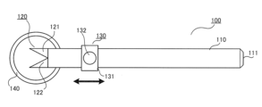
- FIG. 3 is a plan view showing an oil seal removal jig in Embodiment 1.
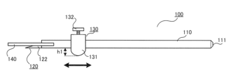
- FIG. FIG. 2 is a side view showing the oil seal removal jig of FIG. 1;
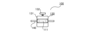
- FIG. 2 is a bottom view showing the oil seal removal jig of FIG. 1;
- FIG. 2 is a front view showing the oil seal removal jig shown in FIG. 1;
- FIG. 2 is a rear view showing the oil seal removal jig of FIG. 1;
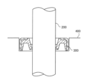
- FIG. 3 is a cross-sectional view showing an oil seal, a shaft member, and a mounted portion in the first embodiment.
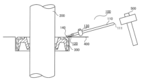
- FIG. 2 is an explanatory diagram showing a state when the blade portion of the oil seal removal jig shown in FIG. 1 is pierced into an oil seal.
- FIG. 2 is an explanatory diagram showing a state when the blade portion of the oil seal removal jig shown in FIG. 1 is pierced into an oil seal.
- FIG. 2 is an explanatory diagram showing a state when rotating the handle of the oil seal removal jig shown in FIG. 1;
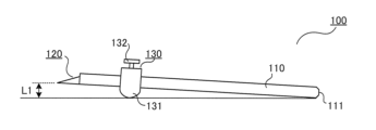
- FIG. 2 is a side view showing a state in which the blade portion of the oil seal removal jig shown in FIG. 1 is lifted;
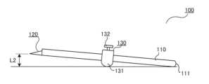
- 10 is a side view showing a state in which the fulcrum body is moved away from the blade part from the state shown in FIG. 9.
- FIG. 11 is a side view showing a state when the blade portion is lifted from the state shown in FIG. 10.
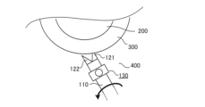
- FIG. It is a top view which shows only a 1st blade sticking into an oil seal and rotating a handle. It is a top view which shows the state when the blade which pierces an oil seal is switched from a 1st blade to a 2nd blade.
- FIG. 14 is a plan view showing the reverse rotation of the handle from the state shown in FIG. 13;
- FIG. 6 is a side view showing the oil seal removal jig when another fulcrum body is attached.
- FIG. 1 is a plan view showing an oil seal removal jig in the first embodiment.
- 2 is a side view showing the oil seal removal jig of FIG. 1.
- FIG. 3 is a bottom view of the oil seal removal jig shown in FIG. 1.
- FIG. 4 is a front view showing the oil seal removal jig of FIG. 1.
- 5 is a rear view of the oil seal removal jig shown in FIG. 1.
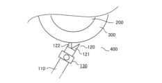
- FIG. FIG. 6 is a side view showing an oil seal, a shaft member, and a mounted portion in the first embodiment.
- an oil seal removal jig 100 is used to remove the oil seal 300 shown in FIG. 6 from the mounted portion 400 along the shaft member 200.
- the shaft member 200 is, for example, the main shaft of an elevator hoist (not shown).
- the mounted portion 400 is a part of the hoisting machine that supports the main shaft.
- the oil seal 300 is attached to the attached portion 400 .
- the oil seal 300 is an annular member made of rubber, and prevents the lubricant applied inside the hoisting machine from flowing out.
- the oil seal removal jig 100 includes a handle 110, a blade portion 120, a fulcrum 130, and a protection member 140.
- the handle 110 is a member that is held by the operator.
- the blade portion 120 is provided at the tip of the handle 110. Further, an end 111 of the handle 110 opposite to the tip is chamfered.
- the blade portion 120 is a portion that pierces the oil seal 300, and includes a first blade 121 and a second blade 122.
- the first blade 121 projects obliquely from the tip of the handle 110 with respect to the longitudinal direction of the handle 110.
- the second blade 122 projects from the tip of the handle 110 in a direction different from that of the first blade 121, diagonally with respect to the longitudinal direction of the handle 110.
- the fulcrum body 130 is provided at the middle part of the handle 110.
- the fulcrum body 130 protrudes in a direction perpendicular to the longitudinal direction of the handle 110. As shown in FIG. 2, the amount of protrusion of the fulcrum body 130 from the handle 110 is h1.
- the fulcrum body 130 serves as a fulcrum when rotating the handle 110 by being applied to the mounted portion 400 .
- the fulcrum body 130 has a fulcrum body portion 131 and a fastener 132.
- the fastener 132 fixes the position of the fulcrum main body part 131 with respect to the handle 110.
- the fastener 132 is loosened, the fulcrum main body portion 131 becomes movable in the longitudinal direction of the handle 110.
- the fulcrum body 130 is attached to the handle 110 so that its position in the longitudinal direction of the handle 110 can be adjusted.
- the protection member 140 is a member that protects the blade portion 120.
- the protection member 140 is an annular member made of rubber and is fixed to the handle 110.
- the protection member 140 is pressed against the oil seal 300 and elastically deforms before the blade portion 120 comes into contact with the oil seal 300. Note that depending on the orientation of the oil seal removal jig 100, the protection member 140 may be pressed against the mounted portion 400 and elastically deformed.
- FIG. 7 is an explanatory diagram showing a state when the blade portion 120 of the oil seal removal jig 100 of FIG. 1 is pierced into the oil seal 300.
- the direction in which the oil seal 300 is removed will be referred to as a first direction, and the opposite direction will be referred to as a second direction.
- the operator places the tip of the blade portion 120 against the oil seal 300. Then, by hitting the end portion 111 with the hammer 500, the blade portion 120 pierces the oil seal 300.
- FIG. 8 is an explanatory diagram showing a state when rotating the handle 110 in the oil seal removal jig 100 of FIG. 1.
- the operator places the bottom of the fulcrum body 130 on the mounted portion 400 and rotates the handle 110. As a result, the blade portion 120 is lifted in the first direction, and the oil seal 300 is removed from the attached portion 400.
- FIG. 9 is a side view showing a state in which the blade portion 120 of the oil seal removal jig 100 of FIG. 1 is lifted in the first direction.
- FIG. 10 is a side view showing a state in which the fulcrum body 130 is moved away from the blade portion 120 from the state shown in FIG.
- FIG. 11 is a side view showing the state when the blade portion 120 is lifted in the first direction from the state shown in FIG. Note that the oil seal 300 is not illustrated in FIGS. 9 to 11.
- the operator thrusts the blade 120 into the oil seal 300, rotates the handle 110, and lifts the blade 120 in the first direction. Let the lifting height at this time be L1.
- the operator rotates the handle 110 to further lift the blade portion 120 in the first direction.
- the blade portion 120 is lifted up to a lifting height L2 higher than the lifting height L1.
- FIG. 12 is a plan view showing how the handle 110 is rotated by piercing only the first blade 121 into the oil seal 300.
- FIG. 13 is a plan view showing a state when the blade piercing the oil seal 300 is switched from the first blade 121 to the second blade 122.
- FIG. 14 is a plan view showing reverse rotation of the handle 110 from the state shown in FIG. 13.
- the operator pierces only the first blade 121 into the oil seal 300, and then puts the bottom of the fulcrum body 130 against the mounted portion 400. Then, the operator rotates the handle 110 using the longitudinal direction of the handle 110 as the rotation axis so as to lift the first blade 121 in the first direction. This rotation lifts the oil seal 300 using the fulcrum body 130 as a fulcrum.
- the operator pulls out the first blade 121 from the oil seal 300 while piercing the second blade 122 into the oil seal 300. At this time, the operator pierces the second blade 122 at a position in the second direction from the position where the first blade 121 was pierced.
- the operator rotates the handle 110 in a direction that lifts the second blade 122 in the first direction. This rotation further lifts the oil seal 300 using the fulcrum body 130 as a fulcrum.
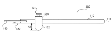
- FIG. 15 is a side view showing the oil seal removal jig 100 when another fulcrum body is attached.
- the fulcrum body 130 and the other fulcrum body 130a are each removable from the end portion 111 of the handle 110. Therefore, the fulcrum body 130 can be replaced with another fulcrum body 130a.
- the amount of protrusion of the other fulcrum body 130a from the handle 110 is h2.
- the protrusion amount h2 is different from the protrusion amount h1.
- the protrusion amount h2 is longer than the protrusion amount h1.
- the oil seal removal jig 100 of the first embodiment includes a blade portion 120 and a fulcrum body 130.
- the blade portion 120 is provided at the tip of the handle 110 and is pierced into the oil seal 300.
- the fulcrum body 130 is provided at an intermediate portion of the handle 110 and protrudes in a direction perpendicular to the longitudinal direction of the handle 110. Further, the fulcrum body 130 serves as a fulcrum when rotating the handle 110 by being applied to the mounted portion 400 to which the oil seal 300 is mounted.
- the oil seal 300 can be removed more easily.
- the fulcrum body 130 is attached to the handle 110 so that its position in the longitudinal direction of the handle 110 can be adjusted. Therefore, the lifting height of the blade portion 120 when the handle 110 is rotated can be adjusted.
- the blade portion 120 has a first blade 121 that projects obliquely from the tip of the handle 110 with respect to the longitudinal direction of the handle 110. Further, the blade portion 120 has a second blade 122 that protrudes from the tip of the handle 110 in a direction different from the first blade 121, diagonally with respect to the longitudinal direction of the handle 110. Therefore, the load applied to the blade portion 120 when lifting the oil seal 300 can be dispersed.
- the oil seal removal jig 100 further includes another fulcrum body 130a whose protrusion amount from the handle 110 is different from that of the fulcrum body 130. Further, the fulcrum body 130 and the other fulcrum body 130a are each removable from the handle 110. Therefore, by replacing the fulcrum body 130, the lifting height of the blade portion 120 can be adjusted.
- an end 111 of the handle 110 opposite to the tip is chamfered. Therefore, compared to the case where there is a corner, damage caused when the end 111 is strongly hit can be reduced.
- the end portion 111 is hit by the hammer 500, if the end portion 111 is not chamfered, the shape of the corner portion will be deformed. If the corner of the end portion 111 is significantly deformed, it becomes difficult to remove the fulcrum body 130 from the end portion 111, making it impossible to replace the fulcrum body 130. Therefore, this can be avoided by chamfering the end portion 111 as in the first embodiment.
- the protection member 140 is pressed against at least one of the mounted part 400 and the oil seal 300 before the blade part 120 comes into contact with the oil seal 300. It is elastically deformed. Therefore, the oil seal removal jig 100 can be used without removing the protection member 140 from the handle 110.
- Oil seal removal jig 110 handle, 111 end, 120 blade, 121 first blade, 122 second blade, 130, 130a fulcrum body, 140 protection member, 200 shaft member, 300 oil seal, 400 mounted part , 500 hammer.
Landscapes
- Engineering & Computer Science (AREA)
- Mechanical Engineering (AREA)
- Hand Tools For Fitting Together And Separating, Or Other Hand Tools (AREA)
- Devices For Opening Bottles Or Cans (AREA)
Abstract
Description
図1は、実施の形態1におけるオイルシール外し治具を示す平面図である。図2は、図1のオイルシール外し治具を示す側面図である。図3は、図1のオイルシール外し治具を示す底面図である。図4は、図1のオイルシール外し治具を示す正面図である。図5は、図1のオイルシール外し治具を示す背面図である。図6は、実施の形態1におけるオイルシール、軸部材及び被装着部を示す側面図である。
Claims (6)
- 作業者によって把持される柄、
前記柄の先端に設けられており、オイルシールに対して突き刺される刃部、及び
前記柄の中間部に設けられており、かつ、前記柄の長手方向に直交する方向へ突出しており、前記オイルシールが装着されている被装着部に当てられることにより、前記柄を回転させる際の支点となる支点体
を備えているオイルシール外し治具。 - 前記支点体は、前記柄の長手方向における位置を調整可能に前記柄に取り付けられている請求項1記載のオイルシール外し治具。
- 前記刃部は、
前記先端から前記柄の長手方向に対して斜めに突出した第1刃と、
前記先端から、前記柄の長手方向に対して斜めに、前記第1刃とは異なる方向へ突出した第2刃と
を有している請求項1又は請求項2に記載のオイルシール外し治具。 - 前記柄からの突出量が前記支点体とは異なる他の支点体
を更に備え、
前記支点体と前記他の支点体とは、それぞれ前記柄に対して着脱可能になっている請求項1から請求項3までのいずれか1項に記載のオイルシール外し治具。 - 前記柄における前記先端とは反対側の端部には、面取りが施されている請求項1から請求項4までのいずれか1項に記載のオイルシール外し治具。
- 前記柄に固定されている環状の保護部材
を更に備え、
前記保護部材は、前記刃部が前記オイルシールに対して突き刺される際に、前記刃部が前記オイルシールに接する前に、前記被装着部及び前記オイルシールの少なくともいずれか一方に押し当てられて弾性変形する請求項1から請求項5までのいずれか1項に記載のオイルシール外し治具。
Priority Applications (3)
| Application Number | Priority Date | Filing Date | Title |
|---|---|---|---|
| PCT/JP2022/028906 WO2024023964A1 (ja) | 2022-07-27 | 2022-07-27 | オイルシール外し治具 |
| JP2024536629A JP7799842B2 (ja) | 2022-07-27 | 2022-07-27 | オイルシール外し治具 |
| CN202280098433.8A CN119585081A (zh) | 2022-07-27 | 2022-07-27 | 油封拆卸辅具 |
Applications Claiming Priority (1)
| Application Number | Priority Date | Filing Date | Title |
|---|---|---|---|
| PCT/JP2022/028906 WO2024023964A1 (ja) | 2022-07-27 | 2022-07-27 | オイルシール外し治具 |
Publications (1)
| Publication Number | Publication Date |
|---|---|
| WO2024023964A1 true WO2024023964A1 (ja) | 2024-02-01 |
Family
ID=89705659
Family Applications (1)
| Application Number | Title | Priority Date | Filing Date |
|---|---|---|---|
| PCT/JP2022/028906 Ceased WO2024023964A1 (ja) | 2022-07-27 | 2022-07-27 | オイルシール外し治具 |
Country Status (3)
| Country | Link |
|---|---|
| JP (1) | JP7799842B2 (ja) |
| CN (1) | CN119585081A (ja) |
| WO (1) | WO2024023964A1 (ja) |
Citations (4)
| Publication number | Priority date | Publication date | Assignee | Title |
|---|---|---|---|---|
| JPS61184672U (ja) * | 1985-05-13 | 1986-11-18 | ||
| JP3216673U (ja) * | 2017-08-31 | 2018-06-14 | 錚錚 宋 | オイルシール取外し工具 |
| CN212020637U (zh) * | 2020-04-20 | 2020-11-27 | 淄柴动力有限公司 | 便携式骨架油封拆装装置 |
| CN214323203U (zh) * | 2020-11-06 | 2021-10-01 | 中核检修有限公司 | 一种油封拆卸装置 |
Family Cites Families (5)
| Publication number | Priority date | Publication date | Assignee | Title |
|---|---|---|---|---|
| US6397447B1 (en) * | 1999-10-02 | 2002-06-04 | Scott Christopherson | Shaft seal puller tool |
| US7600305B2 (en) | 2005-07-07 | 2009-10-13 | Lisle Corporation | Shaft seal pulling device |
| JP2008142295A (ja) | 2006-12-10 | 2008-06-26 | Masakatsu Yuya | シュレッダ |
| TWM342245U (en) | 2008-03-18 | 2008-10-11 | Auto Skill Ind Co Ltd | Detaching tool for oil seal of wheel shaft |
| JP2017177235A (ja) | 2016-03-28 | 2017-10-05 | 株式会社日立ビルシステム | オイルシール取外し工具 |
-
2022
- 2022-07-27 JP JP2024536629A patent/JP7799842B2/ja active Active
- 2022-07-27 CN CN202280098433.8A patent/CN119585081A/zh active Pending
- 2022-07-27 WO PCT/JP2022/028906 patent/WO2024023964A1/ja not_active Ceased
Patent Citations (4)
| Publication number | Priority date | Publication date | Assignee | Title |
|---|---|---|---|---|
| JPS61184672U (ja) * | 1985-05-13 | 1986-11-18 | ||
| JP3216673U (ja) * | 2017-08-31 | 2018-06-14 | 錚錚 宋 | オイルシール取外し工具 |
| CN212020637U (zh) * | 2020-04-20 | 2020-11-27 | 淄柴动力有限公司 | 便携式骨架油封拆装装置 |
| CN214323203U (zh) * | 2020-11-06 | 2021-10-01 | 中核检修有限公司 | 一种油封拆卸装置 |
Also Published As
| Publication number | Publication date |
|---|---|
| JPWO2024023964A1 (ja) | 2024-02-01 |
| CN119585081A (zh) | 2025-03-07 |
| JP7799842B2 (ja) | 2026-01-15 |
Similar Documents
| Publication | Publication Date | Title |
|---|---|---|
| JPH0890335A (ja) | 切断工具 | |
| JP2005034944A (ja) | オイルシールの圧入装置 | |
| JP2003013924A (ja) | ねじ及びドライバービットとの組合せ並びにねじ製造用ヘッダーパンチ | |
| JP7799842B2 (ja) | オイルシール外し治具 | |
| KR101086610B1 (ko) | 자동공구교환장치를 갖는 cnc 조각기용 스핀들 모듈 | |
| JP2006088267A (ja) | ドリル | |
| JP2020084701A (ja) | 鉄筋支持構造、鉄筋支持モジュール、及び鉄筋支持治具 | |
| JP2017177302A (ja) | 治具及び建設機械の組立方法 | |
| KR200459683Y1 (ko) | 선반가공 및 절삭가공 겸용 복합가공기 및 그 주축구조 | |
| CN220642475U (zh) | 一种升高车用旋转起吊机构 | |
| JP2018079531A (ja) | ノックピン打ち付け補助治具及びノックピンの打ち付け方法 | |
| JP2022115523A (ja) | エンジンハンガー | |
| CN110255351B (zh) | 一种伸缩定位机构 | |
| JP2025181115A (ja) | 接合ピン、及び接合ピンを用いた接合方法 | |
| JP7397521B1 (ja) | プーリーキー抜き治具 | |
| CN221850240U (zh) | 一种兼容多品种的新能源电机差速器与轴承抓手 | |
| JP3137524U (ja) | オイルシール抜き工具 | |
| JP3714236B2 (ja) | 地盤改良機用攪拌軸のチャック装置 | |
| CN212367037U (zh) | 一种易拆卸的电机轴键 | |
| JP2006315152A (ja) | 円筒研削盤用ワークドライブ装置 | |
| JPH10292813A (ja) | 土木機械等の樹脂製のワッシャ | |
| KR100569125B1 (ko) | 실린더 헤드의 밸브 가이드 압입장치 | |
| CN211564300U (zh) | 一种用于连续加工的冲压零件装夹装置 | |
| JPH05346153A (ja) | 流体伝動装置のシェル、並びにこれの製造方法及び装置 | |
| JP3075783U (ja) | 攪拌羽根の形状変更 |
Legal Events
| Date | Code | Title | Description |
|---|---|---|---|
| 121 | Ep: the epo has been informed by wipo that ep was designated in this application |
Ref document number: 22953059 Country of ref document: EP Kind code of ref document: A1 |
|
| WWE | Wipo information: entry into national phase |
Ref document number: 2024536629 Country of ref document: JP |
|
| WWE | Wipo information: entry into national phase |
Ref document number: 202280098433.8 Country of ref document: CN |
|
| NENP | Non-entry into the national phase |
Ref country code: DE |
|
| WWP | Wipo information: published in national office |
Ref document number: 202280098433.8 Country of ref document: CN |
|
| 122 | Ep: pct application non-entry in european phase |
Ref document number: 22953059 Country of ref document: EP Kind code of ref document: A1 |