WO2024004828A1 - Dispositif de dégazage - Google Patents
Dispositif de dégazage Download PDFInfo
- Publication number
- WO2024004828A1 WO2024004828A1 PCT/JP2023/023203 JP2023023203W WO2024004828A1 WO 2024004828 A1 WO2024004828 A1 WO 2024004828A1 JP 2023023203 W JP2023023203 W JP 2023023203W WO 2024004828 A1 WO2024004828 A1 WO 2024004828A1
- Authority
- WO
- WIPO (PCT)
- Prior art keywords
- discharge pipe
- pipe section
- container
- liquid
- deaerator
- Prior art date
Links
- 238000007872 degassing Methods 0.000 title claims abstract description 66
- 239000007788 liquid Substances 0.000 claims abstract description 144
- 239000012530 fluid Substances 0.000 claims abstract description 9
- 238000005192 partition Methods 0.000 claims abstract description 3
- PPBRXRYQALVLMV-UHFFFAOYSA-N Styrene Chemical compound C=CC1=CC=CC=C1 PPBRXRYQALVLMV-UHFFFAOYSA-N 0.000 claims description 34
- 230000006837 decompression Effects 0.000 claims description 18
- 229920002725 thermoplastic elastomer Polymers 0.000 claims description 17
- 229920000098 polyolefin Polymers 0.000 claims description 10
- 239000011342 resin composition Substances 0.000 claims description 9
- 230000004913 activation Effects 0.000 claims description 2
- 230000009849 deactivation Effects 0.000 claims description 2
- 239000007789 gas Substances 0.000 description 20
- 239000002904 solvent Substances 0.000 description 15
- 230000009467 reduction Effects 0.000 description 13
- 229920001971 elastomer Polymers 0.000 description 11
- 230000035699 permeability Effects 0.000 description 8
- -1 polytetrafluoroethylene Polymers 0.000 description 8
- 239000000126 substance Substances 0.000 description 8
- 239000000806 elastomer Substances 0.000 description 7
- 239000000463 material Substances 0.000 description 7
- 230000001105 regulatory effect Effects 0.000 description 7
- 239000011347 resin Substances 0.000 description 7
- 229920005989 resin Polymers 0.000 description 7
- 229920000428 triblock copolymer Polymers 0.000 description 7
- 230000006866 deterioration Effects 0.000 description 6
- 238000004811 liquid chromatography Methods 0.000 description 6
- 238000002834 transmittance Methods 0.000 description 6
- 239000004743 Polypropylene Substances 0.000 description 5
- QVGXLLKOCUKJST-UHFFFAOYSA-N atomic oxygen Chemical compound [O] QVGXLLKOCUKJST-UHFFFAOYSA-N 0.000 description 5
- 239000012528 membrane Substances 0.000 description 5
- 239000001301 oxygen Substances 0.000 description 5
- 229910052760 oxygen Inorganic materials 0.000 description 5
- 229920001155 polypropylene Polymers 0.000 description 5
- 230000004308 accommodation Effects 0.000 description 4
- 229920001577 copolymer Polymers 0.000 description 4
- 238000002955 isolation Methods 0.000 description 4
- 239000005060 rubber Substances 0.000 description 4
- CKMMENIHLWUQNF-UHFFFAOYSA-N C=CC1=CC=CC=C1.C(=C)C=CC(C)=C.C=CC1=CC=CC=C1 Chemical compound C=CC1=CC=CC=C1.C(=C)C=CC(C)=C.C=CC1=CC=CC=C1 CKMMENIHLWUQNF-UHFFFAOYSA-N 0.000 description 3
- 238000001514 detection method Methods 0.000 description 3
- BXOUVIIITJXIKB-UHFFFAOYSA-N ethene;styrene Chemical group C=C.C=CC1=CC=CC=C1 BXOUVIIITJXIKB-UHFFFAOYSA-N 0.000 description 3
- 238000000034 method Methods 0.000 description 3
- 229920009441 perflouroethylene propylene Polymers 0.000 description 3
- 229920001343 polytetrafluoroethylene Polymers 0.000 description 3
- 239000004810 polytetrafluoroethylene Substances 0.000 description 3
- 239000002033 PVDF binder Substances 0.000 description 2
- 239000004952 Polyamide Substances 0.000 description 2
- 239000004698 Polyethylene Substances 0.000 description 2
- 229920006465 Styrenic thermoplastic elastomer Polymers 0.000 description 2
- 238000012742 biochemical analysis Methods 0.000 description 2
- 238000007599 discharging Methods 0.000 description 2
- 229920000840 ethylene tetrafluoroethylene copolymer Polymers 0.000 description 2
- 229920002313 fluoropolymer Polymers 0.000 description 2
- 239000004811 fluoropolymer Substances 0.000 description 2
- 238000004817 gas chromatography Methods 0.000 description 2
- 229920011301 perfluoro alkoxyl alkane Polymers 0.000 description 2
- 229920003023 plastic Polymers 0.000 description 2
- 239000004033 plastic Substances 0.000 description 2
- 229920002493 poly(chlorotrifluoroethylene) Polymers 0.000 description 2
- 229920002647 polyamide Polymers 0.000 description 2
- 239000005023 polychlorotrifluoroethylene (PCTFE) polymer Substances 0.000 description 2
- 229920000573 polyethylene Polymers 0.000 description 2
- 229920000642 polymer Polymers 0.000 description 2
- 229920006124 polyolefin elastomer Polymers 0.000 description 2
- 229920005995 polystyrene-polyisobutylene Polymers 0.000 description 2
- 229920002981 polyvinylidene fluoride Polymers 0.000 description 2
- 229920000468 styrene butadiene styrene block copolymer Polymers 0.000 description 2
- RLRINNKRRPQIGW-UHFFFAOYSA-N 1-ethenyl-2-[4-(2-ethenylphenyl)butyl]benzene Chemical compound C=CC1=CC=CC=C1CCCCC1=CC=CC=C1C=C RLRINNKRRPQIGW-UHFFFAOYSA-N 0.000 description 1
- PPWGXYXJMQAWSX-UHFFFAOYSA-N 2-methylhexa-1,3,5-triene Chemical compound CC(=C)C=CC=C PPWGXYXJMQAWSX-UHFFFAOYSA-N 0.000 description 1
- VGGSQFUCUMXWEO-UHFFFAOYSA-N Ethene Chemical compound C=C VGGSQFUCUMXWEO-UHFFFAOYSA-N 0.000 description 1
- 239000005977 Ethylene Substances 0.000 description 1
- JHWNWJKBPDFINM-UHFFFAOYSA-N Laurolactam Chemical compound O=C1CCCCCCCCCCCN1 JHWNWJKBPDFINM-UHFFFAOYSA-N 0.000 description 1
- 239000004677 Nylon Substances 0.000 description 1
- 229920000571 Nylon 11 Polymers 0.000 description 1
- 229920000299 Nylon 12 Polymers 0.000 description 1
- 229920002292 Nylon 6 Polymers 0.000 description 1
- 229920002302 Nylon 6,6 Polymers 0.000 description 1
- 239000005062 Polybutadiene Substances 0.000 description 1
- 239000004642 Polyimide Substances 0.000 description 1
- 239000002174 Styrene-butadiene Substances 0.000 description 1
- 239000004809 Teflon Substances 0.000 description 1
- 229920006362 Teflon® Polymers 0.000 description 1
- BZHJMEDXRYGGRV-UHFFFAOYSA-N Vinyl chloride Chemical compound ClC=C BZHJMEDXRYGGRV-UHFFFAOYSA-N 0.000 description 1
- 150000001336 alkenes Chemical class 0.000 description 1
- XRERONKQLIQWGW-UHFFFAOYSA-N but-1-ene;styrene Chemical compound CCC=C.C=CC1=CC=CC=C1 XRERONKQLIQWGW-UHFFFAOYSA-N 0.000 description 1
- MTAZNLWOLGHBHU-UHFFFAOYSA-N butadiene-styrene rubber Chemical compound C=CC=C.C=CC1=CC=CC=C1 MTAZNLWOLGHBHU-UHFFFAOYSA-N 0.000 description 1
- 239000000470 constituent Substances 0.000 description 1
- 238000013016 damping Methods 0.000 description 1
- 229920001038 ethylene copolymer Polymers 0.000 description 1
- 229920000092 linear low density polyethylene Polymers 0.000 description 1
- 239000004707 linear low-density polyethylene Substances 0.000 description 1
- 230000007774 longterm Effects 0.000 description 1
- 229920001684 low density polyethylene Polymers 0.000 description 1
- 239000004702 low-density polyethylene Substances 0.000 description 1
- 230000007257 malfunction Effects 0.000 description 1
- 238000004519 manufacturing process Methods 0.000 description 1
- 239000002184 metal Substances 0.000 description 1
- 229920001778 nylon Polymers 0.000 description 1
- JRZJOMJEPLMPRA-UHFFFAOYSA-N olefin Natural products CCCCCCCC=C JRZJOMJEPLMPRA-UHFFFAOYSA-N 0.000 description 1
- 239000012466 permeate Substances 0.000 description 1
- 229920001084 poly(chloroprene) Polymers 0.000 description 1
- 229920002857 polybutadiene Polymers 0.000 description 1
- 229920000728 polyester Polymers 0.000 description 1
- 229920001721 polyimide Polymers 0.000 description 1
- 229920001195 polyisoprene Polymers 0.000 description 1
- 239000011116 polymethylpentene Substances 0.000 description 1
- 229920001296 polysiloxane Polymers 0.000 description 1
- 229920002635 polyurethane Polymers 0.000 description 1
- 239000004814 polyurethane Substances 0.000 description 1
- 230000008569 process Effects 0.000 description 1
- 229920002379 silicone rubber Polymers 0.000 description 1
- 239000004945 silicone rubber Substances 0.000 description 1
- 125000006850 spacer group Chemical group 0.000 description 1
- 239000011115 styrene butadiene Substances 0.000 description 1
- 229920003048 styrene butadiene rubber Polymers 0.000 description 1
- 229920001169 thermoplastic Polymers 0.000 description 1
- 239000004416 thermosoftening plastic Substances 0.000 description 1
Images


Classifications
-
- B—PERFORMING OPERATIONS; TRANSPORTING
- B01—PHYSICAL OR CHEMICAL PROCESSES OR APPARATUS IN GENERAL
- B01D—SEPARATION
- B01D19/00—Degasification of liquids
-
- B—PERFORMING OPERATIONS; TRANSPORTING
- B01—PHYSICAL OR CHEMICAL PROCESSES OR APPARATUS IN GENERAL
- B01D—SEPARATION
- B01D61/00—Processes of separation using semi-permeable membranes, e.g. dialysis, osmosis or ultrafiltration; Apparatus, accessories or auxiliary operations specially adapted therefor
-
- B—PERFORMING OPERATIONS; TRANSPORTING
- B01—PHYSICAL OR CHEMICAL PROCESSES OR APPARATUS IN GENERAL
- B01D—SEPARATION
- B01D63/00—Apparatus in general for separation processes using semi-permeable membranes
- B01D63/06—Tubular membrane modules
Definitions
- the present invention relates to a deaerator.
- Patent Document 1 discloses a degassing device used in liquid chromatography devices and the like.
- a depressurized space in a deaeration module in which a tube unit is provided and a discharge device (pump) are communicated by vacuum piping, and the tube unit is removed by operating the discharge device. It is configured to degas the flowing liquid.
- the liquid leaked into the reduced pressure space is discharged from the ejection device into the degassing device through the vacuum piping due to the operation of the evacuation device.
- equipment such as a discharge device mounted on the deaerator may become wet and malfunction.
- one aspect of the present invention aims to provide a deaerator that can suppress equipment installed in the deaerator from getting wet when liquid leaks from a tube unit into a decompressed space. .
- a deaeration device includes a deaeration module having a gas permeable tube unit that partitions between a fluid circulation space and a decompression space, and a deaeration module connected to the deaeration module.
- vacuum piping having a suction pipe section communicating with the reduced pressure space of the vacuum pipe section, and a discharge pipe section having an outlet opened to the outside; a housing having a bottom plate and a front plate erected on the bottom plate, the housing having the discharge device mounted above the bottom plate and behind the front plate; and an outlet of the discharge pipe part.
- a container having a liquid storage space for accommodating liquid discharged from the front plate; an outer discharge pipe portion located at the front and having an outlet formed therein.
- the suction pipe section that communicates with the depressurized space of the degassing module and the discharge pipe section that has an outlet open to the outside are connected to the evacuation device, so that deterioration of the tube unit may occur.
- the liquid leaked into the reduced pressure space is discharged from the outlet of the discharge pipe through the suction pipe section, the discharge device, and the discharge pipe section due to the operation of the discharge device.
- this deaerator includes a container having a liquid storage space for storing the liquid discharged from the outlet of the discharge pipe, the liquid discharged from the outlet of the discharge pipe is transferred to the liquid storage space of the container. It can be placed and accommodated.
- the degassing device may further include a control unit that controls activation and deactivation of the exhaust device, and the housing may include the control unit above the bottom plate and behind the front plate. good.
- the control section is disposed behind the front plate, so that the control section and the outlet of the discharge pipe section are separated by the front plate. For this reason, even if liquid spills from the container by, for example, tipping the container over, it is possible to prevent the control unit from getting wet with the liquid.
- the deaerator according to [1] or [2] at least a portion of the outer discharge pipe portion and the container may have translucency that allows the inside to be viewed from the outside.
- providing a sensor increases the cost and complicates the configuration of the degassing device. Furthermore, if the sensor fails, liquid cannot be detected.
- the outer discharge pipe section and at least a part of the container have translucency that allows the inside to be seen from the outside, so that the presence or absence of liquid can be visually confirmed through the outer discharge pipe section and at least a part of the container. becomes possible.
- This makes it possible to visually check the outer discharge pipe and container in front of the front plate without having to install a sensor to detect liquid in any of the suction pipe, discharge device, discharge pipe, or container. It can be determined whether liquid is leaking from the unit into the vacuum space.
- a sensor for detecting liquid may be provided in any one of the suction pipe section, the discharge device, the discharge pipe section, and the container.
- the container may have translucency that allows the inside to be viewed from the outside.
- the container since the container has translucency that allows the inside to be seen from the outside, it is possible to visually check the presence or absence of liquid through the container.
- the container can be visually inspected in front of the front plate and the tube unit can be accessed from the decompressed space. It can be determined whether liquid is leaking or not.
- the outer discharge pipe section includes a base pipe section that is continuous from the inner discharge pipe section and is connected to the base pipe section to form an outlet. It may also include a light-transmitting tube portion having a light-transmitting property that allows the inside to be viewed from the outside.
- an outer discharge pipe part is connected to a base pipe part that is continuous from an inner discharge pipe part, and a transparent pipe part that is connected to the base pipe part to form an outlet and has a translucent property that allows the inside to be seen from the outside.
- the tube unit can be easily inspected by visually observing the transparent tube section in front of the front plate. It can be determined whether or not liquid is leaking into the decompressed space. Furthermore, since the outer discharge pipe section is configured such that the transparent tube section is connected to the base tube section that is continuous from the inner discharge pipe section, the discharge pipe section can be easily manufactured.
- the container has an opening that opens the liquid storage space upward, and the opening of the container is located at the outlet of the discharge pipe section. It may be placed below.
- the opening that opens the liquid storage space of the container upward is arranged below the outlet of the discharge pipe section, so that the liquid discharged from the outlet of the discharge pipe section can be easily put into the container. Can be done.
- the container may have a liquid collecting portion that expands upward from the opening in a funnel shape.
- the container since the container has a liquid collection portion that spreads upward from the opening in a funnel shape, the liquid can be guided to the opening from a position away from the opening. Therefore, even if the opening of the container is narrow or the outlet of the discharge pipe section is far from the opening, the liquid discharged from the outlet of the discharge pipe section can be appropriately placed into the container.
- the container has an opening that opens the liquid storage space to the outside, and the outer discharge pipe section opens the liquid storage space from the opening. It may be inserted into.
- the outer discharge pipe section is inserted into the liquid storage space from the opening of the container, so that the liquid discharged from the outlet of the discharge pipe section can be easily put into the container.
- At least a portion of the vacuum piping may be made of a resin composition containing a polyolefin and a styrene thermoplastic elastomer.
- at least a portion of the vacuum piping is made of a resin composition containing a polyolefin and a styrene thermoplastic elastomer, so that it can have excellent solvent resistance, chemical resistance, and durability.
- gas permeability can be lowered, and the vacuum piping can be prevented from coming off.
- FIG. 1 is a schematic plan view showing a deaerator according to an embodiment of the present invention.
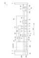
- FIG. 2 is a schematic side view of the deaerator shown in FIG. 1.
- FIG. 3 is a schematic front view of the deaerator shown in FIG. 1.
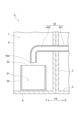
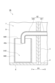
- FIG. 4 is a schematic cross-sectional view taken along the line IV-IV shown in FIG.
- FIG. 5 is a schematic cross-sectional view showing an example of a degassing module installed in the degassing device shown in FIG. 1.
- FIG. FIG. 6 is an enlarged cross-sectional view showing the vicinity of the connector section of the degassing module shown in FIG. 5.
- FIG. FIG. 7 is an enlarged sectional view showing the vicinity of the vibration isolating member of the degassing device shown in FIG.
- FIG. 8 is a schematic cross-sectional view corresponding to FIG. 4 of another example of a deaerator.
- FIG. 9 is a schematic cross-sectional view corresponding to FIG. 4 of another example of a deaerator.
- FIG. 10 is a schematic cross-sectional view corresponding to FIG. 4 of another example of a deaerator.
- FIG. 11 is a schematic cross-sectional view of another example of the degassing device, taken along the line XI-XI shown in FIG.
- FIG. 12 is a schematic cross-sectional view corresponding to FIG. 4 of another example of a deaerator.
- FIG. 13 is a schematic cross-sectional view corresponding to FIG. 4 of another example of a deaerator.
- FIG. 14 is a schematic side view showing another example of a deaerator.
- FIG. 15 is an enlarged sectional view showing the vicinity of the vibration isolating member of the degassing device shown in FIG. 14.
- FIG. 16 is a schematic side view showing another example of a deaerator.
- FIG. 1 is a schematic plan view showing a deaerator according to an embodiment.
- FIG. 2 is a schematic side view of the deaerator shown in FIG. 1.
- FIG. 3 is a schematic front view of the deaerator shown in FIG. 1.
- FIG. 4 is a schematic cross-sectional view taken along the line IV-IV shown in FIG.
- the degassing device 1 shown in FIGS. 1 to 4 is, for example, a degassing device for liquid chromatography, and performs a degassing process on a fluid to be inspected by liquid chromatography.
- the deaerator 1 may be used in gas chromatography, biochemical analysis equipment, inkjet filling equipment, and the like.
- the deaerator 1 includes a housing 5 having a bottom plate 2, a front plate 3, and a rear plate 4, a front panel 6, deaerator modules 10, 20, 30, and vacuum piping 40. , a discharge device 50 , an atmosphere release pipe 60 , an atmosphere release valve 70 , a regulating valve 75 , a control section 80 , and a container 90 .
- the bottom plate 2 of the housing 5 defines the bottom of the deaerator 1.
- the front plate 3 of the housing 5 stands up from the bottom plate 2 and defines the front part of the deaerator 1.
- the rear plate 4 of the housing 5 is erected from the bottom plate 2 so as to face the front plate 3 at the rear of the front plate 3, and defines the rear part of the deaerator 1.
- the front-back direction FR the direction in which the front plate 3 and the rear plate 4 face each other
- the front-rear direction FR the direction on the front plate 3 side with respect to the rear plate 4 (the direction opposite to the rear plate 4 of the front plate 3) is referred to as the front-rear direction FR.
- the housing 5 includes a discharge device 50, an atmosphere release pipe 60, an atmosphere release valve 70, a regulating valve 75, and a control unit above the bottom plate 2 and between the front plate 3 and the rear plate 4 (rear R of the front plate 3). Equipped with 80.
- the front panel 6 is attached to the front plate 3 and forms the front surface of the deaerator 1.
- the front panel 6 includes a front panel body 8 that forms a housing space 7 open to the front F, and a front panel cover (not shown) that is detachably attached to the front panel body 8 and closes the housing space 7. .
- the degassing modules 10, 20, and 30 have the configuration shown in FIG. 5, for example.
- FIG. 5 is a schematic cross-sectional view showing an example of a degassing module installed in the degassing device shown in FIG. 1.
- FIG. FIG. 6 is an enlarged cross-sectional view showing the vicinity of the connector section of the degassing module shown in FIG. 5.
- FIG. 5 shows the configuration of the degassing module 10 as an example, the other degassing modules 20 and 30 have similar configurations.
- the degassing module 10 includes a tube unit 12 in which a plurality of tubes 11 defining a fluid circulation space S1 are tied together at both ends, and a housing 13 that accommodates the tube unit 12.
- a lid part 14 that hermetically seals the opening 13a of the housing 13, a connector part 15 and a connector part 16 that connect and fix the tube unit 12 passing through the lid part 14, and a discharge nozzle part 17 and an opening nozzle that protrude from the housing 13.
- the discharge nozzle portion 17 is formed with a discharge port 17a that communicates with the reduced pressure space S2
- the open nozzle portion 18 is formed with an open port 18a that communicates with the reduced pressure space S2.
- the degassing module 10 has a tube unit 12 that is a gas permeable membrane having gas permeability, and the inside of the housing 13 is connected to a fluid circulation space S1, which is an internal space of each tube 11 of the tube unit 12, and an outside of the tube unit 12. It is partitioned into a depressurized space S2, which is a space of .
- the fluid circulation space S1 is a region to which liquid is supplied, and supplies the liquid introduced from the inlet 12a of the tube unit 12 to the outlet 12b.
- the decompression space S2 is a region into which internal gas is taken in.
- the liquid is supplied to the fluid circulation space S1, which is the internal space of each of the plurality of tubes 11, and air is sucked from the decompression space S2 outside the plurality of tubes 11, so that the tube unit
- the liquid supplied to 12 is degassed.
- Each tube 11 constituting the tube unit 12 is a tube-shaped membrane (gas permeable membrane) that permeates gas but not liquid (see FIG. 6).
- the material, membrane shape, membrane form, etc. of the tube 11 are not particularly limited.
- Examples of the material for the tube 11 include polytetrafluoroethylene (PTFE), tetrafluoroethylene-perfluoroalkyl vinyl ether copolymer (PFA), tetrafluoroethylene-hexafluoropropylene copolymer (FEP), and tetrafluoroethylene-perfluoropropylene copolymer (FEP).
- Fluororesins such as ethylene copolymer (ETFE), polychlorotrifluoroethylene (PCTFE), amorphous fluoropolymer (AF), polyvinylidene fluoride (PVDF), polypropylene (PP) ), polymethylpentene (PMP), silicone, polyimide, and polyamide.
- ethylene copolymer EFT
- PCTFE polychlorotrifluoroethylene
- AF amorphous fluoropolymer
- PVDF polyvinylidene fluoride
- PP polypropylene
- PMP polymethylpentene
- silicone polyimide
- polyamide polyamide
- deaerator 1 In the deaerator 1, three such deaeration modules 10, 20, and 30 are arranged, but one deaeration module may be arranged, or two deaeration modules may be arranged. Alternatively, four or more degassing modules may be arranged.
- the vacuum piping 40 is a member for discharging the gas in each decompression space S2 to the outside.
- the vacuum piping 40 includes a suction pipe section 41 and a discharge pipe section 42.
- the suction pipe section 41 is connected to the degassing modules 10, 20, and 30, and communicates with each decompression space S2 of the degassing modules 10, 20, and 30.
- the suction pipe section 41 includes discharge piping sections 43 to 45 connected to each discharge nozzle section 17 of the deaeration modules 10, 20, and 30, a discharge collection section 46 that collects the discharge piping sections 43 to 45, and a discharge collection section 46. It has a piping section 47 that connects to the discharge device 50 and a detection piping section 48 that connects the discharge collection section 46 to the detector 85.
- the detector 85 is an atmospheric pressure sensor that detects the degree of pressure reduction in each of the reduced pressure spaces S2 of the degassing modules 10, 20, and 30, and is provided in the control unit 80, as will be described later.
- the discharge pipe section 42 is connected to the discharge device 50 and has an outlet 42a open to the outside in order to discharge the gas sent out from the discharge device 50 to the outside of the deaerator 1.
- the end of the discharge pipe section 42 opposite to the discharge device 50 passes through the front plate 3 and extends to the front F of the front plate 3.
- the discharge pipe section 42 has an inner discharge pipe section 421 located at the rear R of the front plate 3 and an outer discharge pipe section 422 located at the front F of the front plate 3.
- a distal end of the inner discharge pipe section 421 on the opposite side from the outer discharge pipe section 422 is connected to the discharge device 50 .
- the outer discharge pipe section 422 is accommodated in the accommodation space 7 of the front panel 6.
- An outlet 42a is formed at the opposite end of the outer discharge pipe section 422 from the inner discharge pipe section 421, and the outer discharge pipe section 422 is bent so that the outlet 42a faces downward.
- At least a portion of the suction pipe section 41 (discharge piping sections 43 to 45, discharge collection section 46, piping section 47, and detection piping section 48) and the discharge pipe section 42 constituting the vacuum piping 40 are made of resin-based tubes, for example. It is configured. All or substantially all the constituent members of the vacuum piping 40 (excluding, for example, the connecting portions) may be made of resin tubes. That is, the vacuum piping 40 may be configured by connecting a plurality of tubes using a connecting member or the like.
- Such a tube is resistant to the solvent used in liquid chromatography, for example, its rubber hardness is preferably within the range of 70 ⁇ 30 degrees, and its oxygen permeability is 6000 cc (STP) cm/cm 2 / It is composed of piping with a sec/cmHg ⁇ 10 ⁇ 10 or less.
- the rubber hardness is preferably within the range of 70 ⁇ 30 degrees, but it is necessary to have appropriate flexibility to prevent loosening or detachment at the connecting portion, and appropriate durability to prevent tube deformation, collapse, and blockage. From the viewpoint of achieving both, the lower limit is more preferably 50 degrees or more, further preferably 55 degrees or more, particularly preferably 60 degrees or more, and the upper limit is 95 degrees or less.
- the angle is more preferably 80 degrees or less, and particularly preferably 75 degrees or less.
- rubber hardness represents Shore A, and can be measured with a durometer (type A), for example, in accordance with JIS K7312 (1996).
- the oxygen permeability is preferably 6000 cc (STP) cm/cm 2 /sec/cmHg ⁇ 10 ⁇ 10 or less, and more preferably 3000 cc (STP) cm/cm 2 / sec/cmHg x 10 -10 or less, more preferably 1000cc (STP) cm/cm 2 /sec/cmHg x 10 -10 or less, particularly preferably 500cc (STP) cm/cm 2 /sec/cmHg x 10 -10 or less and preferably 0.1 cc (STP) cm/cm 2 /sec/cmHg x 10 -10 or more, more preferably 10 cc (STP) cm/cm 2 /sec/cmHg x 10 -10
- the material of the tube constituting the vacuum piping 40 is not particularly limited as long as it has the above-mentioned properties, but examples include vinyl chloride, silicone rubber, and polyamide (nylon) such as nylon 6, nylon 66, nylon 11, and nylon 12. ; Polyurethane; Polyethylene such as low density polyethylene and linear low density polyethylene, polyolefin such as polypropylene; Fluororesin such as FEP, PFA, ETFE, PTFE; Polyester thermoplastic elastomer, styrene thermoplastic elastomer, olefin thermoplastic Examples include thermoplastic elastomers such as elastomers, and one or more of these can be used.
- a resin composition containing a polyolefin and a thermoplastic elastomer is more preferable, and a resin composition containing a polyolefin and a styrene thermoplastic elastomer is more preferable. These are listed as preferred.
- the vacuum piping 40 is made of a resin composition containing the above-mentioned polyolefin and thermoplastic elastomer, it not only has excellent solvent resistance but also has low gas permeability.
- the vacuum piping 40 is made of a resin composition containing the above-mentioned polyolefin and thermoplastic elastomer, so it has appropriate flexibility, and is used at the connection part of the discharge collection part 46 during degassing operation. It has excellent durability because it prevents the tube from loosening or coming off, and also suppresses deformation, collapse, and blockage of the tube.
- the degassing device 1 includes a plurality of degassing modules, including connecting portions between the vacuum piping 40 and the degassing modules 10, 20, and 30, and connecting portions with other parts of the discharge collecting portion 46.
- the degassing device has many connection configurations, by being constructed from a tube with such flexibility and durability, the long-term reliability of the deaerator can be improved.
- the styrenic thermoplastic elastomer used in the vacuum piping 40 is a copolymer having at least one styrene block (hard segment) and at least one elastomer block.
- the elastomer block vinyl-polydiene, polyisoprene, polybutadiene, polyethylene, polychloroprene or poly2,3-dimethylbutadiene can preferably be used.
- a hydrogenated elastomer block can also be used. It is preferable that the elastomer block is hydrogenated because it tends to have better solvent resistance (solvent resistance) and chemical resistance.
- styrene thermoplastic elastomers include styrene-vinyl isoprene-styrene triblock copolymer (SIS), styrene-isobutylene diblock copolymer (SIB), and styrene-butadiene-styrene triblock copolymer (SBS).
- SIS styrene-vinyl isoprene-styrene triblock copolymer
- SIB styrene-isobutylene diblock copolymer
- SBS styrene-butadiene-styrene triblock copolymer
- Styrenic thermoplastic elastomers may be used alone or in combination of two or more.
- a styrene-vinyl isoprene-styrene triblock copolymer because it has better solvent resistance and chemical resistance.
- Suitable examples of such styrene-vinyl isoprene-styrene triblock copolymers include "FG1901 G Polymer” and “FG1924 G Polymer” manufactured by Clayton Co., Ltd., and Hybrer 5127 manufactured by Kuraray Co., Ltd..
- HYBRAR 7311 manufactured by Kuraray Co., Ltd. which is obtained by hydrogenating a vinyl isoprene block, can also be suitably used.
- the lower limit of the content of styrene blocks in the styrene thermoplastic elastomer is preferably 1% by mass, more preferably 5% by mass, based on the total of styrene blocks and elastomer blocks.
- the content is more preferably 10% by mass, and within this range, better solvent resistance (solvent resistance) and chemical resistance tend to be obtained.
- the upper limit is preferably 30% by mass, more preferably 20% by mass, based on the total of the styrene block and elastomer block, and within this range, the solvent resistance (solvent resistance) and chemical resistance performance are improved. It tends to be better.
- the lower limit of the content of the styrene thermoplastic elastomer in the resin composition containing the polyolefin and the styrene thermoplastic elastomer is preferably 3% by mass based on the total of the polyolefin and the styrene thermoplastic elastomer,
- the content is more preferably 5% by mass, and even more preferably 10% by mass, and good solvent resistance (solvent resistance) and chemical resistance tend to be obtained within this range.
- the upper limit thereof is preferably 30% by mass, more preferably 25% by mass, and even more preferably 20% by mass, based on the total of the polyolefin and the styrene thermoplastic elastomer. It tends to provide good solvent resistance and chemical resistance.
- the connecting portions that connect the tubes to each other may be made of hard plastic (polypropylene) or the like.
- the discharge device 50 is connected to the suction pipe section 41 and the discharge pipe section 42 of the vacuum piping 40, and is configured to send gas from the suction pipe section 41 to the discharge pipe section 42.
- the discharge device 50 is connected to each decompression space S2 of the deaeration modules 10, 20, and 30 via the suction pipe section 41, and discharges the gas in each decompression space S2 based on control instructions from the control section 80. It is discharged to the outside from the outlet 42a of the discharge pipe section 42.
- the discharge device 50 includes, for example, a pump 51, a fixing plate 52 to which the pump 51 is fixed, and the like.
- the pump 51 is fixed to the upper surface 52a (the surface opposite to the bottom plate 2) of the fixed plate 52.
- the pump 51 includes a motor 53 for discharging the gas in each decompression space S2 to the outside, and an intake port 54 to which the piping part 47 of the suction pipe part 41 is connected to suck the gas in each decompression space S2.
- an exhaust port 55 is provided to which the discharge pipe section 42 is connected.
- the pump 51 sends out the gas in each decompression space S2 from the piping part 47 to the discharge pipe part 42 by rotating the motor 53 based on a control instruction from the control part 80, and sends out the gas in each decompression space S2 to the outlet of the discharge pipe part 42. It is discharged to the outside from 42a.
- a diaphragm pump such as a diaphragm dry vacuum pump is used.
- a diaphragm pump is a vacuum pump that moves a diaphragm up and down by rotating a motor, and moves gas from an intake port to an exhaust port by the up and down movement of the diaphragm.
- the fixing plate 52 for example, a rectangular metal plate or the like is used.
- the ejection device 50 is supported by the bottom plate 2 of the housing 5 via four vibration isolating members 101. Since the four vibration isolating members 101 have the same configuration, they will be collectively described as the vibration isolating member 101 unless specifically explained separately.
- the vibration isolating member 101 is a member for damping vibrations and suppressing vibrations from being transmitted.
- the vibration isolating member 101 is interposed between the bottom plate 2 and the discharge device 50 (fixed plate 52), and supports the discharge device 50 with respect to the bottom plate 2.
- the four vibration isolation members 101 are arranged at the four corners of the fixed plate 52 in plan view, and support the discharge device 50 (fixed plate 52) at the four corners of the fixed plate 52.
- the ejecting device 50 is arranged at a predetermined height from the upper surface 2a of the bottom plate 2 (the surface on the ejecting device 50 side) by the vibration isolating member 101.
- the vibration isolating member 101 has a configuration shown in FIG. 7, for example.
- FIG. 7 is an enlarged sectional view showing the vicinity of the vibration isolating member of the degassing device shown in FIG. 1 in an enlarged manner.
- the vibration isolation member 101 is interposed between the bottom plate 2 and the fixed plate 52, and supports the fixed plate 52 with respect to the bottom plate 2.
- the vibration isolating member 101 includes a neck portion 101a inserted into the through hole 52c of the fixing plate 52, an upper enlarged diameter portion 101b extending from the neck portion 101a toward the upper surface 52a of the fixing plate 52, and an enlarged diameter portion 101b extending from the neck portion 101a to the fixing plate.
- the upper enlarged diameter part 101b and the lower enlarged diameter part 101c have a diameter larger than that of the through hole 52c of the fixed plate 52 so as not to pass through the through hole 52c of the fixed plate 52. Then, the screw 102 is inserted into the through hole 101d of the vibration isolating member 101 from the upper surface 52a side of the fixed plate 52, and screwed into the screw hole 2c of the bottom plate 2.
- the upper expanded diameter portion 101b and the lower expanded diameter portion 101c sandwich the fixing plate 52 from the upper surface 52a side and the lower surface 52b side, and the lower expanded diameter portion 101c is pressed against the bottom plate 2, and the discharge device 50 is supported by the bottom plate 2 via the vibration isolating member 101.
- the lower enlarged diameter portion 101c serves as a spacer between the fixed plate 52 and the bottom plate 2, so that the fixed plate 52 is disposed at a predetermined height from the bottom plate 2.
- the atmospheric release pipe 60 is a member that communicates with each reduced pressure space S2 of the deaeration modules 10, 20, and 30, and connects each reduced pressure space S2 to the atmospheric release valve 70.
- the atmosphere release piping 60 includes open piping sections 61, 62, 63 connected to the respective opening ports 18a of the deaeration modules 10, 20, 30, an open collection section 64 that collects the open piping sections 61, 62, 63, and an open collection section 64. It has a pipe 65 that connects the section 64 to the atmosphere release valve 70. An end 66 of the open gathering portion 64 of the air-opening pipe 60 on the opposite side to the pipe 65 is closed.
- the atmosphere open pipe 60 is made of the same material as the vacuum pipe 40, for example, a resin tube. More specifically, at least a portion of the open piping sections 61, 62, 63, the open collection section 64, and the piping 65 that constitute the atmosphere open piping 60 are made of, for example, resin-based tubes as described above. All or substantially all (excluding the connecting portions) of the atmosphere-opening piping 60 may be made of resin-based tubes. That is, the atmosphere open piping 60 may be configured by connecting a plurality of resin tubes using a connecting member or the like.
- Such a resin tube is resistant to the solvent used in liquid chromatography, has a rubber hardness in the range of 70 ⁇ 30 degrees, and has an oxygen permeability of 6000cc (STP) cm/cm 2 /sec/cmHg ⁇ 10 -10 or less.
- the connecting portion of the open collecting portion 64 may be made of hard plastic (for example, polypropylene) or the like, similar to the connecting portion of the discharge collecting portion 46.
- the atmosphere release valve 70 is communicated with one end of the atmosphere release pipe 60, and based on the control instruction from the control unit 80, the atmosphere release valve 70 releases the atmosphere at once into each depressurized space S2 of the degassing module 10, 20, 30 via the atmosphere release pipe 60.
- It is a solenoid valve that can be introduced.
- the atmosphere release valve 70 opens the solenoid valve from the closed state (CLOSE) within 5 seconds based on a control instruction from the control unit 80. state (OPEN), and each decompression space S2 (for example, a 1 L container) is opened to the atmosphere within 1 minute.
- the regulating valve 75 is a solenoid valve that is disposed between the deaeration modules 10, 20, 30 and the discharge device 50, and is used to adjust the degree of pressure reduction in the pressure reduction space S2.
- the regulating valve 75 opens the valve when the discharge device 50 is performing pressure reduction processing in the reduced pressure space S2, and on the other hand, when the degree of pressure reduction in the reduced pressure space S2 falls within a predetermined range, the control valve 75 opens the valve.
- the valve is closed based on the control instruction.
- the ejection device 50 can stop its ejection operation.
- the valve is opened based on a control instruction from the control unit 80.
- Both the atmosphere release valve 70 and the adjustment valve 75 are raised to a predetermined height from the bottom plate 2 of the housing 5 by a plurality of legs 71 and a plurality of legs 76.
- the control unit 80 controls the operation and stopping of the pump 51 of the discharge device 50. Further, the control unit 80 includes a detector 85 that detects the degree of pressure reduction in the pressure reduction space S2, and controls the operation of the discharge device 50 and the regulating valve 75 based on the detected degree of pressure reduction. In this control, the exhaust device 50 discharges the atmosphere so that the degree of pressure reduction detected by the detector 85 becomes a predetermined value, and when the degree of pressure reduction in the reduced pressure space S2 falls within a predetermined range, The regulating valve 75 is closed and the operation of the discharge device 50 is stopped. If the degree of pressure reduction detected by the detector 85 falls outside the predetermined range after closing the regulating valve 75, the control unit 80 moves the discharge device 50 again to perform the discharge process.
- the control unit 80 controls the operation of the exhaust device 50 and the atmosphere release valve 70 based on a stop instruction from the outside.
- the atmosphere release valve 70 is opened to open each depressurized space S2 to the atmosphere at once.
- the gas discharge operation by the discharge device 50 may be continued for a predetermined period of time (for example, several seconds), and the atmosphere release valve 70 may be opened to open each decompression space S2 to the atmosphere at once. good.
- the container 90 is a container for storing liquid, and is stored in the storage space 7 of the front panel 6 located at the front F of the front plate 3.
- the container 90 receives and stores the liquid leaked from the tube unit 12 into the reduced pressure space S2 and discharged from the outlet 42a of the discharge pipe section 42.
- the container 90 has a liquid storage space 91 that can contain liquid, and an opening 92 that opens the liquid storage space 91 to the outside.
- the opening 92 is located above the liquid storage space 91 and opens the liquid storage space 91 upward.
- the container 90 is positioned in the accommodation space 7 such that the opening 92 is located below the outlet 42a of the discharge pipe section 42.
- a recess or a projection for positioning the container 90 may be formed in the front panel main body 8 of the front panel 6.
- the outer discharge pipe section 422 and at least a part of the container 90 have translucency that allows the inside to be seen from the outside.
- the container 90 has translucency that allows the inside to be viewed from the outside.
- having translucency means, for example, that the transmittance of visible light, more specifically, light with a wavelength of 400 to 700 nm is preferably 60% or more, more preferably 75% or more. means.
- "not having light transmittance” means, for example, that the transmittance of visible light, more specifically, light with a wavelength of 400 to 700 nm is not included in these ranges. Therefore, the transmittance of the transparent portion (container 90 in this embodiment) for visible light, more specifically, light with a wavelength of 400 to 700 nm, is, for example, 60% or more, 75% or more, or It is over 90%.
- the transmittance of the transparent portion for visible light is preferably 99, for example. % or less, more preferably 95% or less.
- the transmittance of the transparent part for visible light is, for example, 60 nm. % or more and 99% or less, 75% or more and 99% or less, or 75% or more and 95% or less.
- the suction pipe portion 41 communicating with each decompression space S2 of the degassing modules 10, 20, and 30 and the outlet 42a open to the outside are formed in the degassing device 50. Since the discharge pipe section 42 is connected to the discharge pipe section 42, when liquid leaks from the tube unit 12 into the reduced pressure space S2 due to deterioration of the tube unit 12, etc., the liquid leaked into the reduced pressure space S2 is sucked out by the operation of the discharge device 50. It passes through the pipe section 41, the discharge device 50, and the discharge pipe section 42, and is discharged from the outlet 42a of the discharge pipe section 42.
- this deaerator 1 includes a container 90 having a liquid storage space 91 for accommodating the liquid discharged from the outlet 42a of the discharge pipe section 42, the liquid discharged from the outlet 42a of the discharge pipe section 42 is stored. , and can be accommodated in the liquid storage space 91 of the container 90. Therefore, when liquid leaks from the tube unit 12 into the reduced pressure space S2, devices such as the discharge device 50 mounted on the deaerator 1 can be prevented from getting wet with this liquid. Moreover, since the outlet 42a of the discharge pipe part 42 is formed in the outer discharge pipe part 422 located at the front F of the front plate 3, the discharge device 50 and the outlet 42a of the discharge pipe part 42 are separated by the front plate. There is. Therefore, even if liquid spills from the container 90 due to the container 90 being knocked down, it is possible to prevent devices such as the discharge device 50 mounted on the deaerator 1 from getting wet with the liquid.
- control section 80 is arranged at the rear R of the front plate 3, so that the control section 80 and the outlet 42a of the discharge pipe section 42 are separated by the front plate 3. Therefore, even if liquid spills from the container 90 due to, for example, the container 90 being knocked down, it is possible to prevent the control unit 80 from getting wet with the liquid.
- the outer discharge pipe section 422 and the container 90 have translucency that allows the inside to be seen from the outside, so that at least a portion of the outer discharge pipe section 422 and the container 90 can be passed through. It becomes possible to visually confirm the presence or absence of liquid.
- the outer discharge pipe part 422 and the container can be connected to the outer discharge pipe part 422 and the container at the front F of the front plate 3 without providing a sensor for detecting liquid in any of the suction pipe part 41, the discharge device 50, the discharge pipe part 42, and the container 90. By visually observing 90, it can be determined whether or not liquid is leaking from the tube unit 12 into the decompression space S2. Note that even in this case, a sensor for detecting liquid may be provided in any one of the suction tube section 41, the discharge device 50, the discharge tube section 42, and the container 90.
- the container 90 since the container 90 has translucency that allows the inside to be viewed from the outside, it is possible to visually check whether there is a liquid through the container 90. As a result, the container 90 can be visually observed at the front F of the front plate 3 without providing a sensor for detecting liquid in any of the suction pipe section 41, the discharge device 50, the discharge pipe section 42, and the container 90. , it can be determined whether or not liquid is leaking from the tube unit 12 into the reduced pressure space S2.
- the opening 92 that opens the liquid storage space 91 of the container 90 upward is disposed below the outlet 42a of the discharge pipe section 42, so that the liquid can be discharged from the outlet 42a of the discharge pipe section 42.
- the liquid can be easily put into the container 90.
- the vacuum piping 40 is made of a resin composition containing polyolefin and a styrene thermoplastic elastomer, so that it has excellent solvent resistance, chemical resistance, and durability. be able to. Furthermore, gas permeability can be lowered, and the vacuum piping 40 can be prevented from coming off.
- the outer discharge pipe portion may be composed of a plurality of members.
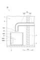
- FIG. 8 is a schematic cross-sectional view corresponding to FIG. 4 of another example of a deaerator.
- an outer discharge pipe section 422A of the discharge pipe section 42A includes a base pipe section 422A1 and a transparent tube section 422A2.
- the base pipe portion 422A1 is integrally formed with the inner discharge pipe portion 421A and continues from the inner discharge pipe portion 421A. Therefore, the base tube portion 422A1 is formed of the same material as the inner discharge tube portion 421A.
- the transparent tube section 422A2 is connected to the base tube section 422A1 and forms the outlet 42a of the discharge tube section 42A. Further, the light-transmitting tube portion 422A2 has a light-transmitting property that allows the inside to be viewed from the outside. In addition, in the deaerator 1A, since the light-transmitting tube portion 422A2 has a light-transmitting property, the container 90 may or may not have a light-transmitting property.
- the connection form between the base tube part 422A1 and the light-transmitting tube part 422A2 includes, for example, a form in which the base tube part 422A1 and the light-transmitting tube part 422A2 are directly connected, a form in which the base tube part 422A1 and the light-transmitting tube part 422A2 are connected through another member, There is a form in which the pipe portion 422A2 is indirectly connected to the pipe portion 422A2.
- the base tube portion 422A1 and the transparent tube portion 422A2 can be directly connected, for example, by press-fitting the base tube portion 422A1 into the transparent tube portion 422A2, or by press-fitting the transparent tube portion 422A2 into the base tube portion 422A1.
- an outer discharge pipe part 422A has a base pipe part 422A1 continuous from an inner discharge pipe part 421A, and is connected to the base pipe part 422A1 to form an outlet 42a, and has a translucent property that allows the inside to be seen from the outside.
- the transparent tube portion 422A2 can be visually checked at the front F of the front plate 3 without providing a sensor for detecting liquid in any of the suction tube portion 41, the discharge device 50, the discharge tube portion 42A, and the container 90. By doing so, it can be determined whether or not liquid is leaking from the tube unit 12 to the reduced pressure space S2. Moreover, since the outer discharge pipe section 422A is configured such that the transparent tube section 422A2 is connected to the base tube section 422A1 which is continuous from the inner discharge pipe section 421A, the discharge pipe section 42A can be easily manufactured.
- the container may have a non-transparent part that does not have light-transmitting properties and a light-transmitting part that has light-transmitting properties.
- FIG. 9 is a schematic cross-sectional view corresponding to FIG. 4 of another example of a deaerator.
- the container 90B has a non-light-transmitting part 90B1 that does not have a light-transmitting property, and a light-transmitting part 90B2 that has a light-transmitting property that allows the interior to be viewed from the outside.
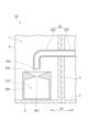
- FIG. 10 is a schematic cross-sectional view of another example of the degassing device, corresponding to FIG. 4.
- the upper part of the liquid storage space 91C of the container 90C is narrowed, and the opening 92C that opens the liquid storage space 91C upward is narrowed.
- the container 90C has a liquid collecting portion 93C that spreads upward from the opening 92C in a funnel shape.
- the opening 92C of the container 90C is narrow, but since the container 90C has a liquid collection part 93C that spreads upward from the opening 92C in a funnel shape, liquid can be collected from a position away from the opening 92C. can be guided to the opening 92C. For this reason, when the opening 92C of the container 90C is narrow, even if the outlet 42a of the discharge pipe section 42 is far from the opening 92C, the liquid discharged from the outlet 42a of the discharge pipe section 42 cannot be properly put into the container 90C. can.
- the upper part of the liquid storage space 91C is narrowed and the opening 92C is narrowed, it is possible to suppress the liquid that has entered the liquid storage space 91C from splashing and scattering to the outside of the liquid storage space 91C. , even if the container 90C is knocked down, it is possible to suppress the liquid from leaking out from the liquid storage space 91C.
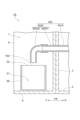
- FIG. 11 is a schematic cross-sectional view of another example of the degassing device, corresponding to the line XI-XI shown in FIG. 2.
- the container 90D extends from below the outlet 42a of the discharge pipe section 42 to below each of the connector sections 15 and 16 of the degassing modules 10, 20, and 30.
- the upper part of the liquid storage space 91D of the container 90D is narrowed, and the opening 92D that opens the liquid storage space 91D upward is narrowed.
- the container 90D has a liquid collecting portion 93D that spreads upward from the opening 92D in a funnel shape.
- the opening 92D is located below the outlet 42a of the discharge pipe section 42, and the liquid collecting section 93D is connected to each connector section 15 of the degassing module 10, 20, 30 and the connector from below the outlet 42a of the discharge pipe section 42. It extends below the section 16.
- the container 90D extends from below the outlet 42a of the discharge pipe section 42 to below each of the connector sections 15 and 16 of the degassing modules 10, 20, and 30. , 20, 30, when liquid leaks into the accommodation space 7 from the connector parts 15 and 16, the liquid leaked into the accommodation space 7 can also be contained in the container 90D. Further, although the opening 92D of the container 90D is narrow, since the container 90D has a liquid collection part 93D that spreads upward from the opening 92D in a funnel shape, the discharge pipe part 42 can be seen even from a position away from the opening 92D.
- the liquid discharged from the outlet 42a and the liquid leaked from the connector parts 15 and 16 of the degassing modules 10, 20, and 30 can be guided to the opening 92D. Therefore, when the opening 92D of the container 90D is narrow, even if the outlet 42a of the discharge pipe section 42 is far from the opening 92D, the liquid discharged from the outlet 42a of the discharge pipe section 42 and the deaeration modules 10, 20, 30 The liquid leaked from each of the connector parts 15 and 16 can be appropriately put into the container 90D. Further, by narrowing the upper part of the liquid storage space 91D and making the opening 92D narrow, it is possible to suppress the liquid that has entered the liquid storage space 91D from splashing and scattering outside the liquid storage space 91D. Even if the container 90D is tipped over, leakage of liquid from the liquid storage space 91D can be suppressed.
- the outer discharge pipe portion may be inserted into the liquid storage space of the container.
- FIG. 12 is a schematic cross-sectional view of another example of the degassing device, corresponding to FIG. 4.
- the outer discharge pipe section 422 is inserted into the liquid storage space 91E from the opening 92E of the container 90E, and the outlet 42a of the discharge pipe section 42 is located below the opening 92E of the container 90E. ing.
- the outer discharge pipe section 422 is inserted into the liquid storage space 91E from the opening 92E of the container 90E, so that the liquid discharged from the outlet 42a of the discharge pipe section 42 can be easily transferred to the container 90E. You can put it in.
- FIG. 13 is a schematic cross-sectional view of another example of the degassing device, corresponding to FIG. 4.
- the container 90F has an opening 92F that opens the liquid storage space 91F upward and an opening 94F that opens the liquid storage space 91F to the outside.
- the opening 94F is formed, for example, in the side wall of the container 90F, and opens the liquid storage space 91F to the side.
- the outer discharge pipe section 422 is inserted into the liquid storage space 91F from the opening 94F of the container 90F, and the outlet 42a of the discharge pipe section 42 is located below the opening 92F of the container 90F. Note that the space between the outer discharge pipe portion 422 and the opening 94F may or may not be sealed.
- the outer discharge pipe section 422 is inserted into the liquid storage space 91F from the opening 94F of the container 90F, so that the liquid discharged from the outlet 42a of the discharge pipe section 42 can be easily transferred to the container 90F. You can put it in. Moreover, since the opening 94F is formed in the side wall of the container 90F, the outer discharge pipe portion 422 can be inserted into the liquid storage space 91F even if the height of the container 90F is high.
- the vibration isolating member may not be attached directly to the housing and the ejection device, but may be attached to the housing and the ejection device via another member.
- FIG. 14 is a schematic side view showing another example of a deaerator.
- FIG. 15 is an enlarged sectional view showing the vicinity of the vibration isolating member of the degassing device shown in FIG. 14.
- the vibration isolating member 103 is formed in a columnar shape such as a cylinder or a square column.
- An upper plate 104 having a threaded groove 104a is connected to the upper end of the vibration isolating member 103, and a threaded groove 105a is connected to the lower end of the other side of the vibration isolating member 103.
- a formed lower plate 105 is connected. Then, the screws 106 inserted into the through holes 52d of the fixing plate 52 are screwed into the thread grooves 104a of the upper plate 104, thereby fixing the upper plate 104 to the fixing plate 52, and are inserted into the through holes 2d of the bottom plate 2.
- the lower plate 105 is fixed to the bottom plate 2 by screwing the screws 107 into the thread grooves 105a of the lower plate 105.
- the vibration isolating member 103 is interposed between the bottom plate 2 of the housing 5 and the fixing plate 52 of the ejection device 50, and supports the ejection device 50 with respect to the bottom plate 2 of the housing 5.
- FIG. 16 is a schematic side view showing another example of a deaerator.
- the evacuation device 56 has the same pump 51 as in the above embodiment, but does not have a configuration corresponding to the fixed plate of the above embodiment.
- the vibration isolating member 109 is attached to the pump 51 and the bottom plate 2 directly or indirectly.
- the shape of the vibration isolating member 109 and the mounting structure of the vibration isolating member 109 to the pump 51 and the bottom plate 2 are, for example, the shape of the vibration isolating member 101 shown in FIG.
- the structure, the shape of the vibration isolating member 103 shown in FIG. 15, the mounting structure of the vibration isolating member 103 to the fixed plate 52 and the bottom plate 2, etc. can be the same.
- the present invention can be used as a degassing device for liquid chromatography, gas chromatography, biochemical analysis equipment, inkjet filling equipment, etc.
- Vibration isolation member 104... Upper plate, 104a... Thread groove, 105... Lower plate, 105a... Thread groove, 106... Screw, 107... Screw, 109... Vibration isolation member, 421, 421A... Inner discharge pipe section, 422, 422A ...outer discharge pipe section, 422A1...base pipe section, 422A2...transparent tube section, FR...front and back direction, F...front, R...backward, S1...fluid circulation space, S2...decompression space.
Landscapes
- Chemical & Material Sciences (AREA)
- Chemical Kinetics & Catalysis (AREA)
- Engineering & Computer Science (AREA)
- Water Supply & Treatment (AREA)
- Degasification And Air Bubble Elimination (AREA)
- Treatment Of Steel In Its Molten State (AREA)
Abstract
L'invention concerne un dispositif de dégazage qui est pourvu : d'un module de dégazage comprenant une unité de tube perméable aux gaz qui sépare un espace de circulation de fluide et un espace dépressurisé ; d'un tube à vide qui comprend une section de tube d'aspiration, qui est reliée au module de dégazage et communique avec l'espace dépressurisé du module de dégazage, et une section de tube d'évacuation, dans laquelle une sortie ouverte vers l'extérieur est formée ; d'un dispositif d'évacuation qui est relié à la section de tube d'aspiration et à la section de tube d'évacuation, et est conçu de façon à envoyer du gaz hors de la section de tube d'aspiration à la section de tube d'évacuation ; d'un boîtier qui comprend une plaque inférieure et une plaque avant érigée sur l'emplacement inférieur, et dans lequel le dispositif d'évacuation est monté au-dessus de la plaque inférieure et derrière la plaque avant ; et d'un récipient comprenant un espace de stockage de liquide pour stocker le liquide évacué de la sortie de la section de tube d'évacuation. La section de tube d'évacuation comprend une section de tube d'évacuation intérieure qui est située derrière la plaque avant et reliée à la section de tube d'évacuation, et une section de tube d'évacuation extérieure qui est située devant la plaque avant et où la sortie est formée.
Applications Claiming Priority (2)
| Application Number | Priority Date | Filing Date | Title |
|---|---|---|---|
| JP2022-102628 | 2022-06-27 | ||
| JP2022102628 | 2022-06-27 |
Publications (1)
| Publication Number | Publication Date |
|---|---|
| WO2024004828A1 true WO2024004828A1 (fr) | 2024-01-04 |
Family
ID=89382906
Family Applications (1)
| Application Number | Title | Priority Date | Filing Date |
|---|---|---|---|
| PCT/JP2023/023203 WO2024004828A1 (fr) | 2022-06-27 | 2023-06-22 | Dispositif de dégazage |
Country Status (1)
| Country | Link |
|---|---|
| WO (1) | WO2024004828A1 (fr) |
Citations (6)
| Publication number | Priority date | Publication date | Assignee | Title |
|---|---|---|---|---|
| JPH06182325A (ja) * | 1992-12-17 | 1994-07-05 | Tohoku Electric Power Co Inc | 液中のアンモニウムイオンの除去方法 |
| JPH0942179A (ja) * | 1995-07-28 | 1997-02-10 | Wet Master Kk | 真空ポンプの冷却装置及びこの冷却装置を備えた真空ポンプを用いた膜脱気式配管防食装置 |
| JP2003010604A (ja) * | 2001-07-02 | 2003-01-14 | Mitsubishi Rayon Co Ltd | 脱気装置 |
| JP2007291896A (ja) * | 2006-04-24 | 2007-11-08 | Erc:Kk | 真空系における減圧吸引システム |
| WO2008035714A1 (fr) * | 2006-09-22 | 2008-03-27 | Nitto Denko Corporation | Dispositif de dégazage |
| JP2011088026A (ja) * | 2009-10-20 | 2011-05-06 | Shimadzu Corp | 脱気装置 |
-
2023
- 2023-06-22 WO PCT/JP2023/023203 patent/WO2024004828A1/fr unknown
Patent Citations (6)
| Publication number | Priority date | Publication date | Assignee | Title |
|---|---|---|---|---|
| JPH06182325A (ja) * | 1992-12-17 | 1994-07-05 | Tohoku Electric Power Co Inc | 液中のアンモニウムイオンの除去方法 |
| JPH0942179A (ja) * | 1995-07-28 | 1997-02-10 | Wet Master Kk | 真空ポンプの冷却装置及びこの冷却装置を備えた真空ポンプを用いた膜脱気式配管防食装置 |
| JP2003010604A (ja) * | 2001-07-02 | 2003-01-14 | Mitsubishi Rayon Co Ltd | 脱気装置 |
| JP2007291896A (ja) * | 2006-04-24 | 2007-11-08 | Erc:Kk | 真空系における減圧吸引システム |
| WO2008035714A1 (fr) * | 2006-09-22 | 2008-03-27 | Nitto Denko Corporation | Dispositif de dégazage |
| JP2011088026A (ja) * | 2009-10-20 | 2011-05-06 | Shimadzu Corp | 脱気装置 |
Similar Documents
| Publication | Publication Date | Title |
|---|---|---|
| US20080103429A1 (en) | Pumping material for cassette based dialysis and pumping mechanism using same | |
| JPH11510404A (ja) | 静脈輸注ライン流制御システムのためのカセット | |
| WO2011112835A2 (fr) | Appareil à tube de mise à l'air libre et procédé | |
| JP5016584B2 (ja) | 密閉燃料タンク装置 | |
| JP2004183663A (ja) | 負圧作動式閉鎖バルブ並びに燃料蒸気の排出制御装置および制御方法 | |
| WO2024004828A1 (fr) | Dispositif de dégazage | |
| JP2004257264A (ja) | 満タン制御弁構造 | |
| WO2020095721A1 (fr) | Machine d'aspiration médicale | |
| WO2024004829A1 (fr) | Désaérateur | |
| JP4371957B2 (ja) | 消毒剤又は洗浄剤導入装置、及びその使用方法 | |
| WO2024004827A1 (fr) | Dispositif de dégazage | |
| JP7416286B2 (ja) | 脱気装置 | |
| WO2024004830A1 (fr) | Dégazeur | |
| JPH09303218A (ja) | 燃料蒸気処理装置 | |
| WO2010082417A1 (fr) | Cartouche de purification d'eau et purificateur d'eau | |
| JP6194203B2 (ja) | 液状廃棄物処理装置 | |
| JPH09112372A (ja) | 燃料タンクのブリーザ装置 | |
| JP2005171947A (ja) | キャニスタ | |
| JP2005054704A (ja) | 蒸発燃料処理装置 | |
| JP2009082602A (ja) | 収容容器 | |
| JP2000170609A (ja) | 燃料貯留装置の故障診断装置 | |
| JP2008303729A (ja) | 蒸発燃料処理装置 | |
| JP3452103B2 (ja) | 蒸発燃料処理装置 | |
| JP2001317417A (ja) | インタンクキャニスタシステムのリーク診断装置 | |
| CN217707137U (zh) | 试剂储存装置 |
Legal Events
| Date | Code | Title | Description |
|---|---|---|---|
| 121 | Ep: the epo has been informed by wipo that ep was designated in this application |
Ref document number: 23831272 Country of ref document: EP Kind code of ref document: A1 |