WO2024004828A1 - Degassing device - Google Patents
Degassing device Download PDFInfo
- Publication number
- WO2024004828A1 WO2024004828A1 PCT/JP2023/023203 JP2023023203W WO2024004828A1 WO 2024004828 A1 WO2024004828 A1 WO 2024004828A1 JP 2023023203 W JP2023023203 W JP 2023023203W WO 2024004828 A1 WO2024004828 A1 WO 2024004828A1
- Authority
- WO
- WIPO (PCT)
- Prior art keywords
- discharge pipe
- pipe section
- container
- liquid
- deaerator
- Prior art date
Links
- 238000007872 degassing Methods 0.000 title claims abstract description 66
- 239000007788 liquid Substances 0.000 claims abstract description 144
- 239000012530 fluid Substances 0.000 claims abstract description 9
- 238000005192 partition Methods 0.000 claims abstract description 3
- PPBRXRYQALVLMV-UHFFFAOYSA-N Styrene Chemical compound C=CC1=CC=CC=C1 PPBRXRYQALVLMV-UHFFFAOYSA-N 0.000 claims description 34
- 230000006837 decompression Effects 0.000 claims description 18
- 229920002725 thermoplastic elastomer Polymers 0.000 claims description 17
- 229920000098 polyolefin Polymers 0.000 claims description 10
- 239000011342 resin composition Substances 0.000 claims description 9
- 230000004913 activation Effects 0.000 claims description 2
- 230000009849 deactivation Effects 0.000 claims description 2
- 239000007789 gas Substances 0.000 description 20
- 239000002904 solvent Substances 0.000 description 15
- 230000009467 reduction Effects 0.000 description 13
- 229920001971 elastomer Polymers 0.000 description 11
- 230000035699 permeability Effects 0.000 description 8
- -1 polytetrafluoroethylene Polymers 0.000 description 8
- 239000000126 substance Substances 0.000 description 8
- 239000000806 elastomer Substances 0.000 description 7
- 239000000463 material Substances 0.000 description 7
- 230000001105 regulatory effect Effects 0.000 description 7
- 239000011347 resin Substances 0.000 description 7
- 229920005989 resin Polymers 0.000 description 7
- 229920000428 triblock copolymer Polymers 0.000 description 7
- 230000006866 deterioration Effects 0.000 description 6
- 238000004811 liquid chromatography Methods 0.000 description 6
- 238000002834 transmittance Methods 0.000 description 6
- 239000004743 Polypropylene Substances 0.000 description 5
- QVGXLLKOCUKJST-UHFFFAOYSA-N atomic oxygen Chemical compound [O] QVGXLLKOCUKJST-UHFFFAOYSA-N 0.000 description 5
- 239000012528 membrane Substances 0.000 description 5
- 239000001301 oxygen Substances 0.000 description 5
- 229910052760 oxygen Inorganic materials 0.000 description 5
- 229920001155 polypropylene Polymers 0.000 description 5
- 230000004308 accommodation Effects 0.000 description 4
- 229920001577 copolymer Polymers 0.000 description 4
- 238000002955 isolation Methods 0.000 description 4
- 239000005060 rubber Substances 0.000 description 4
- CKMMENIHLWUQNF-UHFFFAOYSA-N C=CC1=CC=CC=C1.C(=C)C=CC(C)=C.C=CC1=CC=CC=C1 Chemical compound C=CC1=CC=CC=C1.C(=C)C=CC(C)=C.C=CC1=CC=CC=C1 CKMMENIHLWUQNF-UHFFFAOYSA-N 0.000 description 3
- 238000001514 detection method Methods 0.000 description 3
- BXOUVIIITJXIKB-UHFFFAOYSA-N ethene;styrene Chemical group C=C.C=CC1=CC=CC=C1 BXOUVIIITJXIKB-UHFFFAOYSA-N 0.000 description 3
- 238000000034 method Methods 0.000 description 3
- 229920009441 perflouroethylene propylene Polymers 0.000 description 3
- 229920001343 polytetrafluoroethylene Polymers 0.000 description 3
- 239000004810 polytetrafluoroethylene Substances 0.000 description 3
- 239000002033 PVDF binder Substances 0.000 description 2
- 239000004952 Polyamide Substances 0.000 description 2
- 239000004698 Polyethylene Substances 0.000 description 2
- 229920006465 Styrenic thermoplastic elastomer Polymers 0.000 description 2
- 238000012742 biochemical analysis Methods 0.000 description 2
- 238000007599 discharging Methods 0.000 description 2
- 229920000840 ethylene tetrafluoroethylene copolymer Polymers 0.000 description 2
- 229920002313 fluoropolymer Polymers 0.000 description 2
- 239000004811 fluoropolymer Substances 0.000 description 2
- 238000004817 gas chromatography Methods 0.000 description 2
- 229920011301 perfluoro alkoxyl alkane Polymers 0.000 description 2
- 229920003023 plastic Polymers 0.000 description 2
- 239000004033 plastic Substances 0.000 description 2
- 229920002493 poly(chlorotrifluoroethylene) Polymers 0.000 description 2
- 229920002647 polyamide Polymers 0.000 description 2
- 239000005023 polychlorotrifluoroethylene (PCTFE) polymer Substances 0.000 description 2
- 229920000573 polyethylene Polymers 0.000 description 2
- 229920000642 polymer Polymers 0.000 description 2
- 229920006124 polyolefin elastomer Polymers 0.000 description 2
- 229920005995 polystyrene-polyisobutylene Polymers 0.000 description 2
- 229920002981 polyvinylidene fluoride Polymers 0.000 description 2
- 229920000468 styrene butadiene styrene block copolymer Polymers 0.000 description 2
- RLRINNKRRPQIGW-UHFFFAOYSA-N 1-ethenyl-2-[4-(2-ethenylphenyl)butyl]benzene Chemical compound C=CC1=CC=CC=C1CCCCC1=CC=CC=C1C=C RLRINNKRRPQIGW-UHFFFAOYSA-N 0.000 description 1
- PPWGXYXJMQAWSX-UHFFFAOYSA-N 2-methylhexa-1,3,5-triene Chemical compound CC(=C)C=CC=C PPWGXYXJMQAWSX-UHFFFAOYSA-N 0.000 description 1
- VGGSQFUCUMXWEO-UHFFFAOYSA-N Ethene Chemical compound C=C VGGSQFUCUMXWEO-UHFFFAOYSA-N 0.000 description 1
- 239000005977 Ethylene Substances 0.000 description 1
- JHWNWJKBPDFINM-UHFFFAOYSA-N Laurolactam Chemical compound O=C1CCCCCCCCCCCN1 JHWNWJKBPDFINM-UHFFFAOYSA-N 0.000 description 1
- 239000004677 Nylon Substances 0.000 description 1
- 229920000571 Nylon 11 Polymers 0.000 description 1
- 229920000299 Nylon 12 Polymers 0.000 description 1
- 229920002292 Nylon 6 Polymers 0.000 description 1
- 229920002302 Nylon 6,6 Polymers 0.000 description 1
- 239000005062 Polybutadiene Substances 0.000 description 1
- 239000004642 Polyimide Substances 0.000 description 1
- 239000002174 Styrene-butadiene Substances 0.000 description 1
- 239000004809 Teflon Substances 0.000 description 1
- 229920006362 Teflon® Polymers 0.000 description 1
- BZHJMEDXRYGGRV-UHFFFAOYSA-N Vinyl chloride Chemical compound ClC=C BZHJMEDXRYGGRV-UHFFFAOYSA-N 0.000 description 1
- 150000001336 alkenes Chemical class 0.000 description 1
- XRERONKQLIQWGW-UHFFFAOYSA-N but-1-ene;styrene Chemical compound CCC=C.C=CC1=CC=CC=C1 XRERONKQLIQWGW-UHFFFAOYSA-N 0.000 description 1
- MTAZNLWOLGHBHU-UHFFFAOYSA-N butadiene-styrene rubber Chemical compound C=CC=C.C=CC1=CC=CC=C1 MTAZNLWOLGHBHU-UHFFFAOYSA-N 0.000 description 1
- 239000000470 constituent Substances 0.000 description 1
- 238000013016 damping Methods 0.000 description 1
- 229920001038 ethylene copolymer Polymers 0.000 description 1
- 229920000092 linear low density polyethylene Polymers 0.000 description 1
- 239000004707 linear low-density polyethylene Substances 0.000 description 1
- 230000007774 longterm Effects 0.000 description 1
- 229920001684 low density polyethylene Polymers 0.000 description 1
- 239000004702 low-density polyethylene Substances 0.000 description 1
- 230000007257 malfunction Effects 0.000 description 1
- 238000004519 manufacturing process Methods 0.000 description 1
- 239000002184 metal Substances 0.000 description 1
- 229920001778 nylon Polymers 0.000 description 1
- JRZJOMJEPLMPRA-UHFFFAOYSA-N olefin Natural products CCCCCCCC=C JRZJOMJEPLMPRA-UHFFFAOYSA-N 0.000 description 1
- 239000012466 permeate Substances 0.000 description 1
- 229920001084 poly(chloroprene) Polymers 0.000 description 1
- 229920002857 polybutadiene Polymers 0.000 description 1
- 229920000728 polyester Polymers 0.000 description 1
- 229920001721 polyimide Polymers 0.000 description 1
- 229920001195 polyisoprene Polymers 0.000 description 1
- 239000011116 polymethylpentene Substances 0.000 description 1
- 229920001296 polysiloxane Polymers 0.000 description 1
- 229920002635 polyurethane Polymers 0.000 description 1
- 239000004814 polyurethane Substances 0.000 description 1
- 230000008569 process Effects 0.000 description 1
- 229920002379 silicone rubber Polymers 0.000 description 1
- 239000004945 silicone rubber Substances 0.000 description 1
- 125000006850 spacer group Chemical group 0.000 description 1
- 239000011115 styrene butadiene Substances 0.000 description 1
- 229920003048 styrene butadiene rubber Polymers 0.000 description 1
- 229920001169 thermoplastic Polymers 0.000 description 1
- 239000004416 thermosoftening plastic Substances 0.000 description 1
Images


Classifications
-
- B—PERFORMING OPERATIONS; TRANSPORTING
- B01—PHYSICAL OR CHEMICAL PROCESSES OR APPARATUS IN GENERAL
- B01D—SEPARATION
- B01D19/00—Degasification of liquids
-
- B—PERFORMING OPERATIONS; TRANSPORTING
- B01—PHYSICAL OR CHEMICAL PROCESSES OR APPARATUS IN GENERAL
- B01D—SEPARATION
- B01D61/00—Processes of separation using semi-permeable membranes, e.g. dialysis, osmosis or ultrafiltration; Apparatus, accessories or auxiliary operations specially adapted therefor
-
- B—PERFORMING OPERATIONS; TRANSPORTING
- B01—PHYSICAL OR CHEMICAL PROCESSES OR APPARATUS IN GENERAL
- B01D—SEPARATION
- B01D63/00—Apparatus in general for separation processes using semi-permeable membranes
- B01D63/06—Tubular membrane modules
Definitions
- the present invention relates to a deaerator.
- Patent Document 1 discloses a degassing device used in liquid chromatography devices and the like.
- a depressurized space in a deaeration module in which a tube unit is provided and a discharge device (pump) are communicated by vacuum piping, and the tube unit is removed by operating the discharge device. It is configured to degas the flowing liquid.
- the liquid leaked into the reduced pressure space is discharged from the ejection device into the degassing device through the vacuum piping due to the operation of the evacuation device.
- equipment such as a discharge device mounted on the deaerator may become wet and malfunction.
- one aspect of the present invention aims to provide a deaerator that can suppress equipment installed in the deaerator from getting wet when liquid leaks from a tube unit into a decompressed space. .
- a deaeration device includes a deaeration module having a gas permeable tube unit that partitions between a fluid circulation space and a decompression space, and a deaeration module connected to the deaeration module.
- vacuum piping having a suction pipe section communicating with the reduced pressure space of the vacuum pipe section, and a discharge pipe section having an outlet opened to the outside; a housing having a bottom plate and a front plate erected on the bottom plate, the housing having the discharge device mounted above the bottom plate and behind the front plate; and an outlet of the discharge pipe part.
- a container having a liquid storage space for accommodating liquid discharged from the front plate; an outer discharge pipe portion located at the front and having an outlet formed therein.
- the suction pipe section that communicates with the depressurized space of the degassing module and the discharge pipe section that has an outlet open to the outside are connected to the evacuation device, so that deterioration of the tube unit may occur.
- the liquid leaked into the reduced pressure space is discharged from the outlet of the discharge pipe through the suction pipe section, the discharge device, and the discharge pipe section due to the operation of the discharge device.
- this deaerator includes a container having a liquid storage space for storing the liquid discharged from the outlet of the discharge pipe, the liquid discharged from the outlet of the discharge pipe is transferred to the liquid storage space of the container. It can be placed and accommodated.
- the degassing device may further include a control unit that controls activation and deactivation of the exhaust device, and the housing may include the control unit above the bottom plate and behind the front plate. good.
- the control section is disposed behind the front plate, so that the control section and the outlet of the discharge pipe section are separated by the front plate. For this reason, even if liquid spills from the container by, for example, tipping the container over, it is possible to prevent the control unit from getting wet with the liquid.
- the deaerator according to [1] or [2] at least a portion of the outer discharge pipe portion and the container may have translucency that allows the inside to be viewed from the outside.
- providing a sensor increases the cost and complicates the configuration of the degassing device. Furthermore, if the sensor fails, liquid cannot be detected.
- the outer discharge pipe section and at least a part of the container have translucency that allows the inside to be seen from the outside, so that the presence or absence of liquid can be visually confirmed through the outer discharge pipe section and at least a part of the container. becomes possible.
- This makes it possible to visually check the outer discharge pipe and container in front of the front plate without having to install a sensor to detect liquid in any of the suction pipe, discharge device, discharge pipe, or container. It can be determined whether liquid is leaking from the unit into the vacuum space.
- a sensor for detecting liquid may be provided in any one of the suction pipe section, the discharge device, the discharge pipe section, and the container.
- the container may have translucency that allows the inside to be viewed from the outside.
- the container since the container has translucency that allows the inside to be seen from the outside, it is possible to visually check the presence or absence of liquid through the container.
- the container can be visually inspected in front of the front plate and the tube unit can be accessed from the decompressed space. It can be determined whether liquid is leaking or not.
- the outer discharge pipe section includes a base pipe section that is continuous from the inner discharge pipe section and is connected to the base pipe section to form an outlet. It may also include a light-transmitting tube portion having a light-transmitting property that allows the inside to be viewed from the outside.
- an outer discharge pipe part is connected to a base pipe part that is continuous from an inner discharge pipe part, and a transparent pipe part that is connected to the base pipe part to form an outlet and has a translucent property that allows the inside to be seen from the outside.
- the tube unit can be easily inspected by visually observing the transparent tube section in front of the front plate. It can be determined whether or not liquid is leaking into the decompressed space. Furthermore, since the outer discharge pipe section is configured such that the transparent tube section is connected to the base tube section that is continuous from the inner discharge pipe section, the discharge pipe section can be easily manufactured.
- the container has an opening that opens the liquid storage space upward, and the opening of the container is located at the outlet of the discharge pipe section. It may be placed below.
- the opening that opens the liquid storage space of the container upward is arranged below the outlet of the discharge pipe section, so that the liquid discharged from the outlet of the discharge pipe section can be easily put into the container. Can be done.
- the container may have a liquid collecting portion that expands upward from the opening in a funnel shape.
- the container since the container has a liquid collection portion that spreads upward from the opening in a funnel shape, the liquid can be guided to the opening from a position away from the opening. Therefore, even if the opening of the container is narrow or the outlet of the discharge pipe section is far from the opening, the liquid discharged from the outlet of the discharge pipe section can be appropriately placed into the container.
- the container has an opening that opens the liquid storage space to the outside, and the outer discharge pipe section opens the liquid storage space from the opening. It may be inserted into.
- the outer discharge pipe section is inserted into the liquid storage space from the opening of the container, so that the liquid discharged from the outlet of the discharge pipe section can be easily put into the container.
- At least a portion of the vacuum piping may be made of a resin composition containing a polyolefin and a styrene thermoplastic elastomer.
- at least a portion of the vacuum piping is made of a resin composition containing a polyolefin and a styrene thermoplastic elastomer, so that it can have excellent solvent resistance, chemical resistance, and durability.
- gas permeability can be lowered, and the vacuum piping can be prevented from coming off.
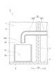
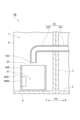
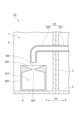
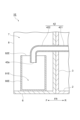
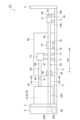
- FIG. 1 is a schematic plan view showing a deaerator according to an embodiment of the present invention.
- FIG. 2 is a schematic side view of the deaerator shown in FIG. 1.
- FIG. 3 is a schematic front view of the deaerator shown in FIG. 1.
- FIG. 4 is a schematic cross-sectional view taken along the line IV-IV shown in FIG.
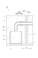
- FIG. 5 is a schematic cross-sectional view showing an example of a degassing module installed in the degassing device shown in FIG. 1.
- FIG. FIG. 6 is an enlarged cross-sectional view showing the vicinity of the connector section of the degassing module shown in FIG. 5.
- FIG. FIG. 7 is an enlarged sectional view showing the vicinity of the vibration isolating member of the degassing device shown in FIG.
- FIG. 8 is a schematic cross-sectional view corresponding to FIG. 4 of another example of a deaerator.
- FIG. 9 is a schematic cross-sectional view corresponding to FIG. 4 of another example of a deaerator.
- FIG. 10 is a schematic cross-sectional view corresponding to FIG. 4 of another example of a deaerator.
- FIG. 11 is a schematic cross-sectional view of another example of the degassing device, taken along the line XI-XI shown in FIG.
- FIG. 12 is a schematic cross-sectional view corresponding to FIG. 4 of another example of a deaerator.
- FIG. 13 is a schematic cross-sectional view corresponding to FIG. 4 of another example of a deaerator.
- FIG. 14 is a schematic side view showing another example of a deaerator.
- FIG. 15 is an enlarged sectional view showing the vicinity of the vibration isolating member of the degassing device shown in FIG. 14.
- FIG. 16 is a schematic side view showing another example of a deaerator.
- FIG. 1 is a schematic plan view showing a deaerator according to an embodiment.
- FIG. 2 is a schematic side view of the deaerator shown in FIG. 1.
- FIG. 3 is a schematic front view of the deaerator shown in FIG. 1.
- FIG. 4 is a schematic cross-sectional view taken along the line IV-IV shown in FIG.
- the degassing device 1 shown in FIGS. 1 to 4 is, for example, a degassing device for liquid chromatography, and performs a degassing process on a fluid to be inspected by liquid chromatography.
- the deaerator 1 may be used in gas chromatography, biochemical analysis equipment, inkjet filling equipment, and the like.
- the deaerator 1 includes a housing 5 having a bottom plate 2, a front plate 3, and a rear plate 4, a front panel 6, deaerator modules 10, 20, 30, and vacuum piping 40. , a discharge device 50 , an atmosphere release pipe 60 , an atmosphere release valve 70 , a regulating valve 75 , a control section 80 , and a container 90 .
- the bottom plate 2 of the housing 5 defines the bottom of the deaerator 1.
- the front plate 3 of the housing 5 stands up from the bottom plate 2 and defines the front part of the deaerator 1.
- the rear plate 4 of the housing 5 is erected from the bottom plate 2 so as to face the front plate 3 at the rear of the front plate 3, and defines the rear part of the deaerator 1.
- the front-back direction FR the direction in which the front plate 3 and the rear plate 4 face each other
- the front-rear direction FR the direction on the front plate 3 side with respect to the rear plate 4 (the direction opposite to the rear plate 4 of the front plate 3) is referred to as the front-rear direction FR.
- the housing 5 includes a discharge device 50, an atmosphere release pipe 60, an atmosphere release valve 70, a regulating valve 75, and a control unit above the bottom plate 2 and between the front plate 3 and the rear plate 4 (rear R of the front plate 3). Equipped with 80.
- the front panel 6 is attached to the front plate 3 and forms the front surface of the deaerator 1.
- the front panel 6 includes a front panel body 8 that forms a housing space 7 open to the front F, and a front panel cover (not shown) that is detachably attached to the front panel body 8 and closes the housing space 7. .
- the degassing modules 10, 20, and 30 have the configuration shown in FIG. 5, for example.
- FIG. 5 is a schematic cross-sectional view showing an example of a degassing module installed in the degassing device shown in FIG. 1.
- FIG. FIG. 6 is an enlarged cross-sectional view showing the vicinity of the connector section of the degassing module shown in FIG. 5.
- FIG. 5 shows the configuration of the degassing module 10 as an example, the other degassing modules 20 and 30 have similar configurations.
- the degassing module 10 includes a tube unit 12 in which a plurality of tubes 11 defining a fluid circulation space S1 are tied together at both ends, and a housing 13 that accommodates the tube unit 12.
- a lid part 14 that hermetically seals the opening 13a of the housing 13, a connector part 15 and a connector part 16 that connect and fix the tube unit 12 passing through the lid part 14, and a discharge nozzle part 17 and an opening nozzle that protrude from the housing 13.
- the discharge nozzle portion 17 is formed with a discharge port 17a that communicates with the reduced pressure space S2
- the open nozzle portion 18 is formed with an open port 18a that communicates with the reduced pressure space S2.
- the degassing module 10 has a tube unit 12 that is a gas permeable membrane having gas permeability, and the inside of the housing 13 is connected to a fluid circulation space S1, which is an internal space of each tube 11 of the tube unit 12, and an outside of the tube unit 12. It is partitioned into a depressurized space S2, which is a space of .
- the fluid circulation space S1 is a region to which liquid is supplied, and supplies the liquid introduced from the inlet 12a of the tube unit 12 to the outlet 12b.
- the decompression space S2 is a region into which internal gas is taken in.
- the liquid is supplied to the fluid circulation space S1, which is the internal space of each of the plurality of tubes 11, and air is sucked from the decompression space S2 outside the plurality of tubes 11, so that the tube unit
- the liquid supplied to 12 is degassed.
- Each tube 11 constituting the tube unit 12 is a tube-shaped membrane (gas permeable membrane) that permeates gas but not liquid (see FIG. 6).
- the material, membrane shape, membrane form, etc. of the tube 11 are not particularly limited.
- Examples of the material for the tube 11 include polytetrafluoroethylene (PTFE), tetrafluoroethylene-perfluoroalkyl vinyl ether copolymer (PFA), tetrafluoroethylene-hexafluoropropylene copolymer (FEP), and tetrafluoroethylene-perfluoropropylene copolymer (FEP).
- Fluororesins such as ethylene copolymer (ETFE), polychlorotrifluoroethylene (PCTFE), amorphous fluoropolymer (AF), polyvinylidene fluoride (PVDF), polypropylene (PP) ), polymethylpentene (PMP), silicone, polyimide, and polyamide.
- ethylene copolymer EFT
- PCTFE polychlorotrifluoroethylene
- AF amorphous fluoropolymer
- PVDF polyvinylidene fluoride
- PP polypropylene
- PMP polymethylpentene
- silicone polyimide
- polyamide polyamide
- deaerator 1 In the deaerator 1, three such deaeration modules 10, 20, and 30 are arranged, but one deaeration module may be arranged, or two deaeration modules may be arranged. Alternatively, four or more degassing modules may be arranged.
- the vacuum piping 40 is a member for discharging the gas in each decompression space S2 to the outside.
- the vacuum piping 40 includes a suction pipe section 41 and a discharge pipe section 42.
- the suction pipe section 41 is connected to the degassing modules 10, 20, and 30, and communicates with each decompression space S2 of the degassing modules 10, 20, and 30.
- the suction pipe section 41 includes discharge piping sections 43 to 45 connected to each discharge nozzle section 17 of the deaeration modules 10, 20, and 30, a discharge collection section 46 that collects the discharge piping sections 43 to 45, and a discharge collection section 46. It has a piping section 47 that connects to the discharge device 50 and a detection piping section 48 that connects the discharge collection section 46 to the detector 85.
- the detector 85 is an atmospheric pressure sensor that detects the degree of pressure reduction in each of the reduced pressure spaces S2 of the degassing modules 10, 20, and 30, and is provided in the control unit 80, as will be described later.
- the discharge pipe section 42 is connected to the discharge device 50 and has an outlet 42a open to the outside in order to discharge the gas sent out from the discharge device 50 to the outside of the deaerator 1.
- the end of the discharge pipe section 42 opposite to the discharge device 50 passes through the front plate 3 and extends to the front F of the front plate 3.
- the discharge pipe section 42 has an inner discharge pipe section 421 located at the rear R of the front plate 3 and an outer discharge pipe section 422 located at the front F of the front plate 3.
- a distal end of the inner discharge pipe section 421 on the opposite side from the outer discharge pipe section 422 is connected to the discharge device 50 .
- the outer discharge pipe section 422 is accommodated in the accommodation space 7 of the front panel 6.
- An outlet 42a is formed at the opposite end of the outer discharge pipe section 422 from the inner discharge pipe section 421, and the outer discharge pipe section 422 is bent so that the outlet 42a faces downward.
- At least a portion of the suction pipe section 41 (discharge piping sections 43 to 45, discharge collection section 46, piping section 47, and detection piping section 48) and the discharge pipe section 42 constituting the vacuum piping 40 are made of resin-based tubes, for example. It is configured. All or substantially all the constituent members of the vacuum piping 40 (excluding, for example, the connecting portions) may be made of resin tubes. That is, the vacuum piping 40 may be configured by connecting a plurality of tubes using a connecting member or the like.
- Such a tube is resistant to the solvent used in liquid chromatography, for example, its rubber hardness is preferably within the range of 70 ⁇ 30 degrees, and its oxygen permeability is 6000 cc (STP) cm/cm 2 / It is composed of piping with a sec/cmHg ⁇ 10 ⁇ 10 or less.
- the rubber hardness is preferably within the range of 70 ⁇ 30 degrees, but it is necessary to have appropriate flexibility to prevent loosening or detachment at the connecting portion, and appropriate durability to prevent tube deformation, collapse, and blockage. From the viewpoint of achieving both, the lower limit is more preferably 50 degrees or more, further preferably 55 degrees or more, particularly preferably 60 degrees or more, and the upper limit is 95 degrees or less.
- the angle is more preferably 80 degrees or less, and particularly preferably 75 degrees or less.
- rubber hardness represents Shore A, and can be measured with a durometer (type A), for example, in accordance with JIS K7312 (1996).
- the oxygen permeability is preferably 6000 cc (STP) cm/cm 2 /sec/cmHg ⁇ 10 ⁇ 10 or less, and more preferably 3000 cc (STP) cm/cm 2 / sec/cmHg x 10 -10 or less, more preferably 1000cc (STP) cm/cm 2 /sec/cmHg x 10 -10 or less, particularly preferably 500cc (STP) cm/cm 2 /sec/cmHg x 10 -10 or less and preferably 0.1 cc (STP) cm/cm 2 /sec/cmHg x 10 -10 or more, more preferably 10 cc (STP) cm/cm 2 /sec/cmHg x 10 -10
- the material of the tube constituting the vacuum piping 40 is not particularly limited as long as it has the above-mentioned properties, but examples include vinyl chloride, silicone rubber, and polyamide (nylon) such as nylon 6, nylon 66, nylon 11, and nylon 12. ; Polyurethane; Polyethylene such as low density polyethylene and linear low density polyethylene, polyolefin such as polypropylene; Fluororesin such as FEP, PFA, ETFE, PTFE; Polyester thermoplastic elastomer, styrene thermoplastic elastomer, olefin thermoplastic Examples include thermoplastic elastomers such as elastomers, and one or more of these can be used.
- a resin composition containing a polyolefin and a thermoplastic elastomer is more preferable, and a resin composition containing a polyolefin and a styrene thermoplastic elastomer is more preferable. These are listed as preferred.
- the vacuum piping 40 is made of a resin composition containing the above-mentioned polyolefin and thermoplastic elastomer, it not only has excellent solvent resistance but also has low gas permeability.
- the vacuum piping 40 is made of a resin composition containing the above-mentioned polyolefin and thermoplastic elastomer, so it has appropriate flexibility, and is used at the connection part of the discharge collection part 46 during degassing operation. It has excellent durability because it prevents the tube from loosening or coming off, and also suppresses deformation, collapse, and blockage of the tube.
- the degassing device 1 includes a plurality of degassing modules, including connecting portions between the vacuum piping 40 and the degassing modules 10, 20, and 30, and connecting portions with other parts of the discharge collecting portion 46.
- the degassing device has many connection configurations, by being constructed from a tube with such flexibility and durability, the long-term reliability of the deaerator can be improved.
- the styrenic thermoplastic elastomer used in the vacuum piping 40 is a copolymer having at least one styrene block (hard segment) and at least one elastomer block.
- the elastomer block vinyl-polydiene, polyisoprene, polybutadiene, polyethylene, polychloroprene or poly2,3-dimethylbutadiene can preferably be used.
- a hydrogenated elastomer block can also be used. It is preferable that the elastomer block is hydrogenated because it tends to have better solvent resistance (solvent resistance) and chemical resistance.
- styrene thermoplastic elastomers include styrene-vinyl isoprene-styrene triblock copolymer (SIS), styrene-isobutylene diblock copolymer (SIB), and styrene-butadiene-styrene triblock copolymer (SBS).
- SIS styrene-vinyl isoprene-styrene triblock copolymer
- SIB styrene-isobutylene diblock copolymer
- SBS styrene-butadiene-styrene triblock copolymer
- Styrenic thermoplastic elastomers may be used alone or in combination of two or more.
- a styrene-vinyl isoprene-styrene triblock copolymer because it has better solvent resistance and chemical resistance.
- Suitable examples of such styrene-vinyl isoprene-styrene triblock copolymers include "FG1901 G Polymer” and “FG1924 G Polymer” manufactured by Clayton Co., Ltd., and Hybrer 5127 manufactured by Kuraray Co., Ltd..
- HYBRAR 7311 manufactured by Kuraray Co., Ltd. which is obtained by hydrogenating a vinyl isoprene block, can also be suitably used.
- the lower limit of the content of styrene blocks in the styrene thermoplastic elastomer is preferably 1% by mass, more preferably 5% by mass, based on the total of styrene blocks and elastomer blocks.
- the content is more preferably 10% by mass, and within this range, better solvent resistance (solvent resistance) and chemical resistance tend to be obtained.
- the upper limit is preferably 30% by mass, more preferably 20% by mass, based on the total of the styrene block and elastomer block, and within this range, the solvent resistance (solvent resistance) and chemical resistance performance are improved. It tends to be better.
- the lower limit of the content of the styrene thermoplastic elastomer in the resin composition containing the polyolefin and the styrene thermoplastic elastomer is preferably 3% by mass based on the total of the polyolefin and the styrene thermoplastic elastomer,
- the content is more preferably 5% by mass, and even more preferably 10% by mass, and good solvent resistance (solvent resistance) and chemical resistance tend to be obtained within this range.
- the upper limit thereof is preferably 30% by mass, more preferably 25% by mass, and even more preferably 20% by mass, based on the total of the polyolefin and the styrene thermoplastic elastomer. It tends to provide good solvent resistance and chemical resistance.
- the connecting portions that connect the tubes to each other may be made of hard plastic (polypropylene) or the like.
- the discharge device 50 is connected to the suction pipe section 41 and the discharge pipe section 42 of the vacuum piping 40, and is configured to send gas from the suction pipe section 41 to the discharge pipe section 42.
- the discharge device 50 is connected to each decompression space S2 of the deaeration modules 10, 20, and 30 via the suction pipe section 41, and discharges the gas in each decompression space S2 based on control instructions from the control section 80. It is discharged to the outside from the outlet 42a of the discharge pipe section 42.
- the discharge device 50 includes, for example, a pump 51, a fixing plate 52 to which the pump 51 is fixed, and the like.
- the pump 51 is fixed to the upper surface 52a (the surface opposite to the bottom plate 2) of the fixed plate 52.
- the pump 51 includes a motor 53 for discharging the gas in each decompression space S2 to the outside, and an intake port 54 to which the piping part 47 of the suction pipe part 41 is connected to suck the gas in each decompression space S2.
- an exhaust port 55 is provided to which the discharge pipe section 42 is connected.
- the pump 51 sends out the gas in each decompression space S2 from the piping part 47 to the discharge pipe part 42 by rotating the motor 53 based on a control instruction from the control part 80, and sends out the gas in each decompression space S2 to the outlet of the discharge pipe part 42. It is discharged to the outside from 42a.
- a diaphragm pump such as a diaphragm dry vacuum pump is used.
- a diaphragm pump is a vacuum pump that moves a diaphragm up and down by rotating a motor, and moves gas from an intake port to an exhaust port by the up and down movement of the diaphragm.
- the fixing plate 52 for example, a rectangular metal plate or the like is used.
- the ejection device 50 is supported by the bottom plate 2 of the housing 5 via four vibration isolating members 101. Since the four vibration isolating members 101 have the same configuration, they will be collectively described as the vibration isolating member 101 unless specifically explained separately.
- the vibration isolating member 101 is a member for damping vibrations and suppressing vibrations from being transmitted.
- the vibration isolating member 101 is interposed between the bottom plate 2 and the discharge device 50 (fixed plate 52), and supports the discharge device 50 with respect to the bottom plate 2.
- the four vibration isolation members 101 are arranged at the four corners of the fixed plate 52 in plan view, and support the discharge device 50 (fixed plate 52) at the four corners of the fixed plate 52.
- the ejecting device 50 is arranged at a predetermined height from the upper surface 2a of the bottom plate 2 (the surface on the ejecting device 50 side) by the vibration isolating member 101.
- the vibration isolating member 101 has a configuration shown in FIG. 7, for example.
- FIG. 7 is an enlarged sectional view showing the vicinity of the vibration isolating member of the degassing device shown in FIG. 1 in an enlarged manner.
- the vibration isolation member 101 is interposed between the bottom plate 2 and the fixed plate 52, and supports the fixed plate 52 with respect to the bottom plate 2.
- the vibration isolating member 101 includes a neck portion 101a inserted into the through hole 52c of the fixing plate 52, an upper enlarged diameter portion 101b extending from the neck portion 101a toward the upper surface 52a of the fixing plate 52, and an enlarged diameter portion 101b extending from the neck portion 101a to the fixing plate.
- the upper enlarged diameter part 101b and the lower enlarged diameter part 101c have a diameter larger than that of the through hole 52c of the fixed plate 52 so as not to pass through the through hole 52c of the fixed plate 52. Then, the screw 102 is inserted into the through hole 101d of the vibration isolating member 101 from the upper surface 52a side of the fixed plate 52, and screwed into the screw hole 2c of the bottom plate 2.
- the upper expanded diameter portion 101b and the lower expanded diameter portion 101c sandwich the fixing plate 52 from the upper surface 52a side and the lower surface 52b side, and the lower expanded diameter portion 101c is pressed against the bottom plate 2, and the discharge device 50 is supported by the bottom plate 2 via the vibration isolating member 101.
- the lower enlarged diameter portion 101c serves as a spacer between the fixed plate 52 and the bottom plate 2, so that the fixed plate 52 is disposed at a predetermined height from the bottom plate 2.
- the atmospheric release pipe 60 is a member that communicates with each reduced pressure space S2 of the deaeration modules 10, 20, and 30, and connects each reduced pressure space S2 to the atmospheric release valve 70.
- the atmosphere release piping 60 includes open piping sections 61, 62, 63 connected to the respective opening ports 18a of the deaeration modules 10, 20, 30, an open collection section 64 that collects the open piping sections 61, 62, 63, and an open collection section 64. It has a pipe 65 that connects the section 64 to the atmosphere release valve 70. An end 66 of the open gathering portion 64 of the air-opening pipe 60 on the opposite side to the pipe 65 is closed.
- the atmosphere open pipe 60 is made of the same material as the vacuum pipe 40, for example, a resin tube. More specifically, at least a portion of the open piping sections 61, 62, 63, the open collection section 64, and the piping 65 that constitute the atmosphere open piping 60 are made of, for example, resin-based tubes as described above. All or substantially all (excluding the connecting portions) of the atmosphere-opening piping 60 may be made of resin-based tubes. That is, the atmosphere open piping 60 may be configured by connecting a plurality of resin tubes using a connecting member or the like.
- Such a resin tube is resistant to the solvent used in liquid chromatography, has a rubber hardness in the range of 70 ⁇ 30 degrees, and has an oxygen permeability of 6000cc (STP) cm/cm 2 /sec/cmHg ⁇ 10 -10 or less.
- the connecting portion of the open collecting portion 64 may be made of hard plastic (for example, polypropylene) or the like, similar to the connecting portion of the discharge collecting portion 46.
- the atmosphere release valve 70 is communicated with one end of the atmosphere release pipe 60, and based on the control instruction from the control unit 80, the atmosphere release valve 70 releases the atmosphere at once into each depressurized space S2 of the degassing module 10, 20, 30 via the atmosphere release pipe 60.
- It is a solenoid valve that can be introduced.
- the atmosphere release valve 70 opens the solenoid valve from the closed state (CLOSE) within 5 seconds based on a control instruction from the control unit 80. state (OPEN), and each decompression space S2 (for example, a 1 L container) is opened to the atmosphere within 1 minute.
- the regulating valve 75 is a solenoid valve that is disposed between the deaeration modules 10, 20, 30 and the discharge device 50, and is used to adjust the degree of pressure reduction in the pressure reduction space S2.
- the regulating valve 75 opens the valve when the discharge device 50 is performing pressure reduction processing in the reduced pressure space S2, and on the other hand, when the degree of pressure reduction in the reduced pressure space S2 falls within a predetermined range, the control valve 75 opens the valve.
- the valve is closed based on the control instruction.
- the ejection device 50 can stop its ejection operation.
- the valve is opened based on a control instruction from the control unit 80.
- Both the atmosphere release valve 70 and the adjustment valve 75 are raised to a predetermined height from the bottom plate 2 of the housing 5 by a plurality of legs 71 and a plurality of legs 76.
- the control unit 80 controls the operation and stopping of the pump 51 of the discharge device 50. Further, the control unit 80 includes a detector 85 that detects the degree of pressure reduction in the pressure reduction space S2, and controls the operation of the discharge device 50 and the regulating valve 75 based on the detected degree of pressure reduction. In this control, the exhaust device 50 discharges the atmosphere so that the degree of pressure reduction detected by the detector 85 becomes a predetermined value, and when the degree of pressure reduction in the reduced pressure space S2 falls within a predetermined range, The regulating valve 75 is closed and the operation of the discharge device 50 is stopped. If the degree of pressure reduction detected by the detector 85 falls outside the predetermined range after closing the regulating valve 75, the control unit 80 moves the discharge device 50 again to perform the discharge process.
- the control unit 80 controls the operation of the exhaust device 50 and the atmosphere release valve 70 based on a stop instruction from the outside.
- the atmosphere release valve 70 is opened to open each depressurized space S2 to the atmosphere at once.
- the gas discharge operation by the discharge device 50 may be continued for a predetermined period of time (for example, several seconds), and the atmosphere release valve 70 may be opened to open each decompression space S2 to the atmosphere at once. good.
- the container 90 is a container for storing liquid, and is stored in the storage space 7 of the front panel 6 located at the front F of the front plate 3.
- the container 90 receives and stores the liquid leaked from the tube unit 12 into the reduced pressure space S2 and discharged from the outlet 42a of the discharge pipe section 42.
- the container 90 has a liquid storage space 91 that can contain liquid, and an opening 92 that opens the liquid storage space 91 to the outside.
- the opening 92 is located above the liquid storage space 91 and opens the liquid storage space 91 upward.
- the container 90 is positioned in the accommodation space 7 such that the opening 92 is located below the outlet 42a of the discharge pipe section 42.
- a recess or a projection for positioning the container 90 may be formed in the front panel main body 8 of the front panel 6.
- the outer discharge pipe section 422 and at least a part of the container 90 have translucency that allows the inside to be seen from the outside.
- the container 90 has translucency that allows the inside to be viewed from the outside.
- having translucency means, for example, that the transmittance of visible light, more specifically, light with a wavelength of 400 to 700 nm is preferably 60% or more, more preferably 75% or more. means.
- "not having light transmittance” means, for example, that the transmittance of visible light, more specifically, light with a wavelength of 400 to 700 nm is not included in these ranges. Therefore, the transmittance of the transparent portion (container 90 in this embodiment) for visible light, more specifically, light with a wavelength of 400 to 700 nm, is, for example, 60% or more, 75% or more, or It is over 90%.
- the transmittance of the transparent portion for visible light is preferably 99, for example. % or less, more preferably 95% or less.
- the transmittance of the transparent part for visible light is, for example, 60 nm. % or more and 99% or less, 75% or more and 99% or less, or 75% or more and 95% or less.
- the suction pipe portion 41 communicating with each decompression space S2 of the degassing modules 10, 20, and 30 and the outlet 42a open to the outside are formed in the degassing device 50. Since the discharge pipe section 42 is connected to the discharge pipe section 42, when liquid leaks from the tube unit 12 into the reduced pressure space S2 due to deterioration of the tube unit 12, etc., the liquid leaked into the reduced pressure space S2 is sucked out by the operation of the discharge device 50. It passes through the pipe section 41, the discharge device 50, and the discharge pipe section 42, and is discharged from the outlet 42a of the discharge pipe section 42.
- this deaerator 1 includes a container 90 having a liquid storage space 91 for accommodating the liquid discharged from the outlet 42a of the discharge pipe section 42, the liquid discharged from the outlet 42a of the discharge pipe section 42 is stored. , and can be accommodated in the liquid storage space 91 of the container 90. Therefore, when liquid leaks from the tube unit 12 into the reduced pressure space S2, devices such as the discharge device 50 mounted on the deaerator 1 can be prevented from getting wet with this liquid. Moreover, since the outlet 42a of the discharge pipe part 42 is formed in the outer discharge pipe part 422 located at the front F of the front plate 3, the discharge device 50 and the outlet 42a of the discharge pipe part 42 are separated by the front plate. There is. Therefore, even if liquid spills from the container 90 due to the container 90 being knocked down, it is possible to prevent devices such as the discharge device 50 mounted on the deaerator 1 from getting wet with the liquid.
- control section 80 is arranged at the rear R of the front plate 3, so that the control section 80 and the outlet 42a of the discharge pipe section 42 are separated by the front plate 3. Therefore, even if liquid spills from the container 90 due to, for example, the container 90 being knocked down, it is possible to prevent the control unit 80 from getting wet with the liquid.
- the outer discharge pipe section 422 and the container 90 have translucency that allows the inside to be seen from the outside, so that at least a portion of the outer discharge pipe section 422 and the container 90 can be passed through. It becomes possible to visually confirm the presence or absence of liquid.
- the outer discharge pipe part 422 and the container can be connected to the outer discharge pipe part 422 and the container at the front F of the front plate 3 without providing a sensor for detecting liquid in any of the suction pipe part 41, the discharge device 50, the discharge pipe part 42, and the container 90. By visually observing 90, it can be determined whether or not liquid is leaking from the tube unit 12 into the decompression space S2. Note that even in this case, a sensor for detecting liquid may be provided in any one of the suction tube section 41, the discharge device 50, the discharge tube section 42, and the container 90.
- the container 90 since the container 90 has translucency that allows the inside to be viewed from the outside, it is possible to visually check whether there is a liquid through the container 90. As a result, the container 90 can be visually observed at the front F of the front plate 3 without providing a sensor for detecting liquid in any of the suction pipe section 41, the discharge device 50, the discharge pipe section 42, and the container 90. , it can be determined whether or not liquid is leaking from the tube unit 12 into the reduced pressure space S2.
- the opening 92 that opens the liquid storage space 91 of the container 90 upward is disposed below the outlet 42a of the discharge pipe section 42, so that the liquid can be discharged from the outlet 42a of the discharge pipe section 42.
- the liquid can be easily put into the container 90.
- the vacuum piping 40 is made of a resin composition containing polyolefin and a styrene thermoplastic elastomer, so that it has excellent solvent resistance, chemical resistance, and durability. be able to. Furthermore, gas permeability can be lowered, and the vacuum piping 40 can be prevented from coming off.
- the outer discharge pipe portion may be composed of a plurality of members.
- FIG. 8 is a schematic cross-sectional view corresponding to FIG. 4 of another example of a deaerator.
- an outer discharge pipe section 422A of the discharge pipe section 42A includes a base pipe section 422A1 and a transparent tube section 422A2.
- the base pipe portion 422A1 is integrally formed with the inner discharge pipe portion 421A and continues from the inner discharge pipe portion 421A. Therefore, the base tube portion 422A1 is formed of the same material as the inner discharge tube portion 421A.
- the transparent tube section 422A2 is connected to the base tube section 422A1 and forms the outlet 42a of the discharge tube section 42A. Further, the light-transmitting tube portion 422A2 has a light-transmitting property that allows the inside to be viewed from the outside. In addition, in the deaerator 1A, since the light-transmitting tube portion 422A2 has a light-transmitting property, the container 90 may or may not have a light-transmitting property.
- the connection form between the base tube part 422A1 and the light-transmitting tube part 422A2 includes, for example, a form in which the base tube part 422A1 and the light-transmitting tube part 422A2 are directly connected, a form in which the base tube part 422A1 and the light-transmitting tube part 422A2 are connected through another member, There is a form in which the pipe portion 422A2 is indirectly connected to the pipe portion 422A2.
- the base tube portion 422A1 and the transparent tube portion 422A2 can be directly connected, for example, by press-fitting the base tube portion 422A1 into the transparent tube portion 422A2, or by press-fitting the transparent tube portion 422A2 into the base tube portion 422A1.
- an outer discharge pipe part 422A has a base pipe part 422A1 continuous from an inner discharge pipe part 421A, and is connected to the base pipe part 422A1 to form an outlet 42a, and has a translucent property that allows the inside to be seen from the outside.
- the transparent tube portion 422A2 can be visually checked at the front F of the front plate 3 without providing a sensor for detecting liquid in any of the suction tube portion 41, the discharge device 50, the discharge tube portion 42A, and the container 90. By doing so, it can be determined whether or not liquid is leaking from the tube unit 12 to the reduced pressure space S2. Moreover, since the outer discharge pipe section 422A is configured such that the transparent tube section 422A2 is connected to the base tube section 422A1 which is continuous from the inner discharge pipe section 421A, the discharge pipe section 42A can be easily manufactured.
- the container may have a non-transparent part that does not have light-transmitting properties and a light-transmitting part that has light-transmitting properties.
- FIG. 9 is a schematic cross-sectional view corresponding to FIG. 4 of another example of a deaerator.
- the container 90B has a non-light-transmitting part 90B1 that does not have a light-transmitting property, and a light-transmitting part 90B2 that has a light-transmitting property that allows the interior to be viewed from the outside.
- FIG. 10 is a schematic cross-sectional view of another example of the degassing device, corresponding to FIG. 4.
- the upper part of the liquid storage space 91C of the container 90C is narrowed, and the opening 92C that opens the liquid storage space 91C upward is narrowed.
- the container 90C has a liquid collecting portion 93C that spreads upward from the opening 92C in a funnel shape.
- the opening 92C of the container 90C is narrow, but since the container 90C has a liquid collection part 93C that spreads upward from the opening 92C in a funnel shape, liquid can be collected from a position away from the opening 92C. can be guided to the opening 92C. For this reason, when the opening 92C of the container 90C is narrow, even if the outlet 42a of the discharge pipe section 42 is far from the opening 92C, the liquid discharged from the outlet 42a of the discharge pipe section 42 cannot be properly put into the container 90C. can.
- the upper part of the liquid storage space 91C is narrowed and the opening 92C is narrowed, it is possible to suppress the liquid that has entered the liquid storage space 91C from splashing and scattering to the outside of the liquid storage space 91C. , even if the container 90C is knocked down, it is possible to suppress the liquid from leaking out from the liquid storage space 91C.
- FIG. 11 is a schematic cross-sectional view of another example of the degassing device, corresponding to the line XI-XI shown in FIG. 2.
- the container 90D extends from below the outlet 42a of the discharge pipe section 42 to below each of the connector sections 15 and 16 of the degassing modules 10, 20, and 30.
- the upper part of the liquid storage space 91D of the container 90D is narrowed, and the opening 92D that opens the liquid storage space 91D upward is narrowed.
- the container 90D has a liquid collecting portion 93D that spreads upward from the opening 92D in a funnel shape.
- the opening 92D is located below the outlet 42a of the discharge pipe section 42, and the liquid collecting section 93D is connected to each connector section 15 of the degassing module 10, 20, 30 and the connector from below the outlet 42a of the discharge pipe section 42. It extends below the section 16.
- the container 90D extends from below the outlet 42a of the discharge pipe section 42 to below each of the connector sections 15 and 16 of the degassing modules 10, 20, and 30. , 20, 30, when liquid leaks into the accommodation space 7 from the connector parts 15 and 16, the liquid leaked into the accommodation space 7 can also be contained in the container 90D. Further, although the opening 92D of the container 90D is narrow, since the container 90D has a liquid collection part 93D that spreads upward from the opening 92D in a funnel shape, the discharge pipe part 42 can be seen even from a position away from the opening 92D.
- the liquid discharged from the outlet 42a and the liquid leaked from the connector parts 15 and 16 of the degassing modules 10, 20, and 30 can be guided to the opening 92D. Therefore, when the opening 92D of the container 90D is narrow, even if the outlet 42a of the discharge pipe section 42 is far from the opening 92D, the liquid discharged from the outlet 42a of the discharge pipe section 42 and the deaeration modules 10, 20, 30 The liquid leaked from each of the connector parts 15 and 16 can be appropriately put into the container 90D. Further, by narrowing the upper part of the liquid storage space 91D and making the opening 92D narrow, it is possible to suppress the liquid that has entered the liquid storage space 91D from splashing and scattering outside the liquid storage space 91D. Even if the container 90D is tipped over, leakage of liquid from the liquid storage space 91D can be suppressed.
- the outer discharge pipe portion may be inserted into the liquid storage space of the container.
- FIG. 12 is a schematic cross-sectional view of another example of the degassing device, corresponding to FIG. 4.
- the outer discharge pipe section 422 is inserted into the liquid storage space 91E from the opening 92E of the container 90E, and the outlet 42a of the discharge pipe section 42 is located below the opening 92E of the container 90E. ing.
- the outer discharge pipe section 422 is inserted into the liquid storage space 91E from the opening 92E of the container 90E, so that the liquid discharged from the outlet 42a of the discharge pipe section 42 can be easily transferred to the container 90E. You can put it in.
- FIG. 13 is a schematic cross-sectional view of another example of the degassing device, corresponding to FIG. 4.
- the container 90F has an opening 92F that opens the liquid storage space 91F upward and an opening 94F that opens the liquid storage space 91F to the outside.
- the opening 94F is formed, for example, in the side wall of the container 90F, and opens the liquid storage space 91F to the side.
- the outer discharge pipe section 422 is inserted into the liquid storage space 91F from the opening 94F of the container 90F, and the outlet 42a of the discharge pipe section 42 is located below the opening 92F of the container 90F. Note that the space between the outer discharge pipe portion 422 and the opening 94F may or may not be sealed.
- the outer discharge pipe section 422 is inserted into the liquid storage space 91F from the opening 94F of the container 90F, so that the liquid discharged from the outlet 42a of the discharge pipe section 42 can be easily transferred to the container 90F. You can put it in. Moreover, since the opening 94F is formed in the side wall of the container 90F, the outer discharge pipe portion 422 can be inserted into the liquid storage space 91F even if the height of the container 90F is high.
- the vibration isolating member may not be attached directly to the housing and the ejection device, but may be attached to the housing and the ejection device via another member.
- FIG. 14 is a schematic side view showing another example of a deaerator.
- FIG. 15 is an enlarged sectional view showing the vicinity of the vibration isolating member of the degassing device shown in FIG. 14.
- the vibration isolating member 103 is formed in a columnar shape such as a cylinder or a square column.
- An upper plate 104 having a threaded groove 104a is connected to the upper end of the vibration isolating member 103, and a threaded groove 105a is connected to the lower end of the other side of the vibration isolating member 103.
- a formed lower plate 105 is connected. Then, the screws 106 inserted into the through holes 52d of the fixing plate 52 are screwed into the thread grooves 104a of the upper plate 104, thereby fixing the upper plate 104 to the fixing plate 52, and are inserted into the through holes 2d of the bottom plate 2.
- the lower plate 105 is fixed to the bottom plate 2 by screwing the screws 107 into the thread grooves 105a of the lower plate 105.
- the vibration isolating member 103 is interposed between the bottom plate 2 of the housing 5 and the fixing plate 52 of the ejection device 50, and supports the ejection device 50 with respect to the bottom plate 2 of the housing 5.
- FIG. 16 is a schematic side view showing another example of a deaerator.
- the evacuation device 56 has the same pump 51 as in the above embodiment, but does not have a configuration corresponding to the fixed plate of the above embodiment.
- the vibration isolating member 109 is attached to the pump 51 and the bottom plate 2 directly or indirectly.
- the shape of the vibration isolating member 109 and the mounting structure of the vibration isolating member 109 to the pump 51 and the bottom plate 2 are, for example, the shape of the vibration isolating member 101 shown in FIG.
- the structure, the shape of the vibration isolating member 103 shown in FIG. 15, the mounting structure of the vibration isolating member 103 to the fixed plate 52 and the bottom plate 2, etc. can be the same.
- the present invention can be used as a degassing device for liquid chromatography, gas chromatography, biochemical analysis equipment, inkjet filling equipment, etc.
- Vibration isolation member 104... Upper plate, 104a... Thread groove, 105... Lower plate, 105a... Thread groove, 106... Screw, 107... Screw, 109... Vibration isolation member, 421, 421A... Inner discharge pipe section, 422, 422A ...outer discharge pipe section, 422A1...base pipe section, 422A2...transparent tube section, FR...front and back direction, F...front, R...backward, S1...fluid circulation space, S2...decompression space.
Abstract
This degassing device is provided with: a degassing module comprising a gas-permeable tube unit that partitions between a fluid circulation space and a depressurized space; a vacuum tubing that has a suction tube section, which is connected to the degassing module and communicates with the depressurized space of the degassing module, and a discharge tube section, in which an outlet opened to the exterior is formed; a discharge device that is connected to the suction tube section and the discharge tube section, and is configured so as to send gas out from the suction tube section to the discharge tube section; a housing which has a bottom plate and a front plate erected on the bottom place, and in which the discharge device is mounted above the bottom plate and behind the front plate; and a vessel having a liquid storage space for storing liquid discharged from the outlet of the discharge tube section. The discharge tube section has an inside discharge tube section that is located behind the front plate and connected to the discharge tube section, and an outside discharge tube section which is located in front of the front plate and where the outlet is formed.
Description
本発明は、脱気装置に関する。
The present invention relates to a deaerator.
特許文献1には、液体クロマトグラフィ装置等に用いられる脱気装置が開示されている。
Patent Document 1 discloses a degassing device used in liquid chromatography devices and the like.
特許文献1に記載の脱気装置は、チューブユニットが設けられた脱気モジュール内の減圧空間と排出装置(ポンプ)とが真空配管により連通されており、排出装置を作動させることでチューブユニットを流通する液体を脱気するように構成されている。しかしながら、チューブユニットの劣化等によりチューブユニットから減圧空間に液体が漏出すると、排出装置の作動により、減圧空間に漏出した液体が真空配管を通って排出装置から脱気装置内に排出される。その結果、脱気装置に搭載された排出装置等の機器が濡れて故障する可能性がある。
In the deaeration device described in Patent Document 1, a depressurized space in a deaeration module in which a tube unit is provided and a discharge device (pump) are communicated by vacuum piping, and the tube unit is removed by operating the discharge device. It is configured to degas the flowing liquid. However, when liquid leaks from the tube unit into the reduced pressure space due to deterioration of the tube unit or the like, the liquid leaked into the reduced pressure space is discharged from the ejection device into the degassing device through the vacuum piping due to the operation of the evacuation device. As a result, equipment such as a discharge device mounted on the deaerator may become wet and malfunction.
そこで、本発明の一側面は、チューブユニットから減圧空間に液体が漏出した際に、脱気装置に搭載された機器が濡れるのを抑制することができる脱気装置を提供することを目的とする。
Therefore, one aspect of the present invention aims to provide a deaerator that can suppress equipment installed in the deaerator from getting wet when liquid leaks from a tube unit into a decompressed space. .
[1] 本発明の一側面に係る脱気装置は、流体流通空間と減圧空間との間を仕切るガス透過性を有するチューブユニットを有する脱気モジュールと、脱気モジュールに接続されて脱気モジュールの減圧空間に連通される吸引管部と、外部に開放された出口が形成された排出管部と、を有する真空配管と、吸引管部及び排出管部に接続されて吸引管部から排出管部に気体を送り出すように構成された排出装置と、底板及び底板に立設された前板を有し、底板の上方かつ前板の後方に排出装置を搭載するハウジングと、排出管部の出口から排出された液体を収容するための液体収容空間を有する容器と、を備え、排出管部は、前板の後方に位置して排出管部に接続される内側排出管部と、前板の前方に位置して出口が形成される外側排出管部と、を有する。
[1] A deaeration device according to one aspect of the present invention includes a deaeration module having a gas permeable tube unit that partitions between a fluid circulation space and a decompression space, and a deaeration module connected to the deaeration module. vacuum piping having a suction pipe section communicating with the reduced pressure space of the vacuum pipe section, and a discharge pipe section having an outlet opened to the outside; a housing having a bottom plate and a front plate erected on the bottom plate, the housing having the discharge device mounted above the bottom plate and behind the front plate; and an outlet of the discharge pipe part. a container having a liquid storage space for accommodating liquid discharged from the front plate; an outer discharge pipe portion located at the front and having an outlet formed therein.
この脱気装置では、排出装置に、脱気モジュールの減圧空間に連通される吸引管部と外部に開放された出口が形成された排出管部とが接続されているため、チューブユニットの劣化等によりチューブユニットから減圧空間に液体が漏出すると、排出装置の作動により、減圧空間に漏出した液体は、吸引管部、排出装置、及び排出管部を通って、排出管部の出口から排出される。そして、この脱気装置では、排出管部の出口から排出された液体を収容するための液体収容空間を有する容器を備えるため、排出管部の出口から排出され液体を、容器の液体収容空間に入れて収容することができる。このため、チューブユニットから減圧空間に液体が漏出した際に、脱気装置に搭載された排出装置等の機器がこの液体で濡れるのを抑制することができる。しかも、排出管部の出口が前板の前方に位置する外側排出管部に形成されているため、排出装置と排出管部の出口とが前板により隔てられている。このため、容器を倒す等して容器から液体がこぼれたとしても、脱気装置に搭載された排出装置等の機器がこの液体で濡れるのを抑制することができる。
In this deaerator, the suction pipe section that communicates with the depressurized space of the degassing module and the discharge pipe section that has an outlet open to the outside are connected to the evacuation device, so that deterioration of the tube unit may occur. When liquid leaks from the tube unit into the reduced pressure space, the liquid leaked into the reduced pressure space is discharged from the outlet of the discharge pipe through the suction pipe section, the discharge device, and the discharge pipe section due to the operation of the discharge device. . Since this deaerator includes a container having a liquid storage space for storing the liquid discharged from the outlet of the discharge pipe, the liquid discharged from the outlet of the discharge pipe is transferred to the liquid storage space of the container. It can be placed and accommodated. Therefore, when liquid leaks from the tube unit into the reduced pressure space, equipment such as a discharge device mounted on the deaerator can be prevented from getting wet with this liquid. Moreover, since the outlet of the discharge pipe section is formed in the outer discharge pipe section located in front of the front plate, the discharge device and the outlet of the discharge pipe section are separated by the front plate. For this reason, even if liquid spills from the container by, for example, knocking the container over, equipment such as a discharge device mounted on the deaerator can be prevented from getting wet with the liquid.
[2] [1]に記載の脱気装置において、排出装置の作動及び作動の停止を制御する制御部を更に備え、ハウジングは、底板の上方かつ前板の後方に制御部を搭載してもよい。この脱気装置では、制御部が前板の後方に配置されていることで、制御部と排出管部の出口とが前板により隔てられている。このため、容器を倒す等して容器から液体がこぼれたとしても、制御部がこの液体で濡れるのを抑制することができる。
[2] The degassing device according to [1] may further include a control unit that controls activation and deactivation of the exhaust device, and the housing may include the control unit above the bottom plate and behind the front plate. good. In this deaerator, the control section is disposed behind the front plate, so that the control section and the outlet of the discharge pipe section are separated by the front plate. For this reason, even if liquid spills from the container by, for example, tipping the container over, it is possible to prevent the control unit from getting wet with the liquid.
[3] [1]又は[2]に記載の脱気装置において、外側排出管部及び容器の少なくとも一部は、外部から内部を視認可能な透光性を有してもよい。チューブユニットの劣化等によりチューブユニットから減圧空間に液体が漏出すると、早急に排出装置の駆動を停止することが好ましい。このため、チューブユニットから減圧空間に漏出した液体の通り道である、吸引管部、排出装置、排出管部、及び容器の何れかに、液体を検出するセンサを設けることが考えられる。しかしながら、センサを設けるとコストが高くなるとともに、脱気装置の構成が複雑になる。また、センサが故障すると、液体を検出することができない。この脱気装置では、外側排出管部及び容器の少なくとも一部が外部から内部を視認可能な透光性を有することで、外側排出管部及び容器の少なくとも一部を通して液体の有無を視認することが可能となる。これにより、吸引管部、排出装置、排出管部、及び容器の何れかに、液体を検出するセンサを設けなくても、前板の前方において外側排出管部及び容器を目視することで、チューブユニットから減圧空間に液体が漏出しているか否かを判断することができる。なお、この場合であっても、吸引管部、排出装置、排出管部、及び容器の何れかに、液体を検出するセンサを設けてもよい。
[3] In the deaerator according to [1] or [2], at least a portion of the outer discharge pipe portion and the container may have translucency that allows the inside to be viewed from the outside. When liquid leaks from the tube unit into the reduced pressure space due to deterioration of the tube unit, it is preferable to immediately stop driving the discharge device. For this reason, it is conceivable to provide a sensor for detecting liquid in any one of the suction pipe section, the discharge device, the discharge pipe section, and the container, which are paths for the liquid leaked from the tube unit into the reduced pressure space. However, providing a sensor increases the cost and complicates the configuration of the degassing device. Furthermore, if the sensor fails, liquid cannot be detected. In this deaerator, the outer discharge pipe section and at least a part of the container have translucency that allows the inside to be seen from the outside, so that the presence or absence of liquid can be visually confirmed through the outer discharge pipe section and at least a part of the container. becomes possible. This makes it possible to visually check the outer discharge pipe and container in front of the front plate without having to install a sensor to detect liquid in any of the suction pipe, discharge device, discharge pipe, or container. It can be determined whether liquid is leaking from the unit into the vacuum space. Note that even in this case, a sensor for detecting liquid may be provided in any one of the suction pipe section, the discharge device, the discharge pipe section, and the container.
[4] [1]~[3]の何れか一つに記載の脱気装置において、容器は、外部から内部を視認可能な透光性を有してもよい。この脱気装置では、容器が外部から内部を視認可能な透光性を有することで、容器を通して液体の有無を視認することが可能となる。これにより、吸引管部、排出装置、排出管部、及び容器の何れかに、液体を検出するセンサを設けなくても、前板の前方において容器を目視することで、チューブユニットから減圧空間に液体が漏出しているか否かを判断することができる。
[4] In the deaerator according to any one of [1] to [3], the container may have translucency that allows the inside to be viewed from the outside. In this deaerator, since the container has translucency that allows the inside to be seen from the outside, it is possible to visually check the presence or absence of liquid through the container. As a result, even if there is no need to install a sensor to detect liquid in the suction tube, discharge device, discharge tube, or container, the container can be visually inspected in front of the front plate and the tube unit can be accessed from the decompressed space. It can be determined whether liquid is leaking or not.
[5] [1]~[4]の何れか一つに記載の脱気装置において、外側排出管部は、内側排出管部から連続する基管部と、基管部に接続され出口を形成し外部から内部を視認可能な透光性を有する透光管部と、を有してもよい。この脱気装置では、外側排出管部が、内側排出管部から連続する基管部、と基管部に接続され出口を形成し外部から内部を視認可能な透光性を有する透光管部と、を有することで、内側排出管部が透光性を有しない場合であっても、透光管部を通して液体の有無を視認することが可能となる。これにより、吸引管部、排出装置、排出管部、及び容器の何れかに、液体を検出するセンサを設けなくても、前板の前方において透光管部を目視することで、チューブユニットから減圧空間に液体が漏出しているか否かを判断することができる。しかも、外側排出管部は、内側排出管部から連続する基管部に透光管部が接続されて構成されているため、容易に排出管部を製造することができる。
[5] In the deaerator according to any one of [1] to [4], the outer discharge pipe section includes a base pipe section that is continuous from the inner discharge pipe section and is connected to the base pipe section to form an outlet. It may also include a light-transmitting tube portion having a light-transmitting property that allows the inside to be viewed from the outside. In this deaerator, an outer discharge pipe part is connected to a base pipe part that is continuous from an inner discharge pipe part, and a transparent pipe part that is connected to the base pipe part to form an outlet and has a translucent property that allows the inside to be seen from the outside. By having the above, even if the inner discharge pipe section does not have translucency, it is possible to visually confirm the presence or absence of liquid through the light-transmitting tube section. As a result, even if there is no need to install a sensor to detect liquid in any of the suction tube section, discharge device, discharge tube section, or container, the tube unit can be easily inspected by visually observing the transparent tube section in front of the front plate. It can be determined whether or not liquid is leaking into the decompressed space. Furthermore, since the outer discharge pipe section is configured such that the transparent tube section is connected to the base tube section that is continuous from the inner discharge pipe section, the discharge pipe section can be easily manufactured.
[6] [1]~[5]の何れか一つに記載の脱気装置において、容器は、液体収容空間を上方に開放する開口を有し、容器の開口は、排出管部の出口の下方に配置されていてもよい。この脱気装置では、容器の液体収容空間を上方に開放する開口が排出管部の出口の下方に配置されていることで、排出管部の出口から排出された液体を容易に容器に入れることができる。
[6] In the deaerator according to any one of [1] to [5], the container has an opening that opens the liquid storage space upward, and the opening of the container is located at the outlet of the discharge pipe section. It may be placed below. In this deaerator, the opening that opens the liquid storage space of the container upward is arranged below the outlet of the discharge pipe section, so that the liquid discharged from the outlet of the discharge pipe section can be easily put into the container. Can be done.
[7] [6]に記載の脱気装置において、容器は、開口から上方に向かって漏斗状に広がる集液部を有してもよい。この脱気装置では、容器が開口から上方に向かって漏斗状に広がる集液部を有することで、開口から離れた位置から液体を開口に誘導することができる。このため、容器の開口が狭い場合、排出管部の出口が開口から離れている場合等でも、排出管部の出口から排出された液体を適切に容器に入れることができる。
[7] In the degassing device described in [6], the container may have a liquid collecting portion that expands upward from the opening in a funnel shape. In this deaerator, since the container has a liquid collection portion that spreads upward from the opening in a funnel shape, the liquid can be guided to the opening from a position away from the opening. Therefore, even if the opening of the container is narrow or the outlet of the discharge pipe section is far from the opening, the liquid discharged from the outlet of the discharge pipe section can be appropriately placed into the container.
[8] [1]~[5]の何れか一つに記載の脱気装置において、容器は、液体収容空間を外部に開放する開口を有し、外側排出管部は、開口から液体収容空間に挿入されていてもよい。この脱気装置では、外側排出管部が、容器の開口から液体収容空間に挿入されていることで、排出管部の出口から排出された液体を容易に容器に入れることができる。
[8] In the degassing device according to any one of [1] to [5], the container has an opening that opens the liquid storage space to the outside, and the outer discharge pipe section opens the liquid storage space from the opening. It may be inserted into. In this deaerator, the outer discharge pipe section is inserted into the liquid storage space from the opening of the container, so that the liquid discharged from the outlet of the discharge pipe section can be easily put into the container.
[9] [1]~[8]の何れか一つに記載の脱気装置において、真空配管の少なくとも一部は、ポリオレフィン及びスチレン系熱可塑性エラストマーを含む樹脂組成物であってもよい。この脱気装置では、真空配管の少なくとも一部がポリオレフィン及びスチレン系熱可塑性エラストマーを含む樹脂組成物であることで、耐溶剤性、耐薬品性、及び耐久性に優れるものとすることができる。また、気体透過性を低くすることができるとともに、真空配管の抜けを抑制することができる。
[9] In the deaerator according to any one of [1] to [8], at least a portion of the vacuum piping may be made of a resin composition containing a polyolefin and a styrene thermoplastic elastomer. In this deaerator, at least a portion of the vacuum piping is made of a resin composition containing a polyolefin and a styrene thermoplastic elastomer, so that it can have excellent solvent resistance, chemical resistance, and durability. In addition, gas permeability can be lowered, and the vacuum piping can be prevented from coming off.
本発明の一側面によれば、チューブユニットから減圧空間に液体が漏出した際に、脱気装置に搭載された機器が漏出した液体に浸かるのを抑制することができる。
According to one aspect of the present invention, when liquid leaks from the tube unit into the reduced pressure space, it is possible to prevent equipment mounted on the deaerator from being immersed in the leaked liquid.
以下、図面を参照して、実施形態の脱気装置について詳細に説明する。なお、全図中、同一または相当部分には同一符号を付し、重複する説明を省略する。
Hereinafter, the deaerator of the embodiment will be described in detail with reference to the drawings. In addition, in all the figures, the same reference numerals are given to the same or corresponding parts, and redundant explanation will be omitted.
図1は、一実施形態に係る脱気装置を示す模式的な概略平面図である。図2は、図1に示す脱気装置の模式的な概略側面図である。図3は、図1に示す脱気装置の模式的な概略正面図である。図4は、図3に示すIV-IV線における概略断面図である。
FIG. 1 is a schematic plan view showing a deaerator according to an embodiment. FIG. 2 is a schematic side view of the deaerator shown in FIG. 1. FIG. 3 is a schematic front view of the deaerator shown in FIG. 1. FIG. 4 is a schematic cross-sectional view taken along the line IV-IV shown in FIG.
図1~図4に示す脱気装置1は、例えば、液体クロマトグラフィ用の脱気装置であり、液体クロマトグラフィの検査対象となる流体に対して脱ガス処理を行う。脱気装置1は、ガスクロマトグラフィー、生化学分析装置、インクジェット充填装置等に用いてももちろんよい。図1~図4に示すように、脱気装置1は、底板2、前板3及び後板4を有するハウジング5と、フロントパネル6と、脱気モジュール10,20,30と、真空配管40と、排出装置50と、大気開放配管60と、大気開放弁70と、調整弁75と、制御部80と、容器90と、を備えている。
The degassing device 1 shown in FIGS. 1 to 4 is, for example, a degassing device for liquid chromatography, and performs a degassing process on a fluid to be inspected by liquid chromatography. Of course, the deaerator 1 may be used in gas chromatography, biochemical analysis equipment, inkjet filling equipment, and the like. As shown in FIGS. 1 to 4, the deaerator 1 includes a housing 5 having a bottom plate 2, a front plate 3, and a rear plate 4, a front panel 6, deaerator modules 10, 20, 30, and vacuum piping 40. , a discharge device 50 , an atmosphere release pipe 60 , an atmosphere release valve 70 , a regulating valve 75 , a control section 80 , and a container 90 .
ハウジング5の底板2は、脱気装置1の底部を画定する。ハウジング5の前板3は、底板2から立設されて、脱気装置1の前部を画定する。ハウジング5の後板4は、前板3の後方において前板3と対向するように底板2から立設されて、脱気装置1の後部を画定する。脱気装置1において、前板3と後板4との対向方向を前後方向FRといい、後板4に対する前板3側の方向(前板3の後板4とは反対側の方向)を前方Fといい、前板3に対する後板4側の方向(後板4の前板3とは反対側の方向)を後方Rという。ハウジング5は、底板2の上方かつ前板3と後板4との間(前板3の後方R)に、排出装置50、大気開放配管60、大気開放弁70、調整弁75、及び制御部80を搭載する。
The bottom plate 2 of the housing 5 defines the bottom of the deaerator 1. The front plate 3 of the housing 5 stands up from the bottom plate 2 and defines the front part of the deaerator 1. The rear plate 4 of the housing 5 is erected from the bottom plate 2 so as to face the front plate 3 at the rear of the front plate 3, and defines the rear part of the deaerator 1. In the deaerator 1, the direction in which the front plate 3 and the rear plate 4 face each other is referred to as the front-back direction FR, and the direction on the front plate 3 side with respect to the rear plate 4 (the direction opposite to the rear plate 4 of the front plate 3) is referred to as the front-rear direction FR. It is called the front F, and the direction of the rear plate 4 side with respect to the front plate 3 (the direction of the rear plate 4 on the opposite side of the front plate 3) is called the rear R. The housing 5 includes a discharge device 50, an atmosphere release pipe 60, an atmosphere release valve 70, a regulating valve 75, and a control unit above the bottom plate 2 and between the front plate 3 and the rear plate 4 (rear R of the front plate 3). Equipped with 80.
フロントパネル6は、前板3に取り付けられて、脱気装置1の前面を形成する。フロントパネル6は、前方Fに開放された収容空間7を形成するフロントパネル本体8と、フロントパネル本体8に着脱可能に取り付けられて収容空間7を閉じるフロントパネルカバー(不図示)と、を有する。
The front panel 6 is attached to the front plate 3 and forms the front surface of the deaerator 1. The front panel 6 includes a front panel body 8 that forms a housing space 7 open to the front F, and a front panel cover (not shown) that is detachably attached to the front panel body 8 and closes the housing space 7. .
脱気モジュール10,20,30は、例えば図5に示す構成を有している。図5は、図1に示す脱気装置に搭載される脱気モジュールの一例を示す概略断面図である。図6は、図5に示す脱気モジュールのコネクタ部の付近を拡大して示す拡大断面図である。図5は、一例として、脱気モジュール10の構成を示しているが、他の脱気モジュール20及び30も同様の構成である。図5及び図6に示すように、脱気モジュール10は、内部に流体流通空間S1を画定する複数のチューブ11が両端部において結束されたチューブユニット12と、チューブユニット12を収容するハウジング13と、ハウジング13の開口部13aを気密密封する蓋部14と、蓋部14を貫通するチューブユニット12を接続固定するコネクタ部15及びコネクタ部16と、ハウジング13から突出する排出ノズル部17及び開放ノズル部18と、を備えている。排出ノズル部17には、減圧空間S2に連通している排出口17aが形成されており、開放ノズル部18には、減圧空間S2に連通している開放口18aが形成されている。
The degassing modules 10, 20, and 30 have the configuration shown in FIG. 5, for example. FIG. 5 is a schematic cross-sectional view showing an example of a degassing module installed in the degassing device shown in FIG. 1. FIG. FIG. 6 is an enlarged cross-sectional view showing the vicinity of the connector section of the degassing module shown in FIG. 5. FIG. Although FIG. 5 shows the configuration of the degassing module 10 as an example, the other degassing modules 20 and 30 have similar configurations. As shown in FIGS. 5 and 6, the degassing module 10 includes a tube unit 12 in which a plurality of tubes 11 defining a fluid circulation space S1 are tied together at both ends, and a housing 13 that accommodates the tube unit 12. , a lid part 14 that hermetically seals the opening 13a of the housing 13, a connector part 15 and a connector part 16 that connect and fix the tube unit 12 passing through the lid part 14, and a discharge nozzle part 17 and an opening nozzle that protrude from the housing 13. 18. The discharge nozzle portion 17 is formed with a discharge port 17a that communicates with the reduced pressure space S2, and the open nozzle portion 18 is formed with an open port 18a that communicates with the reduced pressure space S2.
脱気モジュール10は、ガス透過性を有するガス透過膜であるチューブユニット12により、ハウジング13内が、チューブユニット12のチューブ11のそれぞれの内部空間である流体流通空間S1と、チューブユニット12の外側の空間である減圧空間S2と、に仕切られている。流体流通空間S1は、液体が供給される領域であり、チューブユニット12の流入口12aから導入された液体を排出口12bまで供給する。減圧空間S2は、内部の気体が吸気される領域である。そして、脱気モジュール10では、複数のチューブ11のそれぞれの内部空間である流体流通空間S1に液体が供給されるとともに、複数のチューブ11の外側の減圧空間S2から吸気されることで、チューブユニット12に供給された液体を脱気する。
The degassing module 10 has a tube unit 12 that is a gas permeable membrane having gas permeability, and the inside of the housing 13 is connected to a fluid circulation space S1, which is an internal space of each tube 11 of the tube unit 12, and an outside of the tube unit 12. It is partitioned into a depressurized space S2, which is a space of . The fluid circulation space S1 is a region to which liquid is supplied, and supplies the liquid introduced from the inlet 12a of the tube unit 12 to the outlet 12b. The decompression space S2 is a region into which internal gas is taken in. In the deaeration module 10, the liquid is supplied to the fluid circulation space S1, which is the internal space of each of the plurality of tubes 11, and air is sucked from the decompression space S2 outside the plurality of tubes 11, so that the tube unit The liquid supplied to 12 is degassed.
チューブユニット12を構成する各チューブ11は、気体を透過するが液体を透過しないチューブ状の膜(ガス透過膜)である(図6を参照)。チューブ11の素材、膜形状、膜形態等は、特に制限されない。チューブ11の素材としては、例えば、ポリテトラフルオロエチレン(PTFE)、テトラフルオロエチレン-パーフルオロアルキルビニルエーテル共重合体(PFA)、テトラフルオロエチレン-ヘキサフルオロプロピレン共重合体(FEP)、テトラフルオロエチレン-エチレン共重合体(エチレン共重合樹脂)(ETFE)、ポリクロロトリフルオロエチレン(PCTFE)、アモルファスフロロポリマ(非晶性弗素樹脂;AF)、ポリフッ化ビニリデン(PVDF)等のフッ素樹脂、ポリプロピレン(PP)、ポリメチルペンテン(PMP)、シリコン、ポリイミド、ポリアミドが挙げられる。アモルファスフロロポリマとしては、例えば、テフロン(登録商標)AFが挙げられる。
Each tube 11 constituting the tube unit 12 is a tube-shaped membrane (gas permeable membrane) that permeates gas but not liquid (see FIG. 6). The material, membrane shape, membrane form, etc. of the tube 11 are not particularly limited. Examples of the material for the tube 11 include polytetrafluoroethylene (PTFE), tetrafluoroethylene-perfluoroalkyl vinyl ether copolymer (PFA), tetrafluoroethylene-hexafluoropropylene copolymer (FEP), and tetrafluoroethylene-perfluoropropylene copolymer (FEP). Fluororesins such as ethylene copolymer (ETFE), polychlorotrifluoroethylene (PCTFE), amorphous fluoropolymer (AF), polyvinylidene fluoride (PVDF), polypropylene (PP) ), polymethylpentene (PMP), silicone, polyimide, and polyamide. Examples of the amorphous fluoropolymer include Teflon (registered trademark) AF.
脱気装置1には、このような脱気モジュール10,20,30が3つ配置されているが、1つの脱気モジュールが配置されていてもよいし、2つの脱気モジュールが配置されていてもよいし、4つ以上の脱気モジュールが配置されていてもよい。
In the deaerator 1, three such deaeration modules 10, 20, and 30 are arranged, but one deaeration module may be arranged, or two deaeration modules may be arranged. Alternatively, four or more degassing modules may be arranged.
図1~図4に示すように、真空配管40は、各減圧空間S2内の気体を外部に排出するための部材である。真空配管40は、吸引管部41と、排出管部42と、を備える。
As shown in FIGS. 1 to 4, the vacuum piping 40 is a member for discharging the gas in each decompression space S2 to the outside. The vacuum piping 40 includes a suction pipe section 41 and a discharge pipe section 42.
吸引管部41は、脱気モジュール10,20,30と接続されて、脱気モジュール10,20,30の各減圧空間S2に連通されている。吸引管部41は、脱気モジュール10,20,30の各排出ノズル部17に連なる排出配管部43~45と、排出配管部43~45を集合させる排出集合部46と、排出集合部46を排出装置50に繋げる配管部47と、排出集合部46を検出器85に連通させる検出配管部48と、を有している。検出器85は、後述するように、脱気モジュール10,20,30の各減圧空間S2内の減圧度を検出する気圧センサであり、制御部80に設けられている。
The suction pipe section 41 is connected to the degassing modules 10, 20, and 30, and communicates with each decompression space S2 of the degassing modules 10, 20, and 30. The suction pipe section 41 includes discharge piping sections 43 to 45 connected to each discharge nozzle section 17 of the deaeration modules 10, 20, and 30, a discharge collection section 46 that collects the discharge piping sections 43 to 45, and a discharge collection section 46. It has a piping section 47 that connects to the discharge device 50 and a detection piping section 48 that connects the discharge collection section 46 to the detector 85. The detector 85 is an atmospheric pressure sensor that detects the degree of pressure reduction in each of the reduced pressure spaces S2 of the degassing modules 10, 20, and 30, and is provided in the control unit 80, as will be described later.
排出管部42は、排出装置50から送り出された気体を脱気装置1の外部に排出するために、排出装置50に接続されて、外部に開放された出口42aが形成されている。排出管部42の排出装置50とは反対側の端部は、前板3を貫通して前板3の前方Fまで延びている。排出管部42は、前板3の後方Rに位置する内側排出管部421と、前板3の前方Fに位置する外側排出管部422と、を有する。内側排出管部421の外側排出管部422とは反対側の先端部は、排出装置50に接続されている。外側排出管部422は、フロントパネル6の収容空間7に収容されている。外側排出管部422の内側排出管部421とは反対側の先端に出口42aが形成されており、外側排出管部422は、出口42aが下方を向くように折り曲げられている。
The discharge pipe section 42 is connected to the discharge device 50 and has an outlet 42a open to the outside in order to discharge the gas sent out from the discharge device 50 to the outside of the deaerator 1. The end of the discharge pipe section 42 opposite to the discharge device 50 passes through the front plate 3 and extends to the front F of the front plate 3. The discharge pipe section 42 has an inner discharge pipe section 421 located at the rear R of the front plate 3 and an outer discharge pipe section 422 located at the front F of the front plate 3. A distal end of the inner discharge pipe section 421 on the opposite side from the outer discharge pipe section 422 is connected to the discharge device 50 . The outer discharge pipe section 422 is accommodated in the accommodation space 7 of the front panel 6. An outlet 42a is formed at the opposite end of the outer discharge pipe section 422 from the inner discharge pipe section 421, and the outer discharge pipe section 422 is bent so that the outlet 42a faces downward.
真空配管40を構成する吸引管部41(排出配管部43~45、排出集合部46、配管部47、及び検出配管部48)及び排出管部42の少なくとも一部は、例えば樹脂系のチューブから構成されている。真空配管40のすべて又は略すべて(例えば連結部分を除く)の構成部材が樹脂系のチューブから構成されていてもよい。つまり、複数のチューブを連結部材等を使って連結して真空配管40を構成してもよい。このようなチューブは、液体クロマトグラフィの使用溶媒に耐性があり、例えば、そのゴム硬度が好ましくは70±30度の範囲内であり、及び、その酸素透過性が6000cc(STP)cm/cm2/sec/cmHg×10-10以下である配管から構成される。前記ゴム硬度は、好ましくは70±30度の範囲内であるが、連結部分での緩みや外れを防止する適切な可撓性と、チューブの変形、潰れ、閉塞を抑制する適切な耐久性を両立する観点から、その下限値が、50度以上であることがより好ましく、55度以上であることがさらに好ましくは、60度以上であることが特に好ましく、そして、上限値が、95度以下であることがより好ましく、80度以下であることがさらに好ましく、75度以下の範囲であることが特に好ましい。ただし、ゴム硬度はショアAを表し、例えば、JIS K7312(1996)に準拠した方法でデュロメータ(タイプA)で測定することができる。また、前記酸素透過性は、耐久性に優れる観点から、好ましくは6000cc(STP)cm/cm2/sec/cmHg×10-10以下であるが、より好ましくは3000cc(STP)cm/cm2/sec/cmHg×10-10以下、さらに好ましくは1000cc(STP)cm/cm2/sec/cmHg×10-10以下、特に好ましくは500cc(STP)cm/cm2/sec/cmHg×10-10以下であり、そして、好ましくは0.1cc(STP)cm/cm2/sec/cmHg×10-10以上、より好ましくは10cc(STP)cm/cm2/sec/cmHg×10-10以上であってよい。ただし、酸素透過性は酸素透過速度を意味し、例えば、ASTM D 1434圧力法に準拠した方法で測定することができる。
At least a portion of the suction pipe section 41 (discharge piping sections 43 to 45, discharge collection section 46, piping section 47, and detection piping section 48) and the discharge pipe section 42 constituting the vacuum piping 40 are made of resin-based tubes, for example. It is configured. All or substantially all the constituent members of the vacuum piping 40 (excluding, for example, the connecting portions) may be made of resin tubes. That is, the vacuum piping 40 may be configured by connecting a plurality of tubes using a connecting member or the like. Such a tube is resistant to the solvent used in liquid chromatography, for example, its rubber hardness is preferably within the range of 70 ± 30 degrees, and its oxygen permeability is 6000 cc (STP) cm/cm 2 / It is composed of piping with a sec/cmHg×10 −10 or less. The rubber hardness is preferably within the range of 70±30 degrees, but it is necessary to have appropriate flexibility to prevent loosening or detachment at the connecting portion, and appropriate durability to prevent tube deformation, collapse, and blockage. From the viewpoint of achieving both, the lower limit is more preferably 50 degrees or more, further preferably 55 degrees or more, particularly preferably 60 degrees or more, and the upper limit is 95 degrees or less. The angle is more preferably 80 degrees or less, and particularly preferably 75 degrees or less. However, rubber hardness represents Shore A, and can be measured with a durometer (type A), for example, in accordance with JIS K7312 (1996). Further, from the viewpoint of excellent durability, the oxygen permeability is preferably 6000 cc (STP) cm/cm 2 /sec/cmHg×10 −10 or less, and more preferably 3000 cc (STP) cm/cm 2 / sec/cmHg x 10 -10 or less, more preferably 1000cc (STP) cm/cm 2 /sec/cmHg x 10 -10 or less, particularly preferably 500cc (STP) cm/cm 2 /sec/cmHg x 10 -10 or less and preferably 0.1 cc (STP) cm/cm 2 /sec/cmHg x 10 -10 or more, more preferably 10 cc (STP) cm/cm 2 /sec/cmHg x 10 -10 or more. good. However, oxygen permeability means oxygen permeation rate, and can be measured, for example, by a method based on ASTM D 1434 pressure method.
真空配管40を構成するチューブの材質は、上述した性質を有するものであれば特に限定されないが、例えば、塩化ビニル、シリコーンゴム;ナイロン6、ナイロン66、ナイロン11、ナイロン12などのポリアミド(ナイロン);ポリウレタン;低密度ポリエチレン、直鎖状低密度ポリエチレンなどのポリエチレン、ポリプロピレンなどのポリオレフィン;FEP、PFA、ETFE、PTFEなどのフッ素樹脂;ポリエステル系熱可塑性エラストマー、スチレン系熱可塑性エラストマー、オレフィン系熱可塑性エラストマーなどの熱可塑性エラストマーが挙げられ、これらの1種又は2種以上を用いることができる。真空配管40を構成するチューブの材質としては、上述した材質のうち、ポリオレフィン及び熱可塑性エラストマーを含む樹脂組成物がより好ましいものとして挙げられ、ポリオレフィン及びスチレン系熱可塑性エラストマーを含む樹脂組成物がさらに好ましいものとして挙げられる。
The material of the tube constituting the vacuum piping 40 is not particularly limited as long as it has the above-mentioned properties, but examples include vinyl chloride, silicone rubber, and polyamide (nylon) such as nylon 6, nylon 66, nylon 11, and nylon 12. ; Polyurethane; Polyethylene such as low density polyethylene and linear low density polyethylene, polyolefin such as polypropylene; Fluororesin such as FEP, PFA, ETFE, PTFE; Polyester thermoplastic elastomer, styrene thermoplastic elastomer, olefin thermoplastic Examples include thermoplastic elastomers such as elastomers, and one or more of these can be used. As the material of the tube constituting the vacuum piping 40, among the above-mentioned materials, a resin composition containing a polyolefin and a thermoplastic elastomer is more preferable, and a resin composition containing a polyolefin and a styrene thermoplastic elastomer is more preferable. These are listed as preferred.
真空配管40は、上述したポリオレフィン及び熱可塑性エラストマーを含む樹脂組成物で構成されることで、耐溶剤性に優れるだけでなく、気体透過性を低くすることができる。また、真空配管40は、上述したポリオレフィン及び熱可塑性エラストマーを含む樹脂組成物で構成されることで、適切な可撓性を有しており、脱気動作時の排出集合部46の連結部分での緩みや外れを防止しつつ、またチューブの変形、潰れ、閉塞を抑制することもできることから、耐久性にも優れる。さらに、本実施形態に係る脱気装置1は、複数の脱気モジュールを備え、真空配管40と脱気モジュール10,20,30との連結部や排出集合部46の他の部分との連結部など多くの連結構成を備えているが、かかる可撓性や耐久性を備えるチューブから構成されることで、脱気装置としての長期信頼性を向上することもできる。
Since the vacuum piping 40 is made of a resin composition containing the above-mentioned polyolefin and thermoplastic elastomer, it not only has excellent solvent resistance but also has low gas permeability. In addition, the vacuum piping 40 is made of a resin composition containing the above-mentioned polyolefin and thermoplastic elastomer, so it has appropriate flexibility, and is used at the connection part of the discharge collection part 46 during degassing operation. It has excellent durability because it prevents the tube from loosening or coming off, and also suppresses deformation, collapse, and blockage of the tube. Furthermore, the degassing device 1 according to the present embodiment includes a plurality of degassing modules, including connecting portions between the vacuum piping 40 and the degassing modules 10, 20, and 30, and connecting portions with other parts of the discharge collecting portion 46. Although the degassing device has many connection configurations, by being constructed from a tube with such flexibility and durability, the long-term reliability of the deaerator can be improved.
なお、真空配管40に用いられるスチレン系熱可塑性エラストマーとは、少なくとも1つのスチレンブロック(ハードセグメント)と少なくとも1つのエラストマーブロックとを有する共重合体である。エラストマーブロックとしては、ビニル-ポリジエン、ポリイソプレン、ポリブタジエン、ポリエチレン、ポリクロロプレンまたはポリ2,3-ジメチルブタジエンなどを好ましくは用いることができる。エラストマーブロックは、水素添加したものを用いることもできる。エラストマーブロックが水素添加されていると、耐溶剤(耐溶媒)、耐薬品性能がより良好となる傾向があり好ましい。スチレン系熱可塑性エラストマーの具体例としては、スチレン-ビニルイソプレン-スチレントリブロック共重合体(SIS)、スチレン-イソブチレンジブロック共重合体(SIB)、スチレン-ブタジエン-スチレントリブロック共重合体(SBS)、スチレン-エチレン・ブテン-スチレントリブロック共重合体(SEBS)、スチレン-エチレン・プロピレン-スチレントリブロック共重合体(SEPS)、スチレン-エチレン・エチレン・プロピレン-スチレントリブロック共重合体(SEEPS)、スチレン-ブタジエン・ブチレン-スチレントリブロック共重合体(SBBS)などが挙げられる。スチレン系熱可塑性エラストマーは、単独で用いてもよく、2種以上を併用してもよい。なかでも耐溶剤(耐溶媒)、耐薬品性能がより優れることから、スチレン-ビニルイソプレン-スチレントリブロック共重合体を用いることが好ましい。このようなスチレン-ビニルイソプレン-スチレントリブロック共重合体の好適な例としては、クレイトン社製の「FG1901 G Polymer」、「FG1924 G Polymer」、(株)クラレ製のハイブラー5127などが挙げられる。また、ビニルイソプレンブロックを水素添加した、(株)クラレ製のハイブラー7311も好適に使用することができる。
Note that the styrenic thermoplastic elastomer used in the vacuum piping 40 is a copolymer having at least one styrene block (hard segment) and at least one elastomer block. As the elastomer block, vinyl-polydiene, polyisoprene, polybutadiene, polyethylene, polychloroprene or poly2,3-dimethylbutadiene can preferably be used. A hydrogenated elastomer block can also be used. It is preferable that the elastomer block is hydrogenated because it tends to have better solvent resistance (solvent resistance) and chemical resistance. Specific examples of styrene thermoplastic elastomers include styrene-vinyl isoprene-styrene triblock copolymer (SIS), styrene-isobutylene diblock copolymer (SIB), and styrene-butadiene-styrene triblock copolymer (SBS). ), styrene-ethylene/butene-styrene triblock copolymer (SEBS), styrene-ethylene/propylene-styrene triblock copolymer (SEPS), styrene-ethylene/ethylene/propylene-styrene triblock copolymer (SEEPS) ), styrene-butadiene/butylene-styrene triblock copolymer (SBBS), and the like. Styrenic thermoplastic elastomers may be used alone or in combination of two or more. Among them, it is preferable to use a styrene-vinyl isoprene-styrene triblock copolymer because it has better solvent resistance and chemical resistance. Suitable examples of such styrene-vinyl isoprene-styrene triblock copolymers include "FG1901 G Polymer" and "FG1924 G Polymer" manufactured by Clayton Co., Ltd., and Hybrer 5127 manufactured by Kuraray Co., Ltd.. Further, HYBRAR 7311 manufactured by Kuraray Co., Ltd., which is obtained by hydrogenating a vinyl isoprene block, can also be suitably used.
スチレン系熱可塑性エラストマー中のスチレンブロックの含有率(スチレン含有率)の範囲は、その下限値が、スチレンブロックとエラストマーブロックの合計に対し、好ましくは1質量%であり、より好ましくは5質量%であり、さらに好ましくは10質量%であり、当該範囲で、より良好な耐溶剤(耐溶媒)、耐薬品性能が得られる傾向がある。一方、その上限値は、スチレンブロックとエラストマーブロックの合計に対し、好ましくは30質量%であり、より好ましくは20質量%であり、当該範囲で、耐溶剤(耐溶媒)、耐薬品性能がより優れる傾向がある。
The lower limit of the content of styrene blocks in the styrene thermoplastic elastomer (styrene content) is preferably 1% by mass, more preferably 5% by mass, based on the total of styrene blocks and elastomer blocks. The content is more preferably 10% by mass, and within this range, better solvent resistance (solvent resistance) and chemical resistance tend to be obtained. On the other hand, the upper limit is preferably 30% by mass, more preferably 20% by mass, based on the total of the styrene block and elastomer block, and within this range, the solvent resistance (solvent resistance) and chemical resistance performance are improved. It tends to be better.
ポリオレフィン及びスチレン系熱可塑性エラストマーを含む樹脂組成物におけるスチレン系熱可塑性エラストマーの含有量の範囲は、その下限値が、ポリオレフィン及びスチレン系熱可塑性エラストマーの合計に対し、好ましくは3質量%であり、より好ましくは5質量%であり、さらに好ましくは10質量%であり、当該範囲で良好な耐溶剤(耐溶媒)、耐薬品性能が得られる傾向がある。一方、その上限値は、ポリオレフィン及びスチレン系熱可塑性エラストマーの合計に対し、好ましくは30質量%であり、より好ましくは25質量%であり、さらに好ましくは20質量%であり、当該範囲で、良好な耐溶剤(耐溶媒)、耐薬品性能が得られる傾向がある。
The lower limit of the content of the styrene thermoplastic elastomer in the resin composition containing the polyolefin and the styrene thermoplastic elastomer is preferably 3% by mass based on the total of the polyolefin and the styrene thermoplastic elastomer, The content is more preferably 5% by mass, and even more preferably 10% by mass, and good solvent resistance (solvent resistance) and chemical resistance tend to be obtained within this range. On the other hand, the upper limit thereof is preferably 30% by mass, more preferably 25% by mass, and even more preferably 20% by mass, based on the total of the polyolefin and the styrene thermoplastic elastomer. It tends to provide good solvent resistance and chemical resistance.
なお、排出集合部46において、各チューブを相互に連結する連結部分は、硬質プラスチック(ポリプロピレン)等から構成されていてもよい。
Note that, in the discharge collection section 46, the connecting portions that connect the tubes to each other may be made of hard plastic (polypropylene) or the like.
排出装置50は、真空配管40の吸引管部41と排出管部42とに接続されており、吸引管部41から排出管部42に気体を送り出すように構成されている。排出装置50は、吸引管部41を介して脱気モジュール10,20,30の各減圧空間S2に連通されており、制御部80からの制御指示に基づいて、各減圧空間S2内の気体を排出管部42の出口42aから外部に排出する。排出装置50は、例えば、ポンプ51、ポンプ51が固定された固定板52等を含んで構成されている。ポンプ51は、固定板52の上面52a(底板2とは反対側の面)に固定されている。このため、固定板52の下面52b(底板2側の面)が、排出装置50の最下面(最も底板2側の面)となっている。ポンプ51は、各減圧空間S2内の気体を外部に排出するためのモータ53と、各減圧空間S2内の気体を吸い込むために吸引管部41の配管部47が接続された吸気口54と、吸い込んだ気体を脱気装置1の外部に排出するために排出管部42が接続された排気口55と、を備える。そして、ポンプ51は、制御部80からの制御指示に基づいてモータ53が回転駆動することで、各減圧空間S2内の気体を配管部47から排出管部42に送り出して排出管部42の出口42aから外部に排出する。ポンプ51としては、例えば、ダイアフラム型ドライ真空ポンプ等のダイヤフラムポンプが用いられる。ダイヤフラムポンプは、モータを回転駆動することにより隔膜(ダイアフラム)を上下動させ、この隔膜の上下動により吸気口から排気口に気体を移動させる真空ポンプである。固定板52としては、例えば、矩形の金属プレート等が用いられる。
The discharge device 50 is connected to the suction pipe section 41 and the discharge pipe section 42 of the vacuum piping 40, and is configured to send gas from the suction pipe section 41 to the discharge pipe section 42. The discharge device 50 is connected to each decompression space S2 of the deaeration modules 10, 20, and 30 via the suction pipe section 41, and discharges the gas in each decompression space S2 based on control instructions from the control section 80. It is discharged to the outside from the outlet 42a of the discharge pipe section 42. The discharge device 50 includes, for example, a pump 51, a fixing plate 52 to which the pump 51 is fixed, and the like. The pump 51 is fixed to the upper surface 52a (the surface opposite to the bottom plate 2) of the fixed plate 52. Therefore, the lower surface 52b (the surface on the bottom plate 2 side) of the fixed plate 52 is the lowest surface (the surface closest to the bottom plate 2 side) of the ejection device 50. The pump 51 includes a motor 53 for discharging the gas in each decompression space S2 to the outside, and an intake port 54 to which the piping part 47 of the suction pipe part 41 is connected to suck the gas in each decompression space S2. In order to discharge the sucked gas to the outside of the deaerator 1, an exhaust port 55 is provided to which the discharge pipe section 42 is connected. Then, the pump 51 sends out the gas in each decompression space S2 from the piping part 47 to the discharge pipe part 42 by rotating the motor 53 based on a control instruction from the control part 80, and sends out the gas in each decompression space S2 to the outlet of the discharge pipe part 42. It is discharged to the outside from 42a. As the pump 51, for example, a diaphragm pump such as a diaphragm dry vacuum pump is used. A diaphragm pump is a vacuum pump that moves a diaphragm up and down by rotating a motor, and moves gas from an intake port to an exhaust port by the up and down movement of the diaphragm. As the fixing plate 52, for example, a rectangular metal plate or the like is used.
図1及び図2に示すように、排出装置50は、4つの防振部材101を介してハウジング5の底板2に支持されている。4つの防振部材101は、同じ構成であるため、特に分けて説明する場合を除き、防振部材101として纏めて説明する。防振部材101は、振動を減衰して振動が伝達されるのを抑制するための部材である。防振部材101は、底板2と排出装置50(固定板52)との間に介在して、底板2に対して排出装置50を支持している。4つの防振部材101は、平面視における固定板52の四隅に配置されて、固定板52の四隅において排出装置50(固定板52)を支持している。排出装置50は、防振部材101により、底板2の上面2a(排出装置50側の面)から所定の高さに配置されている。
As shown in FIGS. 1 and 2, the ejection device 50 is supported by the bottom plate 2 of the housing 5 via four vibration isolating members 101. Since the four vibration isolating members 101 have the same configuration, they will be collectively described as the vibration isolating member 101 unless specifically explained separately. The vibration isolating member 101 is a member for damping vibrations and suppressing vibrations from being transmitted. The vibration isolating member 101 is interposed between the bottom plate 2 and the discharge device 50 (fixed plate 52), and supports the discharge device 50 with respect to the bottom plate 2. The four vibration isolation members 101 are arranged at the four corners of the fixed plate 52 in plan view, and support the discharge device 50 (fixed plate 52) at the four corners of the fixed plate 52. The ejecting device 50 is arranged at a predetermined height from the upper surface 2a of the bottom plate 2 (the surface on the ejecting device 50 side) by the vibration isolating member 101.
防振部材101は、例えば図7に示す構成を有している。図7は、図1に示す脱気装置の防振部材の付近を拡大して示す拡大断面図である。図7に示すように、防振部材101は、底板2と固定板52との間に介在して、底板2に対して固定板52を支持している。防振部材101は、固定板52の貫通穴52cに挿入された首部101aと、首部101aから固定板52の上面52a側に延びて拡径された上拡径部101bと、首部101aから固定板52の下面52b側に延びて拡径された下拡径部101cと、首部101a、上拡径部101b、及び下拡径部101cを貫通する貫通穴101dと、を有する。上拡径部101b及び下拡径部101cは、固定板52の貫通穴52cを通過しないように、固定板52の貫通穴52cの穴径よりも大径となっている。そして、ネジ102が、固定板52の上面52a側から防振部材101の貫通穴101dに挿入されて、底板2のネジ穴2cにねじ込まれている。これにより、上拡径部101b及び下拡径部101cが上面52a側及び下面52b側から固定板52を挟み込んで、下拡径部101cが底板2に押圧された状態となって、排出装置50が防振部材101を介して底板2に支持された状態となっている。なお、下拡径部101cが固定板52と底板2との間のスペーサーとなることで、固定板52が底板2から所定高さとなるように配置されている。
The vibration isolating member 101 has a configuration shown in FIG. 7, for example. FIG. 7 is an enlarged sectional view showing the vicinity of the vibration isolating member of the degassing device shown in FIG. 1 in an enlarged manner. As shown in FIG. 7, the vibration isolation member 101 is interposed between the bottom plate 2 and the fixed plate 52, and supports the fixed plate 52 with respect to the bottom plate 2. The vibration isolating member 101 includes a neck portion 101a inserted into the through hole 52c of the fixing plate 52, an upper enlarged diameter portion 101b extending from the neck portion 101a toward the upper surface 52a of the fixing plate 52, and an enlarged diameter portion 101b extending from the neck portion 101a to the fixing plate. 52, and a through hole 101d that passes through the neck portion 101a, the upper expanded diameter portion 101b, and the lower expanded diameter portion 101c. The upper enlarged diameter part 101b and the lower enlarged diameter part 101c have a diameter larger than that of the through hole 52c of the fixed plate 52 so as not to pass through the through hole 52c of the fixed plate 52. Then, the screw 102 is inserted into the through hole 101d of the vibration isolating member 101 from the upper surface 52a side of the fixed plate 52, and screwed into the screw hole 2c of the bottom plate 2. As a result, the upper expanded diameter portion 101b and the lower expanded diameter portion 101c sandwich the fixing plate 52 from the upper surface 52a side and the lower surface 52b side, and the lower expanded diameter portion 101c is pressed against the bottom plate 2, and the discharge device 50 is supported by the bottom plate 2 via the vibration isolating member 101. Note that the lower enlarged diameter portion 101c serves as a spacer between the fixed plate 52 and the bottom plate 2, so that the fixed plate 52 is disposed at a predetermined height from the bottom plate 2.
図1及び図2に示すように、大気開放配管60は、脱気モジュール10,20,30の各減圧空間S2に連通され、各減圧空間S2を大気開放弁70に繋げるための部材である。大気開放配管60は、脱気モジュール10,20,30の各開放口18aに連なる開放配管部61,62,63と、開放配管部61,62,63を集合させる開放集合部64と、開放集合部64を大気開放弁70に繋げる配管65と、を有している。大気開放配管60の開放集合部64の配管65と逆側の端部66は閉じられている。大気開放配管60は、真空配管40と同様の材料、例えば、樹脂系のチューブから構成されている。より具体的には、大気開放配管60を構成する開放配管部61,62,63、開放集合部64及び配管65の少なくとも一部は、例えば上述したような樹脂系のチューブから構成されている。大気開放配管60のすべて又は略すべて(例えば連結部分を除く)の構成部材が樹脂系のチューブから構成されていてもよい。つまり、複数の樹脂チューブを連結部材等を使って連結して大気開放配管60を構成してもよい。このような樹脂チューブは、液体クロマトグラフィの使用溶媒に耐性があり、そのゴム硬度が70±30度の範囲であり、且つ、その酸素透過性が6000cc(STP)cm/cm2/sec/cmHg×10-10以下である配管から構成されている。なお、開放集合部64の連結部分は、排出集合部46の連結部分と同様に、硬質プラスチック(例えば、ポリプロピレン)等から構成されていてもよい。
As shown in FIGS. 1 and 2, the atmospheric release pipe 60 is a member that communicates with each reduced pressure space S2 of the deaeration modules 10, 20, and 30, and connects each reduced pressure space S2 to the atmospheric release valve 70. The atmosphere release piping 60 includes open piping sections 61, 62, 63 connected to the respective opening ports 18a of the deaeration modules 10, 20, 30, an open collection section 64 that collects the open piping sections 61, 62, 63, and an open collection section 64. It has a pipe 65 that connects the section 64 to the atmosphere release valve 70. An end 66 of the open gathering portion 64 of the air-opening pipe 60 on the opposite side to the pipe 65 is closed. The atmosphere open pipe 60 is made of the same material as the vacuum pipe 40, for example, a resin tube. More specifically, at least a portion of the open piping sections 61, 62, 63, the open collection section 64, and the piping 65 that constitute the atmosphere open piping 60 are made of, for example, resin-based tubes as described above. All or substantially all (excluding the connecting portions) of the atmosphere-opening piping 60 may be made of resin-based tubes. That is, the atmosphere open piping 60 may be configured by connecting a plurality of resin tubes using a connecting member or the like. Such a resin tube is resistant to the solvent used in liquid chromatography, has a rubber hardness in the range of 70±30 degrees, and has an oxygen permeability of 6000cc (STP) cm/cm 2 /sec/cmHg× 10 -10 or less. Note that the connecting portion of the open collecting portion 64 may be made of hard plastic (for example, polypropylene) or the like, similar to the connecting portion of the discharge collecting portion 46.
大気開放弁70は、大気開放配管60の一端に連通され、制御部80からの制御指示に基づいて、大気開放配管60を介して脱気モジュール10,20,30の各減圧空間S2に一気に大気を導入可能な電磁弁である。大気開放弁70は、例えば、脱気モジュール10,20,30での脱ガス処理が終了すると、制御部80からの制御指示に基づいて、電磁弁を5秒以内で閉状態(CLOSE)から開状態(OPEN)に開放し、各減圧空間S2(例えば1Lの容器)を1分以内に大気開放する。
The atmosphere release valve 70 is communicated with one end of the atmosphere release pipe 60, and based on the control instruction from the control unit 80, the atmosphere release valve 70 releases the atmosphere at once into each depressurized space S2 of the degassing module 10, 20, 30 via the atmosphere release pipe 60. It is a solenoid valve that can be introduced. For example, when the degassing process in the degassing modules 10, 20, and 30 is completed, the atmosphere release valve 70 opens the solenoid valve from the closed state (CLOSE) within 5 seconds based on a control instruction from the control unit 80. state (OPEN), and each decompression space S2 (for example, a 1 L container) is opened to the atmosphere within 1 minute.
調整弁75は、脱気モジュール10,20,30と排出装置50との間に配置され、減圧空間S2の減圧度を調整するための電磁弁である。調整弁75は、排出装置50による減圧空間S2の減圧処理を行っている場合には弁を開放し、一方、減圧空間S2の減圧度が所定の範囲内となった場合に、制御部80からの制御指示に基づいて弁を閉める。この際、排出装置50は、その排出動作を停止することができる。その後、一方、減圧空間S2の減圧度が所定の範囲外となった場合に、制御部80からの制御指示に基づいて弁を開ける。大気開放弁70及び調整弁75のいずれも複数の脚部71及び複数の脚部76により、ハウジング5の底板2から所定の高さとなるように嵩上げされている。
The regulating valve 75 is a solenoid valve that is disposed between the deaeration modules 10, 20, 30 and the discharge device 50, and is used to adjust the degree of pressure reduction in the pressure reduction space S2. The regulating valve 75 opens the valve when the discharge device 50 is performing pressure reduction processing in the reduced pressure space S2, and on the other hand, when the degree of pressure reduction in the reduced pressure space S2 falls within a predetermined range, the control valve 75 opens the valve. The valve is closed based on the control instruction. At this time, the ejection device 50 can stop its ejection operation. Thereafter, on the other hand, when the degree of pressure reduction in the pressure reduction space S2 falls outside the predetermined range, the valve is opened based on a control instruction from the control unit 80. Both the atmosphere release valve 70 and the adjustment valve 75 are raised to a predetermined height from the bottom plate 2 of the housing 5 by a plurality of legs 71 and a plurality of legs 76.
制御部80は、排出装置50のポンプ51の作動及び作動の停止を制御する。また、制御部80は、減圧空間S2の減圧度を検出する検出器85を有し、検出した減圧度に基づいて、排出装置50及び調整弁75の動作を制御する。この制御では、検出器85で検出される減圧度が所定の値となるように排出装置50による大気の排出を行うと共に、減圧空間S2の減圧度が所定の範囲内になった場合には、調整弁75を閉めると共に排出装置50の動作を停止する。調整弁75を閉めた後に検出器85で検出した減圧度が所定の範囲外となった場合には、制御部80は、排出装置50を再度、可動させて排出処理を行う。
The control unit 80 controls the operation and stopping of the pump 51 of the discharge device 50. Further, the control unit 80 includes a detector 85 that detects the degree of pressure reduction in the pressure reduction space S2, and controls the operation of the discharge device 50 and the regulating valve 75 based on the detected degree of pressure reduction. In this control, the exhaust device 50 discharges the atmosphere so that the degree of pressure reduction detected by the detector 85 becomes a predetermined value, and when the degree of pressure reduction in the reduced pressure space S2 falls within a predetermined range, The regulating valve 75 is closed and the operation of the discharge device 50 is stopped. If the degree of pressure reduction detected by the detector 85 falls outside the predetermined range after closing the regulating valve 75, the control unit 80 moves the discharge device 50 again to perform the discharge process.
一方、制御部80は、脱気モジュール10,20,30により脱ガス処理が終了すると、外部等からの停止指示に基づいて、排出装置50及び大気開放弁70の動作を制御する。この制御では、脱気処理を終了した後に大気開放弁70を開放して各減圧空間S2を一気に大気開放する。脱気処理を終了した後に、排出装置50による気体の排出動作を所定時間(例えば数秒)継続させつつ、大気開放弁70を開放して各減圧空間S2を一気に大気開放するように制御してもよい。
On the other hand, when the degassing module 10, 20, 30 completes the degassing process, the control unit 80 controls the operation of the exhaust device 50 and the atmosphere release valve 70 based on a stop instruction from the outside. In this control, after the degassing process is completed, the atmosphere release valve 70 is opened to open each depressurized space S2 to the atmosphere at once. After the degassing process is completed, the gas discharge operation by the discharge device 50 may be continued for a predetermined period of time (for example, several seconds), and the atmosphere release valve 70 may be opened to open each decompression space S2 to the atmosphere at once. good.
図1~図4に示すように、容器90は、液体を収容するための容器であり、前板3の前方Fに位置するフロントパネル6の収容空間7に収容されている。チューブユニット12の劣化等によりチューブユニット12から減圧空間S2に液体が漏出すると、排出装置50の作動により、減圧空間S2に漏出した液体は、吸引管部41、排出装置50、及び排出管部42を通って、排出管部42の出口42aから排出される。そこで、容器90は、チューブユニット12から減圧空間S2に漏出して排出管部42の出口42aから排出された液体を受けて内部に収容する。このため、容器90は、液体を収容可能な液体収容空間91と、液体収容空間91を外部に開放する開口92と、を有する。開口92は、液体収容空間91の上方に位置して、液体収容空間91を上方に開放する。そして、開口92が排出管部42の出口42aの下方に配置されるように、容器90が、収容空間7に位置決めされている。なお、フロントパネル6のフロントパネル本体8に、容器90を位置決めするための凹部又は凸部が形成されていてもよい。
As shown in FIGS. 1 to 4, the container 90 is a container for storing liquid, and is stored in the storage space 7 of the front panel 6 located at the front F of the front plate 3. When liquid leaks from the tube unit 12 into the reduced pressure space S2 due to deterioration of the tube unit 12, etc., the liquid leaked into the reduced pressure space S2 is transferred to the suction pipe section 41, the discharge device 50, and the discharge pipe section 42 due to the operation of the discharge device 50. The liquid is then discharged from the outlet 42a of the discharge pipe section 42. Therefore, the container 90 receives and stores the liquid leaked from the tube unit 12 into the reduced pressure space S2 and discharged from the outlet 42a of the discharge pipe section 42. For this reason, the container 90 has a liquid storage space 91 that can contain liquid, and an opening 92 that opens the liquid storage space 91 to the outside. The opening 92 is located above the liquid storage space 91 and opens the liquid storage space 91 upward. The container 90 is positioned in the accommodation space 7 such that the opening 92 is located below the outlet 42a of the discharge pipe section 42. Note that a recess or a projection for positioning the container 90 may be formed in the front panel main body 8 of the front panel 6.
ところで、チューブユニット12の劣化等によりチューブユニット12から減圧空間S2に液体が漏出すると、早急に排出装置50の作動を停止することが好ましい。このため、チューブユニット12から減圧空間S2に漏出した液体の通り道である、吸引管部41、排出装置50、排出管部42、及び容器90の何れかに、液体を検出するセンサを設けることが考えられる。しかしながら、センサを設けるとコストが高くなるとともに、脱気装置1の構成が複雑になる。また、センサが故障すると、液体を検出することができない。そこで、前板3の前方Fにおいて液体の有無を視認することができるように、外側排出管部422及び容器90の少なくとも一部は、外部から内部を視認可能な透光性を有している。本実施形態では、容器90が、外部から内部を視認可能な透光性を有している。
Incidentally, if liquid leaks from the tube unit 12 into the decompression space S2 due to deterioration of the tube unit 12, etc., it is preferable to immediately stop the operation of the discharge device 50. Therefore, it is preferable to provide a sensor for detecting the liquid in any of the suction pipe section 41, the discharge device 50, the discharge pipe section 42, and the container 90, which are the paths for the liquid leaked from the tube unit 12 into the decompressed space S2. Conceivable. However, providing the sensor increases the cost and complicates the configuration of the deaerator 1. Furthermore, if the sensor fails, liquid cannot be detected. Therefore, so that the presence or absence of liquid can be visually confirmed at the front F of the front plate 3, the outer discharge pipe section 422 and at least a part of the container 90 have translucency that allows the inside to be seen from the outside. . In this embodiment, the container 90 has translucency that allows the inside to be viewed from the outside.
本実施形態において、透光性を有するとは、例えば、可視光、より具体的には、波長400~700nmの光の透過率が、好ましくは60%以上、より好ましくは75%以上であることをいう。一方、本実施形態において、透光性を有しないとは、例えば、可視光、より具体的には、波長400~700nmの光の透過率がこれらの範囲に含まれないことをいう。このため、透光性を有する部分(本実施形態では容器90)の、可視光、より具体的には、波長400~700nmの光の透過率は、例えば、60%以上、75%以上、又は90%以上となっている。上限値は設定されないが、容易に製造することができる観点から、透光性を有する部分の、可視光、より具体的には、波長400~700nmの光の透過率は、例えば、好ましくは99%以下、より好ましくは95%以下とすることができる。外部から液体を視認しやすく容易に製造することができる観点から、例えば、透光性を有する部分の、可視光、より具体的には、波長400~700nmの光の透過率は、例えば、60%以上99%以下、75%以上99%以下、又は75%以上95%以下とすることができる。
In this embodiment, having translucency means, for example, that the transmittance of visible light, more specifically, light with a wavelength of 400 to 700 nm is preferably 60% or more, more preferably 75% or more. means. On the other hand, in the present embodiment, "not having light transmittance" means, for example, that the transmittance of visible light, more specifically, light with a wavelength of 400 to 700 nm is not included in these ranges. Therefore, the transmittance of the transparent portion (container 90 in this embodiment) for visible light, more specifically, light with a wavelength of 400 to 700 nm, is, for example, 60% or more, 75% or more, or It is over 90%. Although no upper limit is set, from the viewpoint of easy production, the transmittance of the transparent portion for visible light, more specifically, for light with a wavelength of 400 to 700 nm, is preferably 99, for example. % or less, more preferably 95% or less. From the viewpoint of making the liquid easily visible from the outside and easily manufactured, for example, the transmittance of the transparent part for visible light, more specifically, for light with a wavelength of 400 to 700 nm, is, for example, 60 nm. % or more and 99% or less, 75% or more and 99% or less, or 75% or more and 95% or less.
以上、本実施形態に係る脱気装置1では、排出装置50に、脱気モジュール10,20,30の各減圧空間S2に連通される吸引管部41と外部に開放された出口42aが形成された排出管部42とが接続されているため、チューブユニット12の劣化等によりチューブユニット12から減圧空間S2に液体が漏出すると、排出装置50の作動により、減圧空間S2に漏出した液体は、吸引管部41、排出装置50、及び排出管部42を通って、排出管部42の出口42aから排出される。そして、この脱気装置1では、排出管部42の出口42aから排出された液体を収容するための液体収容空間91を有する容器90を備えるため、排出管部42の出口42aから排出され液体を、容器90の液体収容空間91に入れて収容することができる。このため、チューブユニット12から減圧空間S2に液体が漏出した際に、脱気装置1に搭載された排出装置50等の機器がこの液体で濡れるのを抑制することができる。しかも、排出管部42の出口42aが前板3の前方Fに位置する外側排出管部422に形成されているため、排出装置50と排出管部42の出口42aとが前板により隔てられている。このため、容器90を倒す等して容器90から液体がこぼれたとしても、脱気装置1に搭載された排出装置50等の機器がこの液体で濡れるのを抑制することができる。
As described above, in the degassing device 1 according to the present embodiment, the suction pipe portion 41 communicating with each decompression space S2 of the degassing modules 10, 20, and 30 and the outlet 42a open to the outside are formed in the degassing device 50. Since the discharge pipe section 42 is connected to the discharge pipe section 42, when liquid leaks from the tube unit 12 into the reduced pressure space S2 due to deterioration of the tube unit 12, etc., the liquid leaked into the reduced pressure space S2 is sucked out by the operation of the discharge device 50. It passes through the pipe section 41, the discharge device 50, and the discharge pipe section 42, and is discharged from the outlet 42a of the discharge pipe section 42. Since this deaerator 1 includes a container 90 having a liquid storage space 91 for accommodating the liquid discharged from the outlet 42a of the discharge pipe section 42, the liquid discharged from the outlet 42a of the discharge pipe section 42 is stored. , and can be accommodated in the liquid storage space 91 of the container 90. Therefore, when liquid leaks from the tube unit 12 into the reduced pressure space S2, devices such as the discharge device 50 mounted on the deaerator 1 can be prevented from getting wet with this liquid. Moreover, since the outlet 42a of the discharge pipe part 42 is formed in the outer discharge pipe part 422 located at the front F of the front plate 3, the discharge device 50 and the outlet 42a of the discharge pipe part 42 are separated by the front plate. There is. Therefore, even if liquid spills from the container 90 due to the container 90 being knocked down, it is possible to prevent devices such as the discharge device 50 mounted on the deaerator 1 from getting wet with the liquid.
また、この脱気装置1では、制御部80が前板3の後方Rに配置されていることで、制御部80と排出管部42の出口42aとが前板3により隔てられている。このため、容器90を倒す等して容器90から液体がこぼれたとしても、制御部80がこの液体で濡れるのを抑制することができる。
Furthermore, in this deaerator 1, the control section 80 is arranged at the rear R of the front plate 3, so that the control section 80 and the outlet 42a of the discharge pipe section 42 are separated by the front plate 3. Therefore, even if liquid spills from the container 90 due to, for example, the container 90 being knocked down, it is possible to prevent the control unit 80 from getting wet with the liquid.
また、この脱気装置1では、外側排出管部422及び容器90の少なくとも一部が外部から内部を視認可能な透光性を有することで、外側排出管部422及び容器90の少なくとも一部を通して液体の有無を視認することが可能となる。これにより、吸引管部41、排出装置50、排出管部42、及び容器90の何れかに、液体を検出するセンサを設けなくても、前板3の前方Fにおいて外側排出管部422及び容器90を目視することで、チューブユニット12から減圧空間S2に液体が漏出しているか否かを判断することができる。なお、この場合であっても、吸引管部41、排出装置50、排出管部42、及び容器90の何れかに、液体を検出するセンサを設けてもよい。
In addition, in this deaerator 1, at least a portion of the outer discharge pipe section 422 and the container 90 have translucency that allows the inside to be seen from the outside, so that at least a portion of the outer discharge pipe section 422 and the container 90 can be passed through. It becomes possible to visually confirm the presence or absence of liquid. As a result, the outer discharge pipe part 422 and the container can be connected to the outer discharge pipe part 422 and the container at the front F of the front plate 3 without providing a sensor for detecting liquid in any of the suction pipe part 41, the discharge device 50, the discharge pipe part 42, and the container 90. By visually observing 90, it can be determined whether or not liquid is leaking from the tube unit 12 into the decompression space S2. Note that even in this case, a sensor for detecting liquid may be provided in any one of the suction tube section 41, the discharge device 50, the discharge tube section 42, and the container 90.
また、この脱気装置1では、容器90が外部から内部を視認可能な透光性を有することで、容器90を通して液体の有無を視認することが可能となる。これにより、吸引管部41、排出装置50、排出管部42、及び容器90の何れかに、液体を検出するセンサを設けなくても、前板3の前方Fにおいて容器90を目視することで、チューブユニット12から減圧空間S2に液体が漏出しているか否かを判断することができる。
Furthermore, in this deaerator 1, since the container 90 has translucency that allows the inside to be viewed from the outside, it is possible to visually check whether there is a liquid through the container 90. As a result, the container 90 can be visually observed at the front F of the front plate 3 without providing a sensor for detecting liquid in any of the suction pipe section 41, the discharge device 50, the discharge pipe section 42, and the container 90. , it can be determined whether or not liquid is leaking from the tube unit 12 into the reduced pressure space S2.
また、この脱気装置1では、容器90の液体収容空間91を上方に開放する開口92が排出管部42の出口42aの下方に配置されていることで、排出管部42の出口42aから排出された液体を容易に容器90に入れることができる。
Further, in this deaerator 1, the opening 92 that opens the liquid storage space 91 of the container 90 upward is disposed below the outlet 42a of the discharge pipe section 42, so that the liquid can be discharged from the outlet 42a of the discharge pipe section 42. The liquid can be easily put into the container 90.
また、この脱気装置1では、真空配管40の少なくとも一部がポリオレフィン及びスチレン系熱可塑性エラストマーを含む樹脂組成物であることで、耐溶剤性、耐薬品性、及び耐久性に優れるものとすることができる。また、気体透過性を低くすることができるとともに、真空配管40の抜けを抑制することができる。
Further, in this deaerator 1, at least a portion of the vacuum piping 40 is made of a resin composition containing polyolefin and a styrene thermoplastic elastomer, so that it has excellent solvent resistance, chemical resistance, and durability. be able to. Furthermore, gas permeability can be lowered, and the vacuum piping 40 can be prevented from coming off.
以上、本発明の実施形態について説明したが、本発明は上記実施形態に限定されるものではなく、本発明の趣旨の範囲内で適宜、変更または修正することが可能である。
Although the embodiments of the present invention have been described above, the present invention is not limited to the above embodiments, and can be changed or modified as appropriate within the scope of the spirit of the present invention.
例えば、図8に示す脱気装置1Aのように、外側排出管部は、複数の部材により構成されていてもよい。図8は、他の例の脱気装置の、図4に対応する模式的な概略断面図である。図8に示す脱気装置1Aでは、排出管部42Aの外側排出管部422Aが、基管部422A1と、透光管部422A2と、を有している。基管部422A1は、内側排出管部421Aと一体的に形成されて、内側排出管部421Aから連続している。このため、基管部422A1は、内側排出管部421Aと同じ素材により形成されている。透光管部422A2は、基管部422A1に接続されて、排出管部42Aの出口42aを形成している。また、透光管部422A2は、外部から内部を視認可能な透光性を有している。なお、脱気装置1Aでは、透光管部422A2が透光性を有するため、容器90は透光性を有していても有しなくてもよい。
For example, as in the deaerator 1A shown in FIG. 8, the outer discharge pipe portion may be composed of a plurality of members. FIG. 8 is a schematic cross-sectional view corresponding to FIG. 4 of another example of a deaerator. In the deaerator 1A shown in FIG. 8, an outer discharge pipe section 422A of the discharge pipe section 42A includes a base pipe section 422A1 and a transparent tube section 422A2. The base pipe portion 422A1 is integrally formed with the inner discharge pipe portion 421A and continues from the inner discharge pipe portion 421A. Therefore, the base tube portion 422A1 is formed of the same material as the inner discharge tube portion 421A. The transparent tube section 422A2 is connected to the base tube section 422A1 and forms the outlet 42a of the discharge tube section 42A. Further, the light-transmitting tube portion 422A2 has a light-transmitting property that allows the inside to be viewed from the outside. In addition, in the deaerator 1A, since the light-transmitting tube portion 422A2 has a light-transmitting property, the container 90 may or may not have a light-transmitting property.
基管部422A1と透光管部422A2との接続形態としては、例えば、基管部422A1と透光管部422A2とを直接的に接続する形態、他部材を介して基管部422A1と透光管部422A2とを間接的に接続する形態等がある。基管部422A1と透光管部422A2とを直接的に接続する形態としては、例えば、透光管部422A2に基管部422A1を圧入する形態、基管部422A1に透光管部422A2を圧入する形態、基管部422A1と透光管部422A2とを接着する形態等がある。他部材を介して基管部422A1と透光管部422A2とを間接的に接続する形態としては、例えば、中間接続管部(不図示)の両端部を基管部422A1及び透光管部422A2に圧入する形態、中間接続管部(不図示)の両端部を基管部422A1及び透光管部422A2に接着する形態等がある。
The connection form between the base tube part 422A1 and the light-transmitting tube part 422A2 includes, for example, a form in which the base tube part 422A1 and the light-transmitting tube part 422A2 are directly connected, a form in which the base tube part 422A1 and the light-transmitting tube part 422A2 are connected through another member, There is a form in which the pipe portion 422A2 is indirectly connected to the pipe portion 422A2. The base tube portion 422A1 and the transparent tube portion 422A2 can be directly connected, for example, by press-fitting the base tube portion 422A1 into the transparent tube portion 422A2, or by press-fitting the transparent tube portion 422A2 into the base tube portion 422A1. There is a form in which the base tube part 422A1 and the transparent tube part 422A2 are bonded together. As a form of indirectly connecting the base tube section 422A1 and the transparent tube section 422A2 via other members, for example, both ends of an intermediate connecting tube section (not shown) are connected to the base tube section 422A1 and the transparent tube section 422A2. There are two types of configurations: one in which the intermediate connecting tube section (not shown) is press-fitted into the base tube section 422A1 and the transparent tube section 422A2, and the other in which both ends of the intermediate connecting tube section (not shown) are bonded to the base tube section 422A1 and the transparent tube section 422A2.
この脱気装置1Aでは、外側排出管部422Aが、内側排出管部421Aから連続する基管部422A1と、基管部422A1に接続され出口42aを形成し外部から内部を視認可能な透光性を有する透光管部422A2と、を有することで、内側排出管部421Aが透光性を有しない場合であっても、透光管部422A2を通して液体の有無を視認することが可能となる。これにより、吸引管部41、排出装置50、排出管部42A、及び容器90の何れかに、液体を検出するセンサを設けなくても、前板3の前方Fにおいて透光管部422A2を目視することで、チューブユニット12から減圧空間S2に液体が漏出しているか否かを判断することができる。しかも、外側排出管部422Aは、内側排出管部421Aから連続する基管部422A1に透光管部422A2が接続されて構成されているため、容易に排出管部42Aを製造することができる。
In this deaerator 1A, an outer discharge pipe part 422A has a base pipe part 422A1 continuous from an inner discharge pipe part 421A, and is connected to the base pipe part 422A1 to form an outlet 42a, and has a translucent property that allows the inside to be seen from the outside. By having the transparent tube portion 422A2 having a transparent tube portion 422A2, even if the inner discharge tube portion 421A does not have transparency, it is possible to visually confirm the presence or absence of liquid through the transparent tube portion 422A2. As a result, the transparent tube portion 422A2 can be visually checked at the front F of the front plate 3 without providing a sensor for detecting liquid in any of the suction tube portion 41, the discharge device 50, the discharge tube portion 42A, and the container 90. By doing so, it can be determined whether or not liquid is leaking from the tube unit 12 to the reduced pressure space S2. Moreover, since the outer discharge pipe section 422A is configured such that the transparent tube section 422A2 is connected to the base tube section 422A1 which is continuous from the inner discharge pipe section 421A, the discharge pipe section 42A can be easily manufactured.
また、例えば、図9に示す脱気装置1Bのように、容器は、透光性を有しない非透光部と、透光性を有する透光部と、を有していてもよい。図9は、他の例の脱気装置の、図4に対応する模式的な概略断面図である。図9に示す脱気装置1Bでは、容器90Bは、透光性を有しない非透光部90B1と、外部から内部を視認可能な透光性を有する透光部90B2と、を有する。この脱気装置1Bでも、外側排出管部422及び容器90Bの非透光部90B1が透光性を有しなくても、容器90Bの透光部90B2を通して液体の有無を視認することが可能となる。これにより、吸引管部41、排出装置50、排出管部42、及び容器90Bの何れかに、液体を検出するセンサを設けなくても、前板3の前方Fにおいて透光部90B2を目視することで、チューブユニット12から減圧空間S2に液体が漏出しているか否かを判断することができる。
Further, for example, as in a deaerator 1B shown in FIG. 9, the container may have a non-transparent part that does not have light-transmitting properties and a light-transmitting part that has light-transmitting properties. FIG. 9 is a schematic cross-sectional view corresponding to FIG. 4 of another example of a deaerator. In the deaerator 1B shown in FIG. 9, the container 90B has a non-light-transmitting part 90B1 that does not have a light-transmitting property, and a light-transmitting part 90B2 that has a light-transmitting property that allows the interior to be viewed from the outside. Even in this deaerator 1B, even if the outer discharge pipe section 422 and the non-transparent section 90B1 of the container 90B do not have translucency, it is possible to visually confirm the presence or absence of liquid through the translucent section 90B2 of the container 90B. Become. Thereby, the light-transmitting part 90B2 can be visually observed at the front F of the front plate 3 without providing a sensor for detecting liquid in any of the suction pipe section 41, the discharge device 50, the discharge pipe section 42, and the container 90B. This makes it possible to determine whether or not liquid is leaking from the tube unit 12 into the reduced pressure space S2.
また、例えば、図10に示す脱気装置1C及び図11に示す脱気装置1Dのように、容器は、液体収容空間を上方に開放する開口から上方に向かって漏斗状に広がる集液部を有してもよい。
Further, for example, as in the deaerator 1C shown in FIG. 10 and the deaerator 1D shown in FIG. May have.
図10は、他の例の脱気装置の、図4に対応する模式的な概略断面図である。図10に示す脱気装置1Cでは、容器90Cの液体収容空間91Cの上部が窄められて、液体収容空間91Cを上方に開放する開口92Cが狭くなっている。そして、容器90Cは、この開口92Cから上方に向かって漏斗状に広がる集液部93Cを有している。
FIG. 10 is a schematic cross-sectional view of another example of the degassing device, corresponding to FIG. 4. In the deaerator 1C shown in FIG. 10, the upper part of the liquid storage space 91C of the container 90C is narrowed, and the opening 92C that opens the liquid storage space 91C upward is narrowed. The container 90C has a liquid collecting portion 93C that spreads upward from the opening 92C in a funnel shape.
この脱気装置1Cでは、容器90Cの開口92Cが狭くなっているが、容器90Cが開口92Cから上方に向かって漏斗状に広がる集液部93Cを有することで、開口92Cから離れた位置から液体を開口92Cに誘導することができる。このため、容器90Cの開口92Cが狭い場合、排出管部42の出口42aが開口92Cから離れている場合でも、排出管部42の出口42aから排出された液体を適切に容器90Cに入れることができる。また、液体収容空間91Cの上部が窄められて開口92Cが狭くなっていることで、液体収容空間91Cに入った液体が跳ねて液体収容空間91Cの外部に飛び散るのを抑制することができるとともに、容器90Cを倒す等しても液体収容空間91Cから液体が漏れ出すのを抑制することができる。
In this deaerator 1C, the opening 92C of the container 90C is narrow, but since the container 90C has a liquid collection part 93C that spreads upward from the opening 92C in a funnel shape, liquid can be collected from a position away from the opening 92C. can be guided to the opening 92C. For this reason, when the opening 92C of the container 90C is narrow, even if the outlet 42a of the discharge pipe section 42 is far from the opening 92C, the liquid discharged from the outlet 42a of the discharge pipe section 42 cannot be properly put into the container 90C. can. Furthermore, since the upper part of the liquid storage space 91C is narrowed and the opening 92C is narrowed, it is possible to suppress the liquid that has entered the liquid storage space 91C from splashing and scattering to the outside of the liquid storage space 91C. , even if the container 90C is knocked down, it is possible to suppress the liquid from leaking out from the liquid storage space 91C.
図11は、他の例の脱気装置の、図2に示すXI-XI線に対応する模式的な概略断面図である。図11に示す脱気装置1Dでは、容器90Dが、排出管部42の出口42aの下方から脱気モジュール10,20,30の各コネクタ部15及びコネクタ部16の下方まで延びている。また、容器90Dの液体収容空間91Dの上部が窄められて、液体収容空間91Dを上方に開放する開口92Dが狭くなっている。そして、容器90Dは、この開口92Dから上方に向かって漏斗状に広がる集液部93Dを有している。開口92Dは、排出管部42の出口42aの下方に位置しており、集液部93Dは、排出管部42の出口42aの下方から脱気モジュール10,20,30の各コネクタ部15及びコネクタ部16の下方まで延びている。
FIG. 11 is a schematic cross-sectional view of another example of the degassing device, corresponding to the line XI-XI shown in FIG. 2. In the degassing device 1D shown in FIG. 11, the container 90D extends from below the outlet 42a of the discharge pipe section 42 to below each of the connector sections 15 and 16 of the degassing modules 10, 20, and 30. Moreover, the upper part of the liquid storage space 91D of the container 90D is narrowed, and the opening 92D that opens the liquid storage space 91D upward is narrowed. The container 90D has a liquid collecting portion 93D that spreads upward from the opening 92D in a funnel shape. The opening 92D is located below the outlet 42a of the discharge pipe section 42, and the liquid collecting section 93D is connected to each connector section 15 of the degassing module 10, 20, 30 and the connector from below the outlet 42a of the discharge pipe section 42. It extends below the section 16.
この脱気装置1Dでは、容器90Dが排出管部42の出口42aの下方から脱気モジュール10,20,30の各コネクタ部15及びコネクタ部16の下方まで延びていることで、脱気モジュール10,20,30の各コネクタ部15及びコネクタ部16から収容空間7に液体が漏出した場合に、この収容空間7に漏出した液体も容器90Dに入れて収容することができる。また、容器90Dの開口92Dが狭くなっているが、容器90Dが開口92Dから上方に向かって漏斗状に広がる集液部93Dを有することで、開口92Dから離れた位置からも、排出管部42の出口42aから排出された液体及び脱気モジュール10,20,30の各コネクタ部15及びコネクタ部16から漏出した液体を開口92Dに誘導することができる。このため、容器90Dの開口92Dが狭い場合、排出管部42の出口42aが開口92Dから離れている場合でも、排出管部42の出口42aから排出された液体及び脱気モジュール10,20,30の各コネクタ部15及びコネクタ部16から漏出した液体を適切に容器90Dに入れることができる。また、液体収容空間91Dの上部が窄められて開口92Dが狭くなっていることで、液体収容空間91Dに入った液体が跳ねて液体収容空間91Dの外部に飛び散るのを抑制することができるとともに、容器90Dを倒す等しても液体収容空間91Dから液体が漏れ出すのを抑制することができる。
In this degassing device 1D, the container 90D extends from below the outlet 42a of the discharge pipe section 42 to below each of the connector sections 15 and 16 of the degassing modules 10, 20, and 30. , 20, 30, when liquid leaks into the accommodation space 7 from the connector parts 15 and 16, the liquid leaked into the accommodation space 7 can also be contained in the container 90D. Further, although the opening 92D of the container 90D is narrow, since the container 90D has a liquid collection part 93D that spreads upward from the opening 92D in a funnel shape, the discharge pipe part 42 can be seen even from a position away from the opening 92D. The liquid discharged from the outlet 42a and the liquid leaked from the connector parts 15 and 16 of the degassing modules 10, 20, and 30 can be guided to the opening 92D. Therefore, when the opening 92D of the container 90D is narrow, even if the outlet 42a of the discharge pipe section 42 is far from the opening 92D, the liquid discharged from the outlet 42a of the discharge pipe section 42 and the deaeration modules 10, 20, 30 The liquid leaked from each of the connector parts 15 and 16 can be appropriately put into the container 90D. Further, by narrowing the upper part of the liquid storage space 91D and making the opening 92D narrow, it is possible to suppress the liquid that has entered the liquid storage space 91D from splashing and scattering outside the liquid storage space 91D. Even if the container 90D is tipped over, leakage of liquid from the liquid storage space 91D can be suppressed.
また、例えば、図12に示す脱気装置1E及び図13に示す脱気装置1Fのように、外側排出管部は、容器の液体収容空間に挿入されていてもよい。
Further, for example, as in the deaerator 1E shown in FIG. 12 and the deaerator 1F shown in FIG. 13, the outer discharge pipe portion may be inserted into the liquid storage space of the container.
図12は、他の例の脱気装置の、図4に対応する模式的な概略断面図である。図12に示す脱気装置1Eでは、外側排出管部422が容器90Eの開口92Eから液体収容空間91Eに挿入されて、排出管部42の出口42aが容器90Eの開口92Eよりも下方に位置している。
FIG. 12 is a schematic cross-sectional view of another example of the degassing device, corresponding to FIG. 4. In the deaerator 1E shown in FIG. 12, the outer discharge pipe section 422 is inserted into the liquid storage space 91E from the opening 92E of the container 90E, and the outlet 42a of the discharge pipe section 42 is located below the opening 92E of the container 90E. ing.
この脱気装置1Eでは、外側排出管部422が、容器90Eの開口92Eから液体収容空間91Eに挿入されていることで、排出管部42の出口42aから排出された液体を容易に容器90Eに入れることができる。
In this deaerator 1E, the outer discharge pipe section 422 is inserted into the liquid storage space 91E from the opening 92E of the container 90E, so that the liquid discharged from the outlet 42a of the discharge pipe section 42 can be easily transferred to the container 90E. You can put it in.
図13は、他の例の脱気装置の、図4に対応する模式的な概略断面図である。図13に示す脱気装置1Fでは、容器90Fは、液体収容空間91Fを上方に開放する開口92Fの他に、液体収容空間91Fを外部に開放する開口94Fを有する。開口94Fは、例えば、容器90Fの側壁に形成されて、液体収容空間91Fを側方に開放する。そして、外側排出管部422が、容器90Fの開口94Fから液体収容空間91Fに挿入されて、排出管部42の出口42aが容器90Fの開口92Fよりも下方に位置している。なお、外側排出管部422と開口94Fとの間は、封止されていても封止されていなくてもよい。
FIG. 13 is a schematic cross-sectional view of another example of the degassing device, corresponding to FIG. 4. In the deaerator 1F shown in FIG. 13, the container 90F has an opening 92F that opens the liquid storage space 91F upward and an opening 94F that opens the liquid storage space 91F to the outside. The opening 94F is formed, for example, in the side wall of the container 90F, and opens the liquid storage space 91F to the side. The outer discharge pipe section 422 is inserted into the liquid storage space 91F from the opening 94F of the container 90F, and the outlet 42a of the discharge pipe section 42 is located below the opening 92F of the container 90F. Note that the space between the outer discharge pipe portion 422 and the opening 94F may or may not be sealed.
この脱気装置1Fでは、外側排出管部422が、容器90Fの開口94Fから液体収容空間91Fに挿入されていることで、排出管部42の出口42aから排出された液体を容易に容器90Fに入れることができる。しかも、開口94Fが容器90Fの側壁に形成されていることで、容器90Fの高さが高くても、外側排出管部422を液体収容空間91Fに挿入することができる。
In this deaerator 1F, the outer discharge pipe section 422 is inserted into the liquid storage space 91F from the opening 94F of the container 90F, so that the liquid discharged from the outlet 42a of the discharge pipe section 42 can be easily transferred to the container 90F. You can put it in. Moreover, since the opening 94F is formed in the side wall of the container 90F, the outer discharge pipe portion 422 can be inserted into the liquid storage space 91F even if the height of the container 90F is high.
また、例えば、防振部材は、ハウジング及び排出装置に直接的に取り付けられるものではなく、他の部材を介してハウジング及び排出装置に取り付けられるものであってもよい。図14は、他の例の脱気装置を示す模式的な概略側面図である。図15は、図14に示す脱気装置の防振部材の付近を拡大して示す拡大断面図である。図14及び図15に示す脱気装置1Gでは、防振部材103は、円柱、角柱等の柱状に形成されている。防振部材103の一方側の先端である上端には、ネジ溝104aが形成された上部プレート104が接続されており、防振部材103の他方側の先端である下端には、ネジ溝105aが形成された下部プレート105が接続されている。そして、固定板52の貫通穴52dに挿入されたネジ106が上部プレート104のネジ溝104aにねじ込まれることで、固定板52に上部プレート104が固定されており、底板2の貫通穴2dに挿入されたネジ107が下部プレート105のネジ溝105aにねじ込まれることで、底板2に下部プレート105が固定されている。これにより、防振部材103は、ハウジング5の底板2と排出装置50の固定板52との間に介在して、ハウジング5の底板2に対して排出装置50を支持した状態となっている。
Furthermore, for example, the vibration isolating member may not be attached directly to the housing and the ejection device, but may be attached to the housing and the ejection device via another member. FIG. 14 is a schematic side view showing another example of a deaerator. FIG. 15 is an enlarged sectional view showing the vicinity of the vibration isolating member of the degassing device shown in FIG. 14. In the deaerator 1G shown in FIGS. 14 and 15, the vibration isolating member 103 is formed in a columnar shape such as a cylinder or a square column. An upper plate 104 having a threaded groove 104a is connected to the upper end of the vibration isolating member 103, and a threaded groove 105a is connected to the lower end of the other side of the vibration isolating member 103. A formed lower plate 105 is connected. Then, the screws 106 inserted into the through holes 52d of the fixing plate 52 are screwed into the thread grooves 104a of the upper plate 104, thereby fixing the upper plate 104 to the fixing plate 52, and are inserted into the through holes 2d of the bottom plate 2. The lower plate 105 is fixed to the bottom plate 2 by screwing the screws 107 into the thread grooves 105a of the lower plate 105. Thereby, the vibration isolating member 103 is interposed between the bottom plate 2 of the housing 5 and the fixing plate 52 of the ejection device 50, and supports the ejection device 50 with respect to the bottom plate 2 of the housing 5.
また、例えば、防振部材は、排出装置の固定板に取り付けられるのではなく、排出装置のポンプに取り付けられるものであってもよい。図16は、他の例の脱気装置を示す模式的な概略側面図である。図16に示す脱気装置1Hでは、排出装置56は、上記実施形態と同様のポンプ51を有するが、上記実施形態の固定板に対応する構成を有しない。そして、防振部材109は、直接的又は間接的にポンプ51と底板2とに取り付けられている。防振部材109の形状、及びポンプ51及び底板2に対する防振部材109の取付構造は、例えば、図7に示す防振部材101の形状、及び固定板52及び底板2に対する防振部材101の取付構造、図15に示す防振部材103の形状、及び固定板52及び底板2に対する防振部材103の取付構造等と同様とすることができる。
Furthermore, for example, the vibration isolating member may be attached to the pump of the ejection device instead of being attached to the fixed plate of the ejection device. FIG. 16 is a schematic side view showing another example of a deaerator. In the deaerator 1H shown in FIG. 16, the evacuation device 56 has the same pump 51 as in the above embodiment, but does not have a configuration corresponding to the fixed plate of the above embodiment. The vibration isolating member 109 is attached to the pump 51 and the bottom plate 2 directly or indirectly. The shape of the vibration isolating member 109 and the mounting structure of the vibration isolating member 109 to the pump 51 and the bottom plate 2 are, for example, the shape of the vibration isolating member 101 shown in FIG. The structure, the shape of the vibration isolating member 103 shown in FIG. 15, the mounting structure of the vibration isolating member 103 to the fixed plate 52 and the bottom plate 2, etc. can be the same.
本発明は、液体クロマトグラフィ、ガスクロマトグラフィー、生化学分析装置、インクジェット充填装置等に用いる脱気装置として利用可能である。
The present invention can be used as a degassing device for liquid chromatography, gas chromatography, biochemical analysis equipment, inkjet filling equipment, etc.
1,1A,1B,1C,1D,1E,1F,1G,1H…脱気装置、2…底板、2a…上面、2c…ネジ穴、2d…貫通穴、3…前板、4…後板、5…ハウジング、6…フロントパネル、7…収容空間、10,20,30…脱気モジュール、11…チューブ、12…チューブユニット、12a…流入口、12b…排出口、13…ハウジング、13a…開口部、14…蓋部、15…コネクタ部、16…コネクタ部、17…排出ノズル部、17a…排出口、18…開放ノズル部、18a…開放口、40…真空配管、41…吸引管部、42,42A…排出管部、42a…出口、43~45…排出配管部、46…排出集合部、47…配管部、48…検出配管部、50…排出装置、51…ポンプ、52…固定板、52a…上面、52b…下面、52c…貫通穴、52d…貫通穴、53…モータ、54…吸気口、55…排気口、56…排出装置、60…大気開放配管、61,62,63…開放配管部、64…開放集合部、65…配管、66…端部、70…大気開放弁、71…脚部、75…調整弁、76…脚部、80…制御部、85…検出器、90,90B,90C,90D,90E,90F…容器、90B1…非透光部、90B2…透光部、91,91C,91D,91E,91F…液体収容空間、92,92C,92D,92E,92F…開口、93C,93D…集液部、94F…開口、101…防振部材、101a…首部、101b…上拡径部、101c…下拡径部、101d…貫通穴、102…ネジ、103…防振部材、104…上部プレート、104a…ネジ溝、105…下部プレート、105a…ネジ溝、106…ネジ、107…ネジ、109…防振部材、421,421A…内側排出管部、422,422A…外側排出管部、422A1…基管部、422A2…透光管部、FR…前後方向、F…前方、R…後方、S1…流体流通空間、S2…減圧空間。
1, 1A, 1B, 1C, 1D, 1E, 1F, 1G, 1H... Deaerator, 2... Bottom plate, 2a... Top surface, 2c... Screw hole, 2d... Through hole, 3... Front plate, 4... Rear plate, 5... Housing, 6... Front panel, 7... Housing space, 10, 20, 30... Deaeration module, 11... Tube, 12... Tube unit, 12a... Inflow port, 12b... Outlet port, 13... Housing, 13a... Opening Part, 14... Lid part, 15... Connector part, 16... Connector part, 17... Discharge nozzle part, 17a... Discharge port, 18... Open nozzle part, 18a... Open port, 40... Vacuum piping, 41... Suction pipe part, 42, 42A...Discharge pipe section, 42a...Outlet, 43-45...Discharge piping section, 46...Discharge collection section, 47...Piping section, 48...Detection piping section, 50...Discharge device, 51...Pump, 52...Fixing plate , 52a...Top surface, 52b...Bottom surface, 52c...Through hole, 52d...Through hole, 53...Motor, 54...Intake port, 55...Exhaust port, 56...Exhaust device, 60...Air release piping, 61, 62, 63... Open piping section, 64... Open gathering section, 65... Piping, 66... End, 70... Atmospheric release valve, 71... Leg, 75... Adjustment valve, 76... Leg, 80... Control section, 85... Detector, 90, 90B, 90C, 90D, 90E, 90F... Container, 90B1... Non-transparent part, 90B2... Transparent part, 91, 91C, 91D, 91E, 91F... Liquid storage space, 92, 92C, 92D, 92E, 92F ...Opening, 93C, 93D...Liquid collecting part, 94F...Opening, 101...Vibration isolating member, 101a...Neck part, 101b...Upper enlarged diameter part, 101c...Lower enlarged diameter part, 101d...Through hole, 102...Screw, 103... Vibration isolation member, 104... Upper plate, 104a... Thread groove, 105... Lower plate, 105a... Thread groove, 106... Screw, 107... Screw, 109... Vibration isolation member, 421, 421A... Inner discharge pipe section, 422, 422A ...outer discharge pipe section, 422A1...base pipe section, 422A2...transparent tube section, FR...front and back direction, F...front, R...backward, S1...fluid circulation space, S2...decompression space.
Claims (9)
- 流体流通空間と減圧空間との間を仕切るガス透過性を有するチューブユニットを有する脱気モジュールと、
前記脱気モジュールに接続されて前記脱気モジュールの前記減圧空間に連通される吸引管部と、外部に開放された出口が形成された排出管部と、を有する真空配管と、
前記吸引管部及び前記排出管部に接続されて前記吸引管部から前記排出管部に気体を送り出すように構成された排出装置と、
底板及び前記底板に立設された前板を有し、前記底板の上方かつ前記前板の後方に前記排出装置を搭載するハウジングと、
前記排出管部の前記出口から排出された液体を収容するための液体収容空間を有する容器と、を備え、
前記排出管部は、前記前板の後方に位置して前記排出管部に接続される内側排出管部と、前記前板の前方に位置して前記出口が形成される外側排出管部と、を有する、
脱気装置。 a degassing module having a gas permeable tube unit that partitions between a fluid circulation space and a decompression space;
a vacuum pipe having a suction pipe section connected to the degassing module and communicating with the reduced pressure space of the degassing module, and a discharge pipe section having an outlet open to the outside;
a discharge device connected to the suction pipe section and the discharge pipe section and configured to send gas from the suction pipe section to the discharge pipe section;
A housing having a bottom plate and a front plate erected on the bottom plate, and mounting the ejection device above the bottom plate and behind the front plate;
a container having a liquid storage space for storing the liquid discharged from the outlet of the discharge pipe section,
The discharge pipe section includes an inner discharge pipe section located at the rear of the front plate and connected to the discharge pipe section, and an outer discharge pipe section located at the front of the front plate in which the outlet is formed. has,
Deaerator. - 前記排出装置の作動及び作動の停止を制御する制御部を更に備え、
前記ハウジングは、前記底板の上方かつ前記前板の後方に前記制御部を搭載する、
請求項1に記載の脱気装置。 further comprising a control unit that controls activation and deactivation of the discharge device,
The housing mounts the control unit above the bottom plate and behind the front plate.
The degassing device according to claim 1. - 前記外側排出管部及び前記容器の少なくとも一部は、外部から内部を視認可能な透光性を有する、
請求項1又は2に記載の脱気装置。 At least a portion of the outer discharge pipe portion and the container have translucency that allows the inside to be seen from the outside.
The deaerator according to claim 1 or 2. - 前記容器は、外部から内部を視認可能な透光性を有する、
請求項1~3の何れか一項に記載の脱気装置。 The container has translucency that allows the inside to be seen from the outside.
The deaerator according to any one of claims 1 to 3. - 前記外側排出管部は、前記内側排出管部から連続する基管部と、前記基管部に接続され前記出口を形成し外部から内部を視認可能な透光性を有する透光管部と、を有する、
請求項1~4の何れか一項に記載の脱気装置。 The outer discharge pipe part includes a base pipe part that is continuous from the inner discharge pipe part, and a transparent pipe part that is connected to the base pipe part, forms the outlet, and has a translucent property that allows the inside to be seen from the outside. has,
The deaerator according to any one of claims 1 to 4. - 前記容器は、前記液体収容空間を上方に開放する開口を有し、
前記容器の前記開口は、前記排出管部の前記出口の下方に配置されている、
請求項1~5の何れか一項に記載の脱気装置。 the container has an opening that opens the liquid storage space upward;
the opening of the container is located below the outlet of the discharge pipe section;
A deaerator according to any one of claims 1 to 5. - 前記容器は、前記開口から上方に向かって漏斗状に広がる集液部を有する、
請求項6に記載の脱気装置。 The container has a liquid collection part that spreads upward from the opening in a funnel shape.
The degassing device according to claim 6. - 前記容器は、前記液体収容空間を外部に開放する開口を有し、
前記外側排出管部は、前記開口から前記液体収容空間に挿入されている、
請求項1~5の何れか一項に記載の脱気装置。 The container has an opening that opens the liquid storage space to the outside,
the outer discharge pipe section is inserted into the liquid storage space from the opening;
A deaerator according to any one of claims 1 to 5. - 前記真空配管の少なくとも一部は、ポリオレフィン及びスチレン系熱可塑性エラストマーを含む樹脂組成物である、
請求項1~8の何れか一項に記載の脱気装置。 At least a portion of the vacuum piping is a resin composition containing a polyolefin and a styrene thermoplastic elastomer.
A deaerator according to any one of claims 1 to 8.
Applications Claiming Priority (2)
| Application Number | Priority Date | Filing Date | Title |
|---|---|---|---|
| JP2022102628 | 2022-06-27 | ||
| JP2022-102628 | 2022-06-27 |
Publications (1)
| Publication Number | Publication Date |
|---|---|
| WO2024004828A1 true WO2024004828A1 (en) | 2024-01-04 |
Family
ID=89382906
Family Applications (1)
| Application Number | Title | Priority Date | Filing Date |
|---|---|---|---|
| PCT/JP2023/023203 WO2024004828A1 (en) | 2022-06-27 | 2023-06-22 | Degassing device |
Country Status (1)
| Country | Link |
|---|---|
| WO (1) | WO2024004828A1 (en) |
Citations (6)
| Publication number | Priority date | Publication date | Assignee | Title |
|---|---|---|---|---|
| JPH06182325A (en) * | 1992-12-17 | 1994-07-05 | Tohoku Electric Power Co Inc | Removing method for ammonium ion in liquid |
| JPH0942179A (en) * | 1995-07-28 | 1997-02-10 | Wet Master Kk | Cooler for vacuum pump and film deaeration type piping corrosion preventing device using vacuum pump with cooler |
| JP2003010604A (en) * | 2001-07-02 | 2003-01-14 | Mitsubishi Rayon Co Ltd | Degassing apparatus |
| JP2007291896A (en) * | 2006-04-24 | 2007-11-08 | Erc:Kk | Decompression suction system in vacuum system |
| WO2008035714A1 (en) * | 2006-09-22 | 2008-03-27 | Nitto Denko Corporation | Gas removal device |
| JP2011088026A (en) * | 2009-10-20 | 2011-05-06 | Shimadzu Corp | Deaerator |
-
2023
- 2023-06-22 WO PCT/JP2023/023203 patent/WO2024004828A1/en unknown
Patent Citations (6)
| Publication number | Priority date | Publication date | Assignee | Title |
|---|---|---|---|---|
| JPH06182325A (en) * | 1992-12-17 | 1994-07-05 | Tohoku Electric Power Co Inc | Removing method for ammonium ion in liquid |
| JPH0942179A (en) * | 1995-07-28 | 1997-02-10 | Wet Master Kk | Cooler for vacuum pump and film deaeration type piping corrosion preventing device using vacuum pump with cooler |
| JP2003010604A (en) * | 2001-07-02 | 2003-01-14 | Mitsubishi Rayon Co Ltd | Degassing apparatus |
| JP2007291896A (en) * | 2006-04-24 | 2007-11-08 | Erc:Kk | Decompression suction system in vacuum system |
| WO2008035714A1 (en) * | 2006-09-22 | 2008-03-27 | Nitto Denko Corporation | Gas removal device |
| JP2011088026A (en) * | 2009-10-20 | 2011-05-06 | Shimadzu Corp | Deaerator |
Similar Documents
| Publication | Publication Date | Title |
|---|---|---|
| US8206338B2 (en) | Pumping systems for cassette-based dialysis | |
| WO2011112835A2 (en) | Vent tube apparatus and method | |
| JP5016584B2 (en) | Sealed fuel tank system | |
| JP2004183663A (en) | Vacuum operated shut-off valve, and device and method for fuel vapor vent control | |
| WO2024004828A1 (en) | Degassing device | |
| JP2004257264A (en) | Full tank control valve structure | |
| WO2020095721A1 (en) | Medical suction machine | |
| KR20120041167A (en) | Device, external functional device and treatment device for treating medical fluids | |
| WO2024004829A1 (en) | Deaerator | |
| JP4371957B2 (en) | Disinfectant or cleaning agent introduction device and method of using the same | |
| WO2024004827A1 (en) | Degassing device | |
| JP7416286B2 (en) | Deaerator | |
| WO2024004830A1 (en) | Deaerator | |
| JPH09303218A (en) | Fuel vapor processing device | |
| WO2010082417A1 (en) | Water purifying cartridge and water purifier | |
| JP6194203B2 (en) | Liquid waste treatment equipment | |
| JPH09112372A (en) | Breather device for fuel tank | |
| JP2005171947A (en) | Canister | |
| JP2005054704A (en) | Evaporated fuel processing device | |
| JP2009082602A (en) | Storage container | |
| JP2000170609A (en) | Fault diagnostic device for fuel storage device | |
| JP2008303729A (en) | Evaporated fuel treatment device | |
| JP2001317417A (en) | Leakage diagnosing device of in-tank canister system | |
| CN217707137U (en) | Reagent storage device | |
| JP7427838B1 (en) | Diaphragm breakage detection device and reciprocating pump device |
Legal Events
| Date | Code | Title | Description |
|---|---|---|---|
| 121 | Ep: the epo has been informed by wipo that ep was designated in this application |
Ref document number: 23831272 Country of ref document: EP Kind code of ref document: A1 |