WO2023286397A1 - 流体封入式筒型防振装置 - Google Patents
流体封入式筒型防振装置 Download PDFInfo
- Publication number
- WO2023286397A1 WO2023286397A1 PCT/JP2022/016195 JP2022016195W WO2023286397A1 WO 2023286397 A1 WO2023286397 A1 WO 2023286397A1 JP 2022016195 W JP2022016195 W JP 2022016195W WO 2023286397 A1 WO2023286397 A1 WO 2023286397A1
- Authority
- WO
- WIPO (PCT)
- Prior art keywords
- magnetic
- fluid
- orifice passage
- path forming
- magnetic path
- Prior art date
- Legal status (The legal status is an assumption and is not a legal conclusion. Google has not performed a legal analysis and makes no representation as to the accuracy of the status listed.)
- Ceased
Links
Images








Classifications
-
- F—MECHANICAL ENGINEERING; LIGHTING; HEATING; WEAPONS; BLASTING
- F16—ENGINEERING ELEMENTS AND UNITS; GENERAL MEASURES FOR PRODUCING AND MAINTAINING EFFECTIVE FUNCTIONING OF MACHINES OR INSTALLATIONS; THERMAL INSULATION IN GENERAL
- F16F—SPRINGS; SHOCK-ABSORBERS; MEANS FOR DAMPING VIBRATION
- F16F13/00—Units comprising springs of the non-fluid type as well as vibration-dampers, shock-absorbers, or fluid springs
- F16F13/04—Units comprising springs of the non-fluid type as well as vibration-dampers, shock-absorbers, or fluid springs comprising both a plastics spring and a damper, e.g. a friction damper
- F16F13/26—Units comprising springs of the non-fluid type as well as vibration-dampers, shock-absorbers, or fluid springs comprising both a plastics spring and a damper, e.g. a friction damper characterised by adjusting or regulating devices responsive to exterior conditions
- F16F13/30—Units comprising springs of the non-fluid type as well as vibration-dampers, shock-absorbers, or fluid springs comprising both a plastics spring and a damper, e.g. a friction damper characterised by adjusting or regulating devices responsive to exterior conditions comprising means for varying fluid viscosity, e.g. of magnetic or electrorheological fluids
- F16F13/305—Units comprising springs of the non-fluid type as well as vibration-dampers, shock-absorbers, or fluid springs comprising both a plastics spring and a damper, e.g. a friction damper characterised by adjusting or regulating devices responsive to exterior conditions comprising means for varying fluid viscosity, e.g. of magnetic or electrorheological fluids magnetorheological
-
- F—MECHANICAL ENGINEERING; LIGHTING; HEATING; WEAPONS; BLASTING
- F16—ENGINEERING ELEMENTS AND UNITS; GENERAL MEASURES FOR PRODUCING AND MAINTAINING EFFECTIVE FUNCTIONING OF MACHINES OR INSTALLATIONS; THERMAL INSULATION IN GENERAL
- F16F—SPRINGS; SHOCK-ABSORBERS; MEANS FOR DAMPING VIBRATION
- F16F9/00—Springs, vibration-dampers, shock-absorbers, or similarly-constructed movement-dampers using a fluid or the equivalent as damping medium
- F16F9/32—Details
- F16F9/53—Means for adjusting damping characteristics by varying fluid viscosity, e.g. electromagnetically
- F16F9/535—Magnetorheological [MR] fluid dampers
-
- F—MECHANICAL ENGINEERING; LIGHTING; HEATING; WEAPONS; BLASTING
- F16—ENGINEERING ELEMENTS AND UNITS; GENERAL MEASURES FOR PRODUCING AND MAINTAINING EFFECTIVE FUNCTIONING OF MACHINES OR INSTALLATIONS; THERMAL INSULATION IN GENERAL
- F16F—SPRINGS; SHOCK-ABSORBERS; MEANS FOR DAMPING VIBRATION
- F16F9/00—Springs, vibration-dampers, shock-absorbers, or similarly-constructed movement-dampers using a fluid or the equivalent as damping medium
- F16F9/006—Springs, vibration-dampers, shock-absorbers, or similarly-constructed movement-dampers using a fluid or the equivalent as damping medium characterised by the nature of the damping medium, e.g. biodegradable
-
- F—MECHANICAL ENGINEERING; LIGHTING; HEATING; WEAPONS; BLASTING
- F16—ENGINEERING ELEMENTS AND UNITS; GENERAL MEASURES FOR PRODUCING AND MAINTAINING EFFECTIVE FUNCTIONING OF MACHINES OR INSTALLATIONS; THERMAL INSULATION IN GENERAL
- F16F—SPRINGS; SHOCK-ABSORBERS; MEANS FOR DAMPING VIBRATION
- F16F9/00—Springs, vibration-dampers, shock-absorbers, or similarly-constructed movement-dampers using a fluid or the equivalent as damping medium
- F16F9/32—Details
- F16F9/34—Special valve constructions; Shape or construction of throttling passages
- F16F9/3405—Throttling passages in or on piston body, e.g. slots
-
- F—MECHANICAL ENGINEERING; LIGHTING; HEATING; WEAPONS; BLASTING
- F16—ENGINEERING ELEMENTS AND UNITS; GENERAL MEASURES FOR PRODUCING AND MAINTAINING EFFECTIVE FUNCTIONING OF MACHINES OR INSTALLATIONS; THERMAL INSULATION IN GENERAL
- F16F—SPRINGS; SHOCK-ABSORBERS; MEANS FOR DAMPING VIBRATION
- F16F13/00—Units comprising springs of the non-fluid type as well as vibration-dampers, shock-absorbers, or fluid springs
- F16F13/04—Units comprising springs of the non-fluid type as well as vibration-dampers, shock-absorbers, or fluid springs comprising both a plastics spring and a damper, e.g. a friction damper
- F16F13/06—Units comprising springs of the non-fluid type as well as vibration-dampers, shock-absorbers, or fluid springs comprising both a plastics spring and a damper, e.g. a friction damper the damper being a fluid damper, e.g. the plastics spring not forming a part of the wall of the fluid chamber of the damper
- F16F13/08—Units comprising springs of the non-fluid type as well as vibration-dampers, shock-absorbers, or fluid springs comprising both a plastics spring and a damper, e.g. a friction damper the damper being a fluid damper, e.g. the plastics spring not forming a part of the wall of the fluid chamber of the damper the plastics spring forming at least a part of the wall of the fluid chamber of the damper
- F16F13/14—Units of the bushing type, i.e. loaded predominantly radially
- F16F13/1463—Units of the bushing type, i.e. loaded predominantly radially characterised by features of passages between working chambers
-
- F—MECHANICAL ENGINEERING; LIGHTING; HEATING; WEAPONS; BLASTING
- F16—ENGINEERING ELEMENTS AND UNITS; GENERAL MEASURES FOR PRODUCING AND MAINTAINING EFFECTIVE FUNCTIONING OF MACHINES OR INSTALLATIONS; THERMAL INSULATION IN GENERAL
- F16F—SPRINGS; SHOCK-ABSORBERS; MEANS FOR DAMPING VIBRATION
- F16F2222/00—Special physical effects, e.g. nature of damping effects
- F16F2222/06—Magnetic or electromagnetic
-
- F—MECHANICAL ENGINEERING; LIGHTING; HEATING; WEAPONS; BLASTING
- F16—ENGINEERING ELEMENTS AND UNITS; GENERAL MEASURES FOR PRODUCING AND MAINTAINING EFFECTIVE FUNCTIONING OF MACHINES OR INSTALLATIONS; THERMAL INSULATION IN GENERAL
- F16F—SPRINGS; SHOCK-ABSORBERS; MEANS FOR DAMPING VIBRATION
- F16F2222/00—Special physical effects, e.g. nature of damping effects
- F16F2222/12—Fluid damping
Definitions
- the present invention relates to a fluid-filled cylindrical vibration-damping device that exerts a vibration-damping effect based on the flow action of a fluid sealed inside.
- the vibration isolation effect of the orifice passage is effectively exhibited against vibrations of a specific frequency to which the orifice passage is pre-tuned, but is difficult to exhibit against vibrations in a frequency range that deviates from the tuning frequency. Therefore, in order to obtain an effective anti-vibration effect against vibrations in a wider frequency range, for example, in Patent Document 2, the fluid enclosed inside is a magneto-rheological fluid, and the strength of the magnetic field exerted on the magneto-rheological fluid is It has been studied to switch the anti-vibration characteristics by controlling.
- Patent Document 2 in order to obtain anti-vibration performance over a wider frequency range, it is necessary to generate a stronger magnetic field in order to control the viscosity of the magneto-rheological fluid over a wider range. Therefore, the power consumption becomes large.
- the amount of power consumed by automobiles has increased significantly due to the dramatic increase and sophistication of electrical components, and there is a demand to prevent further increases in power consumption. , there was a limit to the power consumption allowed for anti-vibration devices.
- An object of the present invention is to provide a fluid-filled cylindrical vibration isolator with a novel structure.
- a first aspect is a fluid-filled type in which an inner shaft member and an outer cylindrical member are elastically connected by a main rubber elastic body, and a plurality of fluid chambers filled with fluid are communicated with each other by an orifice passage.
- the fluid sealed in the fluid chamber is a magnetic functional fluid, and a magnetic unit is provided that generates a magnetic field when energized.
- a magnetic path forming member is arranged on which a magnetic field is applied by the unit. It is provided with a magnetic flux concentrator that narrows inwardly.
- the magnetic force generated by the magnetic unit is applied to the magnetic functional fluid in the orifice passage at a high density by the magnetic flux concentration action of the magnetic flux concentration section.
- a second aspect is the fluid-filled cylindrical vibration damping device according to the first aspect, wherein the magnetic path forming members disposed on both side wall portions of the orifice passage are members independent of each other, And they are connected to each other by connecting parts.
- a third aspect is the fluid-filled cylindrical vibration isolator according to the second aspect, wherein the magnetic path forming members arranged on both side wall portions of the orifice passage are made of a ferromagnetic material, and the coupling The part is made of non-magnetic material.
- the connecting portion for connecting the pair of magnetic path forming members is made of a non-magnetic material, so that the magnetic flux forms the pair of magnetic paths.
- the magnetic force can be efficiently exerted on the orifice passage between the pair of magnetic path forming members by suppressing the magnetic force from being guided to the connecting portion between the members.
- a fourth aspect is the fluid-filled cylindrical vibration damping device according to any one of the second and third aspects, wherein the magnetic path forming members disposed on both side wall portions of the orifice passage are: It is molded integrally with the connecting portion.
- the pair of magnetic path forming members are connected to the connecting portion.
- the connecting portion can be easily connected with
- the pair of magnetic path forming members can be easily connected at the connecting portion.
- a fifth aspect is the fluid-filled cylindrical vibration damping device according to the second or third aspect, wherein the magnetic path forming members disposed on both side wall portions of the orifice passage are separated from each other by The magnetic path forming members arranged on the side wall portions on both sides of the orifice passage are connected by later fixing the connecting portion.
- the pair of magnetic path forming members and the connecting portion are separate members, the pair of magnetic path forming members and the connecting portion are separated from each other. It can be manufactured easily.
- a sixth aspect is the fluid-filled cylindrical vibration isolator according to any one of the first to fifth aspects, wherein the side wall portions on both sides of the orifice passage are composed of the magnetic path forming member and the non-magnetic material.
- the side wall portion of the orifice passage is partially formed by the magnetic path forming member in the longitudinal direction.
- the dimension of the magnetic flux concentration portion in the length direction of the orifice passage is reduced to concentrate the magnetic flux, and at the same time, it is necessary for anti-vibration characteristics.
- the passage length of the orifice passage to be connected can be ensured by the side wall member made of a non-magnetic material.
- a seventh aspect is the fluid-filled cylindrical vibration isolator according to any one of the first to sixth aspects, wherein the magnetic path forming members disposed on both side wall portions of the orifice passage are mutually It has a symmetrical shape.
- the magnetic flux concentrators are provided in the magnetic path forming members on both sides, and the magnetic flux concentrators on both sides are arranged to face each other. , the magnetic force is effectively exerted on the magnetic functional fluid in the orifice passage at the opposed portions of the magnetic flux concentrators on both sides.
- An eighth aspect is the fluid-filled cylindrical vibration damping device according to any one of the first to seventh aspects, wherein the magnetic flux concentrator in the magnetic path forming member has a length of the orifice passage It has a tapered portion whose dimension in the direction tapers inwardly in the opposite direction.
- the dimension of the magnetic flux concentration portion in the length direction of the orifice passage is reduced at the inner end portion of the side wall portion of the orifice passage in the facing direction. , the volume of the magnetic path forming member can be easily secured.
- a ninth aspect is the fluid-filled cylindrical vibration damping device according to any one of the first to eighth aspects, wherein the magnetic path forming member is arranged on at least one longitudinal side of the orifice passage. , it extends outward beyond the orifice passage.
- the magnetic path forming member is provided longer in the length direction of the orifice passage, so that magnetic flux in a wider range is guided to the magnetic flux concentration portion. Instead, a more concentrated and efficient magnetic force can be exerted on the magnetic functional fluid within the orifice passage.
- a tenth aspect is the fluid-filled cylindrical vibration damping device according to the ninth aspect, wherein the magnetic path forming members extend outward in the circumferential direction from both ends of the orifice passage in the circumferential direction. , and has an annular shape extending in the circumferential direction of the outer tubular member as a whole.
- the magnetic path forming member extending outwardly of the orifice passage in the length direction of the orifice passage extends in the circumferential direction of the outer cylindrical member as a whole.
- An eleventh aspect is the fluid-filled cylindrical vibration damping device according to the tenth aspect, wherein an intermediate sleeve is fixed to the outer peripheral portion of the main rubber elastic body, and the magnet is annular as a whole.
- a path forming member is attached to the intermediate sleeve in an externally inserted state, and the outer cylindrical member is attached to the magnetic path forming member in an externally inserted state.
- the magnetic path forming member is held between the intermediate sleeve and the outer cylindrical member, so that the magnetic path forming member can be easily attached.
- the magnetic path forming member can be arranged in a stable supporting manner.
- a twelfth aspect is the fluid-filled cylindrical vibration damping device according to any one of the first to eleventh aspects, wherein the magnetic flux concentration portion of the magnetic path forming member is located inward in the opposing direction.
- the tip surface has a lengthwise dimension of the orifice passage that is 60% or less of the total length of the orifice passage.
- the dimension of the front end surface of the magnetic flux concentration section facing inward is greater than the entire length of the orifice passage. It is made small enough to concentrate the magnetic force on the magnetic functional fluid in the orifice passage.
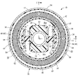
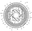
- FIG. 3 is a cross-sectional view showing the engine mount as the first embodiment of the present invention, corresponding to the II cross section of FIG. 2; II-II sectional view of FIG.
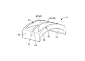
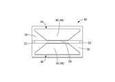
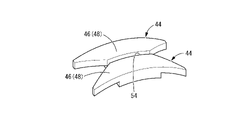
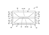
- FIG. 2 is a perspective view of an orifice member that constitutes the engine mount shown in FIG. 1; 4 is a front view of the orifice member shown in FIG. 3; FIG. FIG. 5 is a bottom view of the orifice member shown in FIG. 4; FIG. 5 is a side view of the orifice member shown in FIG. 4; 2 is a perspective view of a magnetic path forming member constituting the orifice member shown in FIG. 1; FIG.
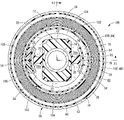
- Sectional view showing an engine mount as a second embodiment of the present invention 9 is a perspective view of an orifice member constituting the engine mount shown in FIG. 8;
- FIG. FIG. 10 is a front view of the orifice member shown in FIG. 9;
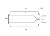
- FIG. 13 is a cross-sectional view showing an engine mount as a third embodiment of the present invention, corresponding to the XI-XI cross section of FIG. 12;
- FIG. 12 is a front view of an orifice member that constitutes the engine mount shown in FIG. 11;
- FIG. 14 is a bottom view of the orifice member shown in FIG. 13;
- FIG. 14 is a side view of the orifice member shown in FIG. 13;
- FIG. 18 is a perspective view showing the engine mount shown in FIG. 17 without the outer tubular member attached;
- the engine mount 10 is a fluid-filled vibration isolator and includes a vibration isolator body 12 .
- the vibration isolator main body 12 has a structure in which an inner shaft member 14 and an outer tubular member 16 are connected by a main rubber elastic body 18 .
- the axial direction refers to the horizontal direction in FIG. 1, which is the central axial direction of the mount
- the vertical direction refers to the vertical direction in FIG. 2, which is the main vibration input direction.
- the inner shaft member 14 has a substantially cylindrical shape with a small diameter and extends linearly in the axial direction.
- the inner shaft member 14 is desirably made of a non-magnetic material, such as stainless steel or an aluminum alloy.
- a stopper member 20 is fixed to the central portion of the inner shaft member 14 in the axial direction.
- the stopper member 20 has an annular shape as a whole, and as shown in FIG. I have.
- An intermediate sleeve 24 is arranged around the inner shaft member 14 as shown in FIGS.
- the intermediate sleeve 24 has a substantially cylindrical shape with a diameter larger than that of the inner shaft member 14 , and is arranged in an extrapolated state away from the inner shaft member 14 along the entire circumference toward the outer peripheral side.
- the intermediate sleeve 24 has windows 26 at two locations in the circumferential direction.
- the window portion 26 radially penetrates the intermediate sleeve 24 at an axially central portion of the intermediate sleeve 24 .
- the groove-shaped portion 28 is a portion of the intermediate sleeve 24 that has a small diameter and is open to the outer peripheral surface. Both ends in the direction reach one of the two windows 26,26.
- the intermediate sleeve 24 is desirably made of a non-magnetic material, such as stainless steel or an aluminum alloy.
- the inner shaft member 14 and the intermediate sleeve 24 are connected by the main rubber elastic body 18 .
- the main rubber elastic body 18 has a substantially cylindrical shape and has an inner peripheral portion fixed to the inner shaft member 14 and an outer peripheral portion fixed to the intermediate sleeve 24 .
- the main rubber elastic body 18 also covers the inner surface of the groove portion 28 of the intermediate sleeve 24 and is also fixed to the outer peripheral surface of the intermediate sleeve 24 at the groove portion 28 .
- the main rubber elastic body 18 can be formed as an integrally vulcanized molded product including the inner shaft member 14 and the intermediate sleeve 24 .
- the main rubber elastic body 18 has two pocket-like portions 30, 30, as shown in FIG.
- the pocket-shaped portion 30 is in the shape of a recess that opens to the outer peripheral surface of the main rubber elastic body 18, and in this embodiment, it opens toward both sides in the vertical direction.
- the pocket-shaped portion 30 is provided at a position corresponding to the window portion 26 of the intermediate sleeve 24 . Open to the side.
- a protruding portion 22 of the stopper member 20 protrudes from the inner peripheral bottom portion of the pocket-shaped portion 30 .
- the outer cylindrical member 16 is externally inserted and fixed to the intermediate sleeve 24 fixed to the main rubber elastic body 18 .
- the outer cylindrical member 16 has a substantially cylindrical shape with a larger diameter than the inner shaft member 14 .
- One end in the axial direction of the outer tubular member 16 is provided with a flange-shaped portion 32 protruding toward the outer peripheral side.
- the outer tubular member 16 is made of a non-magnetic material, such as stainless steel or an aluminum alloy.
- the inner peripheral surface of the outer tubular member 16 is covered with a seal rubber layer 34 .
- the outer cylindrical member 16 is attached to the intermediate sleeve 24 in a state of being externally inserted, and is fitted to the outer peripheral surface of the intermediate sleeve 24 by, for example, diameter reduction processing such as eight-way drawing.
- a seal rubber layer 34 is sandwiched between the outer tubular member 16 and the intermediate sleeve 24 to provide a fluid-tight seal.
- the window portion 26 of the intermediate sleeve 24 is covered with the outer tubular member 16 in a fluid-tight manner.
- two fluid chambers 38, 38, a first fluid chamber 38a and a second fluid chamber 38b are formed between the inner shaft member 14 and the outer cylindrical member 16.
- Each of the fluid chambers 38a and 38b has wall portions on both sides in the axial direction formed by the main rubber elastic body 18.
- a projecting portion 22 of the stopper member 20 protrudes from the radially inner side to the outer side of each of the fluid chambers 38a and 38b.
- the first and second fluid chambers 38a and 38b are spaced apart from each other in the circumferential direction. They are arranged on both sides in the perpendicular direction.
- a magnetic functional fluid is enclosed in each of the fluid chambers 38a and 38b.
- a magnetic functional fluid is a fluid whose viscosity increases under the action of a magnetic field.
- the magnetic functional fluid is any of magneto-rheological fluid (MRF), magnetic fluid (MF), and magnetic composite fluid (MCF) which is a mixture of magneto-rheological fluid and magnetic fluid.
- MRF magneto-rheological fluid
- MF magnetic fluid
- MCF magnetic composite fluid
- the magnetic functional fluid a magneto-rheological fluid whose viscosity changes greatly in response to the action of a magnetic field is desirable, but a magnetic mixed fluid whose viscosity increase width can be easily adjusted by adjusting the mixing ratio of the magneto-rheological fluid and the magnetic fluid is also suitable.
- the magnetic functional fluid is, for example, a suspension or colloidal solution in which ferromagnetic fine particles are dispersed in a base liquid such as water or oil. It is desirable that the surface of the ferromagnetic fine particles is coated with a surfactant, or that the ferromagnetic fine particles are dispersed in a base liquid containing a surfactant.
- the ferromagnetic fine particles are, for example, metal particles such as iron, ferrite, and magnetite, and preferably have a particle diameter of about 8 nm to 10 ⁇ m.
- the base liquid is not particularly limited as long as it can disperse the ferromagnetic fine particles.
- the base liquid is desirably an incompressible fluid.
- the surfactant is appropriately selected according to the base liquid, and for example, oleic acid is preferably used. Note that the magneto-rheological fluid and the magnetic fluid mainly differ in the particle size of the ferromagnetic fine particles, and the magneto-rheological fluid has a larger particle size of the ferromagnetic fine particles than the magnetic fluid.
- the first and second fluid chambers 38a, 38b communicate with each other through an orifice passage 40.
- the orifice passage 40 extends in the circumferential direction between the outer cylindrical member 16 and the intermediate sleeve 24, and both ends in the circumferential direction communicate with one of the first and second fluid chambers 38a and 38b.
- the formation region of the orifice passage 40 is formed by sealing the outer peripheral opening of the groove-shaped portion 28 provided in the intermediate sleeve 24 with the outer tubular member 16 in a fluid-tight manner.
- a pair of orifice passages 40, 40 are provided on both sides of the first fluid chamber 38a in the circumferential direction, and communicate the first fluid chamber 38a and the second fluid chamber 38b in the circumferential direction. are doing.
- the pair of orifice passages 40, 40 are formed on both sides of the direction (horizontal direction in FIG. 2) perpendicular to the facing direction of the first fluid chamber 38a and the second fluid chamber 38b in the direction perpendicular to the central axis of the mount. , and communicates the first fluid chamber 38a and the second fluid chamber 38b in parallel on both sides in the radial direction.
- the first and second fluid chambers 38a, 38b and the orifice passages 40, 40 are arranged side by side in the circumferential direction with good space efficiency, so that the engine mount 10 is suppressed from becoming large.
- the pair of orifice passages 40, 40 are formed with the same passage cross-sectional area and passage length, but the passage cross-sectional area and/or the passage length in both orifice passages may be different from each other. good.
- a side wall portion of the orifice passage 40 is formed by an orifice member 42 .
- the orifice member 42 has a curved plate shape as a whole.
- the orifice member 42 has a pair of magnetic path forming members 44, 44 as shown in FIG.
- the magnetic path forming member 44 is made of a ferromagnetic material such as iron, nickel, chromium, or soft ferrite.
- the orifice member 42 includes a pair of independent magnetic path forming members 44, 44 facing each other with a predetermined distance in the axial direction (vertical direction in FIG. 4).
- the pair of magnetic path forming members 44, 44 of the present embodiment has a 180-degree rotational symmetry shape, and the pair of magnetic path forming members 44, 44 are shared.
- the length dimension in the circumferential direction is smaller at the inner end than the outer end in the opposing direction of the pair of magnetic path forming members 44, 44.
- the magnetic flux concentrating portion 46 is entirely composed of a tapered portion 48 whose length dimension in the circumferential direction gradually decreases toward the inside in the opposing direction.
- the tapered portion 48 of the present embodiment has both ends in the circumferential direction inclined inward in the direction in which the pair of magnetic path forming members 44, 44 oppose each other at substantially the same angle of inclination inward in the circumferential direction. .
- the magnetic path forming member 44 has a circumferential central portion having the same length in the circumferential direction as the inner end of the magnetic flux concentration portion 46 in the opposite direction. It is thicker in the radial direction than the circumferentially outer portion located towards it.
- the entire outer peripheral surface of the magnetic path forming member 44 is a smoothly curved surface positioned on a substantially single cylindrical surface. It is considered thick.
- the magnetic path forming member 44 is desirably made of a soft magnetic material with small residual magnetization.
- the side wall member 50 is made of non-magnetic material, such as synthetic resin, rubber, non-magnetic metal such as aluminum alloy or stainless steel.
- the side wall members 50 are fixed to the axial outer surface and circumferential end surfaces of the magnetic path forming member 44 .
- Circumferential end faces of the side wall member 50 are planes extending substantially parallel to a plane orthogonal to the circumferential direction at the center of the magnetic path forming member 44, and are substantially parallel to each other.
- the side wall members 50 are also positioned on both outer sides in the circumferential direction with respect to the magnetic flux concentration portion 46 (tapered portion 48). , are opposed to each other with a predetermined distance in the axial direction on both outer sides in the circumferential direction of the magnetic flux concentration portion 46 .
- the distance between the pair of magnetic flux concentration units 46 and 46 and the distance between the pair of side wall members 50 and 50 are substantially the same.
- the connecting portion 52 protrudes toward the inner periphery at the circumferential end portions of the side wall members 50, 50, and continues across the pair of side wall members 50, 50 in the axial direction. 50 are integrally connected.
- the connecting portion 52 of this embodiment is integrally formed with the side wall members 50 , 50 .
- the connecting portion 52 is made of non-magnetic material such as synthetic resin, rubber, non-magnetic metal such as aluminum alloy or stainless steel.
- the connecting portions 52 are provided at both ends in the circumferential direction of the side wall members 50, 50. By connecting the side wall members 50, 50 at both ends in the circumferential direction, the shape stability of the orifice member 42 is improved. etc.
- the connecting portion 52 is located outside the magnetic path forming member 44 in the circumferential direction.
- the pair of magnetic path forming members 44, 44 and the pair of side wall members 50, 50 are integrally connected by the connecting portions 52, 52 and mutually positioned, thereby forming the pair of magnetic path forming members 44, 44 in the orifice member 42. 44 and the pair of side wall members 50, 50 are axially opposed to each other.
- the slit-like portion 54 penetrates the orifice member 42 in the radial direction, which is the thickness direction, and opens to the outer peripheral surface and the inner peripheral surface of the orifice member 42 .
- the side wall portion of the slit-shaped portion 54 has a combined structure of the magnetic path forming member 44 made of a ferromagnetic material and the side wall member 50 made of a non-magnetic material. More specifically, the side wall portion of the slit-shaped portion 54 has a central portion in the circumferential direction formed by the magnetic path forming member 44 and both end portions in the circumferential direction formed by the side wall members 50.
- the magnetic path forming members 44, 44 are formed integrally with the side wall members 50, 50 and the connecting portion 52. As shown in FIG. That is, in the orifice member 42 of the present embodiment, the magnetic path forming members 44, 44 are insert-molded into the side wall members 50, 50 and the connecting portion 52, so that the magnetic path forming members 44, 44 are formed into the side wall members 50, 50, 50 and the connecting portion 52 are molded integrally.
- the orifice member 42 is inserted into the groove 28 and attached to the intermediate sleeve 24, as shown in FIGS. That is, the orifice member 42 is positioned in the radial direction by being superimposed on the outer peripheral surface of the intermediate sleeve 24, and the connecting portions 52, 52 protruding toward the inner periphery meet the bottom wall portion of the groove portion 28. are positioned in the circumferential direction with respect to the intermediate sleeve 24 by being superimposed on both circumferential end faces of the intermediate sleeve 24 .
- the outer peripheral surface of the orifice member 42 is overlapped with the inner peripheral surface of the outer tubular member 16 with the seal rubber layer 34 interposed therebetween. is arranged between the intermediate sleeve 24 and the outer tubular member 16 .
- the inner peripheral opening of the slit-shaped portion 54 of the orifice member 42 is covered with the intermediate sleeve 24 by overlapping the inner peripheral surface of the orifice member 42 with the bottom wall portion of the groove-shaped portion 28 of the intermediate sleeve 24 . Since the inner surface of the groove-shaped portion 28 is covered with the rubber layer 56 , the orifice member 42 is pressed against the bottom wall portion of the groove-shaped portion 28 via the rubber layer 56 . The opening is closed in a liquid-tight manner.
- the outer peripheral surface of the orifice member 42 overlaps the inner peripheral surface of the outer cylindrical member 16 via the seal rubber layer 34, so that the outer peripheral opening of the slit-shaped portion 54 of the orifice member 42 is liquid-tightly closed. .
- a tunnel-shaped flow path extending in the circumferential direction is formed using the slit-shaped portion 54. Both ends of the tunnel-shaped flow path in the circumferential direction communicate with one of the first and second fluid chambers 38a and 38b, thereby communicating the first and second fluid chambers 38a and 38b with each other.
- An orifice passage 40 is formed. The orifice passage 40 extends in the circumferential direction of the outer cylindrical member 16 , and the length direction of the orifice passage 40 is the circumferential direction of the outer cylindrical member 16 .
- orifice members 42 are attached to a pair of groove-shaped portions 28, 28 provided on both sides in the radial direction of the intermediate sleeve 24, respectively, and orifice passages 40 are formed in the orifice members 42, respectively.
- the pair of orifice passages 40, 40 may be tuned to the same frequency, or may be tuned to different frequencies. In short, the pair of orifice passages 40, 40 need not have the same size, such as passage cross-sectional area and passage length, and the passage shape.
- a side wall portion of the orifice passage 40 has a combined structure of a magnetic path forming member 44 made of a ferromagnetic material and a side wall member 50 made of a non-magnetic material.
- the passage length of the orifice passage 40 can be set with a large degree of freedom.
- the axially inner tip surface of the magnetic flux concentrator 46 forming the inner surface of the side wall of the orifice passage 40 is such that the dimension in the length direction of the orifice passage 40 is equal to the total length of the orifice passage 40 (the length of the entire orifice passage 40). It is desirable that it is 60% or less of the dimension). More preferably, in the lengthwise direction of the orifice passage 40 , the dimension of the tip surface of the magnetic flux concentration portion 46 is 40% or less of the total length of the orifice passage 40 .
- the axially inner tip surface of the magnetic flux concentration portion 46 may be sharpened so that the dimension in the length direction of the orifice passage 40 is approximately 0. , for example 10% or more of the total length of the orifice passage 40 .
- a magnetic unit 58 is attached to the outer tubular member 16 .
- the magnetic unit 58 has an annular shape as a whole and has a structure in which a yoke member 62 is attached around a coil 60 .
- the magnetic unit 58 generates a magnetic field by energizing the coil 60 .
- the coil 60 has a cylindrical shape or an annular shape as a whole, and has a structure in which an electric wire made of a conductive material is wound.
- the coil 60 is wound around a synthetic resin bobbin.
- the coil 60 is desirably made of a material having excellent electrical conductivity, and is preferably made of, for example, copper or an aluminum alloy.
- the coil 60 is electrically connected to terminals of a connector 66 and is electrically connected to an external energization control device (not shown) via the connector 66 .
- the yoke member 62 is made of a ferromagnetic material such as iron.
- the yoke member 62 has a U-shaped cross section that opens toward the inner periphery, and is arranged to cover both axial end faces and the outer peripheral face of the coil 60 .
- the magnetic flux of the coil 60 is guided to the yoke member 62, which is a ferromagnetic material, that is, the yoke member 62 forms a magnetic path, Magnetic flux leakage to the outer periphery is reduced.
- the yoke member 62 of this embodiment has a split structure so that it can be attached to the coil 60 .
- the magnetic unit 58 is placed outside the outer tubular member 16 so that the inner peripheral surface of the magnetic unit 58 overlaps the outer peripheral surface of the outer tubular member 16 .
- mounted on the outer circumference of the A tubular cover member 70 is arranged around the outer periphery of the magnetic unit 58 , and the magnetic unit 58 is arranged between the outer tubular member 16 and the tubular cover member 70 .
- the cylindrical cover member 70 has a substantially cylindrical shape as a whole and is made of a non-magnetic material such as stainless steel or aluminum alloy. Both axial end portions of the cylindrical cover member 70 protrude toward the inner periphery. are axially positioned with respect to the outer cylindrical member 16 by being overlapped with each other in the axial direction.
- the magnetic unit 58 is axially sandwiched between the flange-shaped portion 32 of the outer tubular member 16 and the other axial end portion of the tubular cover member 70 via a cushioning material such as rubber, so that the outer tubular member 58 is held in place. It is axially positioned relative to member 16 .
- the magnetic unit 58 is sandwiched between the outer tubular member 16 and the tubular cover member 70 in the radial direction and positioned in the radial direction, and is positioned between the flange-shaped portion 32 of the outer tubular member 16 and the tubular cover member 70 . It is fixed to the outer cylindrical member 16 by being axially sandwiched between the other end portion of the axial direction and positioned in the axial direction.
- the engine mount 10 is attached to, for example, a power unit 72, which is one side member to which the inner shaft member 14 is connected in an anti-vibration manner. It is attached to the vehicle by being attached to the vehicle body 74, which is a side member.
- the cylindrical cover member 70 is fixed to the vehicle body 74 by being press-fitted into a mounting hole of the vehicle body 74, for example.
- the inner shaft member 14 may be attached to the power unit 72 via an inner bracket (not shown).
- the tubular cover member 70 may be attached to the vehicle body 74 via an outer bracket (not shown).
- the engine mount 10 is capable of controlling the magnetic field exerted on the magnetic-functional fluid flowing through the orifice passage 40 by means of the magnetic unit 58, thereby controlling the viscosity of the magnetic-functional fluid and providing vibration isolation. Properties can be adjusted or switched. Such control of the viscosity of the magnetic functional fluid by the magnetic unit 58 is realized by controlling the energization of the coil 60 .
- the magnetic field formed around the coil 60 by energizing the coil 60 forms a magnetic pole at the inner peripheral end of the yoke member 62 arranged around the coil 60 . Then, the magnetic flux between the magnetic poles of the yoke member 62 is guided to the magnetic path forming members 44, 44 which are ferromagnets.
- the magnetic path forming members 44, 44 face each other in the axial direction, and the orifice passage 40 is formed between the magnetic path forming members 44, 44. The magnetic flux of the magnetic field passes through the orifice passage 40 .
- the side wall portion of the orifice passage 40 includes the magnetic path forming members 44, 44, the magnetic flux of the magnetic field generated by the magnetic unit 58 is directed to the orifice passage 40 by the magnetic path forming members 44, 44. be guided. Therefore, a magnetic field formed by energizing the coil 60 is exerted on the magnetic functional fluid in the orifice passage 40 .
- the viscosity of the magnetic functional fluid increases according to the strength of the applied magnetic field (magnetic flux density). Therefore, by controlling the intensity of the current flowing through the coil 60, the viscosity of the magnetic functional fluid can be controlled.
- the upper limit of the strength of the magnetic field exerted on the magnetic functional fluid can be adjusted by the number of turns and material of the coil 60, the maximum value of the current flowing through the coil 60, and the like.
- the magnetic path forming members 44, 44 are disposed on both axial side wall portions of the orifice passage 40 extending in the circumferential direction. Therefore, the magnetic flux easily passes through the magnetic functional fluid in the orifice passage 40 extending between the magnetic path forming members 44, 44 facing each other. Therefore, the magnetic force is efficiently applied to the magnetic functional fluid in the orifice passage 40, and the viscosity of the magnetic functional fluid is efficiently controlled by the magnetic unit 58 arranged on the outer periphery of the vibration isolator main body 12. can be done.
- the magnetic path forming members 44, 44 constituting both side wall portions of the orifice passage 40 have a magnetic flux concentration portion 46 that gradually narrows in the longitudinal direction of the orifice passage 40 toward the orifice passage 40 side inward in the facing direction. are provided respectively. Since the cross-sectional area of the magnetic path of the magnetic flux concentration portion 46 gradually decreases toward the orifice passage 40 side, the magnetic flux concentrates at the axial inner end on the orifice passage 40 side, increasing the magnetic flux density. That is, the passage area of the magnetic flux in the orifice passage 40 is limited to the central portion in the length direction of the orifice passage 40, so that high-density magnetic flux can be applied locally to the magnetic functional fluid in the orifice passage 40. .
- High density magnetic flux passing through the magnetic functional fluid within the orifice passage 40 can effectively increase the viscosity of the magnetic functional fluid locally within the orifice passage 40 .
- the flow resistance of the orifice passage 40 can be greatly increased, and the tuning frequency of the orifice passage 40, which is the resonance frequency of fluid flow through the orifice passage 40, can be adjusted with a large degree of freedom.
- the magnetic flux applied to the entire circumferential direction toward the axial outer end of the magnetic path forming member 44 is converged toward the axial inner end at the magnetic flux concentration portion 46, and the magnetic flux density is increased.
- the magnetic functional fluid in the orifice passage 40 is concentrated under these conditions. Therefore, even if the magnetic field generated by the magnetic unit 58 is relatively weak, the magnetic force can act on the magnetic functional fluid in the orifice passage 40 with sufficient magnetic flux density. As a result, it is possible to obtain excellent anti-vibration performance by controlling the viscosity of the magnetic functional fluid while suppressing the power consumption by reducing the current supplied to the coil 60 of the magnetic unit 58 .
- the axially inner tip surface of the magnetic flux concentration part 46 on the orifice passage 40 side has a lengthwise dimension of the orifice passage 40 of 60 mm with respect to the total length of the orifice passage 40 . % or less.
- the length dimension of the tip surface of the magnetic flux concentration portion 46 is 10% or more of the total length of the orifice passage 40, so that the magnetic functional fluid in the orifice passage 40
- the area of action of the magnetic flux for is ensured in the direction of the length of the path, and the anti-vibration characteristics can be effectively adjusted or switched.
- the magnetic flux concentration portion 46 of the present embodiment has a tapered portion 48 as a whole, and the dimension in the passage length direction is continuously reduced toward the tip end face on the orifice passage 40 side.
- the dimension of the tip surface of the magnetic flux concentration portion 46 in the direction of the passage length is reduced to the same degree, A large magnetic path cross-sectional area of the magnetic flux concentration portion 46 can be ensured at the tapered portion 48 .
- the magnetic resistance in the magnetic flux concentration portion 46 can be reduced.
- the magnetic path forming member 44 is desirably made of a soft magnetic material with a small coercive force. The characteristics of 40 can be quickly changed and set according to the input vibration.
- the formation region of the orifice passage 40 is provided between the intermediate sleeve 24 and the outer cylindrical member 16, and both the outer cylindrical member 16 and the intermediate sleeve 24 are made of non-magnetic material.
- magnetic flux can be concentrated on the magnetic path forming member 44 without the outer tubular member 16 and the intermediate sleeve 24 forming a magnetic path. Therefore, a magnetic field can be effectively applied to the magnetic-functional fluid in the orifice passage 40 to control the viscosity of the magnetic-functional fluid.
- the specific mode of adjusting or switching the performance (anti-vibration characteristics) of the engine mount 10 by controlling the viscosity of the magnetic functional fluid flowing through the orifice passage 40 is not particularly limited.
- One mode of control will be exemplified below.
- the coil 60 is not energized and the viscosity of the magnetic functional fluid in the orifice passage 40 is reduced.
- the flow resistance of the magnetic-functional fluid in the orifice passage 40 is reduced, and the low-viscosity magnetic-functional fluid actively flows through the orifice passage 40 .
- the spring characteristics of the engine mount 10 are softened, and good ride comfort is realized by the vibration insulation effect due to the low dynamic spring.
- the coil 60 When a low-frequency, large-amplitude vibration equivalent to engine shake is input, the coil 60 is energized to increase the viscosity of the magnetic functional fluid in the orifice passage 40 .
- the flow resistance of the magnetic-functional fluid increases in the orifice passage 40, and the resonance phenomenon regarding the flow of the magnetic-functional fluid in the orifice passage 40 is exhibited at a lower frequency. Therefore, when the magnetic functional fluid with increased viscosity flows through the orifice passage 40, a vibration damping action against low-frequency vibration is effectively exhibited, and a vibration damping effect is exhibited by damping vibration energy.
- the coil 60 is energized to increase the viscosity of the magnetic functional fluid in the orifice passage 40, thereby stiffening the spring characteristics of the engine mount 10. do.
- the swinging of the power unit 72 can be suppressed, and the steering stability and ride comfort of the vehicle can be improved.
- the engine mount 10 has a soft spring characteristic with excellent vibration insulation and a hard spring with excellent vibration damping performance and support stability of the power unit 72. By appropriately switching the spring characteristics, it is possible to realize excellent anti-vibration performance.
- the ON/OFF switching of the energization of the coil 60 has been exemplified.
- the characteristics of engine mount 10 can also be adjusted. Specifically, for example, in the control example of the characteristics described above, a current is passed through the coil 60 both when engine shake is input and when the power unit 72 rolls. can also be different.
- the power unit 72 undergoes roll displacement, a stronger current may flow than when engine shake is input, so that the roll displacement of the power unit 72 may be more effectively suppressed.
- the idling vibration, engine shake, and roll displacement of the power unit 72 described above are merely examples, and the strength of the current flowing through the coil 60 can be increased according to a wider variety of input vibrations having mutually different amplitudes and frequencies.
- the characteristics of the engine mount 10 can be adjusted in more steps or continuously to achieve excellent anti-vibration performance.
- the energization of the coil 60 may be controlled such that the flow of the magnetic functional fluid is completely blocked in the orifice passage 40 and the orifice passage 40 is substantially cut off.
- FIG. 8 shows an engine mount 80 for an automobile as a second embodiment of a fluid-filled cylindrical vibration damping device constructed according to the present invention.
- the engine mount 80 has an orifice member 82 shown in FIGS.
- members and portions that are substantially the same as those of other embodiments are denoted by the same reference numerals in the drawings, and description thereof is omitted.
- the orifice member 82 has a structure in which a pair of flow path members 88 consisting of the magnetic path forming member 44 and the side wall member 86 are connected to each other at both ends in the circumferential direction by connecting members 90 , 90 .
- the channel member 88 has a structure in which side wall members 86 made of a non-magnetic material are fixed to both the axial and circumferential outer surfaces of the magnetic path forming member 44 made of a ferromagnetic material. is rod-shaped and extends curvedly in the circumferential direction.
- the connecting member 90 is plate-shaped and made of a non-magnetic material.
- the connecting member 90 includes fixed portions 92, 92 superimposed on the circumferential end surfaces of the flow path members 88, 88, and a connecting portion 94 connecting the fixed portions 92, 92.
- the fixed portion 92 has a shape substantially corresponding to the circumferential end surface of the flow path member 88 .
- a threaded hole through which a screw 96 is inserted is formed through the fixed portion 92, and the fixed portions 92, 92 are fixed to the side wall members 86 of the flow path members 88, 88 with a plurality of screws 96, respectively. Thereby, the connecting member 90 and the flow path members 88, 88 are fixed to each other.
- the pair of magnetic path forming members 44, 44 are connected to each other by fixing the connecting members 90, 90 each having a connecting portion 94 by screws after molding.
- the method of fixing the connecting member 90 to the flow path member 88 is not limited to screwing, and may be fixing by adhesion, welding, mechanical locking, or the like, for example.
- the fixed part 92 is connected to each other by a connecting part 94 on the inner circumference of the side wall members 86 , 86 .
- the connecting member 90 By fixing the fixing portions 92, 92 mutually connected by the connecting portion 94 to the circumferential end faces of the side wall members 86, 86, the pair of flow path members 88, 88 are connected to each other by the connecting member 90 to form an orifice.
- a member 82 is constructed.
- the connecting portion 94 of this embodiment is integrally formed with the fixed portions 92 , 92 .
- the connecting member 90 may be provided only at one end in the circumferential direction of the channel members 88, 88, but in the present embodiment, it is provided at both ends in the circumferential direction of the channel members 88, 88.
- the shape stability of the orifice member 82 is improved.
- a groove-like gap 98 penetrating in the circumferential direction is formed between the fixing parts 92 , 92 by providing the connecting part 94 protruding from the side wall members 86 , 86 to the inner periphery.
- a slit-shaped portion 54 formed between the pair of flow path members 88, 88 is opened to both sides in the circumferential direction through gaps 98, 98 provided in connecting members 90, 90 at both ends in the circumferential direction.
- the orifice member 82 having such a structure is attached to the groove-shaped portion 28 of the intermediate sleeve 24 in the same manner as the orifice member 42 of the first embodiment.
- the orifice member 82 is positioned against the intermediate sleeve 24 by overlapping the end of the connecting member 90 projecting inwardly from the flow path members 88 , 88 onto the circumferential end surface of the groove 28 . are positioned in the circumferential direction.
- the orifice passage 40 is formed by closing the inner peripheral opening of the slit-shaped portion 54 with the intermediate sleeve 24 and closing the outer peripheral opening of the slit-shaped portion 54 with the outer cylindrical member 16 .
- the slit-shaped portion 54 communicates with the first and second fluid chambers 38a, 38b through the gaps 98, 98 of the connecting members 90, 90, respectively.
- the engine mount 80 including the orifice member 82 structured according to this embodiment An effect similar to that of the first embodiment can also be obtained with the engine mount 80 including the orifice member 82 structured according to this embodiment.
- the pair of The magnetic path forming members 44, 44 are flow path members 88, 88 having side wall members 86, 86 independent of each other, and the pair of flow path members 88, 88 are connected to each other by separate connecting members 90, 90.
- an orifice member 82 is formed. Therefore, it is possible to form the side wall member 86 and the connecting member 90 from different materials.
- a resin material with excellent moldability is selected, and the cross-sectional area is small.
- a combination of materials can be selected according to the required performance, such as selecting a synthetic resin material with higher strength or a non-magnetic metal material.
- 11 and 12 show an engine mount 100 for an automobile as a third embodiment of a fluid-filled cylindrical vibration damping device constructed according to the present invention.
- the engine mount 100 has an orifice member 102 .
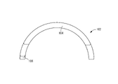
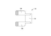
- the orifice member 102 as shown in FIGS. 13 to 16, includes a pair of magnetic path forming members 104, 104 and a connecting portion 106 for connecting the magnetic path forming members 104, 104 to each other.
- the magnetic path forming member 104 is made of a ferromagnetic material and has a curved plate shape extending in the circumferential direction.
- the magnetic path forming member 104 extends in the circumferential direction with a length of approximately half the circumference.
- a magnetic flux concentration part 108 projecting inward in the axial direction is integrally formed at one circumferential end of the magnetic path forming member 104 .
- the magnetic flux concentrating portion 108 has a circumferential length that decreases toward the tip of the protrusion, and a cross-sectional area in a cross section perpendicular to the direction of protrusion (axis-perpendicular cross section) that decreases toward the tip of the protrusion.
- the end surface of the magnetic flux concentration portion 108 on the other side in the circumferential direction is a tapered surface that slopes inward in the axial direction toward one side in the circumferential direction.
- a tapered portion 48 is provided.
- a pair of magnetic path forming members 104, 104 having substantially symmetrical shapes in the axial direction are arranged to face each other while being separated from each other in the axial direction.
- the distance between the pair of magnetic path forming members 104, 104 facing each other is smaller in the facing portions of the magnetic flux concentration portions 108, 108 than in other portions.
- the pair of magnetic path forming members 104, 104 are connected to each other by a connecting portion 106 at the other end in the circumferential direction, thereby forming an orifice member 102.
- the connecting portion 106 is made of, for example, a non-magnetic material such as synthetic resin, and is disposed between the pair of magnetic path forming members 104 and 104 facing each other. It is stuck.
- the connecting portion 106 of the present embodiment extends to the outside of the pair of magnetic path forming members 104, 104 on the other side in the circumferential direction. It is stuck.
- the connecting portion 106 may be fixed to the pair of magnetic path forming members 104, 104 by means of adhesion, welding, or the like after molding, or may be integrally fixed during molding.
- a pair of orifice members 102 having such a structure are arranged to face each other, and the circumferential ends of the pair of orifice members 102 and 102 are butted against each other. and is circular as a whole.
- the circumferential ends provided with the magnetic flux concentrators 108, 108 are butted against each other in the circumferential direction
- the circumferential ends provided with the connecting portions 106, 106 are connected to each other. are abutted against each other in the circumferential direction.
- the pair of orifice members 102, 102 are butted against each other in the circumferential direction on the side of the magnetic flux concentration portions 108, 108, so that the magnetic path forming members 104, 104 on one side in the axial direction are continuous in the circumferential direction as a whole.
- the magnetic path forming members 104, 104 on the other side in the axial direction are also continuous in the circumferential direction and form a C-shaped ring as a whole.
- the magnetic flux concentration part 108 is disposed in the circumferential central portion of the C-shaped annular magnetic path forming members 104, 104 extending in the circumferential direction. , and are connected to each other by connecting portions 106, 106 at both ends in the circumferential direction.
- a pair of annularly arranged orifice members 102, 102 are attached to the intermediate sleeve 24 in an externally inserted state. Both circumferential ends of each orifice member 102 are axially positioned with respect to the intermediate sleeve 24 by being inserted into one of the groove-shaped portions 28 , 28 of the intermediate sleeve 24 .
- the outer tubular member 16 is attached to the pair of orifice members 102 , 102 in an externally inserted state, and the orifice members 102 , 102 are attached to the intermediate sleeve 24 . It is held between outer tubular members 16 .
- the orifice member 102 is arranged so as to straddle the window portion 26 of the intermediate sleeve 24 in the vibration isolator main body 12 in the circumferential direction.
- Two orifice members 102 , 102 are arranged to extend circumferentially through the opening of each window 26 .
- the orifice members 102, 102 may be different parts having different structures, but in this embodiment, they are a common part and are attached to the vibration isolator main body 12 in mutually different directions.
- the slit-shaped portions 54, 54 formed between the opposing magnetic flux concentration portions 108, 108 in each orifice member 102 have their inner peripheral openings covered with the bottom wall portion of the groove-shaped portion 28 in the intermediate sleeve 24, The outer peripheral opening is covered with an outer cylindrical member 16, forming a tunnel-shaped flow path extending in the circumferential direction.
- the tunnel-shaped passages formed by the pair of orifice members 102, 102 are in communication with each other in the circumferential direction, and one end in the circumferential direction of the communicated tunnel-shaped passages is connected to the first fluid chamber 38a. The other end in the circumferential direction is connected to the second fluid chamber 38b.
- an orifice passage 40 that communicates the first and second fluid chambers 38a, 38b with each other is formed using the slit-shaped portions 54, 54.
- a side wall portion of the orifice passage 40 has a structure in which four magnetic path forming members 104, 104, 104, 104 are combined as a whole.
- Each of the magnetic path forming members 104 extends outward in the circumferential direction from the end of the orifice passage 40 in the passage length direction on either side of the orifice passage 40 in the passage length direction in the circumferential direction. extending out.
- the magnetic flux of the magnetic field generated by the magnetic unit 58 when the coil 60 is energized is guided to the magnetic path forming member 104 over substantially the entire circumference in the circumferential direction.
- the magnetic flux guided to the magnetic path forming member 104 is directed to the magnetic flux concentration portion 108 in which the opposing distance between the magnetic path forming members 104, 104 on one side in the axial direction and the magnetic path forming members 104, 104 on the other side in the axial direction is shortened. It converges through the orifice passage 40 which is the opposite portion of 108 .
- FIG. 17 shows an engine mount 110 for an automobile as a fourth embodiment of a fluid-filled tubular vibration damping device constructed according to the present invention.
- the engine mount 110 has an orifice member 112 .
- the orifice member 112 is composed of a pair of magnetic path forming members 114, 114, as also shown in FIG.
- the magnetic path forming member 114 is made of a ferromagnetic material and has an annular shape that is continuous over the entire circumference.
- the magnetic path forming member 114 has a magnetic flux concentration portion 116 that protrudes axially inward in a part of the circumferential direction.
- the magnetic flux concentration portion 116 gradually decreases in circumferential length toward the projecting tip.
- the magnetic flux concentration part 116 of this embodiment has a tapered circumferential end surface, and has a tapered shape in which the cross-sectional area decreases toward the projecting tip.
- the magnetic path forming member 114 is attached to the axial end of the intermediate sleeve 24 in an externally inserted state.
- the magnetic path forming member 114 is fixed to the intermediate sleeve 24 by, for example, press-fitting or diameter reduction processing in an externally inserted state.
- the magnetic path forming members 114 are attached to both ends of the intermediate sleeve 24 in the axial direction, respectively.
- the magnetic flux concentrators 116, 116 are positioned with respect to each other in the circumferential direction and face each other with a predetermined distance in the axial direction.
- the pair of magnetic path forming members 114 , 114 in the orifice member 112 are independent of each other and attached to the intermediate sleeve 24 separately.
- the grooved portion 28 of the intermediate sleeve 24 of this embodiment is filled with a closing rubber 118 integrally formed with the main rubber elastic body 18 .
- a protruding portion of the closing rubber 118 protruding from the groove 28 to the outer periphery is inserted between the opposing portions of the pair of magnetic path forming members 114, 114 where the magnetic flux concentration portions 116, 116 are not provided.
- the pair of magnetic path forming members 114, 114 are axially positioned with respect to the intermediate sleeve 24 by abutting the protruding portion of the closing rubber 118 in the axial direction. .
- the outer cylindrical member 16 is attached to the magnetic path forming members 114, 114 attached to the intermediate sleeve 24 in an externally inserted state.
- the magnetic path forming members 114 , 114 are held between the intermediate sleeve 24 and the outer cylindrical member 16 in the radial direction.
- the slit-shaped portion 54 formed between the magnetic flux concentration portions 116 of the magnetic path forming members 114, 114 in the axial direction has an inner peripheral opening covered with the intermediate sleeve 24 via the closing rubber 118.
- the outer peripheral opening is covered with the outer cylindrical member 16 via the seal rubber layer 34, and the orifice passage 40 extending in the circumferential direction is formed using the slit-shaped portion 54.
- the magnetic flux of the magnetic field generated by the magnetic unit 58 is concentrated by the magnetic flux concentrating portion 116 of the magnetic path forming member 114, and the magnetic function of the orifice passage 40 is achieved in a high-density state. exposed to sexual fluids. Therefore, excellent anti-vibration performance can be obtained by adjusting or switching the characteristics of the orifice passage 40, and power consumption can be reduced by suppressing the power required to form the magnetic field.
- the magnetic path forming member 114 extends outward in the circumferential direction from the orifice passage 40, and the magnetic path forming member 114 has a ring shape that is continuous over the entire circumference.
- the magnetic path forming member 114 is arranged at a position overlapping the magnetic pole forming portion of the yoke member 62 of the magnetic unit 58 in radial projection. Since the distance between the forming member 114 and the magnetic pole forming portion of the yoke member 62 is shortened, leakage magnetic flux between the magnetic path forming member 114 and the yoke member 62 is suppressed.
- the magnetic path forming members 44, 44 on both sides in the axial direction are provided with the magnetic flux concentration portions 46, respectively.
- a structure in which the portion 46 is provided and the other magnetic path forming member 44 is not provided with the magnetic flux concentration portion 46 may also be employed.
- the magnetic flux concentrator 46 does not have a tapered portion 48 whose cross-sectional area changes continuously toward the orifice passage 40 (from the outside to the inside in the axial direction of the mount in the embodiment).
- it may have a stepped shape in which the dimension of the orifice passage 40 in the length direction (circumferential direction) changes stepwise toward the orifice passage 40 .
- the tapered portion 48 may be partially provided in the passage length direction and/or the passage width direction of the orifice passage in the magnetic flux concentration portion 46 .
- the distal end on the side may be tapered and the proximal end remote from the orifice passage 40 may be stepped.
- the height (radial) dimension of the magnetic flux concentration portion 46 may be reduced toward the orifice passage 40 .
- Both ends of the orifice passage 40 in the lengthwise direction of the orifice passage 40 may be stepped or tapered, or only one of the ends may be stepped or tapered (i.e., super-gradient). shape).
- the end portion of the magnetic flux concentration portion 46 on the side of the orifice passage 40 does not necessarily have to have a surface extending in the lengthwise direction of the orifice passage 40. It may be sharpened.
- the magnetic flux concentration portion 46 may have a plurality of tip portions on the side of the orifice passage 40 that constitute the side wall portion of the orifice passage 40 in the longitudinal direction of the orifice passage 40 .
- the sum of the dimensions of the tips of the magnetic flux concentration sections 46 in the length direction of the orifice passage 40 is It is desirable that the length be 60% or less, more preferably 40% or less.
- the magnetic path forming members 44, 44 arranged on both side wall portions of the orifice passage 40 are desirably independent of each other or connected to each other by a connecting portion made of a non-magnetic material. It may be a unitary structure that is integrally connected at the ends. In short, the magnetic path forming members 44, 44 may be connected by a ferromagnetic material as long as the magnetic force acting on the orifice passage 40 is ensured.
- the pair of magnetic flux concentrators 46, 46 forming the side wall portion of the orifice passage 40 are positioned in the circumferential direction to face each other in the facing direction (axial direction) of the side wall portion of the orifice passage 40.
- the magnetic flux concentrators 46, 46 are arranged at mutually different positions in the circumferential direction and are not opposed to each other in the facing direction of the side wall portion of the orifice passage 40. may That is, when providing the magnetic flux concentration portions 46, 46 on both side wall portions of the orifice passage 40, the magnetic flux concentration portions 46, 46 having different shapes and sizes may be adopted, or the magnetic flux concentration portions 46, 46 on both sides may be used.
- the tips of 46, 46 are arranged to face each other at least partially in the orifice width direction (mount axial direction), and are arranged at positions different from each other in the orifice length direction. Therefore, they may be arranged to face each other in an inclined direction with respect to the orifice width direction (mutually shifted in the orifice length direction).
- the orifice passage 40 having a structure extending in the circumferential direction was exemplified.
- the structure is not limited to the structure extending in the circumferential direction without being inclined in the axial direction.
- the magnetic unit 58 can select the magnetic field for the magnetic flux concentration section 46 that constitutes the side wall portion of the orifice passage 40. It may be arranged on the inner peripheral side or inside the inner shaft member, the outer cylindrical member, the main rubber elastic body, or the like, as long as it can exert a controllable effect.
- the magnetic unit may be arranged inside the inner shaft member.
- a storage space for the magnetic unit may be provided inside the outer cylindrical member or inside the main rubber elastic body, or may be arranged on the inner circumference of the hollow inner shaft member.
- the coil of the magnetic unit does not necessarily have to be wound in the circumferential direction over the entire circumference of the outer cylindrical member, and for example, may be arranged so as to be positioned partially in the circumferential direction.
- Engine mount (fluid-filled cylindrical anti-vibration device first embodiment) 12 Anti-vibration device main body 14 inner shaft member 16 outer cylindrical member 18 main rubber elastic body 20 stopper member 22 projecting portion 24 intermediate sleeve 26 window portion 28 groove-shaped portion 30 pocket-shaped portion 32 flange-shaped portion 34 seal rubber layer 38 fluid chamber 40 orifice Passage 42 Orifice member 44 Magnetic path forming member 46 Magnetic flux concentration portion 48 Tapered portion 50 Side wall member 52 Connecting portion 54 Slit portion 56 Rubber layer 58 Magnetic unit 60 Coil 62 Yoke member 66 Connector 70 Cylindrical cover member 72 Power unit 74 Vehicle Body 80 Engine mount (fluid-filled cylindrical anti-vibration device second embodiment) 82 Orifice member 86 Side wall member 88 Flow path member 90 Connecting member 92 Fixing part 94 Connecting part 96 Screw 98 Gap 100 Engine mount (fluid-filled cylindrical vibration isolator third embodiment) 102 Orifice member 104 Magnetic path forming member 106 Connecting portion 108 Magnetic flux concentration portion 110 Engine
Landscapes
- Engineering & Computer Science (AREA)
- General Engineering & Computer Science (AREA)
- Mechanical Engineering (AREA)
- Physics & Mathematics (AREA)
- Electromagnetism (AREA)
- Combined Devices Of Dampers And Springs (AREA)
Abstract
オリフィス通路の流動特性の制御の効率化を図ることが可能になり、例えば消費電力を抑えつつ防振特性を有効に調節又は切替え可能にしたりすることも容易となる、新規な構造の流体封入式筒型防振装置を提供する。 インナ軸部材14とアウタ筒部材16が本体ゴム弾性体18で弾性連結されており、複数の流体室38a,38bがオリフィス通路40によって相互に連通されて設けられている流体封入式筒型防振装置10において、流体室38a,38bの封入流体が磁気機能性流体であり、通電によって磁界を発生する磁気ユニット58を備えており、オリフィス通路40の両側の側壁部分には磁気ユニット58による磁界が及ぼされる磁路形成部材44,44が配されていると共に、磁路形成部材44,44の少なくとも一方には、オリフィス通路40の長さ方向における寸法が対向方向の内方に向かって小さくされた磁束集中化部46が設けられている。
Description
本発明は、内部に封入された流体の流動作用等に基づく防振効果が発揮される流体封入式筒型防振装置に関するものである。
従来から、自動車用のエンジンマウント等に用いられる防振装置の一種として、インナ軸部材とアウタ筒部材が本体ゴム弾性体によって弾性連結された構造を有する筒型防振装置が知られている。また、防振性能の向上等を目的として、内部に封入された流体の流動作用に基づく防振効果を利用する流体封入式筒型防振装置も、従来から知られている。例えば、特開2008-151215号公報(特許文献1)や独国特許出願公開第102011117749号明細書(特許文献2)に開示されており、オリフィス通路を通じた流体流動によって優れた防振性能が発揮される。
ところで、オリフィス通路による防振効果は、オリフィス通路が予めチューニングされた特定周波数の振動に対して有効に発揮される一方、チューニング周波数を外れた周波数域の振動に対しては発揮され難かった。そこで、より広い周波数域の振動に対して有効な防振効果を得るために、例えば、特許文献2では、内部に封入される流体を磁気粘性流体とし、磁気粘性流体に及ぼす磁界の強さを制御することによって、防振特性を切り替えることが検討されている。具体的には、磁気粘性流体に印加する磁界を強くするに従って、磁気粘性流体の粘度が増してオリフィス通路における流動抵抗が大きくなり、オリフィス通路のチューニング周波数がより低周波になる。それゆえ、磁気粘性流体に及ぼす磁界の強さを入力振動の周波数に応じて制御することにより、より広い周波数域の振動入力に対して、オリフィス通路による防振効果を有効に得ることが可能となる。
特許文献2において、より広い周波数域にわたって防振性能を得ようとすると、磁気粘性流体の粘度をより広い範囲で制御するために、より強い磁界を発生させる必要があるが、強い磁界を発生させるためには消費電力量が大きくなってしまう。しかしながら、例えば昨今の自動車は、電装品の増加や高度化が飛躍的に進んでいることによって消費電力量が著しく増大しており、消費電力量の更なる増加を防ぎたいという要求があることから、防振装置に許容される電力消費には限りがあった。
本発明の解決課題は、オリフィス通路の流動特性の制御の効率化を図ることが可能になり、例えば消費電力を抑えつつ防振特性を有効に調節又は切替え可能にしたりすることも容易となる、新規な構造の流体封入式筒型防振装置を提供することにある。
以下、本発明を把握するための好ましい態様について記載するが、以下に記載の各態様は、例示的に記載したものであって、適宜に互いに組み合わせて採用され得るだけでなく、各態様に記載の複数の構成要素についても、可能な限り独立して認識及び採用することができ、適宜に別の態様に記載の何れかの構成要素と組み合わせて採用することもできる。それによって、本発明では、以下に記載の態様に限定されることなく、種々の別態様が実現され得る。
第一の態様は、インナ軸部材とアウタ筒部材が本体ゴム弾性体によって弾性連結されており、流体を封入された複数の流体室がオリフィス通路によって相互に連通されて設けられている流体封入式筒型防振装置において、前記流体室に封入された流体が磁気機能性流体であり、通電によって磁界を発生する磁気ユニットを備えており、前記オリフィス通路において対向する両側の側壁部分には該磁気ユニットによる磁界が及ぼされる磁路形成部材が配されていると共に、かかる両側の側壁部分に配された該磁路形成部材の少なくとも一方には、該オリフィス通路の長さ方向における寸法が対向方向の内方に向かって小さくされた磁束集中化部が設けられているものである。
本態様に従う構造とされた流体封入式筒型防振装置によれば、磁束集中化部による磁束の集中作用によって、オリフィス通路内の磁気機能性流体に対して磁気ユニットが発生する磁力を高い密度で集中的に及ぼすことができる。それゆえ、オリフィス通路の流動特性をより少ない通電量で効率的に制御することが可能となり、例えば消費電力を押えながら要求される防振性能を得ること等も容易になる。
第二の態様は、第一の態様に記載された流体封入式筒型防振装置において、前記オリフィス通路の両側の側壁部分に配された前記磁路形成部材は、互いに独立した部材であり、且つ連結部によって相互に連結されているものである。
本態様に従う構造とされた流体封入式筒型防振装置によれば、一対の磁路形成部材を一体的に取り扱うことが可能になって、防振装置の製造が容易になる。
第三の態様は、第二の態様に記載された流体封入式筒型防振装置において、前記オリフィス通路の両側の側壁部分に配された前記磁路形成部材が強磁性材であり、前記連結部が非磁性材であるものである。
本態様に従う構造とされた流体封入式筒型防振装置によれば、一対の磁路形成部材を相互に連結する連結部が非磁性材とされていることにより、磁束が一対の磁路形成部材間において連結部へ導かれるのを抑えて、一対の磁路形成部材間のオリフィス通路に対して磁力を効率的に及ぼすことができる。
第四の態様は、第二又は第三の何れか1つの態様に記載された流体封入式筒型防振装置において、前記オリフィス通路の両側の側壁部分に配される前記磁路形成部材が、前記連結部と一体的に成形されているものである。
本態様に従う構造とされた流体封入式筒型防振装置によれば、例えば、一対の磁路形成部材に対して連結部を一体的に成形することにより、一対の磁路形成部材を連結部で容易に連結することができる。なお、例えば、連結部に対して一対の磁路形成部材を一体的に成形することにより、一対の磁路形成部材を連結部で容易に連結することもできる。
第五の態様は、第二又は第三の態様に記載された流体封入式筒型防振装置において、前記オリフィス通路の両側の側壁部分に配される前記磁路形成部材に対して、別部材からなる前記連結部が後固着されることによって、該オリフィス通路の両側の側壁部分に配された該磁路形成部材が連結されているものである。
本態様に従う構造とされた流体封入式筒型防振装置によれば、一対の磁路形成部材と連結部が別部材とされていることから、それら一対の磁路形成部材と連結部をそれぞれ容易に製造することができる。
第六の態様は、第一~第五の何れか1つの態様に記載された流体封入式筒型防振装置において、前記オリフィス通路の両側の側壁部分が、前記磁路形成部材と非磁性材からなる側壁部材との組み合わせ構造とされており、該オリフィス通路の該側壁部分を長さ方向で部分的に該磁路形成部材が構成しているものである。
本態様に従う構造とされた流体封入式筒型防振装置によれば、オリフィス通路の長さ方向における磁束集中化部の寸法を小さくして磁束の集中化を図りつつ、防振特性上必要とされるオリフィス通路の通路長さを非磁性材からなる側壁部材によって確保することができる。
第七の態様は、第一~第六の何れか1つの態様に記載された流体封入式筒型防振装置において、前記オリフィス通路の両側の側壁部分に配された前記磁路形成部材が互いに対称形状とされているものである。
本態様に従う構造とされた流体封入式筒型防振装置によれば、両側の磁路形成部材にそれぞれ磁束集中化部が設けられており、それら両側の磁束集中化部が対向配置されることから、両側の磁束集中化部の対向配置部分において磁力がオリフィス通路内の磁気機能性流体へ効率的に及ぼされる。
第八の態様は、第一~第七の何れか1つの態様に記載された流体封入式筒型防振装置において、前記磁路形成部材における前記磁束集中化部は、前記オリフィス通路の長さ方向における寸法が対向方向の内方に向かって次第に小さくされたテーパー状部分を有しているものである。
本態様に従う構造とされた流体封入式筒型防振装置によれば、オリフィス通路の長さ方向における磁束集中化部の寸法をオリフィス通路の側壁部の対向方向内方の端部において小さくしながら、磁路形成部材のボリュームを容易に確保することができる。
第九の態様は、第一~第八の何れか1つの態様に記載された流体封入式筒型防振装置において、前記磁路形成部材が、前記オリフィス通路の長さ方向の少なくとも一方の側において、該オリフィス通路よりも外方にまで延びだしているものである。
本態様に従う構造とされた流体封入式筒型防振装置によれば、オリフィス通路の長さ方向において磁路形成部材がより長く設けられることによって、より広い範囲の磁束が磁束集中化部へ導かれて、オリフィス通路内の磁気機能性流体に対して磁力をより集中して効率的に及ぼすことができる。
第十の態様は、第九の態様に記載された流体封入式筒型防振装置において、前記磁路形成部材は、前記オリフィス通路の周方向両端部からそれぞれ周方向外方に向かって延びて、全体として前記アウタ筒部材の周方向に延びる環状とされているものである。
本態様に従う構造とされた流体封入式筒型防振装置によれば、オリフィス通路の長さ方向でオリフィス通路よりも外方にまで延び出す磁路形成部材が、全体としてアウタ筒部材の周方向に延びる環状とされることにより、筒型防振装置において長い磁路形成部材を収容するスペースを確保し易い。
第十一の態様は、第十の態様に記載された流体封入式筒型防振装置において、前記本体ゴム弾性体の外周部分に中間スリーブが固着されており、全体として環状とされた前記磁路形成部材が該中間スリーブに外挿状態で取り付けられていると共に、該磁路形成部材に対して前記アウタ筒部材が外挿状態で取り付けられているものである。
本態様に従う構造とされた流体封入式筒型防振装置によれば、磁路形成部材が中間スリーブとアウタ筒部材の間に保持されることから、磁路形成部材を容易に取り付けることができると共に、磁路形成部材を安定した支持態様で配することができる。
第十二の態様は、第一~第十一の何れか1つの態様に記載された流体封入式筒型防振装置において、前記磁路形成部材の前記磁束集中化部における対向方向内方の先端面は、前記オリフィス通路の長さ方向の寸法が該オリフィス通路の全長に対して60%以下とされているものである。
本態様に従う構造とされた流体封入式筒型防振装置によれば、オリフィス通路の長さ方向において、磁束集中化部における対向方向内方の先端面の寸法が、オリフィス通路の全長に対して十分に小さくされて、オリフィス通路内の磁気機能性流体に対して磁力を集中的に及ぼすことができる。
本発明によれば、流体封入式筒型防振装置において、オリフィス通路の流動特性の制御の効率化が図られ得て、例えば消費電力を抑えつつ防振特性を有効に調節する又は切り替えるような要求などにも対応することが容易となる。
以下、本発明の実施形態について、図面を参照しつつ説明する。
図1,図2には、本発明に従う構造とされた防振装置の第一の実施形態として、自動車用のエンジンマウント10が示されている。エンジンマウント10は、流体封入式の防振装置であって、防振装置本体12を備えている。防振装置本体12は、インナ軸部材14とアウタ筒部材16が、本体ゴム弾性体18によって連結された構造を有している。以下の説明において、原則として、軸方向とはマウント中心軸方向である図1中の左右方向を、上下方向とは主たる振動入力方向である図2中の上下方向を、それぞれ言う。
インナ軸部材14は、小径の略円筒形状とされており、軸方向において直線的に延びている。インナ軸部材14は、非磁性材料によって形成されていることが望ましく、例えば、ステンレス鋼やアルミニウム合金等によって形成されている。インナ軸部材14の軸方向中央部分には、ストッパ部材20が固定されている。ストッパ部材20は、全体として環状とされており、図2に示すように、後述する2つの流体室38,38が配される上下方向の両側に向けて突出する2つの突出部22,22を備えている。
インナ軸部材14の周囲には、図1,図2に示すように、中間スリーブ24が配されている。中間スリーブ24は、インナ軸部材14よりも大径の略円筒形状とされており、インナ軸部材14に対して全周において外周側へ離れた外挿状態で配置されている。中間スリーブ24は、周方向の2箇所にそれぞれ窓部26を備えている。窓部26は、中間スリーブ24の軸方向中央部分において中間スリーブ24を径方向に貫通している。中間スリーブ24における2つの窓部26,26の周方向間には、それぞれ溝状部28が設けられている。溝状部28は、中間スリーブ24において部分的に小径とされて外周面に開口する凹溝状とされた部分であって、中間スリーブ24の軸方向中央部分を周方向に延びており、周方向の両端部が2つの窓部26,26の各一方まで達している。中間スリーブ24は、インナ軸部材14と同様に非磁性材料によって形成されていることが望ましく、例えば、ステンレス鋼やアルミニウム合金等によって形成されている。
インナ軸部材14と中間スリーブ24は、本体ゴム弾性体18によって連結されている。本体ゴム弾性体18は、略円筒形状であって、内周部分がインナ軸部材14に固着されていると共に、外周部分が中間スリーブ24に固着されている。また、本体ゴム弾性体18は、中間スリーブ24における溝状部28の溝内面を覆っており、溝状部28において中間スリーブ24の外周面にも固着されている。本体ゴム弾性体18は、インナ軸部材14と中間スリーブ24を備える一体加硫成形品として形成され得る。
本体ゴム弾性体18は、図2に示すように、2つのポケット状部30,30を備えている。ポケット状部30は、本体ゴム弾性体18の外周面に開口する凹所状とされており、本実施形態では上下方向の両側に向けて開口している。ポケット状部30は、中間スリーブ24の窓部26と対応する位置に設けられて、ポケット状部30の開口周縁部が窓部26に固着されており、ポケット状部30が窓部26を通じて外周側へ向けて開放されている。ポケット状部30の内周底部には、ストッパ部材20の突出部22が突出している。
本体ゴム弾性体18に固着された中間スリーブ24には、アウタ筒部材16が外挿固定されている。アウタ筒部材16は、インナ軸部材14よりも大径の略円筒形状とされている。アウタ筒部材16の軸方向一方の端部は、外周側へ向けて突出するフランジ状部32を備えている。アウタ筒部材16は、非磁性材料によって形成されており、例えば、ステンレス鋼やアルミニウム合金等によって形成されている。アウタ筒部材16の内周面は、シールゴム層34によって覆われている。
アウタ筒部材16は、中間スリーブ24に対して外挿状態で装着されており、例えば、八方絞りなどの縮径加工によって中間スリーブ24の外周面に嵌着されている。また、アウタ筒部材16と中間スリーブ24の間は、シールゴム層34が挟まれることによって、流体密に封止されている。
中間スリーブ24の窓部26は、アウタ筒部材16によって流体密に覆われている。これにより、インナ軸部材14とアウタ筒部材16の間には、2つの流体室38,38として第一の流体室38a及び第二の流体室38bが形成されている。各流体室38a,38bは、軸方向両側の壁部が本体ゴム弾性体18によって構成されている。また、各流体室38a,38bには、径方向の内側から外側へ向けてストッパ部材20の突出部22が突出している。第一及び第二の流体室38a,38bは、周方向で相互に離れて設けられており、本実施形態では、インナ軸部材14に対して上下方向の両側、即ちマウント中心軸に対して軸直角方向の両側に配されている。
各流体室38a,38bには、磁気機能性流体が封入されている。磁気機能性流体は、磁界の作用によって粘度が増大する流体である。磁気機能性流体は、磁気粘性流体(Magneto-Rheological Fluid;MRF),磁性流体(Magnetic Fluid;MF),磁気粘性流体と磁性流体を混合した磁気混合流体(Magnetic Composite Fluid;MCF)の何れであってもよい。磁気機能性流体としては、磁界の作用に対して粘度が大きく変化する磁気粘性流体が望ましいが、磁気粘性流体と磁性流体の混合比率によって粘度の増大幅を容易に調節可能な磁気混合流体も好適に採用される。
磁気機能性流体は、例えば、水や油などのベース液に強磁性微粒子を分散させた懸濁液又はコロイド溶液であって、強磁性微粒子がベース液内において凝集や沈降を生じ難いように、強磁性微粒子の表面が界面活性剤によって被覆されている、或いは強磁性微粒子が界面活性剤を添加したベース液内に分散されていることが望ましい。
強磁性微粒子は、例えば、鉄,フェライト,磁鉄鉱(マグネタイト)等の金属粒子であって、好適には、8nm~10μm程度の粒子径とされている。ベース液は、強磁性微粒子を分散させることが可能であれば、特に限定されないが、例えば、水,イソパラフィン,アルキルナフタレン,パーフルオロポリエーテル,ポリオレフィン,シリコーンオイル等が採用可能である。また、ベース液は、非圧縮性流体であることが望ましい。界面活性剤は、ベース液に応じて適宜に選択され、例えば、オレイン酸等が好適に採用される。なお、磁気粘性流体と磁性流体は、主として強磁性微粒子の粒子径が異なり、磁気粘性流体は磁性流体よりも強磁性微粒子の粒子径が大きい。
第一及び第二の流体室38a,38bは、オリフィス通路40によって相互に連通されている。オリフィス通路40は、アウタ筒部材16と中間スリーブ24の間を周方向に延びており、周方向の両端部が第一及び第二の流体室38a,38bの各一方に連通されている。オリフィス通路40の形成領域は、中間スリーブ24に設けられた溝状部28の外周開口が、アウタ筒部材16によって流体密に封止されることによって形成されている。本実施形態では、一対のオリフィス通路40,40が、第一の流体室38aの周方向両側に設けられており、第一の流体室38aと第二の流体室38bとをそれぞれ周方向で連通している。一対のオリフィス通路40,40は、マウント中心軸の軸直角方向において、第一の流体室38aと第二の流体室38bの対向方向に対して直交する方向(図2中の左右方向)の両側に設けられており、第一の流体室38aと第二の流体室38bとを径方向の両側で並列的に連通している。第一及び第二の流体室38a,38bとオリフィス通路40,40は、周方向に並んでスペース効率よく配されており、エンジンマウント10の大型化が抑えられている。更に、本実施形態では、一対のオリフィス通路40,40が相互に等しい通路断面積と通路長をもって形成されているが、両オリフィス通路における通路断面積及び/又は通路長は相互に異ならされてもよい。
また、オリフィス通路40の側壁部分は、オリフィス部材42によって形成されている。オリフィス部材42は、図3~図6に示すように、全体として湾曲板状とされている。オリフィス部材42は、図7に示すような一対の磁路形成部材44,44を備えている。
磁路形成部材44は、鉄、ニッケル、クロム、ソフトフェライト等の強磁性材によって形成されている。オリフィス部材42は、軸方向(図4中の上下方向)において所定の距離を隔てて対向する相互に独立した一対の磁路形成部材44,44を備えている。本実施形態の一対の磁路形成部材44,44は、180度の回転対称形状とされており、一対の磁路形成部材44,44の共通化が図られている。一対の磁路形成部材44,44は、周方向の長さ寸法が一対の磁路形成部材44,44の対向方向の外端よりも内端において小さくされており、対向方向の内方に向けて周方向の長さ寸法が小さくされた磁束集中化部46をそれぞれ備えている。磁束集中化部46は、対向方向の内方へ向けて周方向の長さ寸法が次第に小さくなるテーパー状部分48によって全体が構成されている。本実施形態のテーパー状部分48は、周方向の両端がそれぞれ一対の磁路形成部材44,44の対向方向内方へ向けて周方向の内側へ略同じ大きさの傾斜角で傾斜している。磁路形成部材44は、磁束集中化部46の対向方向内端と周方向長さが同じとされた周方向の中央部分が、磁束集中化部46の対向方向内端よりも周方向の外方に位置する周方向の外側部分よりも、径方向において厚肉とされている。磁路形成部材44は、外周面の全体が略単一円筒面上に位置する滑らかな湾曲面とされており、周方向の中央部分は周方向の外側部分よりも内周へ突出することで厚肉とされている。磁路形成部材44は、残留磁化の小さい軟磁性体であることが望ましい。
一対の磁路形成部材44,44には、それぞれ側壁部材50が固着されており、それら側壁部材50,50が周方向の両端部に一体形成された連結部52,52によって相互に連結されている。これにより、相互に独立した部材である一対の磁路形成部材44,44が、側壁部材50,50を介して連結部52,52によって連結されて、オリフィス部材42が構成されている。
側壁部材50は、非磁性材とされており、例えば合成樹脂、ゴム、アルミニウム合金やステンレス鋼のような非磁性金属などによって形成されている。側壁部材50は、磁路形成部材44の軸方向の外面及び周方向の両端面に固着されている。側壁部材50の周方向の両端面は、磁路形成部材44の周方向中央における周方向に対する直交平面と略平行に広がる平面とされており、相互に略平行とされている。側壁部材50は、磁束集中化部46(テーパー状部分48)に対して周方向の両外側にも位置しており、一対の磁路形成部材44,44に固着された側壁部材50,50が、磁束集中化部46よりも周方向の両外側において軸方向で所定の距離を隔てて相互に対向している。一対の磁束集中化部46,46の対向間距離と、一対の側壁部材50,50の対向間距離は、略同じとされている。
連結部52は、側壁部材50,50の周方向端部において内周へ向けて突出しており、一対の側壁部材50,50に跨って軸方向に連続することにより、それら一対の側壁部材50,50を一体的に連結している。そして、一対の磁路形成部材44,44が一対の側壁部材50,50を介して連結部52によって相互に連結されることにより、一対の磁路形成部材44,44及び一対の側壁部材50,50を備えたオリフィス部材42が形成されている。本実施形態の連結部52は、側壁部材50,50と一体形成されている。連結部52は、非磁性材とされており、例えば合成樹脂、ゴム、アルミニウム合金やステンレス鋼のような非磁性金属などによって形成されている。連結部52は、側壁部材50,50の周方向の両端部にそれぞれ設けられており、側壁部材50,50が周方向の両端部において連結されることで、オリフィス部材42の形状安定性の向上等が図られている。連結部52は、磁路形成部材44よりも周方向の外側に位置している。
一対の磁路形成部材44,44及び一対の側壁部材50,50が連結部52,52によって一体的に連結されて相互に位置決めされることにより、オリフィス部材42における一対の磁路形成部材44,44及び一対の側壁部材50,50の軸方向対向間には、周方向に延びるスリット状部54が形成されている。スリット状部54は、オリフィス部材42の厚さ方向である径方向に貫通しており、オリフィス部材42の外周面と内周面にそれぞれ開口している。スリット状部54の側壁部分は、強磁性材からなる磁路形成部材44と非磁性材からなる側壁部材50との組み合わせ構造とされている。より具体的には、スリット状部54の側壁部分は、周方向の中央部分が磁路形成部材44によって構成されていると共に、周方向の両端部分が側壁部材50によって構成されている、
かくの如き構造とされたオリフィス部材42は、磁路形成部材44,44が側壁部材50,50及び連結部52と一体的に成形されている。即ち、本実施形態のオリフィス部材42は、磁路形成部材44,44が側壁部材50,50及び連結部52に対してインサート成形されることにより、磁路形成部材44,44が側壁部材50,50及び連結部52と一体的に成形されている。
オリフィス部材42は、図1,図2に示すように、溝状部28に差し入れられて中間スリーブ24に取り付けられている。即ち、オリフィス部材42は、中間スリーブ24の外周面に重ね合わされることにより、径方向で位置決めされていると共に、内周へ向けて突出する連結部52,52が溝状部28の底壁部の周方向両端面に重ね合わされることにより、中間スリーブ24に対して周方向で位置決めされている。そして、中間スリーブ24にアウタ筒部材16が外挿状態で装着されることにより、オリフィス部材42の外周面がアウタ筒部材16の内周面にシールゴム層34を介して重ね合わされて、オリフィス部材42が中間スリーブ24とアウタ筒部材16の間に配されている。
オリフィス部材42の内周面が中間スリーブ24の溝状部28の底壁部に重ね合わされることにより、オリフィス部材42のスリット状部54の内周開口が中間スリーブ24によって覆われる。溝状部28の内面がゴム層56によって覆われていることにより、オリフィス部材42が溝状部28の底壁部にゴム層56を介して押し当てられており、スリット状部54の内周開口が液密に閉塞される。
また、オリフィス部材42の外周面がアウタ筒部材16の内周面に対してシールゴム層34を介して重ね合わされることにより、オリフィス部材42のスリット状部54の外周開口が液密に閉塞される。
これらにより、中間スリーブ24とアウタ筒部材16の間には、スリット状部54を利用して形成された周方向に延びるトンネル状の流路が形成されている。そして、トンネル状の流路の周方向両端部が第一,第二の流体室38a,38bの各一方に連通されており、それによって第一,第二の流体室38a,38bを相互に連通するオリフィス通路40が形成されている。オリフィス通路40はアウタ筒部材16の周方向に延びており、オリフィス通路40の長さ方向がアウタ筒部材16の周方向とされている。本実施形態では、中間スリーブ24における径方向両側に設けられた一対の溝状部28,28に対してそれぞれオリフィス部材42が取り付けられており、それらオリフィス部材42にそれぞれオリフィス通路40が形成されている。なお、一対のオリフィス通路40,40は、互いに同じ周波数にチューニングされていてもよいし、互いに異なる周波数にチューニングされていてもよい。要するに、一対のオリフィス通路40,40は、通路断面積や通路長さなどのサイズや通路形状などが互いに同じである必要はない。
オリフィス通路40は、軸方向両側の側壁部分がオリフィス部材42におけるスリット状部54の側壁部分によって構成されている。従って、オリフィス通路40の側壁部分は、オリフィス通路40の通路長さ方向における中央部分が部分的に磁路形成部材44の磁束集中化部46によって構成されていると共に、磁路形成部材44に対する通路長さ方向の両側がそれぞれ側壁部材50によって構成されている。オリフィス通路40の側壁部分は、強磁性材からなる磁路形成部材44と、非磁性材からなる側壁部材50との組み合わせ構造とされている。磁束集中化部46の軸方向内端における通路長さ方向での長さ寸法が小さくされていても、磁束集中化部46に対して通路長さ方向の両側に配される側壁部材50によって、オリフィス通路40の通路長さを大きな自由度で設定することができる。
オリフィス通路40の側壁内面を構成する磁束集中化部46の軸方向内方の先端面は、オリフィス通路40の通路長さ方向の寸法が、オリフィス通路40の全長(オリフィス通路40全体の通路長さ寸法)に対して60%以下とされていることが望ましい。より好適には、オリフィス通路40の通路長さ方向において、磁束集中化部46の先端面の寸法は、オリフィス通路40の全長の40%以下とされる。磁束集中化部46の軸方向内方の先端面は、オリフィス通路40の通路長さ方向の寸法が略0とされた先鋭状であってもよいが、好適には、通路長さ方向においてある程度の寸法で延びていることが望ましく、例えば、オリフィス通路40の全長に対して10%以上とされる。
アウタ筒部材16には、磁気ユニット58が取り付けられている。磁気ユニット58は、全体として円環状とされており、コイル60の周囲にヨーク部材62が取り付けられた構造を有している。そして、磁気ユニット58は、コイル60への通電によって、磁界を発生する。
コイル60は、全体として円筒形状乃至は円環形状とされており、導電性材料で形成された電線が巻き回された構造とされている。コイル60は、合成樹脂製のボビンに巻き付けられて形成されている。コイル60は、電気伝導性に優れた材料によって形成されていることが望ましく、好適には、例えば銅やアルミニウム合金などによって形成される。なお、コイル60は、コネクタ66の端子に導通されており、図示しない外部の通電制御装置に対してコネクタ66を介して電気的に接続される。
ヨーク部材62は、鉄などの強磁性材料によって形成されている。ヨーク部材62は、内周へ向けて開放されたU字状断面を有しており、コイル60の軸方向両端面及び外周面を覆うように配されている。これにより、コイル60に対して周方向の電流が流れると、コイル60の磁束が強磁性体であるヨーク部材62に導かれて、即ちヨーク部材62により磁路が形成されて、軸方向外側及び外周への磁束の漏れが低減される。本実施形態のヨーク部材62は、コイル60への装着を可能とするために、分割構造とされている。
磁気ユニット58は、図1,図2に示すように、アウタ筒部材16に対して外挿配置されて、内周面がアウタ筒部材16の外周面に重ね合わされた状態で、アウタ筒部材16の外周側に装着されている。磁気ユニット58の外周には筒状カバー部材70が配されており、磁気ユニット58がアウタ筒部材16と筒状カバー部材70の間に配されている。
筒状カバー部材70は、全体として略円筒形状とされており、ステンレス鋼やアルミニウム合金等の非磁性材料によって形成されている。筒状カバー部材70は、軸方向の両端部が内周へ向けて突出しており、アウタ筒部材16に外挿された状態において、軸方向一方の端部がアウタ筒部材16のフランジ状部32と軸方向で重ね合わされることにより、アウタ筒部材16に対して軸方向で位置決めされている。また、磁気ユニット58は、アウタ筒部材16のフランジ状部32と筒状カバー部材70の軸方向他方の端部との軸方向間でゴム等の緩衝材を介して挟み込まれることにより、アウタ筒部材16に対して軸方向で位置決めされている。要するに、磁気ユニット58は、アウタ筒部材16と筒状カバー部材70との径方向間で挟持されて径方向において位置決めされていると共に、アウタ筒部材16のフランジ状部32と筒状カバー部材70の軸方向他方の端部との軸方向間で挟持されて軸方向において位置決めされていることにより、アウタ筒部材16に対して固設されている。
エンジンマウント10は、例えば、インナ軸部材14が防振連結される一方側の部材であるパワーユニット72に取り付けられ、アウタ筒部材16に固定された筒状カバー部材70が、防振連結される他方側の部材である車両ボデー74に取り付けられることにより、車両に取り付けられる。筒状カバー部材70は、例えば、車両ボデー74の装着孔に圧入されるなどして、車両ボデー74に固定される。なお、インナ軸部材14は、図示しないインナブラケットを介してパワーユニット72に取り付けられてもよい。同様に、筒状カバー部材70は、図示しないアウタブラケットを介して車両ボデー74に取り付けられてもよい。
エンジンマウント10の車両への取付状態において、第一及び第二の流体室38a,38bが配された上下方向の振動がエンジンマウント10へ入力されると、第一及び第二の流体室38a,38bの間においてオリフィス通路40を通じた封入流体の流動が生じて、流体の流動作用に基づいた防振効果が発揮される。
エンジンマウント10は、オリフィス通路40を流れる磁気機能性流体に及ぼされる磁界を、磁気ユニット58によって制御することが可能とされており、それによって、磁気機能性流体の粘度を制御して、防振特性を調節する又は切り替えることができる。このような磁気ユニット58による磁気機能性流体の粘度の制御は、コイル60への通電を制御することによって実現される。
すなわち、コイル60への通電によってコイル60の周囲に形成される磁界は、コイル60の周囲に配されたヨーク部材62の内周端に磁極を形成する。そして、ヨーク部材62の磁極間の磁束は、強磁性体である磁路形成部材44,44へ導かれる。磁路形成部材44,44は軸方向において相互に対向しており、磁路形成部材44,44の間にオリフィス通路40が形成されていることから、磁路形成部材44,44に及ぼされた磁界の磁束は、オリフィス通路40を通過する。換言すれば、オリフィス通路40の側壁部分が磁路形成部材44,44を含んで構成されていることにより、磁気ユニット58が発生する磁界の磁束が磁路形成部材44,44によってオリフィス通路40へ導かれる。それゆえ、オリフィス通路40内の磁気機能性流体には、コイル60への通電によって形成される磁界が及ぼされる。
磁気機能性流体は、及ぼされる磁界の強さ(磁束密度)に応じて粘度が増大する。それゆえ、コイル60に流れる電流の強さを制御することによって、磁気機能性流体の粘性を制御することができる。磁気機能性流体に及ぼされる磁界の強さの上限は、コイル60の巻き数や材質、コイル60に流れる電流の最大値等によって調節され得る。
本実施形態では、周方向に延びるオリフィス通路40の軸方向両側の側壁部分に磁路形成部材44,44が配されており、それら磁路形成部材44,44が近接して対向配置されていることから、それら磁路形成部材44,44の対向間を延びるオリフィス通路40内の磁気機能性流体を磁束が通過し易い。それゆえ、オリフィス通路40内の磁気機能性流体に磁力が効率的に及ぼされて、防振装置本体12の外周に配された磁気ユニット58によって磁気機能性流体の粘度を効率的に制御することができる。
オリフィス通路40の両側壁部分を構成する磁路形成部材44,44は、対向方向内方であるオリフィス通路40側へ向けてオリフィス通路40の長さ方向で次第に幅狭となる磁束集中化部46をそれぞれ備えている。磁束集中化部46は、オリフィス通路40側へ向けて次第に磁路の断面積が小さくなることから、オリフィス通路40側である軸方向内端において磁束が集中して磁束密度が高くなる。即ち、オリフィス通路40における磁束の通過領域がオリフィス通路40の長さ方向の中央部分に限定されて、オリフィス通路40内の磁気機能性流体に対して高密度の磁束を局所的に及ぼすことができる。高密度の磁束がオリフィス通路40内の磁気機能性流体を通過することにより、磁気機能性流体の粘度をオリフィス通路40内で局所的に効率よく高めることができる。その結果、オリフィス通路40の流動抵抗を大幅に高めることが可能であり、オリフィス通路40を通じた流体流動の共振周波数であるオリフィス通路40のチューニング周波数を大きな自由度で調節することができる。
このように、磁路形成部材44の軸方向外端に対して周方向の全体に及ぼされる磁束が、磁束集中化部46において軸方向内端へ向けて収束されて、磁束密度が高められた状態でオリフィス通路40内の磁気機能性流体に集中的に作用する。それゆえ、磁気ユニット58が発生する磁界が比較的に弱くても、オリフィス通路40内の磁気機能性流体に対して十分な磁束密度で磁力を作用させることができる。その結果、磁気ユニット58のコイル60に通電される電流を低減して消費電力を抑えながら、磁気機能性流体の粘度の制御による優れた防振性能を得ることができる。
本実施形態において、磁束集中化部46のオリフィス通路40側の先端面である軸方向内方の先端面は、オリフィス通路40の通路長さ方向の寸法が、オリフィス通路40の全長に対して60%以下とされている。これにより、オリフィス通路40に対して長さ方向で局所的に強い磁力を及ぼすことができて、目的とする防振特性の調節や切替えを効率的に実現することができる。また、オリフィス通路40の通路長さ方向において、磁束集中化部46の先端面の長さ寸法が、オリフィス通路40全長の10%以上とされていることにより、オリフィス通路40内の磁気機能性流体に対する磁束の作用領域が通路長さ方向で確保されて、防振特性を有効に調節する乃至は切り替えることができる。
本実施形態の磁束集中化部46は、全体がテーパー状部分48とされており、オリフィス通路40側の先端面に向けて通路長さ方向の寸法が連続的に小さくなっている。これにより、通路長さ方向の寸法が段階的に変化する段差状の磁束集中化部に比して、磁束集中化部46の先端面の通路長さ方向の寸法を同等程度に小さくしながら、磁束集中化部46の磁路断面積をテーパー状部分48において大きく確保することができる。磁路断面積が大きく確保されることによって、磁束集中化部46における磁気抵抗を小さくすることができる。
磁路形成部材44は、保持力が小さい軟磁性体であることが望ましく、これによれば、コイル60への通電の制御に対して磁路形成部材44の磁化が精度よく追従し、オリフィス通路40の特性を入力振動に応じて速やかに変更設定することができる。
オリフィス通路40の形成領域は、中間スリーブ24とアウタ筒部材16の間に設けられており、アウタ筒部材16と中間スリーブ24が何れも非磁性材とされている。これにより、アウタ筒部材16や中間スリーブ24が磁路を形成することがなく、磁路形成部材44に磁束を集中させることができる。それゆえ、オリフィス通路40内の磁気機能性流体に対して磁界を効率的に及ぼして、磁気機能性流体の粘度を制御することができる。
なお、オリフィス通路40を流れる磁気機能性流体の粘度を制御することによるエンジンマウント10の性能(防振特性)の調節又は切替えの具体的な態様は、特に限定されず、要求性能を満たすように制御すればよいが、以下に制御の一態様を例示する。
まず、中乃至高周波の振動が入力されるアイドリング振動の入力時や通常の走行状態においては、コイル60への通電がなされず、オリフィス通路40内の磁気機能性流体の粘度が小さくされる。これにより、オリフィス通路40における磁気機能性流体の流動抵抗が小さくなり、オリフィス通路40を通じて低粘性の磁気機能性流体が積極的に流動する。その結果、エンジンマウント10のばね特性が柔らかくされて、低動ばね化による振動絶縁効果によって良好な乗り心地が実現される。
エンジンシェイクに相当する低周波の大振幅振動が入力される際には、コイル60に通電することによって、オリフィス通路40内の磁気機能性流体の粘度を増大させる。これにより、オリフィス通路40において磁気機能性流体の流動抵抗が大きくなって、オリフィス通路40における磁気機能性流体の流動に関する共振現象が、より低周波において発現される。それゆえ、粘度が増大した磁気機能性流体がオリフィス通路40を流動することによって、低周波振動に対する振動減衰作用が効果的に発揮されて、振動エネルギーの減衰による防振効果が発揮される。
また、車両の急発進等によってパワーユニット72が大きくロール変位する場合には、コイル60に通電して、オリフィス通路40における磁気機能性流体の粘度を大きくすることにより、エンジンマウント10のばね特性を硬くする。これにより、パワーユニット72の揺動を抑え、車両の操縦安定性や乗り心地の向上を実現することができる。
このように、エンジンマウント10は、入力振動に応じてコイル60への通電を制御することにより、振動絶縁性に優れた柔らかいばね特性と、振動減衰性能やパワーユニット72の支持安定性に優れた硬いばね特性とを適宜に切り替えて、優れた防振性能を実現することができる。本実施形態では、コイル60への通電のON/OFFの切替えについて例示したが、コイル60に対する通電のON/OFFを制御するだけでなく、コイル60に流す電流の強さを制御することによって、エンジンマウント10の特性を調節することもできる。具体的には、例えば、上記した特性の制御例において、エンジンシェイクの入力時とパワーユニット72のロール変位時は、何れもコイル60に電流が流されるが、コイル60に流す電流の強さを相互に異ならせることもできる。即ち、例えば、パワーユニット72のロール変位時には、エンジンシェイクの入力時よりも強い電流が流されて、パワーユニット72のロール変位がより効果的に抑制されるようにしてもよい。また、上述したアイドリング振動、エンジンシェイク、パワーユニット72のロール変位は、あくまでも例示であって、振幅や周波数が相互に異なるより多種類の入力振動に応じて、コイル60に流す電流の強さをより多段階に或いは連続的に制御すれば、エンジンマウント10の特性をより多段階に或いは連続的に調節して、優れた防振性能を実現することもできる。なお、オリフィス通路40において磁気機能性流体の流動が完全に阻止されて、オリフィス通路40が実質的に遮断されるように、コイル60への通電を制御してもよい。
図8には、本発明に従う構造とされた流体封入式筒型防振装置の第二の実施形態として、自動車用のエンジンマウント80が示されている。エンジンマウント80は、図9,図10に示すオリフィス部材82を備えている。以下の説明において、他の実施形態と実質的に同一の部材及び部位については、図中に同一の符号を付すことにより、説明を省略する。
オリフィス部材82は、磁路形成部材44と側壁部材86からなる流路部材88の一対が、連結部材90,90によって周方向両端部において相互に連結された構造を有している。流路部材88は、強磁性材からなる磁路形成部材44の軸方向外面及び周方向両外面に非磁性材からなる側壁部材86が固着された構造を有しており、略長手板状乃至はロッド状とされて、周方向に湾曲して延びている。
連結部材90は、板状とされており、非磁性材によって形成されている。連結部材90は、流路部材88,88の各周方向端面に重ね合わされる固定部92,92と、それら固定部92,92をつなぐ連結部94とを、備えている。固定部92は、流路部材88の周方向端面と略対応する形状とされている。固定部92にはねじ96が挿通されるねじ穴が貫通形成されており、固定部92,92が各流路部材88,88の各側壁部材86に対してそれぞれ複数のねじ96で固定されることによって、連結部材90と流路部材88,88が相互に固定されている。従って、本実施形態において、一対の磁路形成部材44,44は、それぞれ連結部94を備える連結部材90,90が成形後にねじ止めによって後固着されることにより、相互に連結されている。なお、連結部材90の流路部材88に対する固定方法は、ねじ止めに限定されず、例えば、接着、溶着、機械的な係止等による固定であってもよい。
固定部92は、側壁部材86,86よりも内周において連結部94で相互に連結されている。連結部94によって相互に連結された固定部92,92が側壁部材86,86の周方向端面に固定されることにより、一対の流路部材88,88が連結部材90によって相互に連結されてオリフィス部材82が構成されている。本実施形態の連結部94は、固定部92,92と一体形成されている。連結部材90は、流路部材88,88の周方向一方の端部にのみ設けられていてもよいが、本実施形態では流路部材88,88の周方向両端部にそれぞれ設けられており、オリフィス部材82の形状安定性の向上が図られている。
連結部94が側壁部材86,86から内周へ突出して設けられていることにより、固定部92,92の間には、周方向に貫通する溝状の隙間98が形成されている。そして、一対の流路部材88,88の間に形成されるスリット状部54が、周方向両端の連結部材90,90に設けられた隙間98,98を通じて周方向両側へ開放されている。
かくの如き構造とされたオリフィス部材82は、前記第一の実施形態のオリフィス部材42と同様に、中間スリーブ24の溝状部28に取り付けられる。オリフィス部材82は、流路部材88,88よりも内周へ突出した連結部材90の端部が、溝状部28の周方向端面に重ね合わされることにより、オリフィス部材82が中間スリーブ24に対して周方向で位置決めされている。
スリット状部54の内周開口が中間スリーブ24によって閉塞されると共に、スリット状部54の外周開口がアウタ筒部材16によって閉塞されることにより、オリフィス通路40が形成される。スリット状部54は、連結部材90,90の隙間98,98を通じて第一,第二の流体室38a,38bに連通されている。
このような本実施形態に従う構造とされたオリフィス部材82を備えるエンジンマウント80によっても、第一の実施形態と同様の効果を得ることができる。また、一対の磁路形成部材44,44が側壁部材50,50と一体形成された連結部52,52によって一体的に連結された第一の実施形態のオリフィス部材42に比して、一対の磁路形成部材44,44が互いに独立した側壁部材86,86を備える流路部材88,88とされて、一対の流路部材88,88が別体の連結部材90,90によって相互に連結されることでオリフィス部材82が形成されている。それゆえ、側壁部材86と連結部材90を異なる材質で形成することが可能であり、例えば、耐荷重性が求められ難い側壁部材86は成形性に優れた樹脂材料を選択し、断面積が小さい連結部94への入力による損傷が問題となり得る連結部材90は、より高強度の合成樹脂材料や非磁性金属材料を選択する等、要求性能に応じた材質の組み合わせを選択することができる。
図11,図12には、本発明に従う構造とされた流体封入式筒型防振装置の第三の実施形態として、自動車用のエンジンマウント100が示されている。
エンジンマウント100は、オリフィス部材102を備えている。オリフィス部材102は、図13~図16に示すように、一対の磁路形成部材104,104と、それら磁路形成部材104,104を相互に連結する連結部106とを、備えている。
磁路形成部材104は、強磁性材によって形成されており、周方向に延びる湾曲板状とされている。磁路形成部材104は、周方向に略半周の長さで延びている。磁路形成部材104の周方向一方の端部には、軸方向の内側へ向けて突出する磁束集中化部108が一体形成されている。磁束集中化部108は、突出先端に向けて周方向の長さ寸法が小さくされており、突出方向と直交する断面(軸直角断面)における断面積が突出先端へ向けて小さくなっている。磁束集中化部108の周方向他方側の端面は、軸方向内方へ向けて周方向一方側へ傾斜するテーパー面とされており、磁束集中化部108が軸方向内側へ向けて先細形状のテーパー状部分48とされている。
オリフィス部材102において、軸方向で略対称形状とされた一対の磁路形成部材104,104が、軸方向で相互に離れて対向配置されている。一対の磁路形成部材104,104の対向間の距離は、磁束集中化部108,108の対向部分において他の部分よりも小さくされている。
一対の磁路形成部材104,104は、図13,16に示すように、周方向他方の端部において連結部106によって相互に連結されており、それによってオリフィス部材102が構成されている。連結部106は、例えば合成樹脂等の非磁性材によって構成されており、一対の磁路形成部材104,104の対向間に配されて、それら一対の磁路形成部材104,104の対向内面に固着されている。本実施形態の連結部106は、一対の磁路形成部材104,104よりも周方向他方側の外方まで延び出しており、一対の磁路形成部材104,104の周方向他方側の端面に固着されている。なお、連結部106は、一対の磁路形成部材104,104に対して、成形後に接着や溶着等の手段で固定されてもよいし、成形時に一体的に固着されてもよい。
このような構造とされたオリフィス部材102は、図11,図12に示すように、一対が向かい合わせに配されており、それら一対のオリフィス部材102,102の周方向端部が相互に突き合わされて、全体として環状とされている。一対のオリフィス部材102,102は、磁束集中化部108,108が設けられた周方向端部同士が周方向において相互に突き合わされていると共に、連結部106,106が設けられた周方向端部同士が周方向において相互に突き合わされている。一対のオリフィス部材102,102が磁束集中化部108,108側において周方向で相互に突き合わされていることにより、軸方向一方側の磁路形成部材104,104が周方向に連続して全体としてC字環状とされていると共に、軸方向他方側の磁路形成部材104,104も周方向に連続して全体としてC字環状とされている。要するに、周方向に延びるC字環状とされた磁路形成部材104,104の周方向中央部分に磁束集中化部108が配されており、それら磁路形成部材104,104の一対は、軸方向で相互に離れて対向配置されていると共に、周方向両端部において連結部106,106によって相互に連結されている。
環状に配された一対のオリフィス部材102,102は、中間スリーブ24に対して外挿状態で取り付けられている。各オリフィス部材102の周方向両端部は、中間スリーブ24の溝状部28,28の各一方に挿し入れられることによって、軸方向で中間スリーブ24に対して位置決めされている。そして、中間スリーブ24にアウタ筒部材16が装着されることにより、アウタ筒部材16が一対のオリフィス部材102,102に対して外挿状態で取り付けられて、オリフィス部材102,102が中間スリーブ24とアウタ筒部材16の間で保持されている。
オリフィス部材102は、防振装置本体12における中間スリーブ24の窓部26を周方向に跨ぐように配されている。2つのオリフィス部材102,102が各窓部26の開口部分を周方向に延びるように配されている。オリフィス部材102,102は、互いに構造が異なる別部品とされていてもよいが、本実施形態では共通の部品とされており、相互に異なる向きで防振装置本体12に取り付けられている。
各オリフィス部材102における磁束集中化部108,108の対向間に形成されたスリット状部54,54は、内周開口が中間スリーブ24における溝状部28の底壁部によって覆われていると共に、外周開口がアウタ筒部材16によって覆われており、周方向に延びるトンネル状の流路となっている。一対のオリフィス部材102,102によって構成されるトンネル状の流路は周方向で相互に連通されており、それら連通されたトンネル状の通路の周方向一方の端部が第一の流体室38aに接続されていると共に、周方向他方の端部が第二の流体室38bに接続されている。これにより、第一,第二の流体室38a,38bを相互に連通するオリフィス通路40がスリット状部54,54を利用して形成されている。オリフィス通路40の側壁部分は、全体が4つの磁路形成部材104,104,104,104の組み合わせ構造とされている。各磁路形成部材104は、何れも、オリフィス通路40の通路長さ方向である周方向の何れか一方側において、オリフィス通路40の通路長さ方向の端部よりも周方向の外方にまで延び出している。
このようなオリフィス部材102,102を備えたエンジンマウント100は、コイル60への通電によって磁気ユニット58が発生する磁界の磁束が、周方向の略全周にわたって磁路形成部材104へ導かれる。磁路形成部材104へ導かれた磁束は、軸方向一方の磁路形成部材104,104と軸方向他方の磁路形成部材104,104との対向間距離が短くされた磁束集中化部108,108の対向部分であるオリフィス通路40を集中的に通過する。これにより、オリフィス通路40内の磁気機能性流体に対して磁束が集中的に及ぼされて、磁気機能性流体に対して局所的に磁束密度の高い磁力が及ぼされることから、磁気機能性流体の粘度を効率的に制御することができる。その結果、オリフィス通路40の流動抵抗等を効率的に制御することができて、オリフィス通路40のチューニング周波数ひいてはエンジンマウント100の防振特性の調節又は切替えが可能になる。このように、本実施形態の構造によれば、第一,第二の実施形態に比して、周方向のより広い範囲の磁束をオリフィス通路40へ導いて磁気機能性流体により強い磁力を及ぼすことができることから、防振特性の有効な調節又は切替えをより少ない消費電力で実現することができる。
図17には、本発明に従う構造とされた流体封入式筒型防振装置の第四の実施形態として、自動車用のエンジンマウント110が示されている。
エンジンマウント110は、オリフィス部材112を備えている。オリフィス部材112は、図18にも示すように、一対の磁路形成部材114,114によって構成されている。磁路形成部材114は、強磁性材からなり、全周にわたって連続する環状とされている。磁路形成部材114は、周方向の一部において軸方向内側へ向けて突出する磁束集中化部116を備えている。磁束集中化部116は、突出先端へ向けて周方向長さが次第に小さくなっている。本実施形態の磁束集中化部116は、周方向端面がテーパー面とされており、突出先端へ向けて断面積が小さくなる先細形状とされている。
磁路形成部材114は、中間スリーブ24の軸方向端部に外挿状態で取り付けられている。磁路形成部材114は、中間スリーブ24に対して、例えば圧入や外挿状態での縮径加工等によって固定される。磁路形成部材114は、中間スリーブ24の軸方向両端部に対してそれぞれ取り付けられており、それら一対の磁路形成部材114,114は、軸方向で相互に離れて対向配置されていると共に、磁束集中化部116,116が周方向において相互に位置決めされて軸方向で所定距離を隔てて対向している。オリフィス部材112において一対の磁路形成部材114,114は相互に独立しており、中間スリーブ24に対して各別に取り付けられている。なお、本実施形態の中間スリーブ24の溝状部28は、本体ゴム弾性体18と一体形成された閉塞ゴム118によって充填されている。また、一対の磁路形成部材114,114における磁束集中化部116,116が設けられていない部分の対向間には、溝状部28から外周へ突出した閉塞ゴム118の突出部分が入り込んでおり、一対の磁路形成部材114,114が閉塞ゴム118の当該突出部分に軸方向で当接することによって、一対の磁路形成部材114,114が中間スリーブ24に対して軸方向で位置決めされている。
中間スリーブ24に取り付けられた磁路形成部材114,114には、図17に示すように、アウタ筒部材16が外挿状態で取り付けられている。これにより、磁路形成部材114,114は、中間スリーブ24とアウタ筒部材16の径方向間に保持されている。また、磁路形成部材114,114の磁束集中化部116,116の軸方向間に形成されたスリット状部54は、内周開口が閉塞ゴム118を介して中間スリーブ24で覆われていると共に、外周開口がシールゴム層34を介してアウタ筒部材16で覆われており、スリット状部54を利用して周方向に延びるオリフィス通路40が形成されている。
このような構造を有する本実施形態のエンジンマウント110においても、磁気ユニット58の発生磁界の磁束が磁路形成部材114の磁束集中化部116によって集中した高密度な状態でオリフィス通路40の磁気機能性流体に及ぼされる。それゆえ、オリフィス通路40の特性の調節又は切替えによる優れた防振性能を得ることができると共に、磁界を形成するために必要な電力を抑えることで消費電力量を低減することができる。
本実施形態では、磁路形成部材114がオリフィス通路40よりも周方向外側まで延び出しており、磁路形成部材114が全周にわたって連続する環状とされている。これにより、周方向全周の磁束が磁路形成部材114によってオリフィス通路40内へ導かれて、オリフィス通路40内の磁気機能性流体により強い磁力を効率的に及ぼすことができる。しかも、本実施形態では、図17に示すように、磁路形成部材114が、磁気ユニット58のヨーク部材62における磁極形成部分に対して、径方向投影において重なる位置に配されており、磁路形成部材114とヨーク部材62における磁極形成部分との距離が短くされていることから、磁路形成部材114とヨーク部材62の間における漏れ磁束が抑えられる。
以上、本発明の実施形態について詳述してきたが、本発明はその具体的な記載によって限定されない。例えば、前記実施形態では、軸方向両側の磁路形成部材44,44の両方に磁束集中化部46がそれぞれ設けられた構造について説明したが、何れか一方の磁路形成部材44に磁束集中化部46が設けられ、何れか他方の磁路形成部材44には磁束集中化部46が設けられていない構造も採用され得る。
磁束集中化部46は、オリフィス通路40側に向けて(実施形態ではマウント軸方向外方から内方に向けて)断面積が連続的に変化するテーパー形状のテーパー状部分48を備えていなくてもよく、例えば、オリフィス通路40へ向けてオリフィス通路40の長さ方向(周方向)の寸法が段階的に変化する段差形状であってもよい。また、テーパー状部分48は、磁束集中化部46においてオリフィス通路の通路長さ方向及び/又は通路幅方向で部分的に設けられていてもよく、例えば、磁束集中化部46は、オリフィス通路40側の先端部がテーパー状部分48とされると共に、オリフィス通路40から離れた基端部が段差状とされ得る。また、磁束集中化部46は、オリフィス通路40の長さ方向の寸法に加えて、高さ方向(径方向)の寸法が、オリフィス通路40へ向けて小さくされていてもよい。テーパー状部分は、オリフィス通路40の通路長さ方向における両端部が何れも段差状やテーパー状とされていてもよいし、何れか一方の端部だけが段差状やテーパー状(即ち、片勾配状)とされていてもよい。
磁束集中化部46のオリフィス通路40側の端部は、必ずしもオリフィス通路40の長さ方向に延びる面を有している必要はなく、例えば、オリフィス通路40の長さ方向の寸法が略0とされた先鋭状であってもよい。
磁束集中化部46は、オリフィス通路40の側壁部分を構成するオリフィス通路40側の先端部が、オリフィス通路40の長さ方向で複数あってもよい。なお、複数の磁束集中化部46がオリフィス通路40の側壁部分を構成する場合には、オリフィス通路40の長さ方向において、磁束集中化部46の先端部の寸法の総和が、オリフィス通路40の長さ寸法に対して、60%以下、より好適には40%以下とされることが望ましい。
オリフィス通路40の両側の側壁部分に配された磁路形成部材44,44は、互いに独立しているか、非磁性材の連結部によって相互に連結されていることが望ましいが、例えば、周方向の端部において一体的に連結された一体構造であってもよい。要するに、磁路形成部材44,44は、オリフィス通路40に作用する磁力が確保されれば、強磁性材によって連結されていてもよい。
前記実施形態では、オリフィス通路40の側壁部分を構成する一対の磁束集中化部46,46が、周方向で相互に位置決めされて、オリフィス通路40の側壁部分の対向方向(軸方向)で対向して配置されている例を示したが、例えば、磁束集中化部46,46は、周方向で相互に異なる位置に配されて、オリフィス通路40の側壁部分の対向方向で相互に対向していなくてもよい。即ち、オリフィス通路40の両側壁部分に磁束集中化部46,46を設けるに際して、互いに異なる形状や大きさの磁束集中化部46,46を採用してもよいし、それら両側の磁束集中化部46,46における各先端部(オリフィス通路40側の端部)は、オリフィス幅方向(マウント軸方向)で少なくとも一部で対向配置されている他、オリフィス長さ方向で互いに異なる位置に配されることでオリフィス幅方向に対して(オリフィス長さ方向に相互にずれて)傾斜方向で対向配置されていてもよい。
前記実施形態では、周方向に延びる構造のオリフィス通路40を例示したが、オリフィス通路は、例えば、軸方向に傾斜しながら周方向に延びていたり、蛇行しながら周方向に延びていたり、軸方向に延びていたりしてもよく、軸方向で傾斜することなく周方向に延びる構造だけに限定されるものではない。
前記実施形態では、磁気ユニット58がアウタ筒部材16の外周面に取り付けられた構造を例示したが、磁気ユニットは、オリフィス通路40の側壁部分を構成する磁束集中化部46に磁界を選択可能又は制御可能に及ぼし得るものであればよく、例えばインナ軸部材やアウタ筒部材、本体ゴム弾性体等の内周側や内部に配置されていてもよい。例えば、特開2020-133700号公報に示されているように、磁気ユニットはインナ軸部材の内部に配されていてもよい。また、アウタ筒部材の内部や本体ゴム弾性体の内部に磁気ユニットの収容スペースを設けることもできるし、中空とされたインナ軸部材の内周に配してもよい。また、磁気ユニットのコイルは、必ずしもアウタ筒部材の全周にわたって周方向に巻回されていなくてもよく、例えば、周方向で部分的に位置するように配されていてもよい。
10 エンジンマウント(流体封入式筒型防振装置 第1実施形態)
12 防振装置本体
14 インナ軸部材
16 アウタ筒部材
18 本体ゴム弾性体
20 ストッパ部材
22 突出部
24 中間スリーブ
26 窓部
28 溝状部
30 ポケット状部
32 フランジ状部
34 シールゴム層
38 流体室
40 オリフィス通路
42 オリフィス部材
44 磁路形成部材
46 磁束集中化部
48 テーパー状部分
50 側壁部材
52 連結部
54 スリット状部
56 ゴム層
58 磁気ユニット
60 コイル
62 ヨーク部材
66 コネクタ
70 筒状カバー部材
72 パワーユニット
74 車両ボデー
80 エンジンマウント(流体封入式筒型防振装置 第二の実施形態)
82 オリフィス部材
86 側壁部材
88 流路部材
90 連結部材
92 固定部
94 連結部
96 ねじ
98 隙間
100 エンジンマウント(流体封入式筒型防振装置 第三の実施形態)
102 オリフィス部材
104 磁路形成部材
106 連結部
108 磁束集中化部
110 エンジンマウント(流体封入式筒型防振装置 第四の実施形態)
112 オリフィス部材
114 磁路形成部材
116 磁束集中化部
118 閉塞ゴム
12 防振装置本体
14 インナ軸部材
16 アウタ筒部材
18 本体ゴム弾性体
20 ストッパ部材
22 突出部
24 中間スリーブ
26 窓部
28 溝状部
30 ポケット状部
32 フランジ状部
34 シールゴム層
38 流体室
40 オリフィス通路
42 オリフィス部材
44 磁路形成部材
46 磁束集中化部
48 テーパー状部分
50 側壁部材
52 連結部
54 スリット状部
56 ゴム層
58 磁気ユニット
60 コイル
62 ヨーク部材
66 コネクタ
70 筒状カバー部材
72 パワーユニット
74 車両ボデー
80 エンジンマウント(流体封入式筒型防振装置 第二の実施形態)
82 オリフィス部材
86 側壁部材
88 流路部材
90 連結部材
92 固定部
94 連結部
96 ねじ
98 隙間
100 エンジンマウント(流体封入式筒型防振装置 第三の実施形態)
102 オリフィス部材
104 磁路形成部材
106 連結部
108 磁束集中化部
110 エンジンマウント(流体封入式筒型防振装置 第四の実施形態)
112 オリフィス部材
114 磁路形成部材
116 磁束集中化部
118 閉塞ゴム
Claims (12)
- インナ軸部材とアウタ筒部材が本体ゴム弾性体によって弾性連結されており、流体を封入された複数の流体室がオリフィス通路によって相互に連通されて設けられている流体封入式筒型防振装置において、
前記流体室に封入された流体が磁気機能性流体であり、
通電によって磁界を発生する磁気ユニットを備えており、
前記オリフィス通路において対向する両側の側壁部分には該磁気ユニットによる磁界が及ぼされる磁路形成部材が配されていると共に、
かかる両側の側壁部分に配された該磁路形成部材の少なくとも一方には、該オリフィス通路の長さ方向における寸法が対向方向の内方に向かって小さくされた磁束集中化部が設けられている流体封入式筒型防振装置。 - 前記オリフィス通路の両側の側壁部分に配された前記磁路形成部材は、互いに独立した部材であり、且つ連結部によって相互に連結されている請求項1に記載の流体封入式筒型防振装置。
- 前記オリフィス通路の両側の側壁部分に配された前記磁路形成部材が強磁性材であり、前記連結部が非磁性材である請求項2に記載の流体封入式筒型防振装置。
- 前記オリフィス通路の両側の側壁部分に配される前記磁路形成部材が、前記連結部と一体的に成形されている請求項2又は3に記載の流体封入式筒型防振装置。
- 前記オリフィス通路の両側の側壁部分に配される前記磁路形成部材に対して、別部材からなる前記連結部が後固着されることによって、該オリフィス通路の両側の側壁部分に配された該磁路形成部材が連結されている請求項2又は3に記載の流体封入式筒型防振装置。
- 前記オリフィス通路の両側の側壁部分が、前記磁路形成部材と非磁性材からなる側壁部材との組み合わせ構造とされており、該オリフィス通路の該側壁部分を長さ方向で部分的に該磁路形成部材が構成している請求項1~5の何れか一項に記載の流体封入式筒型防振装置。
- 前記オリフィス通路の両側の側壁部分に配された前記磁路形成部材が互いに対称形状とされている請求項1~6の何れか一項に記載の流体封入式筒型防振装置。
- 前記磁路形成部材における前記磁束集中化部は、前記オリフィス通路の長さ方向における寸法が対向方向の内方に向かって次第に小さくされたテーパー状部分を有している請求項1~7の何れか一項に記載の流体封入式筒型防振装置。
- 前記磁路形成部材が、前記オリフィス通路の長さ方向の少なくとも一方の側において、該オリフィス通路よりも外方にまで延びだしている請求項1~8の何れか一項に記載の流体封入式筒型防振装置。
- 前記磁路形成部材は、前記オリフィス通路の長さ方向両端部からそれぞれ周方向外方に向かって延びて、全体として前記アウタ筒部材の周方向に延びる環状とされている請求項9に記載の流体封入式筒型防振装置。
- 前記本体ゴム弾性体の外周部分に中間スリーブが固着されており、
全体として環状とされた前記磁路形成部材が該中間スリーブに外挿状態で取り付けられていると共に、該磁路形成部材に対して前記アウタ筒部材が外挿状態で取り付けられている請求項10に記載の流体封入式筒型防振装置。 - 前記磁路形成部材の前記磁束集中化部における対向方向内方の先端面は、前記オリフィス通路の長さ方向の寸法が該オリフィス通路の全長に対して60%以下とされている請求項1~11の何れか一項に記載の流体封入式筒型防振装置。
Priority Applications (3)
| Application Number | Priority Date | Filing Date | Title |
|---|---|---|---|
| DE112022002230.2T DE112022002230T5 (de) | 2021-07-15 | 2022-03-30 | Flüssigkeitsgefüllte rohrförmige schwingungsdämpfungsvorrichtung |
| CN202280037134.3A CN117377837A (zh) | 2021-07-15 | 2022-03-30 | 流体封入式筒型防振装置 |
| US18/462,423 US20230407940A1 (en) | 2021-07-15 | 2023-09-07 | Fluid-filled cylindrical vibration damping device |
Applications Claiming Priority (2)
| Application Number | Priority Date | Filing Date | Title |
|---|---|---|---|
| JP2021117390A JP2023013310A (ja) | 2021-07-15 | 2021-07-15 | 流体封入式筒型防振装置 |
| JP2021-117390 | 2021-07-15 |
Related Child Applications (1)
| Application Number | Title | Priority Date | Filing Date |
|---|---|---|---|
| US18/462,423 Continuation US20230407940A1 (en) | 2021-07-15 | 2023-09-07 | Fluid-filled cylindrical vibration damping device |
Publications (1)
| Publication Number | Publication Date |
|---|---|
| WO2023286397A1 true WO2023286397A1 (ja) | 2023-01-19 |
Family
ID=84919309
Family Applications (1)
| Application Number | Title | Priority Date | Filing Date |
|---|---|---|---|
| PCT/JP2022/016195 Ceased WO2023286397A1 (ja) | 2021-07-15 | 2022-03-30 | 流体封入式筒型防振装置 |
Country Status (5)
| Country | Link |
|---|---|
| US (1) | US20230407940A1 (ja) |
| JP (1) | JP2023013310A (ja) |
| CN (1) | CN117377837A (ja) |
| DE (1) | DE112022002230T5 (ja) |
| WO (1) | WO2023286397A1 (ja) |
Cited By (1)
| Publication number | Priority date | Publication date | Assignee | Title |
|---|---|---|---|---|
| DE102023104481A1 (de) | 2022-06-27 | 2023-12-28 | Sumitomo Riko Company Limited | Antivibrationsvorrichtung |
Families Citing this family (1)
| Publication number | Priority date | Publication date | Assignee | Title |
|---|---|---|---|---|
| JP7724734B2 (ja) * | 2022-03-04 | 2025-08-18 | 住友理工株式会社 | 流体封入式防振装置 |
Citations (5)
| Publication number | Priority date | Publication date | Assignee | Title |
|---|---|---|---|---|
| JP2011153691A (ja) * | 2010-01-28 | 2011-08-11 | Keihin Corp | 能動型防振装置 |
| JP2014525011A (ja) * | 2011-07-12 | 2014-09-25 | ベイジンウェスト・インダストリーズ・カンパニー・リミテッド | 振動源を支持する液圧マウント装置 |
| JP2015505014A (ja) * | 2012-08-15 | 2015-02-16 | ベイジンウェスト・インダストリーズ・カンパニー・リミテッドBeijingwest Industries Co., Ltd. | マウント装置 |
| JP2020133703A (ja) * | 2019-02-15 | 2020-08-31 | 本田技研工業株式会社 | 可変剛性ブッシュ |
| WO2021240908A1 (ja) * | 2020-05-27 | 2021-12-02 | 住友理工株式会社 | 防振装置 |
Family Cites Families (7)
| Publication number | Priority date | Publication date | Assignee | Title |
|---|---|---|---|---|
| JP4623428B2 (ja) * | 2006-01-27 | 2011-02-02 | 東海ゴム工業株式会社 | 流体封入式防振装置 |
| JP2008151215A (ja) | 2006-12-15 | 2008-07-03 | Tokai Rubber Ind Ltd | 流体封入式筒型防振装置 |
| DE102011117749A1 (de) | 2011-11-05 | 2013-05-08 | Audi Ag | Differentialgetriebelager-System und Kraftwagen mit einem Differentialgetriebelager- System |
| JP6257230B2 (ja) * | 2013-09-06 | 2018-01-10 | 住友理工株式会社 | 流体封入式防振装置 |
| JP6873769B2 (ja) * | 2017-03-17 | 2021-05-19 | 住友理工株式会社 | 流体封入式防振装置 |
| JP6889585B2 (ja) * | 2017-03-30 | 2021-06-18 | 住友理工株式会社 | 流体封入式筒形防振装置 |
| JP7042227B2 (ja) | 2019-02-15 | 2022-03-25 | 本田技研工業株式会社 | 可変剛性ブッシュ |
-
2021
- 2021-07-15 JP JP2021117390A patent/JP2023013310A/ja active Pending
-
2022
- 2022-03-30 WO PCT/JP2022/016195 patent/WO2023286397A1/ja not_active Ceased
- 2022-03-30 CN CN202280037134.3A patent/CN117377837A/zh active Pending
- 2022-03-30 DE DE112022002230.2T patent/DE112022002230T5/de active Pending
-
2023
- 2023-09-07 US US18/462,423 patent/US20230407940A1/en active Pending
Patent Citations (5)
| Publication number | Priority date | Publication date | Assignee | Title |
|---|---|---|---|---|
| JP2011153691A (ja) * | 2010-01-28 | 2011-08-11 | Keihin Corp | 能動型防振装置 |
| JP2014525011A (ja) * | 2011-07-12 | 2014-09-25 | ベイジンウェスト・インダストリーズ・カンパニー・リミテッド | 振動源を支持する液圧マウント装置 |
| JP2015505014A (ja) * | 2012-08-15 | 2015-02-16 | ベイジンウェスト・インダストリーズ・カンパニー・リミテッドBeijingwest Industries Co., Ltd. | マウント装置 |
| JP2020133703A (ja) * | 2019-02-15 | 2020-08-31 | 本田技研工業株式会社 | 可変剛性ブッシュ |
| WO2021240908A1 (ja) * | 2020-05-27 | 2021-12-02 | 住友理工株式会社 | 防振装置 |
Cited By (3)
| Publication number | Priority date | Publication date | Assignee | Title |
|---|---|---|---|---|
| DE102023104481A1 (de) | 2022-06-27 | 2023-12-28 | Sumitomo Riko Company Limited | Antivibrationsvorrichtung |
| DE102023104481B4 (de) * | 2022-06-27 | 2025-10-02 | Sumitomo Riko Company Limited | Antivibrationsvorrichtung |
| US12515510B2 (en) | 2022-06-27 | 2026-01-06 | Sumitomo Riko Company Limited | Vibration damping device |
Also Published As
| Publication number | Publication date |
|---|---|
| US20230407940A1 (en) | 2023-12-21 |
| JP2023013310A (ja) | 2023-01-26 |
| CN117377837A (zh) | 2024-01-09 |
| DE112022002230T5 (de) | 2024-02-29 |
Similar Documents
| Publication | Publication Date | Title |
|---|---|---|
| JP6375211B2 (ja) | 防振用電磁式アクチュエータと、それを用いた能動型流体封入式防振装置および能動型制振装置 | |
| WO2023286397A1 (ja) | 流体封入式筒型防振装置 | |
| US20210381577A1 (en) | Vibration isolating device | |
| JP4392608B2 (ja) | 能動型防振装置 | |
| JP5899297B1 (ja) | 防振用電磁式アクチュエータとその製造方法、防振用電磁式アクチュエータを用いた能動型流体封入式防振装置および能動型制振装置 | |
| JP7825522B2 (ja) | 防振装置 | |
| JP2003065384A (ja) | 振動吸収装置及び液体封入式振動吸収装置 | |
| JP6941757B1 (ja) | 防振装置 | |
| JP5899296B1 (ja) | 防振用電磁式アクチュエータと、それを用いた能動型流体封入式防振装置および能動型制振装置 | |
| JP3503288B2 (ja) | 流体封入式防振装置 | |
| JP7724734B2 (ja) | 流体封入式防振装置 | |
| CN117307649B (zh) | 防振装置 | |
| JP3595772B2 (ja) | 液体封入式振動吸収装置 | |
| JPH0989040A (ja) | 流体封入式防振装置 | |
| JP2004232708A (ja) | 液体封入式防振装置 | |
| US20240209916A1 (en) | Active vibration control device and method of manufacturing the same | |
| JP2004232706A (ja) | 液体封入式防振装置 | |
| CN215487376U (zh) | 主动型防振装置 | |
| JP2004232709A (ja) | 液体封入式防振装置 | |
| JP2003269527A (ja) | 液体封入式エンジンマウント | |
| JP2004301332A (ja) | 液体封入式振動吸収装置 | |
| JP2024091252A (ja) | 能動型防振装置及びその製造方法 | |
| JP2004232707A (ja) | 液体封入式防振装置 | |
| CN118242394A (zh) | 主动型减振装置及其制造方法 | |
| JPH0953678A (ja) | 流体封入式防振装置 |
Legal Events
| Date | Code | Title | Description |
|---|---|---|---|
| 121 | Ep: the epo has been informed by wipo that ep was designated in this application |
Ref document number: 22841745 Country of ref document: EP Kind code of ref document: A1 |
|
| WWE | Wipo information: entry into national phase |
Ref document number: 202280037134.3 Country of ref document: CN |
|
| WWE | Wipo information: entry into national phase |
Ref document number: 112022002230 Country of ref document: DE |
|
| 122 | Ep: pct application non-entry in european phase |
Ref document number: 22841745 Country of ref document: EP Kind code of ref document: A1 |