WO2023286214A1 - 媒体搬送装置 - Google Patents
媒体搬送装置 Download PDFInfo
- Publication number
- WO2023286214A1 WO2023286214A1 PCT/JP2021/026494 JP2021026494W WO2023286214A1 WO 2023286214 A1 WO2023286214 A1 WO 2023286214A1 JP 2021026494 W JP2021026494 W JP 2021026494W WO 2023286214 A1 WO2023286214 A1 WO 2023286214A1
- Authority
- WO
- WIPO (PCT)
- Prior art keywords
- medium
- guide
- roller
- separation roller
- feeding
- Prior art date
- Legal status (The legal status is an assumption and is not a legal conclusion. Google has not performed a legal analysis and makes no representation as to the accuracy of the status listed.)
- Ceased
Links
Images


Classifications
-
- B—PERFORMING OPERATIONS; TRANSPORTING
- B65—CONVEYING; PACKING; STORING; HANDLING THIN OR FILAMENTARY MATERIAL
- B65H—HANDLING THIN OR FILAMENTARY MATERIAL, e.g. SHEETS, WEBS, CABLES
- B65H3/00—Separating articles from piles
- B65H3/66—Article guides or smoothers, e.g. movable in operation
-
- B—PERFORMING OPERATIONS; TRANSPORTING
- B65—CONVEYING; PACKING; STORING; HANDLING THIN OR FILAMENTARY MATERIAL
- B65H—HANDLING THIN OR FILAMENTARY MATERIAL, e.g. SHEETS, WEBS, CABLES
- B65H3/00—Separating articles from piles
- B65H3/02—Separating articles from piles using friction forces between articles and separator
- B65H3/06—Rollers or like rotary separators
- B65H3/063—Rollers or like rotary separators separating from the bottom of pile
-
- B—PERFORMING OPERATIONS; TRANSPORTING
- B65—CONVEYING; PACKING; STORING; HANDLING THIN OR FILAMENTARY MATERIAL
- B65H—HANDLING THIN OR FILAMENTARY MATERIAL, e.g. SHEETS, WEBS, CABLES
- B65H3/00—Separating articles from piles
- B65H3/02—Separating articles from piles using friction forces between articles and separator
- B65H3/06—Rollers or like rotary separators
- B65H3/0661—Rollers or like rotary separators for separating inclined-stacked articles with separator rollers above the stack
-
- B—PERFORMING OPERATIONS; TRANSPORTING
- B65—CONVEYING; PACKING; STORING; HANDLING THIN OR FILAMENTARY MATERIAL
- B65H—HANDLING THIN OR FILAMENTARY MATERIAL, e.g. SHEETS, WEBS, CABLES
- B65H3/00—Separating articles from piles
- B65H3/02—Separating articles from piles using friction forces between articles and separator
- B65H3/06—Rollers or like rotary separators
- B65H3/0684—Rollers or like rotary separators on moving support, e.g. pivoting, for bringing the roller or like rotary separator into contact with the pile
-
- B—PERFORMING OPERATIONS; TRANSPORTING
- B65—CONVEYING; PACKING; STORING; HANDLING THIN OR FILAMENTARY MATERIAL
- B65H—HANDLING THIN OR FILAMENTARY MATERIAL, e.g. SHEETS, WEBS, CABLES
- B65H3/00—Separating articles from piles
- B65H3/46—Supplementary devices or measures to assist separation or prevent double feed
- B65H3/56—Elements, e.g. scrapers, fingers, needles, brushes, acting on separated article or on edge of the pile
-
- B—PERFORMING OPERATIONS; TRANSPORTING
- B65—CONVEYING; PACKING; STORING; HANDLING THIN OR FILAMENTARY MATERIAL
- B65H—HANDLING THIN OR FILAMENTARY MATERIAL, e.g. SHEETS, WEBS, CABLES
- B65H2404/00—Parts for transporting or guiding the handled material
- B65H2404/50—Surface of the elements in contact with the forwarded or guided material
- B65H2404/53—Surface of the elements in contact with the forwarded or guided material with particular mechanical, physical properties
- B65H2404/531—Surface of the elements in contact with the forwarded or guided material with particular mechanical, physical properties particular coefficient of friction
- B65H2404/5311—Surface with different coefficients of friction
-
- B—PERFORMING OPERATIONS; TRANSPORTING
- B65—CONVEYING; PACKING; STORING; HANDLING THIN OR FILAMENTARY MATERIAL
- B65H—HANDLING THIN OR FILAMENTARY MATERIAL, e.g. SHEETS, WEBS, CABLES
- B65H2511/00—Dimensions; Position; Numbers; Identification; Occurrences
- B65H2511/40—Identification
Definitions
- the present disclosure relates to a media transport device, and more particularly to a media transport device having a feed roller and a separation roller.
- a large number of media are required to improve the work efficiency of the user.
- media There is a demand for media to be collectively placed on a table and fed.
- the weight of the media as a whole increases and the friction between the media increases.
- multi-feed of media may occur. For example, by arranging a guide in front of the nip portion so that many media do not enter the nip portion between the feed roller and the separation roller, it is possible to suppress the occurrence of double feeding of the media.
- the leading edge of the medium may enter the nip portion between the feeding roller and the separation roller when the medium with the leading edge curled is fed. may be obstructed by guides.
- a medium feeding device includes a plurality of regulating portions provided at intervals in the medium width direction, which is the direction crossing the medium feeding direction, on the upstream side of a nip position between a separation roller and a feeding roller. (See Patent Document 1).
- the regulating portion is in contact with the leading edge of the upper medium except at least the lowest medium in the medium bundle, and restricts the contact of the leading edge with the separating roller, regardless of the deformation of the separation roller.
- a sheet conveying/separating device has been disclosed in which a separating roller is made of an elastic material, and a conveying regulation guide is provided in the vicinity of the separating roller so as to protrude relatively due to deformation of the elastic material (see Patent Document 2). .
- a medium conveying device is required to feed the medium satisfactorily.
- the purpose of the medium conveying device is to enable good feeding of the medium.
- a medium conveying device includes a mounting table, a feeding roller that feeds a medium mounted on the mounting table, and arranged above the feeding roller so as to face the feeding roller.
- the separation roller is arranged at a first position for limiting the contact between the bottom surface of the medium placed on the mounting table and the feeding roller before the medium is fed, and the medium placed on the mounting table is separated from the medium when the medium is fed.
- a lower surface guide arranged at a second position that allows contact between the lower surface and the feeding roller;
- a first guide that limits contact between the leading end and the separation roller, and is disposed between the upstream end of the separation roller in the medium conveying direction and the center of the separation roller, and serves as a nip portion between the feed roller and the separation roller during medium feeding.
- a second guide for regulating the leading edge of the medium at a position separated upward by a predetermined distance from the .
- the medium conveying device can feed the medium satisfactorily.
- FIG. 4 is a diagram for explaining a transport path inside the medium transport device 100;
- FIG. 4 is a schematic diagram for explaining a feeding mechanism 121;
- FIG. 4 is a schematic diagram for explaining a feeding mechanism 121;
- FIG. 4 is a schematic diagram for explaining a first guide 125 and the like;
- FIG. 4 is a schematic diagram for explaining a first guide 125 and the like;
- FIG. 4 is a schematic diagram for explaining a second guide 126;
- FIG. 4 is a schematic diagram for explaining a second guide 126;
- FIG. 5 is a schematic diagram for explaining the inclination of the second guide 126;
- 1 is a block diagram showing a schematic configuration of a medium conveying device 100;
- FIG. 4 is a diagram for explaining a transport path inside the medium transport device 100;
- FIG. 4 is a schematic diagram for explaining a feeding mechanism 121;
- FIG. 4 is a schematic diagram for explaining a feeding mechanism 121;
- FIG. 4 is a schematic
- FIG. 2 is a diagram showing a schematic configuration of a storage device 140 and a processing circuit 150;
- FIG. 7 is a flow chart showing an example of the operation of medium reading processing; It is a schematic diagram for demonstrating other 2nd guides 226 grade
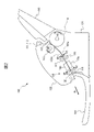
- FIG. 1 is a perspective view showing a medium conveying device 100 configured as an image scanner.
- the medium conveying device 100 conveys a medium, which is an original, and captures an image.
- the medium may be paper, thin paper, cardboard, card, passport, or the like.
- the card includes an ID-1 ID card defined by ISO (International Organization for Standardization)/IEC (International Electrotechnical Commission) 7810. Cards also include ID cards with embossments as specified in ISO/IEC 7811-1.
- the media transport device 100 may be a facsimile machine, a copier, a multifunction peripheral (MFP), or the like. Note that the medium to be conveyed may be an object to be printed instead of a document, and the medium conveying device 100 may be a printer or the like.
- the medium transport device 100 includes a lower housing 101, an upper housing 102, a mounting table 103, a discharge table 104, an operation device 105, a display device 106, and the like.
- arrow A1 indicates the medium transport direction.
- upstream refers to upstream in the medium transport direction A1
- downstream refers to downstream in the medium transport direction A1.
- an arrow A2 indicates the width direction orthogonal to the medium conveying direction.
- the upper housing 102 is arranged to cover the upper surface of the medium transporting device 100, and is engaged with the lower housing 101 by a hinge so that it can be opened and closed when the medium is clogged, when cleaning the inside of the medium transporting device 100, or the like.
- the mounting table 103 engages with the lower housing 101 and mounts a medium to be fed and transported.
- the mounting table 103 is inclined downward from the upstream side to the downstream side.
- the medium conveying device 100 can favorably convey the medium using the weight of the medium.
- the ejection table 104 engages with the upper housing 102 and places the ejected medium. Note that the discharge table 104 may be engaged with the lower housing 101 .
- the operation device 105 has an input device such as a button and an interface circuit that acquires signals from the input device, receives an input operation by the user, and outputs an operation signal according to the user's input operation.
- the display device 106 has a display including liquid crystal, organic EL (Electro-Luminescence), etc. and an interface circuit for outputting image data to the display, and displays the image data on the display.
- FIG. 2 is a diagram for explaining the transport path inside the medium transport device 100.
- FIG. 2 is a diagram for explaining the transport path inside the medium transport device 100.
- the transport path inside the medium transport device 100 includes a load sensor 111, a medium size sensor 112, a medium sensor 113, a feed roller 114, a separation roller 115, a first transport roller 116, a second transport roller 117, an imaging device 118, a 1 discharge roller 119, second discharge roller 120, and the like.
- each of the feed roller 114, the separation roller 115, the first conveying roller 116, the second conveying roller 117, the first discharge roller 119 and/or the second discharge roller 120 is not limited to one, and may be plural. good. In that case, the plurality of feeding rollers 114, separation rollers 115, first conveying rollers 116, second conveying rollers 117, first discharge rollers 119 and/or second discharge rollers 120 are spaced apart in the width direction A2. placed side by side.
- the upper surface of the lower housing 101 forms the lower guide 101a of the medium transport path
- the lower surface of the upper housing 102 forms the upper guide 102a of the medium transport path.
- the loading amount sensor 111 is a sensor for detecting the loading amount of media placed on the loading table 103 and is arranged upstream of the feed roller 114 and the separation roller 115 .
- the payload sensor 111 is an infrared proximity distance sensor that measures the distance to an object present at a facing position based on, for example, the time difference between irradiation and reflection of infrared rays.
- the payload sensor 111 has a light emitter and a light receiver provided on the upper housing 102 .
- the light emitter is an LED (Light Emitting Diode) or the like, and emits light (infrared rays) toward the mounting table 103 .
- the light receiver is a photodiode or the like, receives the light emitted by the light emitter and reflected by the mounting table 103 or the medium mounted on the mounting table 103, and outputs an electric signal corresponding to the received light. Generates and outputs a payload signal.
- the load signal indicates, for example, the time from when the light emitter emits light until when the light receiver receives the light. Based on the load signal, the medium transport device 100 detects the height of the medium placed on the placement table 103 as the load of the medium.
- the load sensor 111 may be a movement sensor (actuator).
- the movement amount sensor includes a contact member that contacts the top surface of the uppermost medium among the media mounted on the mounting table 103 and is movable upward by the medium that contacts the medium. Detect quantity.
- the load amount sensor 111 generates and outputs a load amount signal, which is an electric signal corresponding to the detected movement amount.
- the medium transport device 100 detects the height of the medium placed on the mounting table 103 as the load amount of the medium based on the load amount signal.
- the load amount sensor 111 may be a weight sensor for detecting the weight of the medium placed on the placement table 103 .
- the weight sensor has a pressure-sensitive sheet (conductive film sheet) arranged between the lower housing 101 and the mounting table 103, and the load amount sensor 111 responds to the pressure sensed by the pressure-sensitive sheet. It generates and outputs a load amount signal, which is an electrical signal.
- a load amount signal which is an electrical signal.
- the medium transport device 100 Based on the load signal, the medium transport device 100 detects the weight of the medium placed on the placement table 103 as the load of the medium.
- the medium size sensor 112 is a sensor for detecting the size of the medium, and is arranged upstream from the feed roller 114 and separation roller 115 .
- the medium size sensor 112 includes, for example, a plurality of optical sensors arranged side by side at intervals in the width direction A2 and detecting the medium at each arranged position.
- Each optical sensor includes a light emitter and a light receiver provided in one of lower housing 101 or upper housing 102 and the other housing of lower housing 101 or upper housing 102. , a light guide provided opposite the light emitter and the light receiver.
- the light emitter is an LED or the like, and emits light toward the light guide tube.
- the light receiver is a photodiode or the like, and receives light emitted by the light emitter and guided by the light guide tube.
- the medium size sensor 112 generates and outputs a medium size signal indicating whether or not a medium exists at a position facing each light emitter and light receiver based on the intensity of light received by each light receiver.
- a reflecting member such as a mirror may be used instead of the light guide tube. Also, the light emitter and the light receiver may be provided facing each other across the medium transport path.
- the medium size sensors 112 are arranged side by side at intervals in the width direction A2, and measure the distance to an object existing at the opposite position based on the time difference between irradiation and reflection of the infrared rays at each arranged position.
- a proximity sensor may also be used.
- the medium size sensor 112 has a light emitter and a light receiver provided on the upper housing 102 .
- the light emitter is an LED or the like, and emits light (infrared rays) toward the mounting table 103 .
- the light receiver is a photodiode or the like, and receives light emitted by the light emitter and reflected by the mounting table 103 or the medium mounted on the mounting table 103 .
- the medium size sensor 112 determines whether or not a medium exists at a position facing each light emitter and light receiver based on the time from when each light emitter emits light until each light receiver receives light. It generates and outputs a medium size signal to indicate.
- the medium size sensors 112 are arranged side by side at intervals in the width direction A2, and at each arranged position, a predetermined current flows when the medium is in contact or when the medium is not in contact.
- a contact detection sensor may be used.
- the medium size sensor 112 generates and outputs a medium size signal indicating whether or not a medium exists at a position facing each contact detection sensor depending on whether or not the medium is in contact with each contact detection sensor.
- the medium size sensor 112 may have an imaging sensor equipped with two-dimensionally arranged CMOS (Complementary Metal Oxide Semiconductor) or CCD (Charge Coupled Device) imaging elements.
- the medium size sensor 112 is arranged so as to be able to capture an image of the entire medium mounted on the mounting table 103 .
- the medium size sensor 112 further includes a lens that forms an image on the image sensor, and an A/D converter that amplifies the electrical signal output from the image sensor and performs analog/digital (A/D) conversion. .
- the medium size sensor 112 captures an image of the medium mounted on the mounting table 103, generates an image signal, and outputs the image signal as a medium size signal.
- the medium sensor 113 is arranged upstream from the feed roller 114 and the separation roller 115 .
- the medium sensor 113 has a contact detection sensor and detects whether or not a medium is mounted on the mounting table 103 .
- the medium sensor 113 generates and outputs a medium signal whose signal value changes depending on whether or not the medium is mounted on the mounting table 103 .
- the medium sensor 113 is not limited to a contact detection sensor, and any other sensor capable of detecting the presence or absence of a medium, such as a light detection sensor, may be used as the medium sensor 113 .
- the feeding roller 114 is provided in the lower housing 101, and separates and feeds the medium placed on the placing table 103 in order from the bottom.
- the separation roller 115 is a so-called brake roller or retard roller, which is arranged in the upper housing 102, i.e., above the feeding roller 114, facing the feeding roller 114, and rotates in the direction opposite to the medium feeding direction. .
- a first conveying roller 116 and a second conveying roller 117 are arranged on the downstream side of the feeding roller 114 so as to face each other, and convey the medium fed by the feeding roller 114 and the separation roller 115 to the imaging device 118 . do.
- the first transport rollers 116 are provided in the lower housing 101
- the second transport rollers 117 are provided in the upper housing 102 above the first transport rollers 116 .
- the imaging device 118 is arranged downstream from the first transport roller 116 and the second transport roller 117 and captures an image of the medium transported by the first transport roller 116 and the second transport roller 117 .
- the image pickup device 118 includes a first image pickup device 118a and a second image pickup device 118b arranged to face each other across the medium transport path.
- the first imaging device 118a has a linear optical system type CIS (Contact Image Sensor) line sensor having CMOS imaging elements linearly arranged in the main scanning direction. Also, the first imaging device 118a has a lens that forms an image on the imaging device, and an A/D converter that amplifies an electrical signal output from the imaging device and performs analog/digital (A/D) conversion.
- the first imaging device 118a captures an image of the surface of the medium being conveyed, generates an input image, and outputs the input image, under the control of a processing circuit, which will be described later.
- the second imaging device 118b has a linear optical system type CIS line sensor having CMOS imaging elements linearly arranged in the main scanning direction. Also, the second imaging device 118b has a lens that forms an image on the imaging device, and an A/D converter that amplifies an electrical signal output from the imaging device and performs analog/digital (A/D) conversion.
- the second image capturing device 118b captures an image of the back surface of the medium being conveyed, generates an input image, and outputs the input image, under the control of a processing circuit, which will be described later.
- the medium conveying device 100 may have only one of the first imaging device 118a and the second imaging device 118b and read only one side of the medium.
- a line sensor of the same-magnification optical system type CIS having the CMOS image pickup device instead of the line sensor of the same-magnification optical system type CIS having the CMOS image pickup device, a line sensor of the same-magnification optical system type CIS having the CCD image pickup device may be used. Also, a reduction optics type line sensor having a CMOS or CCD imaging device may be used.
- the first discharge roller 119 and the second discharge roller 120 are arranged on the downstream side of the imaging device 118 so as to face each other.
- the loaded medium is ejected onto the ejection table 104 .
- the first discharge rollers 119 are provided in the lower housing 101
- the second discharge rollers 120 are provided in the upper housing 102 above the first discharge rollers 119 .
- the medium placed on the mounting table 103 is moved in the medium transport direction A1 between the lower guide 101a and the upper guide 102a by rotating the feed roller 114 in the direction of the arrow A3 in FIG. 2, that is, the medium feed direction. transported towards.
- the medium conveying device 100 has, as feeding modes, a separation mode in which the medium is separated and fed, and a non-separation mode in which the medium is fed without being separated.
- the feeding mode is set by the user using the operation device 105 or the information processing device that communicates with the medium conveying device 100 .
- the separation roller 115 rotates in the direction of the arrow A4, that is, in the direction opposite to the medium feeding direction, during medium feeding.
- the medium is fed between the first transport roller 116 and the second transport roller 117 while being guided by the lower guide 101a and the upper guide 102a.
- the medium is fed between the first imaging device 118a and the second imaging device 118b by rotating the first transport roller 116 and the second transport roller 117 in the directions of arrows A5 and A6, respectively.
- the medium read by the imaging device 118 is ejected onto the ejection table 104 by rotating the first ejection roller 119 and the second ejection roller 120 in the directions of arrows A7 and A8, respectively.
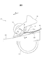
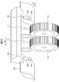
- FIG. 3 and 4 are schematic diagrams for explaining the feeding mechanism 121 of the medium conveying device 100.
- FIG. 3 is a schematic diagram of the feeding mechanism 121 viewed from the upstream side
- FIG. 4 is a schematic diagram of the feeding mechanism 121 viewed from the side (from the width direction A2).
- the medium conveying device 100 includes, as a feeding mechanism 121, a feeding roller 114 and a separation roller 115, as well as a guide member 122, a separation roller cover 123, a bottom surface guide 124, and a first guide. 125, a second guide 126, and the like.
- the medium conveying device 100 has two feed rollers 114 and two separation rollers 115 .
- the guide member 122 is a plate-like member, is provided on the upper surface of the lower housing 101 so as to form a medium transport surface 122a, and forms part of the lower guide 101a.
- the guide member 122 has an opening in the center in the width direction A2 orthogonal to the medium conveying direction, and the feeding roller 114 is arranged in the opening.
- the separation roller cover 123 is an example of a support section, and covers and supports the separation roller 115 .
- the separation roller cover 123 is attached to the upper housing 102 via an elastic member (not shown) such as a spring or rubber, and is biased downward by the elastic member. As a result, the separation roller cover 123 applies an urging force to the separation roller 115 so that the separation roller 115 presses the feeding roller 114 .
- the lower surface guide 124 is a set guide for setting the medium.
- the lower surface guide 124 is arranged at a position overlapping the feeding roller 114 and the separation roller 115 when viewed in the width direction A2, that is, at a position overlapping the feeding roller 114 and the separation roller 115 in the medium conveying direction A1.
- the lower surface guide 124 is provided on the lower housing 101 so as to be able to swing (rotate) downward (in the direction of arrow A9 in FIG. 4) according to a driving force from a motor (not shown).
- the lower surface guide 124 is arranged at a first position (arranged position shown in FIG.
- the lower surface guide 124 is formed of a member with high slidability (having a small frictional force against the medium) such as a plastic member.
- the lower guide 124 is formed of a member that has a smaller frictional force with the PPC paper than the frictional force between two PPC papers.
- the outer peripheral surface of the feed roller 114 is formed of a rubber member or the like having a large frictional force with respect to the medium so that the feed roller 114 can feed the medium satisfactorily. Therefore, the frictional force between the lowest medium among the media M1 placed on the platform 103 and the feed roller 114 is greater than the frictional force between the media M1.
- the mounting table 103 is inclined so that the downstream side faces downward so that the medium can be easily conveyed by its own weight. Therefore, if the medium transport device does not have a bottom surface guide, the leading edge of the medium placed on the upper side will precede the leading edge of the medium placed on the lowest side before the medium is fed ( downstream), and multi-feeding of media tends to occur during feeding of media.
- the medium transport device 100 can suppress the occurrence of double feeding of media.
- the first guide 125 is a flap and a stopper for preventing the medium from entering the nip portion between the feed roller 114 and the separation roller 115 before the medium is fed.
- the first guide 125 is arranged at a position facing the bottom surface guide 124 in the medium transport direction A1.
- the first guide 125 is provided in a later-described feeding arm housed in the separation roller cover 123 so as to be capable of swinging (rotating) downstream (in the direction of arrow A10 in FIG. 4).
- a member presses toward the upstream side (opposite direction of arrow A10).
- the first guide 125 engages with the bottom surface guide 124 arranged at the first position before the medium is fed, and limits the contact between the leading edge of the medium M1 placed on the placing table 103 and the separation roller 115 . That is, the first guide 125 prevents the medium from entering the nip portion between the feed roller 114 and the separation roller 115 before the medium is fed.
- the first guide 125 is provided to interlock with the feeding arm, and when the first guide 125 is engaged with the bottom guide 124, the feeding arm is supported by the first guide 125 and the bottom guide 124 to feed the feed arm. Downward movement of the arm is blocked. Therefore, in FIGS. 3 and 4, the feeding arm is housed inside the separation roller cover 123 .
- the first guide 125 is arranged upstream of the upstream end of the separation roller 115 and near the separation roller 115 in the medium conveyance direction A1 before the medium is fed. Therefore, the position (height) of the medium that abuts against the first guide 125 and stops before the medium is fed, and the position (height) of the medium that abuts against the separation roller 115 and stops immediately after the start of medium feeding. is small, and the magnitude of the potential energy generated by the difference in height is small. Therefore, immediately after the start of feeding the medium, the medium abuts against the separation roller 115 forcefully, the separation roller 115 is pushed up by the medium, and the reduction in the force for separating the medium is suppressed. Therefore, the medium conveying device 100 can suppress the occurrence of double feeding of media and can separate a plurality of media satisfactorily.
- the first guide 125 engages with the lower surface guide 124 arranged at the first position so as to be inclined with respect to the lower surface guide 124 . That is, the angle ⁇ 1 between the contact surface 125a of the first guide 125 that contacts the leading edge of the medium M1 and the support surface 124a of the lower surface guide 124 is set to be larger than 0° and smaller than 90°. In particular, the angle ⁇ 1 is set to be greater than 45° and less than 90°.
- the leading edge of the lower media is arranged downstream before the media are fed. This makes it easier for the medium to enter the nip portion between the feed roller 114 and the separation roller 115 . Therefore, the medium conveying device 100 can smoothly feed the medium at the start of medium feeding, and can reduce the time required for medium feeding.
- a plurality of sets of the first guides 125 and the lower surface guides 124 are arranged side by side at intervals in the width direction A2 perpendicular to the medium transport direction. They are arranged at approximately the same position in the direction A1. Also, each set of the first guide 125 and the lower surface guide 124 is arranged with an interval equal to or less than the minimum medium size width supported by the medium transport device 100 (for example, the length of A8 size in the lateral direction) in the width direction A2. be.
- the minimum medium size width supported by the medium transport device 100 for example, the length of A8 size in the lateral direction
- each set of the first guide 125 and the bottom guide 124 may be spaced apart in the width direction A2 larger than the minimum media size width supported by the media transport device 100 .
- the second guide 126 has a contact surface 126a that contacts the leading edge of the medium to be fed.
- the second guide 126 is provided on the separation roller cover 123 so as to protrude from the separation roller cover 123 above the nip portion between the feeding roller 114 and the separation roller 115 .
- the second guide 126 is arranged between the upstream end of the separation roller 115 in the medium conveyance direction A1 and the center O of the separation roller 115 in the medium conveyance direction A1.
- the second guide 126 is arranged outside the first guide 125 and near the separation roller 115 in the width direction A2 perpendicular to the medium conveying direction.
- the inner end of the second guide 126 is arranged within 30 mm from the outer end of the separation roller 115 in the width direction A2.
- the second guide 126 can regulate the central portion of the medium in the width direction A2, and can appropriately stop the medium.
- the second guide 126 can favorably regulate the leading edge of the media when a plurality of small-sized media are collectively placed on the placement table 103 and fed.
- the first guide 125 and/or the second guide 126 may be arranged between the two separation rollers 115 in the width direction A2.
- the second guide 126 is formed on the contact surface 126a so that the coefficient of friction of the first region 126b above the predetermined position is greater than the coefficient of friction of the second region 126c below the predetermined position. That is, the second guide 126 is formed such that the first region 126b and the second region 126c have different surface roughness or have different member friction resistances.
- the predetermined position is set, for example, at the center position between the upper end position and the lower end position of the contact surface 126a. Note that the predetermined position may be set at any position within the contact surface 126a.
- the coefficient of friction of the first region 126b is set to 0.5 or more, for example. For example, an uneven shape is formed in the first region 126b.
- a rubber member may be attached to the first region 126b.
- the coefficient of friction of the second region 126c is set to, for example, less than 0.5 (for example, approximately 0.3).
- the second region 126c is made of, for example, a resin material.
- the second guide 126 makes it easier for the leading end of the medium to be caught in the upper region of the contact surface 126a, and appropriately prevents the medium from entering the downstream side.
- the second guide 126 allows the leading edge of the medium to drop smoothly in the region below the contact surface 126a, and allows the medium to be smoothly guided to the nip portion between the feed roller 114 and the separation roller 115 by the pressure roller, which will be described later. .
- the second guides 126 are arranged side by side at intervals in the width direction A2 orthogonal to the medium conveying direction, and each of the second guides 126 is positioned substantially at the same position in the medium conveying direction A1. placed in Further, the second guides 126 are arranged at intervals equal to or less than the minimum medium size width supported by the medium transport device 100 plus a margin (for example, 40 mm) in the width direction A2.
- a margin for example, 40 mm
- the medium conveying device 100 can prevent the leading edge of the medium from being arranged at an angle, and can prevent the skew of the medium from occurring.
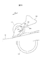
- FIG. 5 is a schematic diagram for explaining the lower surface guide 124 and the first guide 125 during medium feeding.
- FIG. 5 is a schematic side view of the feeding mechanism 121 during medium feeding.
- the feeding mechanism 121 further includes a feeding arm 127.
- the feeding arm 127 is housed inside the separation roller cover 123 so as to be vertically movable with respect to the separation roller cover 123 .
- the feeding arm 127 is attached inside the separation roller cover 123 via an elastic member (not shown) such as a spring or rubber, and is biased downward against the separation roller cover 123 by the elastic member.
- the feeding arm 127 is provided with a pressing roller 127a.
- the pressing roller 127a faces the feed roller 114 and is arranged upstream of the nip portion between the feed roller 114 and the separation roller 115 in the medium transport direction A1.
- the pressing roller 127a presses the medium fed by the feeding roller 114 from above toward the feeding roller 114 side.
- the pressing roller 127 a sandwiches the medium with the feeding roller 114 and applies a conveying force to the medium fed by the feeding roller 114 .
- the medium conveying device 100 can feed the medium satisfactorily.
- the lower surface guide 124 swings downward (in the direction of arrow A9) from the conveying surface 122a of the guide member 122.
- the lower surface guide 124 is arranged at the second position (arrangement position shown in FIG. 5) that allows contact between the lower surface of the medium M1 placed on the mounting table 103 and the feeding roller 114 during medium feeding. It is separated from the lower surface of the medium M1 placed on the placing table 103 .
- the engagement between the first guide 125 and the lower surface guide 124 is released.
- the first guide 125 is pushed by the leading edge of the medium M1 placed on the placing table 103 and swings downstream (in the direction of the arrow A10), and the medium M1 moves between the feed roller 114 and the separation roller. It becomes possible to enter the nip portion of 115 .
- the first guide 125 allows the medium M1 to enter the nip portion between the feed roller 114 and the separation roller 115 when the bottom guide 124 is arranged at the second position.
- the feeding arm 127 since the feeding arm 127 is biased downward by the elastic member, the feeding arm 127 is moved by releasing the engagement between the first guide 125 and the lower surface guide 124. , downward (toward the feeding roller 114).
- the amount of the medium M1 placed on the placement table 103 is sufficiently small. In this case, first, the feed roller 114 contacts the lowest medium among the media M1 placed on the mounting table 103, and then the pressing roller 127a is placed on the mounting table 103. It contacts the uppermost medium among the mediums M1.
- the pressing roller 127a is placed after the feeding roller 114 if the amount of the medium placed on the placing table 103 is less than a predetermined amount. It is provided so as to come into contact with the medium placed on the table 103 .
- the feeding roller 114 When the amount of the medium placed on the mounting table 103 is small, if the feeding roller 114 is started to rotate while the pressure roller 127a is pressing the medium, the leading edge of the medium tends to bend upward, which prevents the medium from jamming. Likely to happen.
- the medium conveying device 100 brings the feeding roller 114 into contact with the medium before the pressing roller 127a to start feeding the medium, thereby moving the leading edge of the medium upward. It is possible to suppress the occurrence of media jams due to bending.
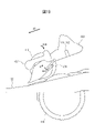
- FIG. 6 is a schematic diagram for explaining the lower surface guide 124 and the first guide 125 when a large amount of media M2 are placed on the placing table 103.
- FIG. FIG. 6 is a schematic side view of the feeding mechanism 121 immediately after the start of medium feeding when a large amount of media M2 are placed on the mounting table 103. As shown in FIG.
- the bottom guide 124 is placed at the second position, the engagement between the first guide 125 and the bottom guide 124 is released, and the feeding arm 127 moves downward.
- the feed arm 127 is lowered before the lower surface guide 124 is lowered. Therefore, before the feeding roller 114 contacts the lowest medium among the media M2 placed on the mounting table 103, the pressure roller 127a is pressed against the medium M2 placed on the mounting table 103. It contacts the medium arranged on the uppermost side.
- the pressing roller 127a moves forward of the feeding roller 114 if the amount of media placed on the placing table 103 is equal to or greater than a predetermined amount. It is provided so as to come into contact with the medium mounted on the mounting table 103 .
- the feeding roller 114 can feed the medium satisfactorily by starting the rotation of the feeding roller 114 while the pressure roller 127a is pressing the medium. can.
- the elastic member applies a larger biasing force to the medium than when the amount of the medium is small.
- the elastic member is a compression spring
- the magnitude of the biasing force is a multiplication value obtained by multiplying the contraction amount of the spring by the spring constant.
- the medium transporting device 100 gives priority to the ability to feed the media, and feeds the media satisfactorily. It is possible to
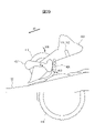
- FIG. 7 is a schematic diagram for explaining the second guide 126 when a large amount of media M3 are mounted on the mounting table 103.
- FIG. FIG. 7 is a schematic side view of the feeding mechanism 121 during medium feeding when a large amount of media M3 are placed on the mounting table 103. As shown in FIG.
- the second guide 126 is designed to move the media. It abuts on the leading end of M3 to block entry of the medium M3 to the downstream side. As a result, the second guide 126 can prevent the separation roller 115 from being lifted (lifted) by the medium M3 and reducing the force for separating the medium.
- the second guide 126 regulates the leading edge of the medium at a position a predetermined distance D above the nip surface N, which is the extended surface of the nip portion between the feeding roller 114 and the separation roller 115, during the medium feeding. do. That is, the second guide 126 is arranged so as not to overlap the feeding roller 114 when viewed from the width direction A2 orthogonal to the medium conveying direction. Thereby, the second guide 126 contacts only the upper medium among the mediums M3 placed on the placing table 103 . Therefore, the second guide 126 allows the medium placed on the lower side to enter the nip portion between the feed roller 114 and the separation roller 115, while preventing the medium placed on the upper side from entering the downstream side. Restrict. Since only the media arranged on the lower side contact the separation roller 115, the second guide 126 can prevent the separation roller 115 from rising (floating) and reducing the force for separating the media.
- the ID card has high rigidity compared to paper, etc., and does not deform. Therefore, when the medium conveying device 100 attempts to separate a plurality of ID cards at the position of the second guide 126, the conveying load on the feeding roller 114 increases. Therefore, in order to separate a plurality of ID cards at the position of the second guide 126 , the medium conveying device 100 needs to increase the force with which the separation roller 115 presses the feeding roller 114 . However, if the force with which the separation roller 115 presses the feeding roller 114 is too large, it becomes difficult for the medium conveying device 100 to separate media such as paper.
- each ID card is appropriately separated at the nip portion between the feed roller 114 and the separation roller 115. Therefore, the medium conveying device 100 can handle the ID cards and It is possible to feed both sheets while separating them satisfactorily.
- the size of the ID card is small, and there is a high possibility that the side guide will not be set when the ID card is fed. Furthermore, since the frictional force between ID cards is small, when a plurality of ID cards are separated at the position of the second guide 126, the ID cards remaining at the position of the second guide 126 are tilted, causing the skew of the medium. more likely to. Since the second guide 126 is provided so that a plurality of ID cards can pass through, each ID card is properly separated at the nip portion between the feeding roller 114 and the separation roller 115, the medium conveying device 100 can prevent the medium from skewing. It is possible to suppress the occurrence of
- the predetermined distance D is preferably set to a length of 7 mm or less.
- the separation roller cover 123 has a guide surface 123a formed on the upstream side of the upstream end of the separation roller 115 in the medium conveying direction A1.
- An extended surface E obtained by extending the guide surface 123 a is arranged so as to pass through the central portion O of the separation roller 115 . That is, the guide surface 123a is formed at the same position as the center O of the separation roller 115 in the height direction.
- the feeding force required to cause it to increase is increased.
- the medium contacts a position higher than the central portion O on the outer peripheral surface of the separation roller 115 there is a possibility that the medium is not properly fed, causing a feeding abnormality.
- the medium transporting device 100 can limit the amount of media entering the position where the separation roller 115 contacts the separation roller cover 123 .
- the medium conveying device 100 can prevent the medium from contacting a position higher than the central portion O on the outer peripheral surface of the separation roller 115 . Therefore, it is possible to suppress the occurrence of medium feeding abnormality.
- the extended surface E obtained by extending the guide surface 123a may be arranged so as to be positioned below the central portion O of the separation roller 115 . That is, the guide surface 123a may be formed below the central portion O of the separation roller 115 in the height direction. By arranging the guide surface 123a at a position lower than the center O of the separation roller 115, the medium conveying device 100 can feed the medium with a sufficiently small feeding force.
- FIG. 8 is a schematic diagram for explaining the second guide 126 when the medium M4 having a curled tip is placed on the placing table 103.
- FIG. 8 is a schematic side view of the feeding mechanism 121 during medium feeding when the medium M4 having a curled front end is placed on the placing table 103.
- the first guide 125 and the feeding arm 127 are omitted for better visibility.
- the separation roller 115 rotates in the direction A4 opposite to the medium feeding direction, and the feed roller 114 Push back any media that is not in contact with the
- the separation roller 115 moves to the feed roller 114. , and rotates in the medium feeding direction A9.
- the second guide 126 is arranged upstream of the upstream end of the separation roller 115 in the medium conveying direction A1
- the entry of the leading edge of the curled medium M4 into the nip portion between the feeding roller 114 and the separation roller 115 is It is blocked by the second guide 126 . Therefore, the medium M4 does not enter the nip portion between the feed roller 114 and the separation roller 115, and a medium jam occurs.
- the second guide 126 is arranged downstream of the upstream end of the separation roller 115 in the medium conveying direction A1.
- the leading edge of the curled medium M4 contacts the separation roller 115 without being blocked by the second guide 126, and is guided by the separation roller 115 rotating in the medium feeding direction A9. enter in between. Therefore, the medium conveying device 100 can suppress jamming of media with curled leading edges.
- FIG. 9 is a schematic diagram for explaining the inclination of the second guide 126.
- FIG. FIG. 9 is a schematic diagram of the second guide 126 viewed from the side.
- the first guide 125 and the feeding arm 127 are omitted for better visibility.
- the second guide 126 is arranged such that the contact surface 126 a that contacts the leading edge of the medium is inclined with respect to the nip surface N between the feeding roller 114 and the separation roller 115 . That is, the angle ⁇ 2 formed by the contact surface 126a of the second guide 126 and the nip surface N is set to be larger than 0° and smaller than 90°. In particular, the angle ⁇ 2 is set to be greater than 45° and less than 90°. As a result, of the media in contact with the contact surface 126a, the leading edge of the lower media is arranged on the downstream side. It becomes easier to enter the nip portion of the separation roller 115 . Therefore, the medium conveying device 100 can smoothly feed the medium at the start of medium feeding, and can reduce the time required for medium feeding.
- the separation roller 115 is pulled by the feeding roller 114 at the nip portion with the feeding roller 114 .
- the downstream end of the nip portion of the separation roller 115 swells, and the upstream end of the nip portion of the separation roller 115 dents accordingly. Therefore, as shown in FIG. 9, a recess 115a is formed in the upstream and lower portion of the outer peripheral surface of the separation roller 115.
- the abutment surface 126a of the second guide 126 is inclined with respect to the nip surface N so as to be arranged substantially parallel to the recess 115a. abut evenly on the As a result, the second guide 126 can evenly apply a load to the media in contact with each other and appropriately align the leading edges of the media. As a result, the medium conveying device 100 can feed the medium more satisfactorily.
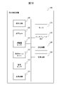
- FIG. 10 is a block diagram showing a schematic configuration of the medium conveying device 100. As shown in FIG.
- the medium transport device 100 further includes a motor 131, an interface device 132, a storage device 140, a processing circuit 150, etc., in addition to the configuration described above.
- the motor 131 has one or a plurality of motors, and operates the feed roller 114, the separation roller 115, the first conveying roller 116, the second conveying roller 117, the first discharge roller 119 and the first discharge roller 119 according to a control signal from the processing circuit 150. 2
- the discharge roller 120 is rotated to convey the medium.
- One of the first transport roller 116 and the second transport roller 117 may be a driven roller that rotates following the other roller.
- one of the first discharge roller 119 and the second discharge roller 120 may be a driven roller that rotates following the other roller.
- the motor 131 moves the lower surface guide 124 between the first position and the second position according to control signals from the processing circuit 150 .
- the interface device 132 has an interface circuit conforming to a serial bus such as USB, for example, and is electrically connected to an information processing device (for example, personal computer, personal digital assistant, etc.) (not shown) to receive an input image and various information. Send and receive.
- an information processing device for example, personal computer, personal digital assistant, etc.
- a communication unit having an antenna for transmitting and receiving wireless signals and a wireless communication interface device for transmitting and receiving signals through a wireless communication line according to a predetermined communication protocol may be used.
- the predetermined communication protocol is, for example, a wireless LAN (Local Area Network).
- the communication unit may have a wired communication interface device for transmitting and receiving signals through a wired communication line according to a communication protocol such as a wired LAN.
- the storage device 140 includes memory devices such as RAM (Random Access Memory) and ROM (Read Only Memory), fixed disk devices such as hard disks, or portable storage devices such as flexible disks and optical disks.
- the storage device 140 also stores computer programs, databases, tables, and the like used for various processes of the medium transport device 100 .
- the computer program may be installed in the storage device 140 from a computer-readable portable recording medium using a known setup program or the like.
- the portable recording medium is, for example, a CD-ROM (compact disc read only memory), a DVD-ROM (digital versatile disc read only memory), or the like.
- the processing circuit 150 operates based on a program stored in the storage device 140 in advance.
- the processing circuit is, for example, a CPU (Central Processing Unit).
- a DSP digital signal processor
- LSI large scale integration
- ASIC Application Specific Integrated Circuit
- FPGA Field-Programmable Gate Array
- the processing circuit 150 is connected to the operation device 105, the display device 106, the load amount sensor 111, the medium size sensor 112, the medium sensor 113, the imaging device 118, the motor 131, the interface device 132, the storage device 140, etc., and controls these units. Control. Based on the medium signal received from the medium sensor 113 , the processing circuit 150 performs drive control of the motor 131 , imaging control of the imaging device 118 , acquires an input image from the imaging device 118 , and outputs information via the interface device 132 . Send to processor.
- FIG. 11 is a diagram showing a schematic configuration of the storage device 140 and the processing circuit 150. As shown in FIG.
- the storage device 140 stores a control program 141, an image acquisition program 142, a detection program 143, and the like. Each of these programs is a functional module implemented by software running on a processor.
- the processing circuit 150 reads each program stored in the storage device 140 and operates according to each read program. Thereby, the processing circuit 150 functions as a control section 151 , an image acquisition section 152 and a detection section 153 .
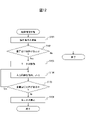
- FIG. 12 is a flow chart showing an example of the operation of the medium reading process of the medium conveying device 100.
- control unit 151 receives an instruction to read a medium from the operation device 105 or the interface device 132 when a user inputs an instruction to read the medium using the operation device 105 or the information processing device. (step S101).
- control unit 151 acquires a medium signal from the medium sensor 113, and determines whether or not a medium is placed on the placing table 103 based on the acquired medium signal (step S102). If no medium is placed on the placing table 103, the control unit 151 terminates the series of steps.
- the control section 151 drives the motor 131 to move the lower surface guide 124 from the first position to the second position. Further, the control unit 151 drives the motor 131 to rotate the feed roller 114, the separation roller 115, the first transport roller 116, the second transport roller 117, the first discharge roller 119 and/or the second discharge roller 120. to convey the medium (step S103).
- the image acquisition unit 152 causes the imaging device 118 to image the medium, acquires an input image from the imaging device 118, and transmits the acquired input image to the information processing device via the interface device 132, thereby outputting the image. (step S104).
- control unit 151 determines whether or not the medium remains on the mounting table 103 (step S105). When the medium remains on the mounting table 103, the control unit 151 returns the process to step S104 and repeats the processes of steps S104 and S105.
- control unit 151 controls the feeding roller 114, the separating roller 115, the first conveying roller 116, the second conveying roller 117, the first discharge roller 119 and/or the second discharge.
- Motor 131 is controlled to stop roller 120 .
- control unit 151 controls the motor 131 so as to move the lower surface guide 124 from the second position to the first position (step S106), and ends the series of steps.
- the medium transport device 100 has the first guide 125 that limits the contact between the leading edge of the medium and the separation roller 115 before feeding the medium.
- the medium conveying device 100 includes a second guide 126 arranged downstream of the upstream end of the separation roller 115 and regulating the leading edge of the medium at a predetermined distance above the nip portion between the feeding roller 114 and the separation roller 115 . have.
- the medium conveying device 100 guides only an appropriate amount of media out of the media restricted by the first guide 125 to the nip portion, and suppresses other media from pressing the separation roller 115 .
- the medium conveying device 100 can prevent the separating roller 115 from rising (floating) and reducing the force for separating the medium.
- the medium conveying device 100 can separate a plurality of media satisfactorily, and can suppress the occurrence of double feeding of media.
- the medium conveying device 100 can prevent the second guide 126 from preventing the medium with the curled leading edge from entering the nip portion between the feed roller 114 and the separation roller 115 . Therefore, the medium conveying device 100 can feed the medium satisfactorily.
- the medium conveying device 100 regulates the leading edge of the medium at a predetermined distance above the nip portion between the feed roller 114 and the separation roller 115 , so that regardless of the amount of the medium placed on the platform 103 , the medium can be transported. It is now possible to suppress the occurrence of double feeding and to feed media stably.
- the medium transport device 100 can feed various types of media such as normal paper, thin paper whose tip tends to curl, cards, thick paper, and passports.
- the medium transport device 100 can stably feed media regardless of the number or types of media to be fed. Therefore, the user does not need to change the settings of the medium transporting device 100 according to the number or type of media to be fed, and the medium transporting device 100 can improve user convenience. . Along with this, the medium transport device 100 can suppress the occurrence of setting errors by the user, and can suppress the occurrence of malfunctions due to setting errors. In addition, the medium conveying device 100 does not need to provide special parts for feeding a special type of medium or a large amount of media, and it is possible to suppress an increase in device cost. It has become possible.
- FIGS. 13 and 14 are schematic diagrams for explaining the separation roller cover 223 and the second guide 226 in the medium conveying device according to another embodiment.
- FIG. 13 is a schematic diagram of the separation roller cover 223 viewed from the upstream side.
- FIG. 14 is a schematic diagram of the separation roller cover 223 viewed from the side.
- the display of the guide member 122 is omitted in order to improve visibility.
- the medium conveying device has a separation roller cover 223 and second guides 226 instead of the separation roller cover 123 and second guides 126 .
- the separation roller cover 223 and the second guide 226 have the same configurations as the separation roller cover 123 and the second guide 126.
- the second guide 226 has a fixed portion 226a and a moving portion 226b.
- the fixed portion 226 a is provided so as to be fixed to the separation roller cover 223 .
- the fixing portion 226a is provided above the nip surface N, which is an extension surface of the nip portion between the feeding roller 114 and the separation roller 115, by a predetermined distance D.
- the moving portion 226b is provided between the fixed portion 226a and the nip portion between the feed roller 114 and the separation roller 115 so as to be movable by the leading edge of the medium to be fed.
- the moving part 226b is provided at the lower end of the fixed part 226a so as to be able to swing (rotate) downstream (in the direction of arrow A11 in FIG. 14), and is moved upstream (rotatingly) by an elastic member (not shown) such as a torsion coil spring. (opposite direction of arrow A11).
- each medium is applied with a downstream force by the feed roller 114 and an upstream force by the separation roller 115.
- the pressing force applied to the moving portion 226b by the elastic member is smaller than the downstream force applied to the medium in contact with the feed roller 114 and is applied to the medium not in contact with the feed roller 114 toward the downstream side. set to be greater than the force.
- the second guide 226 can satisfactorily guide the media to be fed (including cards, etc.) to the nip portion between the feed roller 114 and the separation roller 115, while suppressing the occurrence of double feeding of the media.
- the medium conveying device can feed the medium satisfactorily even when the second guide 226 has the fixed portion 226a and the moving portion 226b.
- FIGS. 15 and 16 are schematic diagrams for explaining the separation roller cover 323 and the second guide 326 in the medium conveying device according to still another embodiment.
- FIG. 15 is a schematic diagram of the separation roller cover 323 viewed from the upstream side.
- FIG. 16 is a schematic diagram of the separation roller cover 323 viewed from the side.
- the display of the guide member 122 is omitted in order to improve visibility.
- 15 and 16 show the second guide 326 before medium feeding (initial state).
- the medium conveying device has a separation roller cover 323 and second guides 326 instead of the separation roller cover 123 and second guides 126 .
- the separation roller cover 323 and the second guide 326 have the same configurations as the separation roller cover 123 and the second guide 126.
- the second guide 326 has a shaft 326a, a contact portion 326b and an arm 326c.
- the second guide 326 has two contact portions 326b and two arms 326c.
- the shaft 326a is provided on the separation roller cover 323 so as to be rotatable around a rotation axis extending in the width direction A2, and is directed upstream (opposite direction of arrow A12) by an elastic member (not shown) such as a torsion coil spring. is pressed down.
- the abutment portion 326b has a first abutment surface that abuts against the leading edge of the medium being fed, and is provided on the shaft 326a so as to be rotatable (swingable) as the shaft 326a rotates.
- the first contact surface is arranged at the non-contact position (placement position shown in FIGS. 15 and 16) where it does not contact the leading edge of the medium.
- the contact portion 326b is arranged outside the first guide 125 and near the separation roller 115 in the width direction A2 orthogonal to the medium conveying direction. Each contact portion 326b is arranged at substantially the same position in the medium transport direction A1. Also, the contact portions 326b are arranged at intervals equal to or less than the minimum medium size width supported by the medium transport device 100 plus a margin in the width direction A2.
- the arm 326c has a second contact surface that contacts the upper surface of the medium being fed, and is provided on the shaft 326a so as to rotate the shaft 326a as the arm 326c moves (swings).
- the arm 326c is arranged outside the contact portion 326b in the width direction A2 orthogonal to the medium transport direction.
- Each arm 326c has a distance greater than the longitudinal length of an ID-1 ID card (85.6 mm) defined by ISO/IEC7810 or the longitudinal length of a folded passport (125 mm). are placed in an empty space.
- Each arm 326c is arranged at substantially the same position in the medium transport direction A1.
- FIGS. 17 and 18 are schematic diagrams for explaining the second guide 326 with the contact portion 326b set.
- FIG. 17 is a schematic diagram of the separation roller cover 323 viewed from the upstream side.
- FIG. 18 is a schematic diagram of the separation roller cover 323 viewed from the side.
- the display of the guide member 122 is omitted in order to improve visibility.
- the contact portion 326b set at the contact position is provided above the nip portion between the feed roller 114 and the separation roller 115 so as not to overlap the feed roller 114 when viewed from the width direction A2 orthogonal to the medium conveying direction. placed in The contact portion 326b set at the contact position is arranged between the upstream end of the separation roller 115 in the medium conveyance direction A1 and the central portion O of the separation roller 115 in the medium conveyance direction A1.
- the second guide 326 is provided so as to be movable by the medium when the height of the medium in contact with the separation roller 115 is equal to or higher than a predetermined height. Accordingly, when a medium group having a width longer than the distance between the two arms 326c and a height that contacts the arms 326c is placed on the mounting table 103, the second guide 326 can move the medium group. It abuts on the tip to prevent the media group from entering the downstream side. Therefore, the second guide 326 can prevent the separation roller 115 from rising (lifting) due to the medium group and reducing the force for separating the medium.
- the arms 326c do not contact the medium, so the contact portion 326b is moved to the non-contact position. placed in Therefore, the abutting portion 326b can feed the medium well without blocking the feeding of the thick medium such as an ID card or a passport.
- the medium conveying device can feed the medium satisfactorily even when the second guide 326 is provided so as to be movable according to the height of the medium.
- FIG. 19 is a schematic diagram for explaining the separation roller cover 423 and the second guide 426 in the medium conveying device according to still another embodiment.
- FIG. 19 is a schematic diagram of the separation roller cover 423 viewed from the side. In FIG. 19, the display of the guide member 122 is omitted in order to improve visibility.
- FIG. 19 shows the second guide 426 before medium feeding (initial state).
- the medium conveying device has a separation roller cover 423, a second guide 426 and a cam 427 instead of the separation roller cover 123 and the second guide 126.
- the separation roller cover 423 and the second guide 426 have the same configurations as the separation roller cover 123 and the second guide 126.
- the second guide 426 is provided on the separation roller cover 423 so as to be able to swing (rotate) upstream (in the direction of arrow A13 in FIG. 19), and is moved downstream by an elastic member (not shown) such as a torsion coil spring. side (opposite direction of arrow A13).
- an elastic member such as a torsion coil spring.
- the second guide 426 is arranged at the non-contact position (placement position shown in FIG. 19) where it does not come into contact with the leading edge of the medium.
- the cam 427 is provided on the separation roller cover 423 so as to be able to swing (rotate) in the direction of arrow A14 in FIG. Before the medium is fed (initial state), the cam 427 is arranged at a position separated from the second guide 426 .
- FIG. 20 is a schematic diagram for explaining the second guide 426 in the set state.
- FIG. 20 is a schematic diagram of the separation roller cover 423 viewed from the side.
- the display of the guide member 122 is omitted in order to improve visibility.
- the second guide 426 is provided above the nip portion between the feed roller 114 and the separation roller 115, and is arranged so as not to overlap the feed roller 114 when viewed in the width direction A2 orthogonal to the medium conveying direction. be done.
- the second guide 426 set at the contact position is arranged between the upstream end of the separation roller 115 in the medium conveyance direction A1 and the center O of the separation roller 115 in the medium conveyance direction A1.
- the second guide 426 abuts against the leading edge of the medium to prevent the medium from entering the downstream side when arranged at the abutment position, and prevents the medium from being fed when the second guide 426 is arranged at the non-abutment position. To feed a medium without interrupting the feeding.
- FIG. 21 is a flow chart showing an example of the operation of the medium reading process of the medium conveying device having the second guide 426 and cam 427.
- the operation flow described below is executed mainly by the processing circuit 150 in cooperation with each element of the medium conveying device 100 based on a program stored in advance in the storage device 140 .
- the flowchart shown in FIG. 21 is executed instead of the flowchart shown in FIG.
- the processing of steps S201 to S203 and S211 to S213 of the flowchart shown in FIG. 21 is the same as the processing of steps S101 to S103 and S104 to S106 of the flowchart shown in FIG. Only the processing of steps S204 to S210 will be described below.
- the second guide 426 is placed at the non-contact position before the flowchart shown in FIG. 21 is executed, that is, before the medium is fed.
- control unit 151 determines whether the feeding mode is set to the separation mode or the non-separation mode (step S204).
- the control unit 151 drives the motor 131 to place the second guide 426 at the non-contact position (step S205), and the process proceeds to step S211. .
- the control section 151 retracts the second guide 426 when the medium conveying device 100 operates in the non-separation mode.
- the control unit 151 can retract the second guide 426 to feed the booklet satisfactorily. Note that when the second guide 426 has already been arranged at the non-contact position, the control unit 151 moves the process to step S211 without executing any particular process.
- the detection unit 153 receives the load amount signal from the load amount sensor 111, and determines the size of the medium placed on the mounting table 103 based on the received load amount signal.
- a loading amount is detected (step S206).
- the medium transport device 100 stores in the storage device 140 in advance a table showing the relationship between the signal value of the load amount signal and the load amount (height or weight) of the medium.
- the detection unit 153 refers to the table and specifies the loading amount corresponding to the signal value of the received loading amount signal as the loading amount of the media placed on the mounting table 103 .
- control unit 151 determines whether or not the detected load amount is equal to or greater than a predetermined amount (step S207).
- the predetermined amount is set in advance to a loading amount that requires regulation of the media by the second guide 426 .
- control unit 151 drives the motor 131 to place the second guide 426 at the non-contact position (step S205), and the process proceeds to step S211. Note that when the second guide 426 has already been arranged at the non-contact position, the control unit 151 moves the process to step S211 without executing any particular process.
- the detection unit 153 receives a medium size signal from the medium size sensor 112 and detects the size of the medium placed on the placing table 103 based on the received medium size signal. (step S208). If the medium size signal indicates whether or not a medium exists at a position facing each light emitter and light receiver, the detection unit 153 determines which medium exists in the set of light emitters and light receivers at positions facing each other. The arrangement interval between the two outermost sets is detected as the size in the width direction A2 of the medium. When the medium size signal indicates whether or not the medium exists at the position facing each contact detection sensor, the detection unit 153 detects the two outermost sensors among the sensors at which the medium exists at the facing position.
- the detection unit 153 uses a known image processing technique to detect the size of the medium in the medium transport direction A1 and/or the width direction A2 from the image signal.
- the control unit 151 determines whether or not the size of the detected medium is equal to or larger than a predetermined size (step S209).
- the predetermined size is, for example, the longitudinal length (85.6 mm) of an ID-1 ID card defined by ISO/IEC7810, or the longitudinal length (125 mm) of a folded passport plus a margin. set to the same size.
- the control unit 151 determines whether the longer size of the detected sizes of the medium is equal to or larger than a predetermined size. determine whether In this case, the control unit 151 may determine whether the shorter size of the detected medium sizes is equal to or greater than a predetermined size.
- control unit 151 drives the motor 131 to place the second guide 426 at the non-contact position (step S205), and the process proceeds to step S211. Note that when the second guide 426 has already been arranged at the non-contact position, the control unit 151 moves the process to step S211 without executing any particular process.
- control unit 151 drives the motor 131 to place the second guide 426 at the contact position (step S210). Note that when the second guide 426 has already been arranged at the contact position, the control unit 151 moves the process to step S211 without executing any particular process.
- control unit 151 moves the second guide 426 according to the load amount of media placed on the placement table 103 .
- the control unit 151 can set the second guide 426 when the medium stacking amount is large, and retract the second guide 426 when the medium stacking amount is small. Therefore, the control unit 151 satisfactorily separates the media when the stacking amount of the media is large, and prevents jamming of the media with curled ends by the second guide 426 when the stacking amount of the media is small. can be suppressed.
- control unit 151 moves the second guide 426 according to the size of the medium placed on the placing table 103 .
- the control unit 151 retracts the second guide 426 when a medium having a small size and thickness such as a passport or a card is fed, and when general paper or the like is fed.
- the second guide 426 can be set. Therefore, the control unit 151 can satisfactorily feed a small and thick medium such as a passport or a card, and satisfactorily separate ordinary paper and the like.
- control unit 151 causes the second guide 426 to abut when at least one of the load amount is equal to or greater than a predetermined amount and the size of the media is equal to or greater than a predetermined size. can be placed in position. Also, the process of step S204 may be omitted. Further, the processing of steps S206-S207 and/or steps S208-S209 may be omitted.
- the medium conveying device can feed the medium satisfactorily even when the second guide 426 is movable under the control of the control unit 151 .
- FIG. 22 is a diagram showing a schematic configuration of a processing circuit 550 in a medium conveying device according to still another embodiment.
- the processing circuit 550 is used in place of the processing circuit 150 of the medium transport device 100, and performs medium reading processing and the like instead of the processing circuit 150.
- FIG. The processing circuit 550 has a control circuit 551, an image acquisition circuit 552, a detection circuit 553, and the like. Each of these units may be composed of an independent integrated circuit, microprocessor, firmware, or the like.
- the control circuit 551 is an example of a control section and has the same function as the control section 151.
- the control circuit 551 receives an operation signal from the operation device 105 or the interface device 132 , a medium signal from the medium sensor 113 , and detection results of the loaded amount and size of the medium from the detection circuit 553 .
- the control circuit 551 controls the motor 131 based on the received information.
- the image acquisition circuit 552 is an example of an image acquisition section and has the same function as the image acquisition section 152.
- the image acquisition circuit 552 acquires an input image from the imaging device 118 and outputs it to the interface device 132 .
- the detection circuit 553 is an example of a detection section and has the same function as the detection section 153.
- the detection circuit 553 receives the load signal from the load sensor 111 and the medium size signal from the medium size sensor 112 .
- the detection circuit 553 detects the loaded amount and size of the medium based on each received signal, and outputs the detection result to the control circuit 551 .
- the medium conveying device can feed the medium satisfactorily even when the processing circuit 550 is used.
Landscapes
- Engineering & Computer Science (AREA)
- Mechanical Engineering (AREA)
- Sheets, Magazines, And Separation Thereof (AREA)
- Controlling Sheets Or Webs (AREA)
Priority Applications (5)
| Application Number | Priority Date | Filing Date | Title |
|---|---|---|---|
| US18/575,714 US20240308797A1 (en) | 2021-07-14 | 2021-07-14 | Medium conveyance device |
| PCT/JP2021/026494 WO2023286214A1 (ja) | 2021-07-14 | 2021-07-14 | 媒体搬送装置 |
| JP2023534522A JP7478313B2 (ja) | 2021-07-14 | 2021-07-14 | 媒体搬送装置 |
| JP2024068637A JP7680600B2 (ja) | 2021-07-14 | 2024-04-19 | 媒体搬送装置 |
| JP2025077992A JP2025105996A (ja) | 2021-07-14 | 2025-05-08 | 媒体搬送装置 |
Applications Claiming Priority (1)
| Application Number | Priority Date | Filing Date | Title |
|---|---|---|---|
| PCT/JP2021/026494 WO2023286214A1 (ja) | 2021-07-14 | 2021-07-14 | 媒体搬送装置 |
Publications (1)
| Publication Number | Publication Date |
|---|---|
| WO2023286214A1 true WO2023286214A1 (ja) | 2023-01-19 |
Family
ID=84919182
Family Applications (1)
| Application Number | Title | Priority Date | Filing Date |
|---|---|---|---|
| PCT/JP2021/026494 Ceased WO2023286214A1 (ja) | 2021-07-14 | 2021-07-14 | 媒体搬送装置 |
Country Status (3)
| Country | Link |
|---|---|
| US (1) | US20240308797A1 (https=) |
| JP (3) | JP7478313B2 (https=) |
| WO (1) | WO2023286214A1 (https=) |
Cited By (1)
| Publication number | Priority date | Publication date | Assignee | Title |
|---|---|---|---|---|
| JP2024088813A (ja) * | 2021-07-14 | 2024-07-02 | 株式会社Pfu | 媒体搬送装置 |
Citations (3)
| Publication number | Priority date | Publication date | Assignee | Title |
|---|---|---|---|---|
| JP2007126226A (ja) * | 2005-11-01 | 2007-05-24 | Ricoh Co Ltd | 積載枚数検知装置、積載枚数検知方法、シート供給装置及び画像形成装置 |
| JP2017019606A (ja) * | 2015-07-08 | 2017-01-26 | キヤノンファインテック株式会社 | 給送装置及びその制御方法、画像読取装置、画像形成装置、並びにプログラム |
| JP2018024484A (ja) * | 2016-08-08 | 2018-02-15 | セイコーエプソン株式会社 | 給送装置及び画像読取装置 |
Family Cites Families (9)
| Publication number | Priority date | Publication date | Assignee | Title |
|---|---|---|---|---|
| TWI560128B (en) | 2014-12-15 | 2016-12-01 | Avision Inc | Sheet-feeding device with multistage stop arms |
| JP6558525B2 (ja) | 2015-03-23 | 2019-08-14 | セイコーエプソン株式会社 | 媒体搬送装置、画像読取装置 |
| JP6691318B2 (ja) * | 2015-11-02 | 2020-04-28 | セイコーエプソン株式会社 | 媒体搬送装置及び画像読取装置 |
| JP2019026425A (ja) * | 2017-07-28 | 2019-02-21 | ブラザー工業株式会社 | シート搬送装置 |
| JP7039944B2 (ja) | 2017-11-15 | 2022-03-23 | セイコーエプソン株式会社 | 媒体給送装置、画像読取装置 |
| JP6952596B2 (ja) * | 2017-12-20 | 2021-10-20 | 株式会社Pfu | 原稿搬送装置 |
| JP3225460U (ja) | 2019-12-25 | 2020-03-05 | ▲うぇい▼強科技股▲ふん▼有限公司 | オフセット用紙ピックアップ装置 |
| CN211733235U (zh) | 2020-03-09 | 2020-10-23 | 崴强科技股份有限公司 | 挠曲式取纸装置 |
| US20240308797A1 (en) * | 2021-07-14 | 2024-09-19 | Pfu Limited | Medium conveyance device |
-
2021
- 2021-07-14 US US18/575,714 patent/US20240308797A1/en active Pending
- 2021-07-14 WO PCT/JP2021/026494 patent/WO2023286214A1/ja not_active Ceased
- 2021-07-14 JP JP2023534522A patent/JP7478313B2/ja active Active
-
2024
- 2024-04-19 JP JP2024068637A patent/JP7680600B2/ja active Active
-
2025
- 2025-05-08 JP JP2025077992A patent/JP2025105996A/ja active Pending
Patent Citations (3)
| Publication number | Priority date | Publication date | Assignee | Title |
|---|---|---|---|---|
| JP2007126226A (ja) * | 2005-11-01 | 2007-05-24 | Ricoh Co Ltd | 積載枚数検知装置、積載枚数検知方法、シート供給装置及び画像形成装置 |
| JP2017019606A (ja) * | 2015-07-08 | 2017-01-26 | キヤノンファインテック株式会社 | 給送装置及びその制御方法、画像読取装置、画像形成装置、並びにプログラム |
| JP2018024484A (ja) * | 2016-08-08 | 2018-02-15 | セイコーエプソン株式会社 | 給送装置及び画像読取装置 |
Cited By (1)
| Publication number | Priority date | Publication date | Assignee | Title |
|---|---|---|---|---|
| JP2024088813A (ja) * | 2021-07-14 | 2024-07-02 | 株式会社Pfu | 媒体搬送装置 |
Also Published As
| Publication number | Publication date |
|---|---|
| JP7478313B2 (ja) | 2024-05-02 |
| JPWO2023286214A1 (https=) | 2023-01-19 |
| US20240308797A1 (en) | 2024-09-19 |
| JP2025105996A (ja) | 2025-07-10 |
| JP7680600B2 (ja) | 2025-05-20 |
| JP2024088813A (ja) | 2024-07-02 |
Similar Documents
| Publication | Publication Date | Title |
|---|---|---|
| JP7163169B2 (ja) | 媒体搬送装置、制御方法及び制御プログラム | |
| JP5495681B2 (ja) | シート給送装置、画像読取装置及び画像形成装置 | |
| JP7376338B2 (ja) | 媒体搬送装置、制御方法及び制御プログラム | |
| JP7414574B2 (ja) | 媒体搬送装置、制御方法及び制御プログラム | |
| JP7680522B2 (ja) | 媒体搬送装置 | |
| US10202249B2 (en) | Sheet feeding device, image reading device, and image forming apparatus | |
| JP2025105996A (ja) | 媒体搬送装置 | |
| JPWO2018167934A1 (ja) | 媒体搬送装置 | |
| JP2025182090A (ja) | 媒体搬送装置 | |
| JP5215044B2 (ja) | シート給送装置、画像読取装置、及び画像形成装置 | |
| JP7809790B2 (ja) | 媒体排出装置 | |
| JP2018122949A (ja) | シート給送装置及び画像形成装置 | |
| JP7720712B2 (ja) | 媒体搬送装置、制御方法及び制御プログラム | |
| JP7691873B2 (ja) | 媒体排出装置、制御方法及び制御プログラム | |
| JP7657330B2 (ja) | 媒体搬送装置 | |
| JP7601669B2 (ja) | 媒体搬送装置、制御方法及び制御プログラム | |
| JP7751979B2 (ja) | 媒体搬送装置、制御方法及び制御プログラム | |
| JP7185569B2 (ja) | 媒体搬送装置、制御方法及び制御プログラム | |
| JP2008303040A (ja) | シート給送装置 | |
| JP2010202296A (ja) | シート給送装置 | |
| JP2025006286A (ja) | 媒体給送装置、媒体給送方法及び制御プログラム | |
| US7852527B2 (en) | Image reader | |
| JP2025120403A (ja) | 媒体搬送装置、制御方法及び制御プログラム |
Legal Events
| Date | Code | Title | Description |
|---|---|---|---|
| 121 | Ep: the epo has been informed by wipo that ep was designated in this application |
Ref document number: 21950155 Country of ref document: EP Kind code of ref document: A1 |
|
| ENP | Entry into the national phase |
Ref document number: 2023534522 Country of ref document: JP Kind code of ref document: A |
|
| NENP | Non-entry into the national phase |
Ref country code: DE |
|
| 122 | Ep: pct application non-entry in european phase |
Ref document number: 21950155 Country of ref document: EP Kind code of ref document: A1 |