WO2023286110A1 - 熱交換素子 - Google Patents
熱交換素子 Download PDFInfo
- Publication number
- WO2023286110A1 WO2023286110A1 PCT/JP2021/026095 JP2021026095W WO2023286110A1 WO 2023286110 A1 WO2023286110 A1 WO 2023286110A1 JP 2021026095 W JP2021026095 W JP 2021026095W WO 2023286110 A1 WO2023286110 A1 WO 2023286110A1
- Authority
- WO
- WIPO (PCT)
- Prior art keywords
- heat exchange
- heat transfer
- exchange element
- heat
- strip
- Prior art date
- Legal status (The legal status is an assumption and is not a legal conclusion. Google has not performed a legal analysis and makes no representation as to the accuracy of the status listed.)
- Ceased
Links
Images







Classifications
-
- F—MECHANICAL ENGINEERING; LIGHTING; HEATING; WEAPONS; BLASTING
- F28—HEAT EXCHANGE IN GENERAL
- F28F—DETAILS OF HEAT-EXCHANGE AND HEAT-TRANSFER APPARATUS, OF GENERAL APPLICATION
- F28F3/00—Plate-like or laminated elements; Assemblies of plate-like or laminated elements
- F28F3/08—Elements constructed for building-up into stacks, e.g. capable of being taken apart for cleaning
-
- F—MECHANICAL ENGINEERING; LIGHTING; HEATING; WEAPONS; BLASTING
- F28—HEAT EXCHANGE IN GENERAL
- F28D—HEAT-EXCHANGE APPARATUS, NOT PROVIDED FOR IN ANOTHER SUBCLASS, IN WHICH THE HEAT-EXCHANGE MEDIA DO NOT COME INTO DIRECT CONTACT
- F28D9/00—Heat-exchange apparatus having stationary plate-like or laminated conduit assemblies for both heat-exchange media, the media being in contact with different sides of a conduit wall
- F28D9/0031—Heat-exchange apparatus having stationary plate-like or laminated conduit assemblies for both heat-exchange media, the media being in contact with different sides of a conduit wall the conduits for one heat-exchange medium being formed by paired plates touching each other
- F28D9/0037—Heat-exchange apparatus having stationary plate-like or laminated conduit assemblies for both heat-exchange media, the media being in contact with different sides of a conduit wall the conduits for one heat-exchange medium being formed by paired plates touching each other the conduits for the other heat-exchange medium also being formed by paired plates touching each other
-
- F—MECHANICAL ENGINEERING; LIGHTING; HEATING; WEAPONS; BLASTING
- F28—HEAT EXCHANGE IN GENERAL
- F28F—DETAILS OF HEAT-EXCHANGE AND HEAT-TRANSFER APPARATUS, OF GENERAL APPLICATION
- F28F3/00—Plate-like or laminated elements; Assemblies of plate-like or laminated elements
- F28F3/02—Elements or assemblies thereof with means for increasing heat-transfer area, e.g. with fins, with recesses, with corrugations
- F28F3/04—Elements or assemblies thereof with means for increasing heat-transfer area, e.g. with fins, with recesses, with corrugations the means being integral with the element
- F28F3/042—Elements or assemblies thereof with means for increasing heat-transfer area, e.g. with fins, with recesses, with corrugations the means being integral with the element in the form of local deformations of the element
-
- F—MECHANICAL ENGINEERING; LIGHTING; HEATING; WEAPONS; BLASTING
- F28—HEAT EXCHANGE IN GENERAL
- F28F—DETAILS OF HEAT-EXCHANGE AND HEAT-TRANSFER APPARATUS, OF GENERAL APPLICATION
- F28F3/00—Plate-like or laminated elements; Assemblies of plate-like or laminated elements
- F28F3/02—Elements or assemblies thereof with means for increasing heat-transfer area, e.g. with fins, with recesses, with corrugations
- F28F3/04—Elements or assemblies thereof with means for increasing heat-transfer area, e.g. with fins, with recesses, with corrugations the means being integral with the element
- F28F3/042—Elements or assemblies thereof with means for increasing heat-transfer area, e.g. with fins, with recesses, with corrugations the means being integral with the element in the form of local deformations of the element
- F28F3/044—Elements or assemblies thereof with means for increasing heat-transfer area, e.g. with fins, with recesses, with corrugations the means being integral with the element in the form of local deformations of the element the deformations being pontual, e.g. dimples
-
- F—MECHANICAL ENGINEERING; LIGHTING; HEATING; WEAPONS; BLASTING
- F28—HEAT EXCHANGE IN GENERAL
- F28F—DETAILS OF HEAT-EXCHANGE AND HEAT-TRANSFER APPARATUS, OF GENERAL APPLICATION
- F28F3/00—Plate-like or laminated elements; Assemblies of plate-like or laminated elements
- F28F3/02—Elements or assemblies thereof with means for increasing heat-transfer area, e.g. with fins, with recesses, with corrugations
- F28F3/04—Elements or assemblies thereof with means for increasing heat-transfer area, e.g. with fins, with recesses, with corrugations the means being integral with the element
- F28F3/042—Elements or assemblies thereof with means for increasing heat-transfer area, e.g. with fins, with recesses, with corrugations the means being integral with the element in the form of local deformations of the element
- F28F3/046—Elements or assemblies thereof with means for increasing heat-transfer area, e.g. with fins, with recesses, with corrugations the means being integral with the element in the form of local deformations of the element the deformations being linear, e.g. corrugations
-
- F—MECHANICAL ENGINEERING; LIGHTING; HEATING; WEAPONS; BLASTING
- F28—HEAT EXCHANGE IN GENERAL
- F28F—DETAILS OF HEAT-EXCHANGE AND HEAT-TRANSFER APPARATUS, OF GENERAL APPLICATION
- F28F2275/00—Fastening; Joining
- F28F2275/06—Fastening; Joining by welding
- F28F2275/065—Fastening; Joining by welding by ultrasonic or vibration welding
-
- F—MECHANICAL ENGINEERING; LIGHTING; HEATING; WEAPONS; BLASTING
- F28—HEAT EXCHANGE IN GENERAL
- F28F—DETAILS OF HEAT-EXCHANGE AND HEAT-TRANSFER APPARATUS, OF GENERAL APPLICATION
- F28F2280/00—Mounting arrangements; Arrangements for facilitating assembling or disassembling of heat exchanger parts
- F28F2280/04—Means for preventing wrong assembling of parts
-
- F—MECHANICAL ENGINEERING; LIGHTING; HEATING; WEAPONS; BLASTING
- F28—HEAT EXCHANGE IN GENERAL
- F28F—DETAILS OF HEAT-EXCHANGE AND HEAT-TRANSFER APPARATUS, OF GENERAL APPLICATION
- F28F9/00—Casings; Header boxes; Auxiliary supports for elements; Auxiliary members within casings
- F28F9/02—Header boxes; End plates
- F28F9/026—Header boxes; End plates with static flow control means, e.g. with means for uniformly distributing heat exchange media into conduits
- F28F9/0265—Header boxes; End plates with static flow control means, e.g. with means for uniformly distributing heat exchange media into conduits by using guiding means or impingement means inside the header box
- F28F9/0268—Header boxes; End plates with static flow control means, e.g. with means for uniformly distributing heat exchange media into conduits by using guiding means or impingement means inside the header box in the form of multiple deflectors for channeling the heat exchange medium
Definitions
- the present disclosure relates to a counterflow heat exchange element formed by stacking heat transfer plates.
- Patent Literature 1 discloses a heat exchange element formed into a hexagonal prism by stacking hexagonal heat transfer plates.
- a part of the side surface serves as an inlet/outlet for heat exchange air.
- the edges other than the edge facing the side surface serving as the air inlet/outlet are bonded between the stacked heat transfer plates to prevent air leakage from the heat exchange element.
- Edge-to-edge bonding is accomplished by heat welding or gluing using epoxy.
- An object of the present invention is to obtain a heat exchange element which can be easily performed.
- the joint edges of the plurality of stacked heat transfer plates are in contact with each other and are joined by ultrasonic welding, and the joint edges include a first protrusion that protrudes along the stacking direction, A concave portion into which the first convex portion of the adjacent heat transfer plate is fitted is formed.
- a heat exchange element in which the positions of the heat transfer plates can be accurately and easily positioned without displacement even when the heat transfer plates constituting the heat transfer element are fixed to each other by ultrasonic welding. Obtainable.
- FIG. 1 is a perspective view of a heat exchange element according to Embodiment 1.
- FIG. 2 is an exploded perspective view of the heat exchange element according to the first embodiment.
- FIG. 3 is a perspective view of part of the heat exchange element according to the first embodiment.
- the heat exchange element 50 is formed by alternately stacking hexagonal first heat transfer plates 1 and second heat transfer plates 2 to form a hexagonal prism as a whole.
- the lamination direction of the first heat transfer plate 1 and the second heat transfer plate 2 is simply referred to as the lamination direction.
- the heat exchange element 50 has a first inflow surface 61 that serves as an inflow port for air into the heat exchange element 50 , one of the six rectangular side surfaces.
- a side surface facing the opposite direction to the first inflow surface 61 serves as a first outflow surface 71 through which the air flowing in from the first inflow surface 61 flows out.
- an air passage 3 connecting the first inflow surface 61 and the first outflow surface 71 is formed inside the heat exchange element 50.
- One of the two side surfaces adjacent to the first outflow surface 71 is the second inflow surface 62 that serves as an air inlet into the heat exchange element 50 .
- a side surface facing the opposite direction to the second inflow surface 62 serves as a second outflow surface 72 through which the air flowing in from the second inflow surface 62 flows out.
- the first inflow surface 61 and the second outflow surface 72 are adjacent to each other.
- an air passage 4 connecting the second inflow surface 62 and the second outflow surface 72 is formed inside the heat exchange element 50 . The air passages 3 and 4 do not intersect inside the heat exchange element 50 .
- the heat exchange element 50 is provided, for example, inside a ventilation device, and allows an exhaust air flow from the room to the outside to pass through the air passage 3, and an air supply flow from the outdoor to the room to pass through the air passage 4. and the exhaust stream.
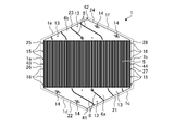
- FIG. 4 is a plan view of the first heat transfer plate in Embodiment 1.
- the first heat transfer plate 1 has a hexagonal shape in plan view.
- the air passage 3 is formed on one side of the first heat transfer plate 1
- the air passage 4 is formed on the first heat transfer plate 1.
- the first heat transfer plate 1 is provided with a heat exchange portion 5 for exchanging heat between the air passing through the air passage 3 and the air passing through the air passage 4 .
- the heat exchanging portion 5 has a side surface on which the first inflow surface 61, the first outflow surface 71, the second inflow surface 62, and the second outflow surface 72 are not formed among the side surfaces of the heat exchange element 50.
- the heat exchanging portion 5 is formed in a corrugated shape having a plurality of unevenness.
- the air passing through the air passage 3 and the air passing through the air passage 4 pass in parallel and in opposite directions.
- the first heat transfer plate 1 is provided with a first header portion 6a having a triangular shape in plan view.
- the first header portion 6 a has a side 1 c facing the first inflow surface 61 of the heat exchange element 50 and a side 1 d facing the second outflow surface 72 .
- the first heat transfer plate 1 is formed with a second header portion 6b having a triangular shape in plan view.
- the second header portion 6 b has a side 1 e facing the first outflow surface 71 of the heat exchange element 50 and a side 1 f facing the second inflow surface 62 .
- the first header portion 6a and the second header portion 6b are provided on one side and the other side with the heat exchange portion 5 interposed therebetween.
- the sides 1a and 1b of the first heat transfer plate 1 are sides that are not in contact with the first header portion 6a and the second header portion 6b.
- a rib 8 is formed on the first header portion 6a and the second header portion 6b.
- a rib 8 formed in the first header portion 6a extends toward the heat exchange portion 5 from the side 1c.
- the ribs 8 formed in the first header portion 6a extend substantially parallel to the side 1d, and smoothly pass the air flowing in from the first inflow surface 61, that is, the side 1c toward the heat exchange portion 5. .
- a step 41 is provided in order to allow the inflow of air from the side 1c and prevent the inflow of air from the side 1d.
- the outflow of air from the side 1e is allowed, and in order to prevent the outflow of air from the side 1f, there is a gap between the strip-shaped plane portion 23 and the strip-shaped plane portion 24 along the stacking direction.
- a step 42 is provided.
- the strip-shaped plane portion 23 is formed at a position below the region where the ribs 8 are formed, and the strip-shaped plane portion 24 is formed at a position above the strip-shaped plane portion 23 . It should be noted that the strip-shaped plane portion 23 and the region where the ribs 8 are formed may be formed on the same plane.
- strip-shaped plane portions 25 and 26 which are strip-shaped plane regions extending along the side 1a, are provided.
- the strip-shaped plane portion 25 and the strip-shaped plane portion 26 are formed with a step 43 provided between them at an intermediate portion in the direction along the side 1a.
- the flat strip portion 26 is formed above the flat strip portion 25 .
- strip-shaped plane portions 27 and 28 which are strip-shaped plane regions extending along the side 1b, are provided.
- the strip-shaped plane portion 27 and the strip-shaped plane portion 28 are formed with a step 44 provided between them at an intermediate portion in the direction along the side 1b.
- the flat strip portion 28 is formed above the flat strip portion 27 .
- the first heat transfer plate 1 has a point-symmetrical shape about the center position of a hexagon in plan view.
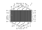
- FIG. 5 is a plan view of the second heat transfer plate in Embodiment 1.
- FIG. The second heat transfer plate 2 has a hexagonal shape in plan view. Components similar to those of the first heat transfer plate 1 are denoted by the same reference numerals, and detailed description thereof is omitted.
- the second heat transfer plate 2 is a mirror image of the first heat transfer plate 1 .
- the air passage 4 is formed on one side of the second heat transfer plate 2, and the air passage 3 is formed on the second heat transfer plate 2. is formed on the other side of the
- the second heat transfer plate 2 is provided with a heat exchange portion 5 for exchanging heat between the air passing through the air passage 3 and the air passing through the air passage 4 .
- the heat exchange portion 5 includes the first inflow surface 61 , the first outflow surface 71 , the second inflow surface 62 , the second outflow surface among the side surfaces of the heat exchange element 50 . It is formed of a rectangular region whose short sides are sides 2a and 2b facing the side surfaces where 72 is not formed.
- the second heat transfer plate 2 is provided with a third header portion 6c having a triangular shape in plan view.
- the third header portion 6 c has a side 2 c facing the first inflow surface 61 of the heat exchange element 50 and a side 2 d facing the second outflow surface 72 .
- the second heat transfer plate 2 is formed with a fourth header portion 6d having a triangular shape in plan view.
- the fourth header portion 6 d has a side 2 e facing the first outflow surface 71 of the heat exchange element 50 and a side 2 f facing the second inflow surface 62 .
- the third header portion 6c and the fourth header portion 6d are provided on one side and the other side with the heat exchange portion 5 interposed therebetween.
- the sides 2a and 2b of the second heat transfer plate 2 are sides that do not contact the third header portion 6c and the fourth header portion 6d.
- a rib 8 is formed on the third header portion 6c and the fourth header portion 6d.
- a rib 8 formed in the third header portion 6c extends toward the heat exchange portion 5 from the side 2d.
- the ribs 8 formed on the third header portion 6c extend substantially parallel to the side 2c, allowing the air from the heat exchange portion 5 to pass smoothly toward the side 2d.
- the rib 8 formed in the fourth header portion 6d extends from the side 2f toward the heat exchange portion 5.
- the ribs 8 formed on the fourth header portion 6d extend substantially parallel to the side 2e, and smoothly pass the air flowing in from the second inflow surface 62, that is, the side 2f toward the heat exchanging portion 5. .
- a step 51 is provided in the second heat transfer plate 2, in order to allow the air to flow out from the side 2d and prevent the air to flow out from the side 2c.
- the strip-shaped plane portion 32 is formed at a position below the region where the ribs 8 are formed, and the strip-shaped plane portion 31 is formed at a position above the strip-shaped plane portion 32 . It should be noted that the strip-shaped plane portion 32 and the region where the ribs 8 are formed may be formed on the same plane.
- a strip-shaped plane portion 33 which is a strip-shaped plane region extending along the side 2e, is provided on the outer edge of the fourth header portion 6d.
- a strip-shaped plane portion 34 which is a strip-shaped plane region extending along the side 2f, is provided on the outer edge of the fourth header portion 6d.
- the inflow of air from the side 2f is allowed, and in order to prevent the inflow of air from the side 2e, there is a gap between the strip-shaped plane portion 33 and the strip-shaped plane portion 34 along the stacking direction.
- a step 52 is provided.
- strip-shaped plane portions 35 and 36 which are strip-shaped plane regions extending along the side 2a, are provided.
- the strip-shaped plane portion 35 and the strip-shaped plane portion 36 are formed with a step 53 provided at an intermediate portion in the direction along the side 2a.
- the strip-shaped flat portion 35 is formed above the strip-shaped flat portion 36 .
- strip-shaped plane portions 37 and 38 which are strip-shaped plane regions extending along the side 2b, are provided.
- the strip-shaped plane portion 37 and the strip-shaped plane portion 38 are formed with a step 54 provided between them at the intermediate portion in the direction along the side 2b.
- the flat strip portion 37 is formed above the flat strip portion 38 .
- the second heat transfer plate 2 has a point-symmetrical shape about the center position of the hexagon in plan view.
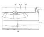
- FIG. 6 is a partially enlarged sectional view enlarging the protrusion and the base portion in the heat exchange element according to the first embodiment.
- FIG. 7 is a partially enlarged perspective cross-sectional view of the heat exchange element according to the first embodiment, in which the projection and the base portion are enlarged.
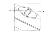
- 8 is a plan view of the pedestal according to Embodiment 1.
- the protrusion 13 is formed so as to protrude downward.
- the protrusion 13 is a second protrusion.
- the rear surface of the protrusion 13 is a recess.
- a plurality of protrusions 13 are formed along sides 1c, 1e, 2d, and 2f serving as air inlets and outlets.
- a plurality of projections 13 are formed on each side 1c, 1e, 2d and 2f.
- the projections 13 are formed at positions dividing the lengths of the sides 1c, 1e, 2d, and 2f at equal intervals.
- the height of the projection 13 has a ratio of 1 or less to the diameter at the root of the projection 13 . With this ratio, when the heat transfer plates 1 and 2 are formed by vacuum forming, it is possible to prevent the material from becoming too thin and forming holes.
- the pedestal 14 is formed so as to protrude upward.
- the pedestal 14 has a trapezoidal cross-sectional shape.
- a flat area is provided on the top of the pedestal 14, and a recess 14a that is recessed downward is formed in the flat area.
- the planar shape of the pedestal 14 is a diamond shape.
- the recess 14a has an elongated hole shape whose longitudinal direction is the direction toward the center of the heat transfer plates 1 and 2 in a plan view.
- the width of the recess 14a along the width direction is a width in which the protrusion 13 is fitted.
- the projection 13 and the base 14 are formed at positions that overlap each other in a plan view when the first heat transfer plate 1 and the second heat transfer plate 2 are stacked. As shown in FIGS. 6 and 7 , when the heat transfer plates 1 and 2 are stacked, the planar area of the top of the pedestal 14 contacts the heat transfer plates 1 and 2 stacked above. Also, the projection 13 fits into the recess 14a of the base 14. As shown in FIG. Since the protrusion 13 is fitted in the recess 14a, it is not exposed to the air paths 3 and 4. - ⁇ Note that the projection 13 may protrude upward and the pedestal 14 may protrude downward.
- the cone cover 15 is formed on the strip-shaped plane portions 25, 27, 36, 38 of the heat transfer plates 1, 2.
- a plurality of cone covers 15 are formed for each of the strip-shaped plane portions 25 , 27 , 36 , 38 .
- the cone cover 15 is formed at a position that divides the length of each strip-shaped plane portion 25, 27, 36, 38 into equal intervals.
- the cone cover 15 is formed at a position closer to the heat exchanging portion 5 than the widthwise center of each of the flat strip portions 25 , 27 , 36 , 38 .
- the cone 16 is a first convex part that is convex upward.
- the cone 16 is formed in a conical shape with a curved tip.
- the flat strip portion 21 contacts the flat strip portion 31 below.
- the flat strip portion 22 abuts on the flat strip portion 32 above.
- the flat strip portion 23 contacts the flat strip portion 33 below.
- the flat strip portion 24 abuts on the flat strip portion 34 above.
- the flat strip portion 25 contacts the flat strip portion 35 below.
- the flat strip portion 26 abuts on the flat strip portion 36 above.
- the flat strip portion 27 abuts on the flat strip portion 37 below.
- the flat strip portion 28 contacts the flat strip portion 38 above.
- the contacting flat strips 21, 22, 23, 24, 25, 26, 27, 28, 31, 32, 33, 34, 35, 36, 37, and 38 are joined by ultrasonic welding. It becomes the joint edge that is connected.
- the cone cover 15 and the cone 16 are formed at positions that overlap each other in plan view when the heat transfer plates 1 and 2 are laminated.
- the cone 16 fits into the recess of the cone cover 15.
- the concave portion of the cone cover 15 may be concaved downward, and the cone 16 may be convex downward.
- 13 to 16 are diagrams showing manufacturing steps of the heat exchange element according to the first embodiment.
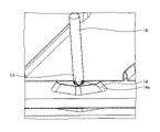
- the protrusion 13 fits into the hole of the receiving base 17 and is positioned.
- the tips of the guide pins 18 are fitted into the recesses on the rear surface of the protrusions 13 of the second heat transfer plate 2 to be laminated next, and then, as shown in FIG.
- the heat transfer plates 2 are laminated.
- the belt-like plane portions 22, 24, 26, 28, 32, 34, 36, and 38 that are in contact with each other are arranged in a state in which both the upper and lower heat transfer plates 1 and 2 are positioned by the manufacturing apparatus. is fixed by ultrasonic welding.
- the first heat transfer plate 1 to be laminated next is laminated while being positioned using guide pins 19 .
- the tips of the guide pins 18 and 19 are fitted into the concave portions on the back surface of the protrusion 13, and the upper heat transfer plates 1 and 2 are pressed against the lower heat transfer plates 1 and 2, so that the protrusion 13 is fitted. Frictional resistance is generated between the flat portion of the pedestal 14 and the areas of the header portions 6a, 6b, 6c, 6d that contact the flat portion of the pedestal 14. As shown in FIG. This improves the reliability of ultrasonic welding and improves the yield.
- the protrusions 13, the pedestal 14, the cone cover 15, and the cone 16 formed on the heat transfer plates 1 and 2 make it difficult for misalignment to occur in the stacked state. Therefore, the heat transfer plates 1 and 2 are less likely to be misaligned even by ultrasonic welding that vibrates the heat transfer plates 1 and 2 . Further, simply by stacking the heat transfer plates 1 and 2, the protrusions 13 are fitted into the recesses 14a of the pedestal 14, and the cones 16 are fitted into the cone cover 15, so that positioning can be performed accurately and easily. Further, if the projection 13 is tightly fitted in the recess 14a of the base 14 and the cone 16 is tightly fitted in the cone cover 15, it is possible to further prevent misalignment.
- the heat transfer plates 1 and 2 shrink toward the center after molding. Since the recess 14a has an elongated hole shape whose longitudinal direction is the direction toward the center of the heat transfer plates 1 and 2 in plan view, the position of the pedestal 14 is shifted by the contraction toward the center of the heat transfer plates 1 and 2. Even if it is displaced, the projection 13 is easily fitted into the recess 14a. Further, since the heat transfer plates 1 and 2 are prevented from being displaced in a direction different from the direction toward the center of the heat transfer plates 1 and 2 due to the contact between the protrusions 13 and the recesses 14a, the positioning accuracy can be improved. be done.
- the projection 13 and the base 14 are located near the belt-like plane portions 22, 24, 31, and 33 even within the areas of the header portions 6a, 6b, 6c, and 6d. Since it is in the parts 25, 26, 27, 28, 35, 36, 37, 38, even if a force to shift the heat transfer plates 1, 2 by ultrasonic welding acts, the bending stress generated in the heat transfer plates 1, 2 stays within a short distance, it is possible to make it difficult for the heat transfer plate to bend.
- the protrusion 13, the pedestal 14, the cone cover 15, and the cone 16 each have a belt-like plane portion 21, 22, 23, 24, 25, 26, 27, 28, 31, 32, 33, 34, 35, 36, 37, By forming a plurality of grooves with respect to 38, it becomes even more difficult for misalignment to occur.
- the base 14 is provided so that the longer diagonal of the two diagonals of the rhombus is aligned with the direction of air flow, and the top of the base 14 is in contact with the adjacent heat transfer plates 1 and 2. Therefore, the pedestal 14 is less likely to obstruct the flow of air.
- the flow of air around the base 14 and the sides 1d, 1f, 2c, and 2e is reduced compared to the case where no gap is provided. turbulence can be reduced, and the occurrence of pressure loss can be suppressed.
- the pedestals 14 linearly in the air flow direction, it is possible to similarly reduce turbulence in the air flow and suppress the occurrence of pressure loss. By arranging the pedestal 14 and the sides 1d, 1f, 2c and 2e as close to each other as possible with a gap therebetween, the distance between the welding point and the pedestal 14 becomes as short as possible, and positioning during welding can be made more effective.
- the bases 14 are provided on the header portions 6a, 6b, 6c, and 6d, the bases 14 are provided on the flat strip portions 21, 22, 23, 24, 31, 32, 33, and 34, respectively.
- the width of 21, 22, 23, 24, 31, 32, 33, 34 can be narrowed. If the heat transfer plates 1 and 2 are of the same size, the narrower the width of the flat strip portions 21, 22, 23, 24, 31, 32, 33, 34, the wider the header portions 6a, 6b, 6c, 6d. .
- the pedestal 14 is provided in the flow path, the pedestal 14 can be attached to the strip-shaped plane portions 21, 22, 23, 24, 31, 32, 33, and 34 by widening the header portions 6a, 6b, 6c, and 6d.
- the pressure loss of the heat exchange element 50 can be made lower than when it is provided.
- the configuration shown in the above embodiment shows an example of the content of the present disclosure.
- the configuration of the embodiment can be combined with another known technique. A part of the configuration of the embodiment can be omitted or changed without departing from the gist of the present disclosure.
Landscapes
- Engineering & Computer Science (AREA)
- Physics & Mathematics (AREA)
- Thermal Sciences (AREA)
- Mechanical Engineering (AREA)
- General Engineering & Computer Science (AREA)
- Heat-Exchange Devices With Radiators And Conduit Assemblies (AREA)
Priority Applications (6)
| Application Number | Priority Date | Filing Date | Title |
|---|---|---|---|
| CN202180100277.XA CN117651841A (zh) | 2021-07-12 | 2021-07-12 | 热交换元件 |
| EP21950054.3A EP4372304B1 (en) | 2021-07-12 | 2021-07-12 | Heat exchange element |
| US18/559,975 US20240240880A1 (en) | 2021-07-12 | 2021-07-12 | Heat exchange element |
| JP2023534435A JP7599567B2 (ja) | 2021-07-12 | 2021-07-12 | 熱交換素子 |
| CA3226203A CA3226203A1 (en) | 2021-07-12 | 2021-07-12 | Heat exchange element |
| PCT/JP2021/026095 WO2023286110A1 (ja) | 2021-07-12 | 2021-07-12 | 熱交換素子 |
Applications Claiming Priority (1)
| Application Number | Priority Date | Filing Date | Title |
|---|---|---|---|
| PCT/JP2021/026095 WO2023286110A1 (ja) | 2021-07-12 | 2021-07-12 | 熱交換素子 |
Publications (1)
| Publication Number | Publication Date |
|---|---|
| WO2023286110A1 true WO2023286110A1 (ja) | 2023-01-19 |
Family
ID=84919145
Family Applications (1)
| Application Number | Title | Priority Date | Filing Date |
|---|---|---|---|
| PCT/JP2021/026095 Ceased WO2023286110A1 (ja) | 2021-07-12 | 2021-07-12 | 熱交換素子 |
Country Status (6)
| Country | Link |
|---|---|
| US (1) | US20240240880A1 (https=) |
| EP (1) | EP4372304B1 (https=) |
| JP (1) | JP7599567B2 (https=) |
| CN (1) | CN117651841A (https=) |
| CA (1) | CA3226203A1 (https=) |
| WO (1) | WO2023286110A1 (https=) |
Citations (4)
| Publication number | Priority date | Publication date | Assignee | Title |
|---|---|---|---|---|
| JP2004003824A (ja) * | 2002-03-28 | 2004-01-08 | Matsushita Ecology Systems Co Ltd | 熱交換器 |
| JP2004293862A (ja) | 2003-03-26 | 2004-10-21 | Matsushita Electric Ind Co Ltd | 熱交換器 |
| JP2007285691A (ja) * | 2006-03-22 | 2007-11-01 | Matsushita Electric Ind Co Ltd | 熱交換器 |
| JP2008107071A (ja) * | 2006-09-28 | 2008-05-08 | Matsushita Electric Ind Co Ltd | 熱交換素子 |
Family Cites Families (4)
| Publication number | Priority date | Publication date | Assignee | Title |
|---|---|---|---|---|
| KR100724225B1 (ko) * | 2005-11-30 | 2007-05-31 | 마쓰시타 에코시스테무즈 가부시키가이샤 | 열교환기 |
| KR100783599B1 (ko) * | 2007-03-09 | 2007-12-07 | 충남대학교산학협력단 | 환기장치용 열교환기 |
| CN102183077A (zh) * | 2011-01-30 | 2011-09-14 | 霍尼韦尔(中国)有限公司 | 能量回收装置 |
| NL2018175B1 (nl) | 2017-01-16 | 2018-07-26 | Recair Holding B V | Recuperator |
-
2021
- 2021-07-12 JP JP2023534435A patent/JP7599567B2/ja active Active
- 2021-07-12 CA CA3226203A patent/CA3226203A1/en active Pending
- 2021-07-12 EP EP21950054.3A patent/EP4372304B1/en active Active
- 2021-07-12 WO PCT/JP2021/026095 patent/WO2023286110A1/ja not_active Ceased
- 2021-07-12 CN CN202180100277.XA patent/CN117651841A/zh active Pending
- 2021-07-12 US US18/559,975 patent/US20240240880A1/en active Pending
Patent Citations (4)
| Publication number | Priority date | Publication date | Assignee | Title |
|---|---|---|---|---|
| JP2004003824A (ja) * | 2002-03-28 | 2004-01-08 | Matsushita Ecology Systems Co Ltd | 熱交換器 |
| JP2004293862A (ja) | 2003-03-26 | 2004-10-21 | Matsushita Electric Ind Co Ltd | 熱交換器 |
| JP2007285691A (ja) * | 2006-03-22 | 2007-11-01 | Matsushita Electric Ind Co Ltd | 熱交換器 |
| JP2008107071A (ja) * | 2006-09-28 | 2008-05-08 | Matsushita Electric Ind Co Ltd | 熱交換素子 |
Non-Patent Citations (1)
| Title |
|---|
| See also references of EP4372304A4 |
Also Published As
| Publication number | Publication date |
|---|---|
| JP7599567B2 (ja) | 2024-12-13 |
| EP4372304B1 (en) | 2025-09-03 |
| CN117651841A (zh) | 2024-03-05 |
| EP4372304A4 (en) | 2024-08-21 |
| JPWO2023286110A1 (https=) | 2023-01-19 |
| US20240240880A1 (en) | 2024-07-18 |
| EP4372304A1 (en) | 2024-05-22 |
| CA3226203A1 (en) | 2023-01-19 |
Similar Documents
| Publication | Publication Date | Title |
|---|---|---|
| JP6590917B2 (ja) | プレート積層型熱交換器 | |
| KR101353716B1 (ko) | 판 열교환기 | |
| JP4816517B2 (ja) | 熱交換素子 | |
| CN101346597A (zh) | 用于在口区域中具有均匀负载分配的板式换热器的传热板 | |
| JP6660883B2 (ja) | プレート式熱交換器のための熱交換プレートおよび前記熱交換プレートが設けられたプレート式熱交換器 | |
| CN113424009A (zh) | 热交换器 | |
| JP5724710B2 (ja) | プレート積層型冷却器 | |
| JP2004184075A (ja) | 伝熱プレート及びプレート式熱交換器 | |
| WO2023286110A1 (ja) | 熱交換素子 | |
| JP2008116138A (ja) | 熱交換用プレート | |
| JP3146246B1 (ja) | プレート式熱交換器及びその溶接方法 | |
| JP6545920B2 (ja) | 熱交換器 | |
| KR100918607B1 (ko) | 판형 열교환기의 열교환판 결합방법 및 결합장치, 이에의한 판형 열교환기의 열교환판 결합구조 | |
| JP6249611B2 (ja) | 積層構造体 | |
| KR101317920B1 (ko) | 인쇄기판형 열교환기 및 이의 제작방법 | |
| KR101980359B1 (ko) | 적층식 판형 열교환기 | |
| JP7210646B2 (ja) | ヒートシンク及び熱交換器 | |
| JP2024524503A (ja) | 熱交換器及びその製造方法 | |
| JP2005207725A (ja) | 熱交換器 | |
| JP2006317026A (ja) | 積層型熱交換器及びその製造方法 | |
| JP2547545Y2 (ja) | 積層型熱交換器 | |
| JP7800259B2 (ja) | 冷却装置、冷却装置の製造方法 | |
| JP2510115Y2 (ja) | 積層型熱交換器 | |
| JP2023165568A (ja) | プレート式熱交換器 | |
| JP2000320986A (ja) | プレート式熱交換器 |
Legal Events
| Date | Code | Title | Description |
|---|---|---|---|
| 121 | Ep: the epo has been informed by wipo that ep was designated in this application |
Ref document number: 21950054 Country of ref document: EP Kind code of ref document: A1 |
|
| ENP | Entry into the national phase |
Ref document number: 2023534435 Country of ref document: JP Kind code of ref document: A |
|
| WWE | Wipo information: entry into national phase |
Ref document number: 18559975 Country of ref document: US |
|
| WWE | Wipo information: entry into national phase |
Ref document number: 3226203 Country of ref document: CA |
|
| WWE | Wipo information: entry into national phase |
Ref document number: 202180100277.X Country of ref document: CN |
|
| WWE | Wipo information: entry into national phase |
Ref document number: 2021950054 Country of ref document: EP |
|
| NENP | Non-entry into the national phase |
Ref country code: DE |
|
| ENP | Entry into the national phase |
Ref document number: 2021950054 Country of ref document: EP Effective date: 20240212 |
|
| WWG | Wipo information: grant in national office |
Ref document number: 2021950054 Country of ref document: EP |