WO2023282295A1 - 化粧シート、及び化粧シートの製造方法 - Google Patents
化粧シート、及び化粧シートの製造方法 Download PDFInfo
- Publication number
- WO2023282295A1 WO2023282295A1 PCT/JP2022/026859 JP2022026859W WO2023282295A1 WO 2023282295 A1 WO2023282295 A1 WO 2023282295A1 JP 2022026859 W JP2022026859 W JP 2022026859W WO 2023282295 A1 WO2023282295 A1 WO 2023282295A1
- Authority
- WO
- WIPO (PCT)
- Prior art keywords
- decorative sheet
- protective layer
- less
- surface protective
- light
- Prior art date
Links
- 238000004519 manufacturing process Methods 0.000 title claims abstract description 13
- 229920005989 resin Polymers 0.000 claims abstract description 75
- 239000011347 resin Substances 0.000 claims abstract description 75
- 239000000463 material Substances 0.000 claims abstract description 31
- 239000004925 Acrylic resin Substances 0.000 claims abstract description 24
- TXBCBTDQIULDIA-UHFFFAOYSA-N 2-[[3-hydroxy-2,2-bis(hydroxymethyl)propoxy]methyl]-2-(hydroxymethyl)propane-1,3-diol Chemical group OCC(CO)(CO)COCC(CO)(CO)CO TXBCBTDQIULDIA-UHFFFAOYSA-N 0.000 claims abstract description 14
- IAYPIBMASNFSPL-UHFFFAOYSA-N Ethylene oxide Chemical compound C1CO1 IAYPIBMASNFSPL-UHFFFAOYSA-N 0.000 claims abstract description 12
- 229920000178 Acrylic resin Polymers 0.000 claims abstract description 11
- GOOHAUXETOMSMM-UHFFFAOYSA-N Propylene oxide Chemical compound CC1CO1 GOOHAUXETOMSMM-UHFFFAOYSA-N 0.000 claims abstract description 8
- PAPBSGBWRJIAAV-UHFFFAOYSA-N ε-Caprolactone Chemical group O=C1CCCCCO1 PAPBSGBWRJIAAV-UHFFFAOYSA-N 0.000 claims abstract description 7
- 239000011241 protective layer Substances 0.000 claims description 115
- 239000010410 layer Substances 0.000 claims description 103
- 239000002245 particle Substances 0.000 claims description 41
- 230000005865 ionizing radiation Effects 0.000 claims description 33
- 239000004744 fabric Substances 0.000 claims description 22
- 238000000034 method Methods 0.000 claims description 15
- 230000001678 irradiating effect Effects 0.000 claims description 7
- 125000003647 acryloyl group Chemical group O=C([*])C([H])=C([H])[H] 0.000 claims description 4
- 238000013461 design Methods 0.000 abstract description 9
- 238000000576 coating method Methods 0.000 description 22
- 238000011156 evaluation Methods 0.000 description 19
- 239000007788 liquid Substances 0.000 description 17
- 239000011248 coating agent Substances 0.000 description 16
- 239000007789 gas Substances 0.000 description 13
- 239000012790 adhesive layer Substances 0.000 description 12
- -1 wooden boards Substances 0.000 description 12
- 238000006243 chemical reaction Methods 0.000 description 10
- NIXOWILDQLNWCW-UHFFFAOYSA-M Acrylate Chemical compound [O-]C(=O)C=C NIXOWILDQLNWCW-UHFFFAOYSA-M 0.000 description 9
- 239000003795 chemical substances by application Substances 0.000 description 9
- 229920001577 copolymer Polymers 0.000 description 8
- 238000007639 printing Methods 0.000 description 8
- 238000012360 testing method Methods 0.000 description 8
- MPIAGWXWVAHQBB-UHFFFAOYSA-N [3-prop-2-enoyloxy-2-[[3-prop-2-enoyloxy-2,2-bis(prop-2-enoyloxymethyl)propoxy]methyl]-2-(prop-2-enoyloxymethyl)propyl] prop-2-enoate Chemical compound C=CC(=O)OCC(COC(=O)C=C)(COC(=O)C=C)COCC(COC(=O)C=C)(COC(=O)C=C)COC(=O)C=C MPIAGWXWVAHQBB-UHFFFAOYSA-N 0.000 description 7
- 239000000853 adhesive Substances 0.000 description 7
- 230000001070 adhesive effect Effects 0.000 description 7
- 230000000052 comparative effect Effects 0.000 description 7
- 229920001971 elastomer Polymers 0.000 description 7
- 229910052751 metal Inorganic materials 0.000 description 7
- 239000002184 metal Substances 0.000 description 7
- 239000000123 paper Substances 0.000 description 7
- 239000005060 rubber Substances 0.000 description 7
- 239000000758 substrate Substances 0.000 description 7
- 230000002123 temporal effect Effects 0.000 description 7
- VGGSQFUCUMXWEO-UHFFFAOYSA-N Ethene Chemical compound C=C VGGSQFUCUMXWEO-UHFFFAOYSA-N 0.000 description 6
- 239000005977 Ethylene Substances 0.000 description 6
- 239000003607 modifier Substances 0.000 description 6
- 239000000049 pigment Substances 0.000 description 6
- GWEVSGVZZGPLCZ-UHFFFAOYSA-N Titan oxide Chemical compound O=[Ti]=O GWEVSGVZZGPLCZ-UHFFFAOYSA-N 0.000 description 5
- 239000000654 additive Substances 0.000 description 5
- 230000003666 anti-fingerprint Effects 0.000 description 5
- 239000004611 light stabiliser Substances 0.000 description 5
- JRZJOMJEPLMPRA-UHFFFAOYSA-N olefin Natural products CCCCCCCC=C JRZJOMJEPLMPRA-UHFFFAOYSA-N 0.000 description 5
- XLYOFNOQVPJJNP-UHFFFAOYSA-N water Substances O XLYOFNOQVPJJNP-UHFFFAOYSA-N 0.000 description 5
- JOYRKODLDBILNP-UHFFFAOYSA-N Ethyl urethane Chemical compound CCOC(N)=O JOYRKODLDBILNP-UHFFFAOYSA-N 0.000 description 4
- UQSXHKLRYXJYBZ-UHFFFAOYSA-N Iron oxide Chemical compound [Fe]=O UQSXHKLRYXJYBZ-UHFFFAOYSA-N 0.000 description 4
- 239000004743 Polypropylene Substances 0.000 description 4
- VYPSYNLAJGMNEJ-UHFFFAOYSA-N Silicium dioxide Chemical compound O=[Si]=O VYPSYNLAJGMNEJ-UHFFFAOYSA-N 0.000 description 4
- 239000012298 atmosphere Substances 0.000 description 4
- TZCXTZWJZNENPQ-UHFFFAOYSA-L barium sulfate Chemical compound [Ba+2].[O-]S([O-])(=O)=O TZCXTZWJZNENPQ-UHFFFAOYSA-L 0.000 description 4
- 230000001186 cumulative effect Effects 0.000 description 4
- 238000010586 diagram Methods 0.000 description 4
- 238000009826 distribution Methods 0.000 description 4
- 238000007646 gravure printing Methods 0.000 description 4
- 239000002932 luster Substances 0.000 description 4
- 238000012545 processing Methods 0.000 description 4
- 239000004698 Polyethylene Substances 0.000 description 3
- 229910000831 Steel Inorganic materials 0.000 description 3
- 235000010724 Wisteria floribunda Nutrition 0.000 description 3
- NIXOWILDQLNWCW-UHFFFAOYSA-N acrylic acid group Chemical group C(C=C)(=O)O NIXOWILDQLNWCW-UHFFFAOYSA-N 0.000 description 3
- 230000000996 additive effect Effects 0.000 description 3
- 150000001336 alkenes Chemical class 0.000 description 3
- 229910052782 aluminium Inorganic materials 0.000 description 3
- XAGFODPZIPBFFR-UHFFFAOYSA-N aluminium Chemical compound [Al] XAGFODPZIPBFFR-UHFFFAOYSA-N 0.000 description 3
- QVGXLLKOCUKJST-UHFFFAOYSA-N atomic oxygen Chemical compound [O] QVGXLLKOCUKJST-UHFFFAOYSA-N 0.000 description 3
- 239000011230 binding agent Substances 0.000 description 3
- 230000008859 change Effects 0.000 description 3
- 239000003086 colorant Substances 0.000 description 3
- 238000004132 cross linking Methods 0.000 description 3
- 238000007756 gravure coating Methods 0.000 description 3
- 238000010030 laminating Methods 0.000 description 3
- 239000004745 nonwoven fabric Substances 0.000 description 3
- 239000003960 organic solvent Substances 0.000 description 3
- 229910052760 oxygen Inorganic materials 0.000 description 3
- 239000001301 oxygen Substances 0.000 description 3
- 229920001200 poly(ethylene-vinyl acetate) Polymers 0.000 description 3
- 229920000728 polyester Polymers 0.000 description 3
- 229920001155 polypropylene Polymers 0.000 description 3
- 229920002635 polyurethane Polymers 0.000 description 3
- 239000004814 polyurethane Substances 0.000 description 3
- 239000010959 steel Substances 0.000 description 3
- 229920003002 synthetic resin Polymers 0.000 description 3
- 239000000057 synthetic resin Substances 0.000 description 3
- 210000002268 wool Anatomy 0.000 description 3
- VXNZUUAINFGPBY-UHFFFAOYSA-N 1-Butene Chemical compound CCC=C VXNZUUAINFGPBY-UHFFFAOYSA-N 0.000 description 2
- ZGEGCLOFRBLKSE-UHFFFAOYSA-N 1-Heptene Chemical compound CCCCCC=C ZGEGCLOFRBLKSE-UHFFFAOYSA-N 0.000 description 2
- AFFLGGQVNFXPEV-UHFFFAOYSA-N 1-decene Chemical compound CCCCCCCCC=C AFFLGGQVNFXPEV-UHFFFAOYSA-N 0.000 description 2
- CRSBERNSMYQZNG-UHFFFAOYSA-N 1-dodecene Chemical compound CCCCCCCCCCC=C CRSBERNSMYQZNG-UHFFFAOYSA-N 0.000 description 2
- ADOBXTDBFNCOBN-UHFFFAOYSA-N 1-heptadecene Chemical compound CCCCCCCCCCCCCCCC=C ADOBXTDBFNCOBN-UHFFFAOYSA-N 0.000 description 2
- GQEZCXVZFLOKMC-UHFFFAOYSA-N 1-hexadecene Chemical compound CCCCCCCCCCCCCCC=C GQEZCXVZFLOKMC-UHFFFAOYSA-N 0.000 description 2
- LIKMAJRDDDTEIG-UHFFFAOYSA-N 1-hexene Chemical compound CCCCC=C LIKMAJRDDDTEIG-UHFFFAOYSA-N 0.000 description 2
- KWKAKUADMBZCLK-UHFFFAOYSA-N 1-octene Chemical compound CCCCCCC=C KWKAKUADMBZCLK-UHFFFAOYSA-N 0.000 description 2
- PJLHTVIBELQURV-UHFFFAOYSA-N 1-pentadecene Chemical compound CCCCCCCCCCCCCC=C PJLHTVIBELQURV-UHFFFAOYSA-N 0.000 description 2
- HFDVRLIODXPAHB-UHFFFAOYSA-N 1-tetradecene Chemical compound CCCCCCCCCCCCC=C HFDVRLIODXPAHB-UHFFFAOYSA-N 0.000 description 2
- DCTOHCCUXLBQMS-UHFFFAOYSA-N 1-undecene Chemical compound CCCCCCCCCC=C DCTOHCCUXLBQMS-UHFFFAOYSA-N 0.000 description 2
- FDSUVTROAWLVJA-UHFFFAOYSA-N 2-[[3-hydroxy-2,2-bis(hydroxymethyl)propoxy]methyl]-2-(hydroxymethyl)propane-1,3-diol;prop-2-enoic acid Chemical compound OC(=O)C=C.OC(=O)C=C.OC(=O)C=C.OC(=O)C=C.OC(=O)C=C.OCC(CO)(CO)COCC(CO)(CO)CO FDSUVTROAWLVJA-UHFFFAOYSA-N 0.000 description 2
- WSSSPWUEQFSQQG-UHFFFAOYSA-N 4-methyl-1-pentene Chemical compound CC(C)CC=C WSSSPWUEQFSQQG-UHFFFAOYSA-N 0.000 description 2
- KWOLFJPFCHCOCG-UHFFFAOYSA-N Acetophenone Chemical compound CC(=O)C1=CC=CC=C1 KWOLFJPFCHCOCG-UHFFFAOYSA-N 0.000 description 2
- VTYYLEPIZMXCLO-UHFFFAOYSA-L Calcium carbonate Chemical compound [Ca+2].[O-]C([O-])=O VTYYLEPIZMXCLO-UHFFFAOYSA-L 0.000 description 2
- 239000004593 Epoxy Substances 0.000 description 2
- OAKJQQAXSVQMHS-UHFFFAOYSA-N Hydrazine Chemical compound NN OAKJQQAXSVQMHS-UHFFFAOYSA-N 0.000 description 2
- XEEYBQQBJWHFJM-UHFFFAOYSA-N Iron Chemical compound [Fe] XEEYBQQBJWHFJM-UHFFFAOYSA-N 0.000 description 2
- CPLXHLVBOLITMK-UHFFFAOYSA-N Magnesium oxide Chemical compound [Mg]=O CPLXHLVBOLITMK-UHFFFAOYSA-N 0.000 description 2
- BQCADISMDOOEFD-UHFFFAOYSA-N Silver Chemical compound [Ag] BQCADISMDOOEFD-UHFFFAOYSA-N 0.000 description 2
- MCMNRKCIXSYSNV-UHFFFAOYSA-N Zirconium dioxide Chemical compound O=[Zr]=O MCMNRKCIXSYSNV-UHFFFAOYSA-N 0.000 description 2
- PNEYBMLMFCGWSK-UHFFFAOYSA-N aluminium oxide Inorganic materials [O-2].[O-2].[O-2].[Al+3].[Al+3] PNEYBMLMFCGWSK-UHFFFAOYSA-N 0.000 description 2
- 150000001412 amines Chemical class 0.000 description 2
- 238000005452 bending Methods 0.000 description 2
- RWCCWEUUXYIKHB-UHFFFAOYSA-N benzophenone Chemical compound C=1C=CC=CC=1C(=O)C1=CC=CC=C1 RWCCWEUUXYIKHB-UHFFFAOYSA-N 0.000 description 2
- 239000012965 benzophenone Substances 0.000 description 2
- 238000004140 cleaning Methods 0.000 description 2
- 238000013329 compounding Methods 0.000 description 2
- 238000011109 contamination Methods 0.000 description 2
- 238000003851 corona treatment Methods 0.000 description 2
- 230000006866 deterioration Effects 0.000 description 2
- 238000001035 drying Methods 0.000 description 2
- 238000010894 electron beam technology Methods 0.000 description 2
- 239000005038 ethylene vinyl acetate Substances 0.000 description 2
- 239000011888 foil Substances 0.000 description 2
- PCHJSUWPFVWCPO-UHFFFAOYSA-N gold Chemical compound [Au] PCHJSUWPFVWCPO-UHFFFAOYSA-N 0.000 description 2
- 229910052737 gold Inorganic materials 0.000 description 2
- 239000010931 gold Substances 0.000 description 2
- 239000012760 heat stabilizer Substances 0.000 description 2
- 239000011256 inorganic filler Substances 0.000 description 2
- 229910003475 inorganic filler Inorganic materials 0.000 description 2
- 238000001840 matrix-assisted laser desorption--ionisation time-of-flight mass spectrometry Methods 0.000 description 2
- 150000002739 metals Chemical class 0.000 description 2
- 239000000203 mixture Substances 0.000 description 2
- 238000012986 modification Methods 0.000 description 2
- 230000004048 modification Effects 0.000 description 2
- 239000000178 monomer Substances 0.000 description 2
- VAMFXQBUQXONLZ-UHFFFAOYSA-N n-alpha-eicosene Natural products CCCCCCCCCCCCCCCCCCC=C VAMFXQBUQXONLZ-UHFFFAOYSA-N 0.000 description 2
- 229910052756 noble gas Inorganic materials 0.000 description 2
- NHLUYCJZUXOUBX-UHFFFAOYSA-N nonadec-1-ene Chemical compound CCCCCCCCCCCCCCCCCC=C NHLUYCJZUXOUBX-UHFFFAOYSA-N 0.000 description 2
- CCCMONHAUSKTEQ-UHFFFAOYSA-N octadec-1-ene Chemical compound CCCCCCCCCCCCCCCCC=C CCCMONHAUSKTEQ-UHFFFAOYSA-N 0.000 description 2
- YWAKXRMUMFPDSH-UHFFFAOYSA-N pentene Chemical compound CCCC=C YWAKXRMUMFPDSH-UHFFFAOYSA-N 0.000 description 2
- 210000002381 plasma Anatomy 0.000 description 2
- 229920000573 polyethylene Polymers 0.000 description 2
- 230000001681 protective effect Effects 0.000 description 2
- 239000000377 silicon dioxide Substances 0.000 description 2
- 229910052709 silver Inorganic materials 0.000 description 2
- 239000004332 silver Substances 0.000 description 2
- 239000002904 solvent Substances 0.000 description 2
- 238000010186 staining Methods 0.000 description 2
- 239000002344 surface layer Substances 0.000 description 2
- OGIDPMRJRNCKJF-UHFFFAOYSA-N titanium oxide Inorganic materials [Ti]=O OGIDPMRJRNCKJF-UHFFFAOYSA-N 0.000 description 2
- 239000002023 wood Substances 0.000 description 2
- 229910052724 xenon Inorganic materials 0.000 description 2
- FHNFHKCVQCLJFQ-UHFFFAOYSA-N xenon atom Chemical compound [Xe] FHNFHKCVQCLJFQ-UHFFFAOYSA-N 0.000 description 2
- 239000004711 α-olefin Substances 0.000 description 2
- JYEUMXHLPRZUAT-UHFFFAOYSA-N 1,2,3-triazine Chemical compound C1=CN=NN=C1 JYEUMXHLPRZUAT-UHFFFAOYSA-N 0.000 description 1
- 229940106006 1-eicosene Drugs 0.000 description 1
- FIKTURVKRGQNQD-UHFFFAOYSA-N 1-eicosene Natural products CCCCCCCCCCCCCCCCCC=CC(O)=O FIKTURVKRGQNQD-UHFFFAOYSA-N 0.000 description 1
- GRWZFPFQSHTXHM-UHFFFAOYSA-N 11-methyldodec-1-ene Chemical compound CC(C)CCCCCCCCC=C GRWZFPFQSHTXHM-UHFFFAOYSA-N 0.000 description 1
- LPWUGKDQSNKUOQ-UHFFFAOYSA-N 12-ethyltetradec-1-ene Chemical compound CCC(CC)CCCCCCCCCC=C LPWUGKDQSNKUOQ-UHFFFAOYSA-N 0.000 description 1
- NLGDWWCZQDIASO-UHFFFAOYSA-N 2-hydroxy-1-(7-oxabicyclo[4.1.0]hepta-1,3,5-trien-2-yl)-2-phenylethanone Chemical compound OC(C(=O)c1cccc2Oc12)c1ccccc1 NLGDWWCZQDIASO-UHFFFAOYSA-N 0.000 description 1
- CAAMSDWKXXPUJR-UHFFFAOYSA-N 3,5-dihydro-4H-imidazol-4-one Chemical compound O=C1CNC=N1 CAAMSDWKXXPUJR-UHFFFAOYSA-N 0.000 description 1
- OLGHJTHQWQKJQQ-UHFFFAOYSA-N 3-ethylhex-1-ene Chemical compound CCCC(CC)C=C OLGHJTHQWQKJQQ-UHFFFAOYSA-N 0.000 description 1
- YPVPQMCSLFDIKA-UHFFFAOYSA-N 3-ethylpent-1-ene Chemical compound CCC(CC)C=C YPVPQMCSLFDIKA-UHFFFAOYSA-N 0.000 description 1
- YHQXBTXEYZIYOV-UHFFFAOYSA-N 3-methylbut-1-ene Chemical compound CC(C)C=C YHQXBTXEYZIYOV-UHFFFAOYSA-N 0.000 description 1
- LDTAOIUHUHHCMU-UHFFFAOYSA-N 3-methylpent-1-ene Chemical compound CCC(C)C=C LDTAOIUHUHHCMU-UHFFFAOYSA-N 0.000 description 1
- KLCNJIQZXOQYTE-UHFFFAOYSA-N 4,4-dimethylpent-1-ene Chemical compound CC(C)(C)CC=C KLCNJIQZXOQYTE-UHFFFAOYSA-N 0.000 description 1
- OPMUAJRVOWSBTP-UHFFFAOYSA-N 4-ethyl-1-hexene Chemical compound CCC(CC)CC=C OPMUAJRVOWSBTP-UHFFFAOYSA-N 0.000 description 1
- SUWJESCICIOQHO-UHFFFAOYSA-N 4-methylhex-1-ene Chemical compound CCC(C)CC=C SUWJESCICIOQHO-UHFFFAOYSA-N 0.000 description 1
- QNJMAPUHMGDDBE-UHFFFAOYSA-N 9-methyldec-1-ene Chemical compound CC(C)CCCCCCC=C QNJMAPUHMGDDBE-UHFFFAOYSA-N 0.000 description 1
- IJGRMHOSHXDMSA-UHFFFAOYSA-N Atomic nitrogen Chemical compound N#N IJGRMHOSHXDMSA-UHFFFAOYSA-N 0.000 description 1
- 238000012935 Averaging Methods 0.000 description 1
- OKTJSMMVPCPJKN-UHFFFAOYSA-N Carbon Chemical compound [C] OKTJSMMVPCPJKN-UHFFFAOYSA-N 0.000 description 1
- RYGMFSIKBFXOCR-UHFFFAOYSA-N Copper Chemical compound [Cu] RYGMFSIKBFXOCR-UHFFFAOYSA-N 0.000 description 1
- LFQSCWFLJHTTHZ-UHFFFAOYSA-N Ethanol Chemical compound CCO LFQSCWFLJHTTHZ-UHFFFAOYSA-N 0.000 description 1
- 239000004606 Fillers/Extenders Substances 0.000 description 1
- 239000000020 Nitrocellulose Substances 0.000 description 1
- CBENFWSGALASAD-UHFFFAOYSA-N Ozone Chemical compound [O-][O+]=O CBENFWSGALASAD-UHFFFAOYSA-N 0.000 description 1
- ISWSIDIOOBJBQZ-UHFFFAOYSA-N Phenol Chemical compound OC1=CC=CC=C1 ISWSIDIOOBJBQZ-UHFFFAOYSA-N 0.000 description 1
- OAICVXFJPJFONN-UHFFFAOYSA-N Phosphorus Chemical compound [P] OAICVXFJPJFONN-UHFFFAOYSA-N 0.000 description 1
- 239000004952 Polyamide Substances 0.000 description 1
- 239000004793 Polystyrene Substances 0.000 description 1
- 239000004372 Polyvinyl alcohol Substances 0.000 description 1
- NRCMAYZCPIVABH-UHFFFAOYSA-N Quinacridone Chemical compound N1C2=CC=CC=C2C(=O)C2=C1C=C1C(=O)C3=CC=CC=C3NC1=C2 NRCMAYZCPIVABH-UHFFFAOYSA-N 0.000 description 1
- NINIDFKCEFEMDL-UHFFFAOYSA-N Sulfur Chemical compound [S] NINIDFKCEFEMDL-UHFFFAOYSA-N 0.000 description 1
- RTAQQCXQSZGOHL-UHFFFAOYSA-N Titanium Chemical compound [Ti] RTAQQCXQSZGOHL-UHFFFAOYSA-N 0.000 description 1
- 229920002433 Vinyl chloride-vinyl acetate copolymer Polymers 0.000 description 1
- KNSXNCFKSZZHEA-UHFFFAOYSA-N [3-prop-2-enoyloxy-2,2-bis(prop-2-enoyloxymethyl)propyl] prop-2-enoate Chemical class C=CC(=O)OCC(COC(=O)C=C)(COC(=O)C=C)COC(=O)C=C KNSXNCFKSZZHEA-UHFFFAOYSA-N 0.000 description 1
- 239000006096 absorbing agent Substances 0.000 description 1
- 238000010306 acid treatment Methods 0.000 description 1
- BAPJBEWLBFYGME-UHFFFAOYSA-N acrylic acid methyl ester Natural products COC(=O)C=C BAPJBEWLBFYGME-UHFFFAOYSA-N 0.000 description 1
- 230000009471 action Effects 0.000 description 1
- SOGAXMICEFXMKE-UHFFFAOYSA-N alpha-Methyl-n-butyl acrylate Natural products CCCCOC(=O)C(C)=C SOGAXMICEFXMKE-UHFFFAOYSA-N 0.000 description 1
- 150000001408 amides Chemical class 0.000 description 1
- PYKYMHQGRFAEBM-UHFFFAOYSA-N anthraquinone Natural products CCC(=O)c1c(O)c2C(=O)C3C(C=CC=C3O)C(=O)c2cc1CC(=O)OC PYKYMHQGRFAEBM-UHFFFAOYSA-N 0.000 description 1
- 150000004056 anthraquinones Chemical class 0.000 description 1
- 239000003242 anti bacterial agent Substances 0.000 description 1
- 229940121375 antifungal agent Drugs 0.000 description 1
- 239000003429 antifungal agent Substances 0.000 description 1
- 238000000149 argon plasma sintering Methods 0.000 description 1
- 230000002238 attenuated effect Effects 0.000 description 1
- 125000000751 azo group Chemical group [*]N=N[*] 0.000 description 1
- 230000004888 barrier function Effects 0.000 description 1
- WPYMKLBDIGXBTP-UHFFFAOYSA-N benzoic acid Chemical compound OC(=O)C1=CC=CC=C1 WPYMKLBDIGXBTP-UHFFFAOYSA-N 0.000 description 1
- QRUDEWIWKLJBPS-UHFFFAOYSA-N benzotriazole Chemical compound C1=CC=C2N[N][N]C2=C1 QRUDEWIWKLJBPS-UHFFFAOYSA-N 0.000 description 1
- 239000012964 benzotriazole Substances 0.000 description 1
- 230000015572 biosynthetic process Effects 0.000 description 1
- 230000000903 blocking effect Effects 0.000 description 1
- QYMGIIIPAFAFRX-UHFFFAOYSA-N butyl prop-2-enoate;ethene Chemical compound C=C.CCCCOC(=O)C=C QYMGIIIPAFAFRX-UHFFFAOYSA-N 0.000 description 1
- 229910000019 calcium carbonate Inorganic materials 0.000 description 1
- 229910052799 carbon Inorganic materials 0.000 description 1
- 239000003054 catalyst Substances 0.000 description 1
- 239000001913 cellulose Substances 0.000 description 1
- 229920002678 cellulose Polymers 0.000 description 1
- 239000012459 cleaning agent Substances 0.000 description 1
- 238000004581 coalescence Methods 0.000 description 1
- 229910017052 cobalt Inorganic materials 0.000 description 1
- 239000010941 cobalt Substances 0.000 description 1
- GUTLYIVDDKVIGB-UHFFFAOYSA-N cobalt atom Chemical compound [Co] GUTLYIVDDKVIGB-UHFFFAOYSA-N 0.000 description 1
- 239000002131 composite material Substances 0.000 description 1
- 239000000470 constituent Substances 0.000 description 1
- 238000010276 construction Methods 0.000 description 1
- 239000000356 contaminant Substances 0.000 description 1
- 238000007334 copolymerization reaction Methods 0.000 description 1
- 229910052802 copper Inorganic materials 0.000 description 1
- 239000010949 copper Substances 0.000 description 1
- 238000005520 cutting process Methods 0.000 description 1
- 238000005034 decoration Methods 0.000 description 1
- 239000003599 detergent Substances 0.000 description 1
- CMMUKUYEPRGBFB-UHFFFAOYSA-L dichromic acid Chemical compound O[Cr](=O)(=O)O[Cr](O)(=O)=O CMMUKUYEPRGBFB-UHFFFAOYSA-L 0.000 description 1
- 238000007607 die coating method Methods 0.000 description 1
- 235000014113 dietary fatty acids Nutrition 0.000 description 1
- 229910001873 dinitrogen Inorganic materials 0.000 description 1
- 229940069096 dodecene Drugs 0.000 description 1
- 239000000975 dye Substances 0.000 description 1
- 230000000694 effects Effects 0.000 description 1
- 238000004049 embossing Methods 0.000 description 1
- 239000000839 emulsion Substances 0.000 description 1
- 230000007613 environmental effect Effects 0.000 description 1
- 229920006245 ethylene-butyl acrylate Polymers 0.000 description 1
- 230000001747 exhibiting effect Effects 0.000 description 1
- 238000002474 experimental method Methods 0.000 description 1
- 239000000194 fatty acid Substances 0.000 description 1
- 229930195729 fatty acid Natural products 0.000 description 1
- 150000004665 fatty acids Chemical class 0.000 description 1
- 238000009408 flooring Methods 0.000 description 1
- 239000012530 fluid Substances 0.000 description 1
- 239000006260 foam Substances 0.000 description 1
- 239000013538 functional additive Substances 0.000 description 1
- 230000004313 glare Effects 0.000 description 1
- 239000011521 glass Substances 0.000 description 1
- 230000005283 ground state Effects 0.000 description 1
- 229910052736 halogen Inorganic materials 0.000 description 1
- 150000002367 halogens Chemical class 0.000 description 1
- 229910052739 hydrogen Inorganic materials 0.000 description 1
- 239000003999 initiator Substances 0.000 description 1
- 238000007641 inkjet printing Methods 0.000 description 1
- 229910010272 inorganic material Inorganic materials 0.000 description 1
- 239000011147 inorganic material Substances 0.000 description 1
- 229910052742 iron Inorganic materials 0.000 description 1
- 239000012948 isocyanate Substances 0.000 description 1
- 150000002513 isocyanates Chemical class 0.000 description 1
- GWVMLCQWXVFZCN-UHFFFAOYSA-N isoindoline Chemical compound C1=CC=C2CNCC2=C1 GWVMLCQWXVFZCN-UHFFFAOYSA-N 0.000 description 1
- 239000000395 magnesium oxide Substances 0.000 description 1
- 238000012423 maintenance Methods 0.000 description 1
- 238000001819 mass spectrum Methods 0.000 description 1
- 238000000691 measurement method Methods 0.000 description 1
- 230000007246 mechanism Effects 0.000 description 1
- 239000010445 mica Substances 0.000 description 1
- 229910052618 mica group Inorganic materials 0.000 description 1
- 238000002156 mixing Methods 0.000 description 1
- TVMXDCGIABBOFY-UHFFFAOYSA-N n-Octanol Natural products CCCCCCCC TVMXDCGIABBOFY-UHFFFAOYSA-N 0.000 description 1
- 229920001220 nitrocellulos Polymers 0.000 description 1
- 238000007645 offset printing Methods 0.000 description 1
- 239000011368 organic material Substances 0.000 description 1
- 239000005416 organic matter Substances 0.000 description 1
- 229910052698 phosphorus Inorganic materials 0.000 description 1
- 239000011574 phosphorus Substances 0.000 description 1
- IEQIEDJGQAUEQZ-UHFFFAOYSA-N phthalocyanine Chemical compound N1C(N=C2C3=CC=CC=C3C(N=C3C4=CC=CC=C4C(=N4)N3)=N2)=C(C=CC=C2)C2=C1N=C1C2=CC=CC=C2C4=N1 IEQIEDJGQAUEQZ-UHFFFAOYSA-N 0.000 description 1
- 238000009832 plasma treatment Methods 0.000 description 1
- 229920002037 poly(vinyl butyral) polymer Polymers 0.000 description 1
- 229920002647 polyamide Polymers 0.000 description 1
- 229920001083 polybutene Polymers 0.000 description 1
- 229920001748 polybutylene Polymers 0.000 description 1
- 229920000515 polycarbonate Polymers 0.000 description 1
- 239000004417 polycarbonate Substances 0.000 description 1
- 229920001225 polyester resin Polymers 0.000 description 1
- 239000004645 polyester resin Substances 0.000 description 1
- 229920005672 polyolefin resin Polymers 0.000 description 1
- 229920002223 polystyrene Polymers 0.000 description 1
- 229920000346 polystyrene-polyisoprene block-polystyrene Polymers 0.000 description 1
- 229920002451 polyvinyl alcohol Polymers 0.000 description 1
- QQONPFPTGQHPMA-UHFFFAOYSA-N propylene Natural products CC=C QQONPFPTGQHPMA-UHFFFAOYSA-N 0.000 description 1
- 125000004805 propylene group Chemical group [H]C([H])([H])C([H])([*:1])C([H])([H])[*:2] 0.000 description 1
- 239000012508 resin bead Substances 0.000 description 1
- 239000011342 resin composition Substances 0.000 description 1
- 238000007650 screen-printing Methods 0.000 description 1
- 238000007493 shaping process Methods 0.000 description 1
- 229920002050 silicone resin Polymers 0.000 description 1
- 239000002356 single layer Substances 0.000 description 1
- 238000001179 sorption measurement Methods 0.000 description 1
- 238000004544 sputter deposition Methods 0.000 description 1
- 239000004575 stone Substances 0.000 description 1
- 229920003048 styrene butadiene rubber Polymers 0.000 description 1
- 229920000468 styrene butadiene styrene block copolymer Polymers 0.000 description 1
- 229910052717 sulfur Inorganic materials 0.000 description 1
- 239000011593 sulfur Substances 0.000 description 1
- 230000003746 surface roughness Effects 0.000 description 1
- 239000004094 surface-active agent Substances 0.000 description 1
- 230000001360 synchronised effect Effects 0.000 description 1
- 238000010345 tape casting Methods 0.000 description 1
- 238000010998 test method Methods 0.000 description 1
- YRHRIQCWCFGUEQ-UHFFFAOYSA-N thioxanthen-9-one Chemical compound C1=CC=C2C(=O)C3=CC=CC=C3SC2=C1 YRHRIQCWCFGUEQ-UHFFFAOYSA-N 0.000 description 1
- 239000010936 titanium Substances 0.000 description 1
- 229910052719 titanium Inorganic materials 0.000 description 1
- 229910000349 titanium oxysulfate Inorganic materials 0.000 description 1
- VQOXUMQBYILCKR-UHFFFAOYSA-N tridecaene Natural products CCCCCCCCCCCC=C VQOXUMQBYILCKR-UHFFFAOYSA-N 0.000 description 1
- 239000006097 ultraviolet radiation absorber Substances 0.000 description 1
- 238000007740 vapor deposition Methods 0.000 description 1
- 230000000007 visual effect Effects 0.000 description 1
- 239000001993 wax Substances 0.000 description 1
- 230000002087 whitening effect Effects 0.000 description 1
- 230000037303 wrinkles Effects 0.000 description 1
Images


Classifications
-
- E—FIXED CONSTRUCTIONS
- E04—BUILDING
- E04F—FINISHING WORK ON BUILDINGS, e.g. STAIRS, FLOORS
- E04F15/00—Flooring
- E04F15/02—Flooring or floor layers composed of a number of similar elements
- E04F15/10—Flooring or floor layers composed of a number of similar elements of other materials, e.g. fibrous or chipped materials, organic plastics, magnesite tiles, hardboard, or with a top layer of other materials
- E04F15/107—Flooring or floor layers composed of a number of similar elements of other materials, e.g. fibrous or chipped materials, organic plastics, magnesite tiles, hardboard, or with a top layer of other materials composed of several layers, e.g. sandwich panels
-
- B—PERFORMING OPERATIONS; TRANSPORTING
- B05—SPRAYING OR ATOMISING IN GENERAL; APPLYING FLUENT MATERIALS TO SURFACES, IN GENERAL
- B05D—PROCESSES FOR APPLYING FLUENT MATERIALS TO SURFACES, IN GENERAL
- B05D3/00—Pretreatment of surfaces to which liquids or other fluent materials are to be applied; After-treatment of applied coatings, e.g. intermediate treating of an applied coating preparatory to subsequent applications of liquids or other fluent materials
- B05D3/06—Pretreatment of surfaces to which liquids or other fluent materials are to be applied; After-treatment of applied coatings, e.g. intermediate treating of an applied coating preparatory to subsequent applications of liquids or other fluent materials by exposure to radiation
- B05D3/061—Pretreatment of surfaces to which liquids or other fluent materials are to be applied; After-treatment of applied coatings, e.g. intermediate treating of an applied coating preparatory to subsequent applications of liquids or other fluent materials by exposure to radiation using U.V.
- B05D3/065—After-treatment
- B05D3/067—Curing or cross-linking the coating
-
- B—PERFORMING OPERATIONS; TRANSPORTING
- B05—SPRAYING OR ATOMISING IN GENERAL; APPLYING FLUENT MATERIALS TO SURFACES, IN GENERAL
- B05D—PROCESSES FOR APPLYING FLUENT MATERIALS TO SURFACES, IN GENERAL
- B05D5/00—Processes for applying liquids or other fluent materials to surfaces to obtain special surface effects, finishes or structures
- B05D5/02—Processes for applying liquids or other fluent materials to surfaces to obtain special surface effects, finishes or structures to obtain a matt or rough surface
-
- B—PERFORMING OPERATIONS; TRANSPORTING
- B05—SPRAYING OR ATOMISING IN GENERAL; APPLYING FLUENT MATERIALS TO SURFACES, IN GENERAL
- B05D—PROCESSES FOR APPLYING FLUENT MATERIALS TO SURFACES, IN GENERAL
- B05D5/00—Processes for applying liquids or other fluent materials to surfaces to obtain special surface effects, finishes or structures
- B05D5/06—Processes for applying liquids or other fluent materials to surfaces to obtain special surface effects, finishes or structures to obtain multicolour or other optical effects
-
- B—PERFORMING OPERATIONS; TRANSPORTING
- B05—SPRAYING OR ATOMISING IN GENERAL; APPLYING FLUENT MATERIALS TO SURFACES, IN GENERAL
- B05D—PROCESSES FOR APPLYING FLUENT MATERIALS TO SURFACES, IN GENERAL
- B05D5/00—Processes for applying liquids or other fluent materials to surfaces to obtain special surface effects, finishes or structures
- B05D5/08—Processes for applying liquids or other fluent materials to surfaces to obtain special surface effects, finishes or structures to obtain an anti-friction or anti-adhesive surface
-
- B—PERFORMING OPERATIONS; TRANSPORTING
- B05—SPRAYING OR ATOMISING IN GENERAL; APPLYING FLUENT MATERIALS TO SURFACES, IN GENERAL
- B05D—PROCESSES FOR APPLYING FLUENT MATERIALS TO SURFACES, IN GENERAL
- B05D7/00—Processes, other than flocking, specially adapted for applying liquids or other fluent materials to particular surfaces or for applying particular liquids or other fluent materials
- B05D7/24—Processes, other than flocking, specially adapted for applying liquids or other fluent materials to particular surfaces or for applying particular liquids or other fluent materials for applying particular liquids or other fluent materials
-
- B—PERFORMING OPERATIONS; TRANSPORTING
- B32—LAYERED PRODUCTS
- B32B—LAYERED PRODUCTS, i.e. PRODUCTS BUILT-UP OF STRATA OF FLAT OR NON-FLAT, e.g. CELLULAR OR HONEYCOMB, FORM
- B32B27/00—Layered products comprising a layer of synthetic resin
-
- B—PERFORMING OPERATIONS; TRANSPORTING
- B32—LAYERED PRODUCTS
- B32B—LAYERED PRODUCTS, i.e. PRODUCTS BUILT-UP OF STRATA OF FLAT OR NON-FLAT, e.g. CELLULAR OR HONEYCOMB, FORM
- B32B27/00—Layered products comprising a layer of synthetic resin
- B32B27/06—Layered products comprising a layer of synthetic resin as the main or only constituent of a layer, which is next to another layer of the same or of a different material
- B32B27/08—Layered products comprising a layer of synthetic resin as the main or only constituent of a layer, which is next to another layer of the same or of a different material of synthetic resin
-
- B—PERFORMING OPERATIONS; TRANSPORTING
- B32—LAYERED PRODUCTS
- B32B—LAYERED PRODUCTS, i.e. PRODUCTS BUILT-UP OF STRATA OF FLAT OR NON-FLAT, e.g. CELLULAR OR HONEYCOMB, FORM
- B32B27/00—Layered products comprising a layer of synthetic resin
- B32B27/16—Layered products comprising a layer of synthetic resin specially treated, e.g. irradiated
-
- B—PERFORMING OPERATIONS; TRANSPORTING
- B32—LAYERED PRODUCTS
- B32B—LAYERED PRODUCTS, i.e. PRODUCTS BUILT-UP OF STRATA OF FLAT OR NON-FLAT, e.g. CELLULAR OR HONEYCOMB, FORM
- B32B27/00—Layered products comprising a layer of synthetic resin
- B32B27/18—Layered products comprising a layer of synthetic resin characterised by the use of special additives
- B32B27/20—Layered products comprising a layer of synthetic resin characterised by the use of special additives using fillers, pigments, thixotroping agents
-
- B—PERFORMING OPERATIONS; TRANSPORTING
- B32—LAYERED PRODUCTS
- B32B—LAYERED PRODUCTS, i.e. PRODUCTS BUILT-UP OF STRATA OF FLAT OR NON-FLAT, e.g. CELLULAR OR HONEYCOMB, FORM
- B32B27/00—Layered products comprising a layer of synthetic resin
- B32B27/30—Layered products comprising a layer of synthetic resin comprising vinyl (co)polymers; comprising acrylic (co)polymers
- B32B27/308—Layered products comprising a layer of synthetic resin comprising vinyl (co)polymers; comprising acrylic (co)polymers comprising acrylic (co)polymers
-
- B—PERFORMING OPERATIONS; TRANSPORTING
- B32—LAYERED PRODUCTS
- B32B—LAYERED PRODUCTS, i.e. PRODUCTS BUILT-UP OF STRATA OF FLAT OR NON-FLAT, e.g. CELLULAR OR HONEYCOMB, FORM
- B32B27/00—Layered products comprising a layer of synthetic resin
- B32B27/32—Layered products comprising a layer of synthetic resin comprising polyolefins
-
- B—PERFORMING OPERATIONS; TRANSPORTING
- B32—LAYERED PRODUCTS
- B32B—LAYERED PRODUCTS, i.e. PRODUCTS BUILT-UP OF STRATA OF FLAT OR NON-FLAT, e.g. CELLULAR OR HONEYCOMB, FORM
- B32B3/00—Layered products comprising a layer with external or internal discontinuities or unevennesses, or a layer of non-planar shape; Layered products comprising a layer having particular features of form
- B32B3/26—Layered products comprising a layer with external or internal discontinuities or unevennesses, or a layer of non-planar shape; Layered products comprising a layer having particular features of form characterised by a particular shape of the outline of the cross-section of a continuous layer; characterised by a layer with cavities or internal voids ; characterised by an apertured layer
- B32B3/30—Layered products comprising a layer with external or internal discontinuities or unevennesses, or a layer of non-planar shape; Layered products comprising a layer having particular features of form characterised by a particular shape of the outline of the cross-section of a continuous layer; characterised by a layer with cavities or internal voids ; characterised by an apertured layer characterised by a layer formed with recesses or projections, e.g. hollows, grooves, protuberances, ribs
-
- E—FIXED CONSTRUCTIONS
- E04—BUILDING
- E04F—FINISHING WORK ON BUILDINGS, e.g. STAIRS, FLOORS
- E04F13/00—Coverings or linings, e.g. for walls or ceilings
- E04F13/07—Coverings or linings, e.g. for walls or ceilings composed of covering or lining elements; Sub-structures therefor; Fastening means therefor
-
- E—FIXED CONSTRUCTIONS
- E04—BUILDING
- E04F—FINISHING WORK ON BUILDINGS, e.g. STAIRS, FLOORS
- E04F15/00—Flooring
- E04F15/02—Flooring or floor layers composed of a number of similar elements
- E04F15/10—Flooring or floor layers composed of a number of similar elements of other materials, e.g. fibrous or chipped materials, organic plastics, magnesite tiles, hardboard, or with a top layer of other materials
- E04F15/105—Flooring or floor layers composed of a number of similar elements of other materials, e.g. fibrous or chipped materials, organic plastics, magnesite tiles, hardboard, or with a top layer of other materials of organic plastics with or without reinforcements or filling materials
-
- B—PERFORMING OPERATIONS; TRANSPORTING
- B05—SPRAYING OR ATOMISING IN GENERAL; APPLYING FLUENT MATERIALS TO SURFACES, IN GENERAL
- B05D—PROCESSES FOR APPLYING FLUENT MATERIALS TO SURFACES, IN GENERAL
- B05D2201/00—Polymeric substrate or laminate
- B05D2201/02—Polymeric substrate
-
- B—PERFORMING OPERATIONS; TRANSPORTING
- B05—SPRAYING OR ATOMISING IN GENERAL; APPLYING FLUENT MATERIALS TO SURFACES, IN GENERAL
- B05D—PROCESSES FOR APPLYING FLUENT MATERIALS TO SURFACES, IN GENERAL
- B05D2201/00—Polymeric substrate or laminate
- B05D2201/04—Laminate
-
- B—PERFORMING OPERATIONS; TRANSPORTING
- B05—SPRAYING OR ATOMISING IN GENERAL; APPLYING FLUENT MATERIALS TO SURFACES, IN GENERAL
- B05D—PROCESSES FOR APPLYING FLUENT MATERIALS TO SURFACES, IN GENERAL
- B05D2503/00—Polyurethanes
-
- B—PERFORMING OPERATIONS; TRANSPORTING
- B05—SPRAYING OR ATOMISING IN GENERAL; APPLYING FLUENT MATERIALS TO SURFACES, IN GENERAL
- B05D—PROCESSES FOR APPLYING FLUENT MATERIALS TO SURFACES, IN GENERAL
- B05D7/00—Processes, other than flocking, specially adapted for applying liquids or other fluent materials to particular surfaces or for applying particular liquids or other fluent materials
- B05D7/50—Multilayers
- B05D7/52—Two layers
- B05D7/53—Base coat plus clear coat type
-
- B—PERFORMING OPERATIONS; TRANSPORTING
- B05—SPRAYING OR ATOMISING IN GENERAL; APPLYING FLUENT MATERIALS TO SURFACES, IN GENERAL
- B05D—PROCESSES FOR APPLYING FLUENT MATERIALS TO SURFACES, IN GENERAL
- B05D7/00—Processes, other than flocking, specially adapted for applying liquids or other fluent materials to particular surfaces or for applying particular liquids or other fluent materials
- B05D7/50—Multilayers
- B05D7/56—Three layers or more
- B05D7/57—Three layers or more the last layer being a clear coat
-
- B—PERFORMING OPERATIONS; TRANSPORTING
- B32—LAYERED PRODUCTS
- B32B—LAYERED PRODUCTS, i.e. PRODUCTS BUILT-UP OF STRATA OF FLAT OR NON-FLAT, e.g. CELLULAR OR HONEYCOMB, FORM
- B32B38/00—Ancillary operations in connection with laminating processes
- B32B2038/0052—Other operations not otherwise provided for
- B32B2038/0076—Curing, vulcanising, cross-linking
-
- B—PERFORMING OPERATIONS; TRANSPORTING
- B32—LAYERED PRODUCTS
- B32B—LAYERED PRODUCTS, i.e. PRODUCTS BUILT-UP OF STRATA OF FLAT OR NON-FLAT, e.g. CELLULAR OR HONEYCOMB, FORM
- B32B2264/00—Composition or properties of particles which form a particulate layer or are present as additives
- B32B2264/30—Particles characterised by physical dimension
- B32B2264/303—Average diameter greater than 1µm
-
- B—PERFORMING OPERATIONS; TRANSPORTING
- B32—LAYERED PRODUCTS
- B32B—LAYERED PRODUCTS, i.e. PRODUCTS BUILT-UP OF STRATA OF FLAT OR NON-FLAT, e.g. CELLULAR OR HONEYCOMB, FORM
- B32B2264/00—Composition or properties of particles which form a particulate layer or are present as additives
- B32B2264/30—Particles characterised by physical dimension
- B32B2264/308—Aspect ratio of particles
-
- B—PERFORMING OPERATIONS; TRANSPORTING
- B32—LAYERED PRODUCTS
- B32B—LAYERED PRODUCTS, i.e. PRODUCTS BUILT-UP OF STRATA OF FLAT OR NON-FLAT, e.g. CELLULAR OR HONEYCOMB, FORM
- B32B2307/00—Properties of the layers or laminate
- B32B2307/40—Properties of the layers or laminate having particular optical properties
- B32B2307/406—Bright, glossy, shiny surface
-
- B—PERFORMING OPERATIONS; TRANSPORTING
- B32—LAYERED PRODUCTS
- B32B—LAYERED PRODUCTS, i.e. PRODUCTS BUILT-UP OF STRATA OF FLAT OR NON-FLAT, e.g. CELLULAR OR HONEYCOMB, FORM
- B32B2307/00—Properties of the layers or laminate
- B32B2307/40—Properties of the layers or laminate having particular optical properties
- B32B2307/408—Matt, dull surface
-
- B—PERFORMING OPERATIONS; TRANSPORTING
- B32—LAYERED PRODUCTS
- B32B—LAYERED PRODUCTS, i.e. PRODUCTS BUILT-UP OF STRATA OF FLAT OR NON-FLAT, e.g. CELLULAR OR HONEYCOMB, FORM
- B32B2307/00—Properties of the layers or laminate
- B32B2307/50—Properties of the layers or laminate having particular mechanical properties
-
- B—PERFORMING OPERATIONS; TRANSPORTING
- B32—LAYERED PRODUCTS
- B32B—LAYERED PRODUCTS, i.e. PRODUCTS BUILT-UP OF STRATA OF FLAT OR NON-FLAT, e.g. CELLULAR OR HONEYCOMB, FORM
- B32B2307/00—Properties of the layers or laminate
- B32B2307/70—Other properties
- B32B2307/732—Dimensional properties
- B32B2307/737—Dimensions, e.g. volume or area
- B32B2307/7375—Linear, e.g. length, distance or width
- B32B2307/7376—Thickness
-
- B—PERFORMING OPERATIONS; TRANSPORTING
- B32—LAYERED PRODUCTS
- B32B—LAYERED PRODUCTS, i.e. PRODUCTS BUILT-UP OF STRATA OF FLAT OR NON-FLAT, e.g. CELLULAR OR HONEYCOMB, FORM
- B32B2310/00—Treatment by energy or chemical effects
- B32B2310/08—Treatment by energy or chemical effects by wave energy or particle radiation
- B32B2310/0806—Treatment by energy or chemical effects by wave energy or particle radiation using electromagnetic radiation
- B32B2310/0831—Treatment by energy or chemical effects by wave energy or particle radiation using electromagnetic radiation using UV radiation
-
- B—PERFORMING OPERATIONS; TRANSPORTING
- B32—LAYERED PRODUCTS
- B32B—LAYERED PRODUCTS, i.e. PRODUCTS BUILT-UP OF STRATA OF FLAT OR NON-FLAT, e.g. CELLULAR OR HONEYCOMB, FORM
- B32B2419/00—Buildings or parts thereof
-
- B—PERFORMING OPERATIONS; TRANSPORTING
- B32—LAYERED PRODUCTS
- B32B—LAYERED PRODUCTS, i.e. PRODUCTS BUILT-UP OF STRATA OF FLAT OR NON-FLAT, e.g. CELLULAR OR HONEYCOMB, FORM
- B32B2451/00—Decorative or ornamental articles
-
- B—PERFORMING OPERATIONS; TRANSPORTING
- B32—LAYERED PRODUCTS
- B32B—LAYERED PRODUCTS, i.e. PRODUCTS BUILT-UP OF STRATA OF FLAT OR NON-FLAT, e.g. CELLULAR OR HONEYCOMB, FORM
- B32B2607/00—Walls, panels
Definitions
- the present invention relates to a decorative sheet used for surface decoration of interiors and exteriors of buildings, fittings, furniture, fitting materials, flooring materials, etc., and a method for manufacturing the decorative sheet.
- Decorative sheets are attached to the surface of wood, wooden boards, metal plates, non-combustible boards, paper substrates, or resin substrates via adhesives, etc., in order to give design and durability to the surfaces of the above-mentioned buildings. By combining them into a decorative board, they are generally widely used.
- a pattern such as wood grain or stone grain is formed using various printing methods, or a plain surface without a pattern is selected according to the requirements and application.
- surface glossiness is also an important item in terms of design, and is selected according to requirements and applications, ranging from high glossiness like a mirror surface to low glossiness with no glare.
- the imparting of durability is mentioned as an important function of the decorative sheet along with the design.
- Durability is a comprehensive evaluation of scratch resistance, stain resistance, and whether they can be guaranteed over a long period of time.
- For imparting durability it is common to form a surface protective layer on the outermost surface of the decorative sheet.
- a glossiness adjusting agent matrix additive
- the decorative sheet is generally subjected to processing such as cutting and bending in order to form a decorative plate or decorative material, it is preferable that the decorative sheet have workability that can withstand such processing.
- a decorative sheet considering designability (low gloss), scratch resistance, and stain resistance, there is a decorative sheet described in Patent Document 1, for example.
- the present invention provides a decorative sheet having low gloss and excellent design properties, and having fingerprint resistance and high durability (especially scratch resistance and stain resistance) and its
- the object is to provide a manufacturing method.
- the present inventor optimized the uneven shape of the surface protective layer in order to achieve low gloss, and repeated experiments to find the necessary structural elements for the material used for the surface protective layer.
- the present inventors have found that it is possible to provide a decorative sheet exhibiting fingerprint resistance and high durability (especially scratch resistance and stain resistance).
- a decorative sheet includes a raw fabric layer and a surface protective layer provided on one surface of the raw fabric layer, the surface protective layer
- the surface has a ridge-shaped portion protruding in a ridge-like shape, and an uneven shape is formed, and the RSm/Ra of the uneven shape of the surface protective layer is in the range of 10 or more and 300 or less
- the main material of the surface protective layer is an ionizing radiation-curable resin
- the ionizing radiation-curable resin is an acrylic resin containing a repeating structure as a main component
- the acrylic resin has a dipentaerythritol skeleton
- the repeating structure is one of ethylene oxide, propylene oxide, and ⁇ -caprolactone structures, and the number of repetitions of the repeating structure is 12 or more.
- a decorative sheet that is low in gloss and has both fingerprint resistance, scratch resistance, and stain resistance.
- FIG. 1 is a schematic cross-sectional view illustrating one configuration of a surface protective layer of a decorative sheet according to an embodiment of the present invention
- FIG. 1 is a plan photograph showing one configuration example of the surface of a surface protective layer of a decorative sheet according to an embodiment of the present invention.
- FIG. 4 is a schematic diagram illustrating temporal changes in irradiation light amounts of each irradiation light in the manufacturing process of the decorative sheet according to the embodiment of the present invention.
- FIG. 1 A configuration of a decorative sheet according to an embodiment of the present invention will be described below with reference to the drawings.
- the drawings are schematic, and the relationship between the thickness and the planar dimension, the ratio of the thickness of each layer, and the like are different from the actual ones.
- the embodiments shown below are examples of configurations for embodying the technical idea of the present invention. Various modifications can be made within the technical scope.
- the decorative sheet 1 of the present embodiment includes a pattern layer 3 and an adhesive layer 7 (a heat-sensitive adhesive layer, an anchor coat layer) on the surface side, which is one surface of a raw fabric layer (base material layer) 2. , dry laminate adhesive layer), a transparent resin layer 4 and a surface protective layer 5 are laminated in this order.
- a concealing layer 8 and a primer layer 6 are provided on the back surface side, which is the other surface of the raw fabric layer 2 .
- the pattern layer 3, the adhesive layer 7, the transparent resin layer 4, the concealing layer 8, and the primer layer 6 may be omitted.
- the decorative sheet 1 of the present embodiment constitutes a decorative material 11 by being attached to a substrate B, as shown in FIG.
- the substrate B is not particularly limited, but is composed of, for example, wooden boards, inorganic boards, metal plates, composite plates made of a plurality of materials, and the like.
- a material selected arbitrarily from paper, synthetic resin, synthetic resin foam, rubber, non-woven fabric, synthetic paper, metal foil, and the like can be used.
- paper include thin paper, titanium paper, and resin-impregnated paper.
- synthetic resins include polyethylene, polypropylene, polybutylene, polystyrene, polycarbonate, polyester, polyamide, ethylene-vinyl acetate copolymer, polyvinyl alcohol, and acrylic.
- Examples of rubber include ethylene-propylene copolymer rubber, ethylene-propylene-diene copolymer rubber, styrene-butadiene copolymer rubber, styrene-isoprene-styrene block copolymer rubber, styrene-butadiene-styrene block copolymer rubber, polyurethane, and the like.
- Organic or inorganic nonwoven fabrics can be used as the nonwoven fabric.
- Examples of the metal of the metal foil include aluminum, iron, gold, and silver.
- the surface of the raw fabric layer 2 is often in an inactive state. It is preferable to provide in order to improve the adhesiveness between the raw fabric layer 2 made of an olefin-based material and the base material B, the raw fabric layer 2 may be treated with, for example, corona treatment, plasma treatment, ozone treatment, or electron beam treatment. , ultraviolet treatment, dichromic acid treatment, or other surface modification treatment may be applied.
- the primer layer 6 the same material as the pattern layer 3, which will be described later, can be used.
- the primer layer 6 is applied to the back surface of the decorative sheet 1, considering that the decorative sheet 1 is wound in a web shape, the primer layer 6 is applied to avoid blocking and to enhance adhesion to the adhesive. 6 may be added with an inorganic filler.
- inorganic fillers include silica, alumina, magnesia, titanium oxide, and barium sulfate.
- the layer thickness of the raw fabric layer 2 is preferably in the range of 20 ⁇ m or more and 250 ⁇ m or less in consideration of printing workability, cost, and the like.
- the pattern layer 3 is a pattern-printed layer applied to the raw fabric layer 2 using ink.
- the binder for the ink for example, nitrocellulose, cellulose, vinyl chloride-vinyl acetate copolymer, polyvinyl butyral, polyurethane, acrylic, polyester, and the like can be used alone or modified from among them.
- the binder may be of water-based, solvent-based or emulsion type, and may be of one-liquid type or two-liquid type using a curing agent.
- a method of using curable ink and curing the ink by irradiation with ultraviolet rays, electron beams, or the like may be used.
- urethane-based ink and cure it with isocyanate.
- coloring agents such as pigments and dyes contained in ordinary ink, extender pigments, solvents, and various additives are added to the pattern layer 3 .
- highly versatile pigments include condensed azo, insoluble azo, quinacridone, isoindoline, anthraquinone, imidazolone, cobalt, phthalocyanine, carbon, titanium oxide, iron oxide, and pearl pigments such as mica.
- ink In addition to the application of ink, it is also possible to design the pattern layer 3 by vapor deposition or sputtering of various metals. In particular, it is preferable to add a light stabilizer to the ink, so that deterioration of the decorative sheet 1 itself caused by light deterioration of the ink can be suppressed and the life of the decorative sheet 1 can be extended.
- the adhesive layer 7 is a layer also called a heat-sensitive adhesive layer, an anchor coat layer, or a dry laminate adhesive layer.
- the resin material of the adhesive layer 7 is not particularly limited, but can be appropriately selected and used from, for example, acrylic, polyester, polyurethane, epoxy, and other resin materials.
- the coating method can be appropriately selected depending on the viscosity of the adhesive, etc., but generally gravure coating is used, and after coating the upper surface of the pattern layer 3 by gravure coating, the transparent resin layer is applied. 4 and laminated.
- the adhesive layer 7 can be omitted if sufficient adhesive strength can be obtained between the transparent resin layer 4 and the pattern layer 3 .
- olefin resin As the resin material for the transparent resin layer 4, an olefin resin is preferably used.
- olefinic resins include polypropylene, polyethylene, polybutene, ⁇ -olefins (eg, propylene, 1-butene, 1-pentene, 1-hexene, 1-heptene, 1-octene, 1-nonene, 1 -decene, 1-undecene, 1-dodecene, tridecene, 1-tetradecene, 1-pentadecene, 1-hexadecene, 1-heptadecene, 1-octadecene, 1-nonadecene, 1-eicosene, 3-methyl-1-butene, 3 -methyl-1-pentene, 3-ethyl-1-pentene, 4-methyl-1-pentene, 4-methyl-1-hexene, 4,4-dimethyl-1-pentene, 4-ethyl
- the resin of the transparent resin layer 4 in order to improve the surface strength of the decorative sheet 1, it is preferable to use highly crystalline polypropylene as the resin of the transparent resin layer 4.
- Various additives such as heat stabilizers, light stabilizers, antiblocking agents, catalyst scavengers, coloring agents, light scattering agents, and luster modifiers are added to the transparent resin layer 4 as necessary. You can also As heat stabilizers, phenol, sulfur, phosphorus, hydrazine, etc., and as light stabilizers, hindered amines, etc. are generally added in arbitrary combinations.
- the surface protective layer 5 has a core portion 5A and a ridged portion 5B protruding from one surface of the core portion 5A. As a result, the surface of the surface protective layer 5 is formed with an uneven shape.
- the term “ridged” refers to a shape in which the ridges are elongated and linearly connected in a plan view.
- the ridges 5B may be curved or linear in plan view, but are preferably curved from the viewpoint of fingerprint resistance of the surface of the decorative sheet 1 .
- the ridged portion 5B is, for example, the portion from the lowest portion of the uneven shape provided on the surface of the surface protective layer 5 to the tip, and the core portion 5A is the ridged portion of the surface protective layer 5. It shall refer to the portion excluding 5B.
- FIG. 2 is a cross-sectional view schematically showing the cross section of the ridged portion 5B of the surface protective layer 5 (the cross section in the thickness direction of the surface protective layer 5), and FIG. It is a plane photograph showing.
- FIG. 3 is a plane photograph obtained by a laser microscope (OLS-4000 manufactured by Olympus).
- OLS-4000 manufactured by Olympus
- the ridge-shaped portion 5B is elongated and rises, and has a linear shape in a plan view.
- the ridges 5B are formed by irradiating the surface of the ionizing radiation curable resin with light of a specific wavelength to shrink the surface of the ionizing radiation curable resin.
- the shape of such ridges 5B is determined by the surface roughness index RSm ( ⁇ m) in the horizontal direction (the horizontal direction in FIG. 2, which is the plane direction of the surface protective layer 5) and the vertical direction (the ridges 5B) and the thickness direction of the surface protective layer 5 (vertical direction in FIG. 2). It is preferably 10 or more and 300 or less. More preferably, it is 10 or more and 250 or less. If RSm/Ra is less than 10, the shape of the ridges 5B is too fine, making it difficult to wipe off stains, resulting in poor stain resistance. If RSm/Ra is greater than 300, the ridges are too widely spaced to provide low gloss.
- RSm/Ra is more preferably 50 or more and 200 or less. If RSm/Ra is within this numerical range, the ridge-shaped intervals are appropriately wide, so the affinity for water or detergent (water containing surfactant or alcohol) is improved. Therefore, if the decorative sheet has RSm/Ra within this numerical range, even if the surface of the decorative sheet becomes dirty, it is easy to wipe off the dirt with water or a cleaning agent. Also, RSm/Ra is most preferably 80 or more and 150 or less. If RSm/Ra is within this numerical range, a commonly available cleaning sponge can easily penetrate between the ridges. It becomes easy to wipe off the dirt using the cleaning sponge provided.
- Ra and RSm are measured values when measured using a line roughness meter (based on JIS B0601).
- the cross-sectional shape of the ridge portion 5B in the thickness direction of the surface protective layer 5 may be sinusoidal.
- the "sine wave shape” means a shape that can represent a line from the lowest position C to the highest position (apex) D of the ridge 5B with a sine wave, as shown in FIG.
- the shape between adjacent ridge-shaped portions 5B may be a concave curved shape. That is, the shape of the lowest position C of the ridge portion 5B may be a concave curved shape.
- the mechanism by which the ridged portion 5B is formed will be described below.
- acrylate When acrylate is irradiated with light having a wavelength of 200 nm or less as the first irradiation light, acrylate can be self-excited. Therefore, the acrylate can be crosslinked by irradiating the acrylate with light of 200 nm or less. Light of 200 nm or less reaches a depth of several tens to several hundred nm in acrylate. As a result, only the surface is crosslinked, and the portion below it has fluidity, so that a fine uneven shape that continues in a wavy shape like folding wrinkles occurs.
- the core portions 5A and the ridged portions 5B are formed in an integrally continuous state.
- Light of 200 nm or less is absorbed by oxygen in the atmosphere and greatly attenuated. Therefore, when treating acrylate, it is necessary to introduce nitrogen gas to control the reaction atmosphere.
- the residual oxygen concentration in the reaction atmosphere is preferably suppressed to 2000 ppm or less. More preferably, the residual oxygen concentration in the reaction atmosphere is 1000 ppm or less.
- the integrated light quantity of the first irradiation light is 0.5 mJ/cm 2 or more and 200 mJ/cm 2 or less. More preferably, the integrated amount of light is 1 mJ/cm 2 or more and 100 mJ/cm 2 or less. More preferably, the integrated amount of light is 3 mJ/cm 2 or more and 50 mJ/cm 2 or less. Most preferably, the integrated amount of light is 5 mJ/cm 2 or more and 30 mJ/cm 2 or less.
- the curing shrinkage reaction is weak and the uneven shape is not sufficiently formed, so the gloss does not decrease. If the cumulative amount of light is more than 200 mJ/cm 2 , the curing shrinkage reaction becomes too strong and the surface condition deteriorates.
- Excimer VUV light can be produced from noble gas or noble gas halide compound lamps.
- a gas such as a rare gas or a rare gas halide compound is sealed
- a large number of discharge plasmas dielectric barrier discharge
- Atoms of the discharge gas rare gas
- the excimer emits light in a wavelength range peculiar to that excimer.
- the gas used for the excimer lamp may be any conventionally used gas as long as it emits light of 200 nm or less.
- a rare gas such as Xe, Ar, or Kr
- a mixed gas of a rare gas such as ArBr or ArF and a halogen gas
- the excimer lamp has different wavelengths (central wavelengths) depending on the gas, such as about 172 nm (Xe), about 126 nm (Ar), about 146 nm (Kr), about 165 nm (ArBr), and about 193 nm (ArF).
- a xenon lamp that emits excimer light with a central wavelength of 172 nm as the light source. Also, taking into account the cost of equipment maintenance and availability of materials, it is preferable to use a xenon lamp as the light source.
- UV light having a longer wavelength than ionizing radiation or light of 200 nm or less, which is the first irradiation light, should be used as the second irradiation light. can be done.
- the third irradiation light ionizing radiation of a type different from the second irradiation light or UV light having a longer wavelength than the second irradiation light may be irradiated, but it is preferable to form the surface protective layer 5 having the ridged portions 5B only by irradiation with two kinds of light, the first irradiation light and the second irradiation light.
- the third irradiation light may be applied when the intensity of the surface protective layer 5 is not sufficient only by irradiation with the second irradiation light.
- the integrated light quantity of the second irradiation light is 10 mJ/cm 2 or more and 500 mJ/cm 2 or less. More preferably, the integrated amount of light is 50 mJ/cm 2 or more and 400 mJ/cm 2 or less. More preferably, the integrated amount of light is 100 mJ/cm 2 or more and 300 mJ/cm 2 or less. If the integrated amount of light is less than 10 mJ/cm 2 , the curing reaction is weak and sufficient strength cannot be imparted to the entire surface protective layer 5, so the scratch resistance tends to decrease. On the other hand, if the cumulative amount of light is more than 200 mJ/cm 2 , the curing reaction tends to be too strong and the surface condition tends to deteriorate.
- the integrated light intensity of the second irradiation light is preferably larger than the integrated light intensity of the first irradiation light.
- the integrated amount of light of the second irradiation light is preferably 1.1 times or more and 50.0 times or less, more preferably 5.0 times or more and 30.0 times or less, of the accumulated amount of light of the first irradiation light. If the cumulative light quantity of the second irradiation light is less than 1.1 times the cumulative light quantity of the first irradiation light, the curing reaction may be weak and the surface protective layer 5 as a whole may not be sufficiently strong.
- the integrated light amount of the second irradiation light is more than 50.0 times the integrated light amount of the first irradiation light, the curing reaction for the entire surface protective layer 5 becomes too strong, and the shape of the ridged portion 5B is deformed. It may deform.
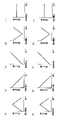
- FIG. 5 is a diagram schematically showing temporal changes in the irradiation light intensity of the first irradiation light and temporal changes in the irradiation light intensity of the second irradiation light.
- FIGS. 5(a), (c), (e), (g) and (i) are diagrams schematically showing temporal changes in the irradiation light intensity of the first irradiation light.
- 5(b), (d), (f), (h) and (j) are diagrams schematically showing temporal changes in the amount of irradiation light of the second irradiation light.
- the irradiation light amount of the first irradiation light may gradually increase as the irradiation time elapses and then gradually decrease as the irradiation time elapses, as shown in FIG. 5(a). Further, the irradiation light amount of the first irradiation light may gradually decrease as the irradiation time elapses, as shown in FIG. 5(c). Further, the irradiation light amount of the first irradiation light may gradually increase as the irradiation time elapses, as shown in FIG. 5(e).
- the irradiation light amount of the first irradiation light may gradually decrease as the irradiation time elapses, and then gradually increase as the irradiation time elapses, as shown in FIG. 5(g). Further, the irradiation light amount of the first irradiation light may be constant from the start of irradiation to the end of irradiation, as shown in FIG. 5(i).
- the irradiation light amount of the second irradiation light may gradually increase as the irradiation time elapses and then gradually decrease as the irradiation time elapses, as shown in FIG. 5(b). Also, the irradiation light amount of the second irradiation light may gradually decrease as the irradiation time elapses, as shown in FIG. 5(d). Further, the irradiation light amount of the second irradiation light may gradually increase as the irradiation time elapses, as shown in FIG. 5(f). Moreover, as shown in FIG.
- the irradiation light amount of the second irradiation light may gradually decrease as the irradiation time elapses and then gradually increase as the irradiation time elapses. Further, the irradiation light amount of the second irradiation light may be constant from the start of irradiation to the end of irradiation, as shown in FIG. 5(j).
- the first irradiation modes shown in FIGS. 5(a), (c), (e), (g) and (i) and FIGS. ), (f), (h), and (j) can be used in appropriate combination with the irradiation modes of the second irradiation light.
- the irradiation mode of the first irradiation light shown in FIG. 5A and the irradiation mode of the second irradiation light shown in FIG. 5F may be used in combination.
- the irradiation mode of the first irradiation light shown in FIG. 5(g) and the irradiation mode of the second irradiation light shown in FIG. 5(f) may be used in combination.
- the irradiation form of the first irradiation light shown in FIG. It is preferable to use it in combination with the irradiation form of the second irradiation light.
- the ridges 5B formed by irradiation with light having a wavelength of 200 nm or less have a finer structure and a finer structure than an uneven shape formed on the surface of the surface protective layer 5 by mechanical processing such as embossing. It's becoming By forming such fine irregularities on the surface of the surface protective layer 5, it is possible to improve fingerprint resistance while maintaining the matte feel of the surface of the decorative sheet 1.
- the layer thickness of the surface protective layer 5 is preferably in the range of 2 ⁇ m or more and 20 ⁇ m or less. More preferably, the layer thickness of the surface protective layer 5 is in the range of 3 ⁇ m or more and 20 ⁇ m or less. More preferably, the layer thickness of the surface protective layer 5 is in the range of 5 ⁇ m or more and 15 ⁇ m or less. Most preferably, the layer thickness of the surface protective layer 5 is in the range of 5 ⁇ m or more and 12 ⁇ m or less. If the layer thickness of the surface protective layer 5 is less than 2 ⁇ m, the shaping by vacuum ultraviolet light cannot be deepened, and the glossiness cannot be reduced.
- the layer thickness of the surface protective layer 5 is such that the ratio of the layer thickness of the ridged portion 5B to the layer thickness of the core portion 5A (layer thickness of the ridged portion 5B/layer thickness of the core portion 5A) is 0.01 or more and 2 It is preferably set to 0.0 or less, and more preferably set to 0.1 or more and 1.0 or less.
- the pattern layer 3 and the surface protective layer 5 can be formed by various printing methods such as gravure printing, offset printing, screen printing, electrostatic printing, and inkjet printing.
- the surface protective layer 5 covers the entire surface of the raw fabric layer 2 on the surface side, it can be coated by various coating methods such as roll coating, knife coating, micro gravure coating, and die coating. can be formed. These printing methods or coating methods may be selected separately depending on the layers to be formed, or the same method may be selected for collective processing.
- the pattern layer 3 and the surface protective layer 5 may be synchronized from the viewpoint of design.
- it is preferable to use the gravure printing method because it is necessary to collectively form the surface protective layer 5 after forming the pattern layer 3 .
- the gravure printing method is advantageous in terms of cost and is preferable because it can handle relatively high speeds.
- the alignment means that 50% or more, preferably 70% or more, and most preferably 90% or more of the portion where the surface protective layer 5 is formed overlaps with the pattern portion of the pattern layer 3 in plan view. do.
- the coating amount may be adjusted in the above-described printing method and coating method.
- the coating amount can be calculated from the difference in mass between a base material (original fabric layer) with and without a surface protective layer formed in various printing methods and coating methods.
- the main material of the surface protective layer 5 is an ionizing radiation curable resin.
- the main material refers to a material containing 60 parts by mass or more, more preferably 70 parts by mass or more, and most preferably 80 parts by mass or more based on 100 parts by mass of the surface protective layer.
- the ionizing radiation curable resin constituting the surface protective layer 5 known ones such as various monomers and commercially available oligomers can be used.
- (meth)acrylic resin silicone resin, polyester resin , urethane-based resins, amide-based resins, and epoxy-based resins
- the ionizing radiation-curable resin may be either a water-based resin or a non-aqueous (organic solvent-based) resin.
- the main component of the ionizing radiation-curable resin that constitutes the surface protective layer 5 is an acrylate resin that includes a repeating structure and has a dipentaerythritol skeleton.
- the ionizing radiation-curable resin constituting the surface protective layer 5 is an acrylate resin (acrylic resin) whose main component is a repeating structure, and the acrylate resin has a dipentaerythritol skeleton. Since the acrylate resin has a dipentaerythritol skeleton, the degree of cross-linking of the acrylate resin increases and a three-dimensional structure can be easily obtained. As a result, the strength of the surface protective layer 5 can be improved.
- acrylate resins having a dipentaerythritol skeleton include dipentaerythritol pentaacrylate and dipentaerythritol hexaacrylate.
- the main component refers to a component containing 60 parts by mass or more, more preferably 70 parts by mass or more, and most preferably 80 parts by mass or more based on 100 parts by mass of the constituent resin component.
- the acrylic resin having a dipentaerythritol skeleton is preferably pentafunctional or hexafunctional. More specifically, the number of acryloyl groups provided on the dipentaerythritol skeleton is preferably 5 or 6.
- the degree of cross-linking is lowered and the scratch resistance is lowered, which is not preferable.
- the number of acryloyl groups in the dipentaerythritol skeleton is 4 or less, the degree of cross-linking of the acrylate resin (acrylic resin) is lowered and the scratch resistance is lowered, which is not preferable.
- the ionizing radiation curable resin has a suitable viscosity range of 10 to 500 mPa ⁇ s and an optimum viscosity range of 50 to 300 mPa ⁇ s when gravure printing is used as the coating method.
- an organic solvent or a low-viscosity bi- to tetra-functional acrylate resin can be added.
- organic solvents Di- to tetra-functional acrylate resins are not preferred because if the amount added is large, the scratch resistance will decrease.
- the content of the di- to tetra-functional acrylate resin is the content of the acrylate resin having a dipentaerythritol skeleton (mass ) is preferably in the range of 10% by mass or more and 30% by mass or less, more preferably in the range of 15% by mass or more and 25% by mass or less.
- the bi- to tetra-functional acrylate resin mentioned above refers to an acrylate resin having 2 to 4 acryloyl groups.
- the repeating structure is any one of an ethylene oxide (EO) structure, a propylene oxide (PO) structure, and an ⁇ -caprolactone (CL) structure. More preferably, the repeating structure is an ethylene oxide structure or a propylene oxide structure.
- the ethylene oxide structure, propylene oxide structure, and ⁇ -caprolactone structure are preferred because the molecules can rotate freely and have high flexibility, so that the molecules are easily folded by light of 200 nm or less, and fine irregularities are easily formed.
- the number of repetitions of this repetition structure is set to 12 or more. It is more preferably 12 or more and 50 or less, and most preferably 16 or more and 50 or less.
- the ionizing radiation curable resin constituting the surface protective layer 5 does not sufficiently shrink when irradiated with vacuum ultraviolet light (VUV light), and the surface protective layer 5 does not become low gloss.
- VUV light vacuum ultraviolet light
- the number of repetitions of the repeating structure can be analyzed by using MALDI-TOF-MS.
- Ionizing radiation curable resins may have a molecular weight distribution. When there is a molecular weight distribution, the number of repetitions is the number of repetitions corresponding to the molecular weight having the strongest peak in the mass spectrum of MALDI-TOF-MS.
- the surface protective layer 5 may contain particles.
- a uniform surface can be formed by adding particles of optimum particle size and optimum content.
- the particles for example, organic materials such as PE wax, PP wax, and resin beads, or inorganic materials such as silica, glass, alumina, titania, zirconia, calcium carbonate, and barium sulfate can be used.
- the average particle size (D50) of the particles is preferably 10 ⁇ m or less. It is more preferably 1 ⁇ m or more and 8 ⁇ m or less, still more preferably 2 ⁇ m or more and 6 ⁇ m or less, and most preferably 3 ⁇ m or more and 5 ⁇ m or less. If it is larger than 10 ⁇ m, the scratch resistance is lowered due to particle shedding, which is not preferable. If the thickness is less than 1 ⁇ m, the effect of making the surface uniform is small, which is not preferable.
- the amount of the particles to be added is preferably 0.5 parts by mass or more and 10 parts by mass or less with respect to 100 parts by mass of the ionizing radiation-curable resin. More preferably, the amount of particles added is 2 to 8 parts by mass, more preferably 2 to 6 parts by mass, and most preferably 4 to 5 parts by mass.
- the surface protective layer 5 can form a uniform surface state by containing the particles in the above-mentioned amount, which is preferable.
- the "particle diameter (average particle diameter)" may be a value (average value) obtained by measuring the particle size distribution of the particles used, or the particle diameters of a plurality of particles obtained by observing the cross section of the obtained decorative material. may be a value obtained by actually measuring and averaging.
- the obtained particle size values are substantially the same.
- the average particle size of the particles added to the surface protective layer 5 may be the median size (D50) measured with a laser diffraction/scattering particle size distribution analyzer.
- the photoinitiator is not particularly limited, examples thereof include benzophenone-based, acetophenone-based, benzoin ether-based, and thioxanthone-based initiators. Functional additives such as antibacterial agents and antifungal agents may optionally be added to the surface protective layer 5 in order to impart required functions. Moreover, an ultraviolet absorber and a light stabilizer can be added to the surface protective layer 5 as necessary. It is common to add UV absorbers such as benzotriazole, benzoate, benzophenone, and triazine, and light stabilizers such as hindered amines in any combination.
- Such a decorative sheet 1 has a glossiness of 5.0 or less, even though it does not contain a glossiness adjusting agent (matting additive), and is a decorative sheet with extremely low glossiness.
- a glossiness adjusting agent such additive
- the content of the gloss modifier in the surface protective layer is high and the surface protective layer becomes cloudy. For this reason, there is a risk that the colors and patterns of the colored pattern layer will not be clearly expressed, or that the design of the decorative sheet will be deteriorated.
- the content of the gloss modifier in the surface protective layer is even higher, so that the surface can be smoothed without causing streaks, unevenness, etc.
- the decorative sheet 1 can provide a low glossiness decorative sheet with a glossiness of 5.0 or less while maintaining the same level of performance as a decorative sheet having a glossiness of 20 or more.
- glossiness is a value measured at an incident angle of 60 degrees using a gloss meter conforming to JIS Z8741.
- the concealing layer 8 can basically be made of the same material as the pattern layer 3. However, since the concealing property is intended, for example, an opaque pigment, titanium oxide, iron oxide, or the like is used as the pigment. is preferred. Moreover, in order to improve hiding power, it is also possible to add metals such as gold, silver, copper and aluminum. In general, flaky aluminum is often added.
- a manufacturing example of the decorative sheet 1 will be described.
- a resin film is used as the original fabric layer 2, and the surface protective layer 5 is formed on the upper surface of the original fabric layer 2 by printing.
- the surface protective layer 5 irradiates the surface of the applied ionizing radiation curable resin with light having a wavelength of 200 nm or less (first irradiation light) to shrink the surface of the ionizing radiation curable resin.
- first irradiation light ionizing radiation or UV light having a longer wavelength than light having a wavelength of 200 nm or less, which is the first irradiation light
- the decorative sheet 1 including the surface protective layer 5 having the core portion 5A and the ridged portion 5B protruding from one surface (upper surface) of the core portion 5A is formed.
- the present embodiment is not limited to the above-described embodiments. UV light with a longer wavelength may be applied only once. Further, at that time, the integrated amount of light having a wavelength of 200 nm or less, which is the first irradiation light, may be set to 0.5 mJ/cm 2 or more and 200 mJ/cm 2 or less.
- the decorative sheet 1 according to this embodiment includes a surface protective layer 5 having an uneven surface.
- the luster (glossiness) of the surface protective layer can be adjusted even if the surface protective layer does not contain a glossiness adjusting agent (matting additive). Since the luster modifier reduces the oil repellency of the layer formed of the resin material, fingerprints tend to stick to it. Since the surface protective layer 5 according to the present embodiment does not contain a luster adjusting agent, it does not absorb oil and has relatively improved oil repellency. Therefore, fingerprints are less likely to adhere to the decorative sheet 1 having the surface protective layer 5 in various situations during site construction, furniture assembly, and residents' daily lives.
- the oil repellency of the surface protective layer 5 is improved, and it is possible to suppress oil stains and adsorption of contaminants on the surface of the decorative sheet 1.
- the structure of the surface protective layer 5 that does not contain the glossiness adjusting agent when the surface of the decorative sheet 1 is scratched, the particles of the glossiness adjusting agent do not come off, and the glossiness of the surface of the decorative sheet 1 changes and scratches occur. It is possible to make it harder.
- the surface protective layer 5 is formed of a single layer in this embodiment, it is not limited to such a structure.
- a structure in which the surface protective layer 5 is multi-layered may be used. That is, the surface protective layer 5 may be formed by laminating a plurality of layers of the same ionizing radiation curable resin or laminating a plurality of layers of different ionizing radiation curable resins to form an uneven shape on the surface.
- the outermost layer of the surface protective layer 5 is made of an ionizing radiation-curable resin as a main material, and the ionizing radiation-curable resin has a repeating structure as a main component.
- An acrylic resin having a dipentaerythritol skeleton containing The layer positioned on the raw fabric layer 2 side of the surface protective layer 5 (that is, the layer positioned below the outermost layer of the surface protective layer 5) is not particularly limited.
- Example 1 A 55 ⁇ m-thick olefin film (manufactured by Riken Technos Co., Ltd.) was used as a base layer, one side of the base layer was subjected to corona treatment, and the following surface protective layer coating liquid was applied to one side.
- the layer thickness of the coating liquid for the surface protective layer was set to 5 ⁇ m.
- the surface of the surface protective layer coating liquid was irradiated with a Xe excimer lamp having a wavelength of 172 nm so that the integrated amount of light was 100 mJ/cm 2 to shrink the surface.
- 100 kGy of ionizing radiation was applied to cure the surface protective layer coating liquid, thereby forming the surface protective layer 5 and obtaining a decorative sheet of Example 1 having a total thickness of 60 ⁇ m.
- the surface protective layer coating liquid was prepared by blending the following particles with the following ionizing radiation curable resin.
- ⁇ Ionizing radiation curable resin Type Ethoxylated dipentaerythritol hexaacrylate (30 moles of EO added)
- Composition 100 parts by mass/particle
- Product name Silysia 250N (manufactured by Fuji Silysia Chemical Co., Ltd.)
- Particle size 5 ⁇ m
- Compounding 0.5 parts by mass
- Example 2 A decorative sheet of Example 2 was obtained in the same manner as in Example 1, except that the ionizing radiation-curable resin of Example 1 was replaced with the following.
- ⁇ Ionizing radiation curable resin Type Ethoxylated dipentaerythritol pentaacrylate (30 moles of EO added)
- Example 3 A decorative sheet of Example 3 was obtained in the same manner as in Example 1, except that the ionizing radiation-curable resin of Example 1 was replaced with the following.
- ⁇ Ionizing radiation curable resin Type Ethoxylated dipentaerythritol hexaacrylate (50 moles of EO added)
- Example 4 A decorative sheet of Example 4 was obtained in the same manner as in Example 1, except that the ionizing radiation-curable resin of Example 1 was replaced with the following.
- ⁇ Ionizing radiation curable resin Type ethoxylated dipentaerythritol hexaacrylate (with EO 12 moles added)
- ⁇ Ionizing radiation curable resin Type Propoxylated dipentaerythritol hexaacrylate (addition of 30 moles of PO)
- Example 6> A decorative sheet of Example 6 was obtained in the same manner as in Example 1, except that the ionizing radiation-curable resin of Example 1 was replaced with the following.
- ⁇ Ionizing radiation curable resin Type Caprolactone-modified dipentaerythritol hexaacrylate (30 moles of CL added)
- Example 7> A decorative sheet of Example 7 having a total thickness of 56 ⁇ m was obtained in the same manner as in Example 1, except that the layer thickness of the surface protective layer coating liquid of Example 1 was changed to 1 ⁇ m.
- Example 8> A decorative sheet of Example 8 having a total thickness of 57 ⁇ m was obtained in the same manner as in Example 1 except that the layer thickness of the surface protective layer coating liquid of Example 1 was changed to 2 ⁇ m.
- Example 9> A decorative sheet of Example 9 having a total thickness of 75 ⁇ m was obtained in the same manner as in Example 1, except that the layer thickness of the surface protective layer coating liquid of Example 1 was changed to 20 ⁇ m.
- Example 10> A decorative sheet of Example 10 having a total thickness of 80 ⁇ m was obtained in the same manner as in Example 1, except that the layer thickness of the surface protective layer coating liquid of Example 1 was changed to 25 ⁇ m.
- Example 11> A decorative sheet of Example 11 was obtained in the same manner as in Example 10, except that the particles of Example 10 were not blended.
- Example 12> A decorative sheet of Example 12 was obtained in the same manner as in Example 1, except that the particles of Example 1 were not blended.
- Example 13> A decorative sheet of Example 13 was obtained in the same manner as in Example 1, except that the particles of Example 1 were replaced with the following.
- ⁇ Example 14> A decorative sheet of Example 14 was obtained in the same manner as in Example 1, except that the particles of Example 1 were replaced with the following.
- Example 15 A decorative sheet of Example 15 was obtained in the same manner as in Example 1, except that the amount of the particles of Example 1 was changed to 10 parts by mass.
- ⁇ Comparative Example 1> A decorative sheet of Comparative Example 1 was obtained in the same manner as in Example 1, except that the excimer lamp irradiation of Example 1 was omitted and the amount of the particles was changed to 15 parts by mass.
- ⁇ Comparative Example 2> A decorative sheet of Comparative Example 2 was obtained in the same manner as in Example 1, except that the ionizing radiation-curable resin of Example 1 was replaced with the following.
- ⁇ Ionizing radiation curable resin Type Ethoxylated pentaerythritol tetraacrylate (35 moles of EO added)
- Comparative Example 3> A decorative sheet of Comparative Example 3 was obtained in the same manner as in Example 1, except that the ionizing radiation-curable resin of Example 1 was replaced with the following.
- ⁇ Ionizing radiation curable resin Type Dipentaerythritol hexaacrylate
- ⁇ Fingerprint resistance evaluation of wiping property>
- a fingerprint wiping off evaluation was performed.
- the 60-degree glossiness of the surface of each decorative sheet was measured and defined as [initial glossiness].
- the anti-fingerprint evaluation liquid adhering to the surface of the decorative sheet was wiped off.
- the 60-degree glossiness of the portion from which the anti-fingerprint evaluation liquid was wiped off was measured and referred to as [glossiness after wiping].
- a higher fatty acid was used as the anti-fingerprint evaluation liquid.
- the fingerprint wiping rate was calculated as follows.
- Fingerprint wiping rate (%) (glossiness after wiping/initial glossiness) x 100
- the evaluation criteria were as follows. ⁇ : 70% or more and less than 250% ⁇ : 50% or more and less than 70%, or 250% or more and less than 300% ⁇ : Less than 50%, or 300% or more
- ⁇ Scratch resistance test steel wool rubbing test> After the obtained decorative sheet was attached to the wooden substrate B using a urethane-based adhesive, a steel wool rubbing test was carried out as a scratch resistance evaluation. A load of 500 g was applied to steel wool, and the sheet was rubbed back and forth 20 times, and scratches on the surface of the decorative sheet and changes in gloss were visually observed. The evaluation criteria were as follows. ⁇ : No scratches or change in gloss on the surface ⁇ : Slight scratches or change in gloss on the surface ⁇ : Significant scratches or change in gloss on the surface
- the decorative sheets of Examples 1 to 18 it is possible to provide a decorative sheet having both anti-fingerprint, anti-scratch and anti-staining properties while having low gloss.
- the layer thickness of the surface protective layer and the particle size and addition amount of the particles to be blended can be optimized to further improve performance.
Landscapes
- Engineering & Computer Science (AREA)
- Architecture (AREA)
- Civil Engineering (AREA)
- Structural Engineering (AREA)
- Physics & Mathematics (AREA)
- Plasma & Fusion (AREA)
- Life Sciences & Earth Sciences (AREA)
- Wood Science & Technology (AREA)
- Laminated Bodies (AREA)
Abstract
Description
意匠性の付与については、木目や石目といった柄を、各種印刷方法を用いて形成したものから、柄の無い無地表面まで、要求や用途に応じて選択される。また同様に、表面の光沢感も意匠性として重要な項目であり、鏡面のような高光沢から映り込みの全くない低光沢まで、要求や用途に応じて選択されるものである。
耐久性の付与には、化粧シートにおける最表面に表面保護層を形成するのが一般的である。また、前述の光沢感を調整するため、特に低光沢を達成するために、表面保護層中に艶調整剤(艶消し添加剤)を添加することが一般的である。
このように、意匠性(低光沢)、耐傷性、耐汚染性が考慮された化粧シートとして、例えば特許文献1に記載の化粧シートがある。
以上の要求に対し、低光沢化については、艶調整剤を高濃度で添加し表面を粗くする方法があるが、多量に添加することで、以下に示すような不具合を生じる。(1)指紋汚れが落ちにくくなり、耐指紋性が低下する。(2)耐傷性試験で艶調整剤が脱離してしまい、耐傷性が低下する。(3)汚れが落ちにくくなり、耐汚染性が低下する。
ここで、図面は模式的なものであり、厚さと平面寸法との関係、各層の厚さの比率等は現実のものとは異なる。また、以下に示す実施形態は、本発明の技術的思想を具体化するための構成を例示するものであって、本発明の技術的思想は、特許請求の範囲に記載された請求項が規定する技術的範囲内において、様々の変更を加えることができる。
本実施形態の化粧シート1は、図1に示すように、原反層(基材層)2の一方の面である表面側に、絵柄層3、接着層7(感熱接着層、アンカーコート層、ドライラミ接着剤層)、透明樹脂層4及び表面保護層5がこの順に積層されて構成される。また、原反層2の他方の面である裏面側に、隠蔽層8及びプライマ層6が設けられている。絵柄層3及び接着層7、透明樹脂層4、隠蔽層8、プライマ層6は省略してもよい。
そして、本実施形態の化粧シート1は、図1に示すように、基板Bに貼り合わされることで化粧材11を構成する。基板Bは、特に限定はないが、例えば、木質ボード類、無機質ボード類、金属板、複数の材料からなる複合板などから構成される。
原反層2としては、例えば紙、合成樹脂、あるいは合成樹脂の発泡体、ゴム、不織布、合成紙、金属箔等から任意に選定したものが使用可能である。紙としては、薄葉紙、チタン紙、樹脂含浸紙等が例示できる。合成樹脂としては、ポリエチレン、ポリプロピレン、ポリブチレン、ポリスチレン、ポリカーボネート、ポリエステル、ポリアミド、エチレン-酢酸ビニル共重合体、ポリビニルアルコール、アクリル等が例示できる。ゴムとしては、エチレン-プロピレン共重合ゴム、エチレン-プロピレン-ジエン共重合ゴム、スチレン-ブタジエン共重合ゴム、スチレン-イソプレン-スチレンブロック共重合ゴム、スチレン-ブタジエン-スチレンブロック共重合ゴム、ポリウレタン等が例示できる。不織布としては、有機系や無機系の不織布が使用できる。金属箔の金属としては、アルミニウム、鉄、金、銀等が例示できる。
プライマ層6としては、後述の絵柄層3と同じ材料を用いることができる。プライマ層6は、化粧シート1の裏面に施されることから、化粧シート1がウエブ状に巻取りされることを考慮すると、ブロッキングを避けて且つ接着剤との密着を高めるために、プライマ層6に無機充填剤を添加させてもよい。無機充填剤としては、シリカ、アルミナ、マグネシア、酸化チタン、硫酸バリウム等が例示できる。
原反層2の層厚は、印刷作業性やコストなどを考慮すれば、20μm以上250μm以下の範囲内が好ましい。
絵柄層3は、原反層2に対してインキを用いて施された絵柄印刷の層である。インキのバインダとしては、例えば、硝化綿、セルロース、塩化ビニル-酢酸ビニル共重合体、ポリビニルブチラール、ポリウレタン、アクリル、ポリエステル系等の単独若しくは各変性物の中から適宜選定して用いることができる。バインダは、水性、溶剤系、エマルジョンタイプのいずれでもよく、また1液タイプでも硬化剤を使用した2液タイプでもよい。更に、硬化性のインキを使用し、紫外線や電子線等の照射によりインキを硬化させる方法を用いてもよい。中でも最も一般的な方法は、ウレタン系のインキを用いるもので、イソシアネートによって硬化させる方法である。絵柄層3に対し、バインダ以外には、例えば、通常のインキに含まれている顔料、染料等の着色剤、体質顔料、溶剤、各種添加剤などが添加されている。汎用性の高い顔料としては、例えば、縮合アゾ、不溶性アゾ、キナクリドン、イソインドリン、アンスラキノン、イミダゾロン、コバルト、フタロシアニン、カーボン、酸化チタン、酸化鉄、雲母等のパール顔料等が挙げられる。
接着層7は、感熱接着層、アンカーコート層、ドライラミ接着剤層とも呼ばれる層である。
接着層7の樹脂材料は特に限定されるものではないが、例えば、アクリル系、ポリエステル系、ポリウレタン系、エポキシ系などの樹脂材料から適宜選択して用いることができる。また、接着層7の樹脂材料として、例えば、エチレン-酢酸ビニル共重合樹脂系接着剤も用いることができる。塗工方法は接着剤の粘度などに応じて適宜選択することができるが、一般的には、グラビアコートが用いられ、絵柄層3の上面に対してグラビアコートによって塗布された後、透明樹脂層4とラミネートするようにされている。なお、接着層7は、透明樹脂層4と絵柄層3との接着強度が十分に得られる場合には、省略することができる。
透明樹脂層4の樹脂材料としては、オレフィン系樹脂が好適に用いられる。オレフィン系樹脂としては、例えば、ポリプロピレン、ポリエチレン、ポリブテンなどの他に、αオレフィン(例えば、プロピレン、1-ブテン、1-ペンテン、1-ヘキセン、1-ヘプテン、1-オクテン、1-ノネン、1-デセン、1-ウンデセン、1-ドデセン、トリデセン、1-テトラデセン、1-ペンタデセン、1-ヘキサデセン、1-ヘプタデセン、1-オクタデセン、1-ノナデセン、1-エイコセン、3-メチル-1-ブテン、3-メチル-1-ペンテン、3-エチル-1-ペンテン、4-メチル-1-ペンテン、4-メチル-1-ヘキセン、4,4-ジメチル-1-ペンテン、4-エチル-1-ヘキセン、3-エチル-1-ヘキセン、9-メチル-1-デセン、11-メチル-1-ドデセン、12-エチル-1-テトラデセンなど)を単独重合あるいは二種類以上共重合させたものや、エチレン・酢酸ビニル共重合体、エチレン・ビニルアルコール共重合体、エチレン・メチルメタクリレート共重合体、エチレン・エチルメタクリレート共重合体、エチレン・ブチルメタクリレート共重合体、エチレン・メチルアクリレート共重合体、エチレン・エチルアクリレート共重合体、エチレン・ブチルアクリレート共重合体などのように、エチレン又はαオレフィンとそれ以外のモノマーとを共重合させたものが挙げられる。
表面保護層5は、コア部5Aとコア部5Aの一方の面から畝状に突出して設けられた畝状部5Bとを有している。これにより、表面保護層5の表面には、凹凸形状が形成されている。
ここで、本実施形態に係る化粧シート1において、「畝状」とは、細長く盛り上がり、平面視で線状に連なった形状であることをいう。畝状部5Bは、平面視で曲線状であっても直線状であっても良いが、化粧シート1表面の耐指紋性の観点から曲線状であることが好ましい。また、本開示において、畝状部5Bは、例えば、表面保護層5の表面に設けられた凹凸形状の最も低い部分から先端までの部分であり、コア部5Aは表面保護層5の畝状部5Bを除く部分をいうものとする。
畝状部5Bは、図3の平面写真に示すように、細長く盛り上がり、平面視で線状に連なった形状となっている。畝状部5Bは、後述するように、電離放射線硬化性樹脂の表面に対して特定波長の光を照射して、電離放射線硬化性樹脂の表面を収縮させることにより形成される。
また、RSm/Raは、最も好ましくは、80以上150以下である。RSm/Raがこの数値範囲内であれば、一般的に市販されている洗浄用スポンジが畝形状の間に侵入しやすくなり、仮に化粧シート表面が汚れた場合であっても、一般的に市販されている洗浄用スポンジを用いて汚れをふき取ることが容易となる。
ここで、Ra及びRSmは、線粗さ計を用いて測定した場合の測定値である(JIS B0601に準拠)。
ここで、「正弦波形状」とは、図4に示すように、畝状部5Bの最も低い位置Cから最も高い位置(頂点)Dに至る線を正弦波で表現可能な形状をいう。
また、隣り合う畝状部5B同士の間(谷間)の形状は、凹状の湾曲形状であってもよい。つまり、畝状部5Bの最も低い位置Cの形状は、凹状の湾曲形状であってもよい。
アクリレートに、第1の照射光として波長200nm以下の光を照射すると、アクリレートは自己励起することが可能である。したがって、アクリレートに200nm以下の光を照射することにより、アクリレートを架橋させることが可能となる。200nm以下の光は、アクリレートにおいて数十~数百nm程度の深さまで到達する。そのため、表面のみ架橋し、その下の部分が流動性を持つため、折畳みシワの様な波状に連なる微細な凹凸形状が生じる。
200nm以下の光は、大気中の酸素に吸収され大きく減衰する。そのため、アクリレートを処理する際には、窒素ガスを導入して反応雰囲気を制御する必要がある。反応雰囲気中の残留酸素濃度は、2000ppm以下に抑えることが好ましい。より好ましくは、反応雰囲気中の残留酸素濃度が1000ppm以下である。
第1の照射光である波長200nm以下の光は、アクリレートにおいて、最表面から数十~数百nm程度の深さにしか到達しないため、200nm以下の光が照射されて形成された畝状部5Bを有する表面保護層5の内部は流動性があり、さらに硬化反応を進めなくてはならない。200nm以下の光を照射した後に表面保護層5を硬化するには、第2の照射光として、電離放射線や第1の照射光である波長200nm以下の光よりも波長が長いUV光を用いることができる。
図5は、第1の照射光の照射光量の時間変化、及び第2の照射光の照射光量の時間変化を模式的に示した図である。
図5(a)、(c)、(e)、(g)及び(i)は、第1の照射光の照射光量の時間変化を模式的に示した図である。また、図5(b)、(d)、(f)、(h)及び(j)は、第2の照射光の照射光量の時間変化を模式的に示した図である。
また、表面保護層5の層厚は、畝状部5Bの層厚とコア部5Aの層厚との比率(畝状部5Bの層厚/コア部5Aの層厚)が0.01以上2.0以下となるように設定することが好ましく、0.1以上1.0以下となるように設定すれば、より好ましい。
表面保護層5は、主材料が電離放射線硬化性樹脂である。ここで、主材料とは、表面保護層100質量部に対し60質量部以上、より好ましくは70質量部以上、最も好ましくは80質量部以上含む材料を指す。表面保護層5を構成する電離放射線硬化性樹脂としては、各種モノマーや市販されているオリゴマーなど、公知のものを用いることができ、例えば、(メタ)アクリル系樹脂、シリコーン系樹脂、ポリエステル系樹脂、ウレタン系樹脂、アミド系樹脂、エポキシ系樹脂を使用できる。電離放射線硬化性樹脂は、水系樹脂又は非水系(有機溶剤系)樹脂の何れであっても良い。
ジペンタエリスリトール骨格を有するアクリル樹脂は、5官能または6官能であることが好ましい。より具体的には、ジペンタエリスリトール骨格に備わるアクリロイル基の数は、5または6であることが好ましい。4官能以下の樹脂の場合、架橋度が低下し、耐傷性が低下するため好ましくない。つまり、ジペンタエリスリトール骨格に備わるアクリロイル基の数が4以下であると、アクリレート樹脂(アクリル樹脂)の架橋度が低下し、耐傷性が低下するため好ましくない。
上記繰り返し構造の繰り返し回数は、MALDI-TOF-MSを使用することで分析可能である。電離放射線硬化性樹脂は、分子量分布を持つ場合がある。分子量分布がある場合、前記繰り返し回数は、MALDI-TOF-MSのマススペクトルの最も強いピークを持つ分子量に相当する繰り返し回数とする。
粒子の平均粒径(D50)は、10μm以下であることが好ましい。より好ましくは、1μm以上8μm以下であり、さらに好ましくは、2μm以上6μm以下であり、最も好ましくは、3μm以上5μm以下である。10μmより大きい場合、粒子脱落による耐傷性の低下が起きるため好ましくない。1μm未満の場合、面を均一化する効果が小さいため好ましくない。
ここで、「粒径(平均粒子径)」とは、用いる粒子の粒度分布測定により得られる値(平均値)としてもよいし、得られた化粧材の断面観察から、複数の粒子の粒径を実測して平均化した値であってもよい。両者は互いに測定手法は異なっているが、得られる粒径の値は実質的に同じものとなる。例えば、表面保護層5に添加される粒子の平均粒子径は、レーザ回折/散乱式粒子径分布測定装置で測定されたメジアン径(D50)であってもよい。
表面保護層5は、要求される機能を付与するために抗菌剤、防カビ剤等の機能性添加剤の添加も任意に行うことができる。また、表面保護層5には、必要に応じて紫外線吸収剤、光安定剤を添加することもできる。紫外線吸収剤としては、例えば、ベンゾトリアゾール系、ベンゾエート系、ベンゾフェノン系、トリアジン系等を、また光安定剤としては、例えば、ヒンダードアミン系等を、任意の組み合わせで添加するのが一般的である。
化粧シート1は、20以上の光沢度を有する化粧シートと同程度の性能を維持したまま、光沢度が5.0以下の低光沢度の化粧シートを得ることができる。ここで、「光沢度」は、JIS Z8741に準拠した光沢度計を用いて入射角60度で測定した場合の測定値である。
また、化粧シート1に基材Bに対する隠蔽性を付与したい場合には、原反層2に着色シートを用いることや、別途不透明な隠蔽層8を設けることで対応可能である。隠蔽層8としては、基本的には絵柄層3と同じ材料から構成することができるが、隠蔽性を目的としているので、顔料としては、例えば不透明な顔料、酸化チタン、酸化鉄等を使用することが好ましい。また隠蔽性を上げるために、例えば、金、銀、銅、アルミ等の金属を添加することも可能である。一般的にはフレーク状のアルミを添加させることが多い。
化粧シート1の製造例について説明する。
原反層2として樹脂フィルムを用い、原反層2の上面に表面保護層5を印刷によって成形する。表面保護層5は、塗布された電離放射線硬化性樹脂の表面に対して波長200nm以下の光(第1の照射光)を照射して電離放射線硬化性樹脂の表面を収縮させる。続いて、収縮させた電離放射線硬化性樹脂を硬化させるため、電離放射線または第1の照射光である波長200nm以下の光よりも波長が長いUV光を照射する。以上により、コア部5Aとコア部5Aの一方の面(上面)から畝状に突出して設けられた畝状部5Bとを有する表面保護層5を備える化粧シート1が形成される。
なお、本実施形態は、上述した実施形態に限定されるものではなく、例えば、収縮させた電離放射線硬化性樹脂を硬化させるため、電離放射線、または第1の照射光である波長200nm以下の光よりも波長が長いUV光を1回だけ照射してもよい。また、その際、第1の照射光である波長200nm以下の光の積算光量を0.5mJ/cm2以上200mJ/cm2以下としてもよい。
本実施形態に係る化粧シート1は、表面に凹凸形状が形成された表面保護層5を備えている。この構成によれば、表面保護層に艶調整剤(艶消し添加剤)を含まなくても、表面保護層の艶(光沢度)を調整することができる。艶調整剤は、樹脂材料により形成した層の撥油性を低下させるため、指紋が付きやすくなる。本実施形態に係る表面保護層5は、艶調整剤を含まないため、油を吸収せず相対的に撥油性が向上する。このため、現場施工時や家具組立て時、居住者の日常生活時の様々な場面において、表面保護層5を有する化粧シート1には、指紋が付着しにくくなる。
また、艶調整剤を含まない表面保護層5の構成によれば、化粧シート1の表面を引っ掻いた際に艶調整剤の粒子が脱落せず、化粧シート1表面の艶変化や引っ掻き傷を生じにくくすることが可能である。
以下に、本発明に基づく実施例について説明する。
<実施例1>
厚さ55μmのオレフィンフィルム(リケンテクノス社製)を原反層とし、原反層の一方の面にコロナ処理を施し、その一方の面に対して、下記の表面保護層用塗液を塗布した。表面保護層用塗液の層厚は、5μmとした。その後、表面保護層用塗液の表面に対して波長172nmのXeエキシマランプを積算光量が100mJ/cm2となるように照射し表面を収縮させた。続いて、電離放射線を100kGy照射し、表面保護層用塗液を硬化することで、表面保護層5を形成し、総厚60μmからなる実施例1の化粧シートを得た。
表面保護層用塗液は、下記の電離放射線硬化性樹脂に、下記の粒子を配合して構成した。
・電離放射線硬化性樹脂
種類:エトキシ化ジペンタエリスリトールヘキサアクリレート(EO30モル付加)
配合:100質量部
・粒子
品名:サイリシア250N(富士シリシア化学社製)
粒径:5μm
配合:0.5質量部
実施例1の電離放射線硬化性樹脂を下記に置き換えた以外は、全て実施例1と同様にして実施例2の化粧シートを得た。
・電離放射線硬化性樹脂
種類:エトキシ化ジペンタエリスリトールペンタアクリレート(EO30モル付加)
<実施例3>
実施例1の電離放射線硬化性樹脂を下記に置き換えた以外は、全て実施例1と同様にして実施例3の化粧シートを得た。
・電離放射線硬化性樹脂
種類:エトキシ化ジペンタエリスリトールヘキサアクリレート(EO50モル付加)
実施例1の電離放射線硬化性樹脂を下記に置き換えた以外は、全て実施例1と同様にして実施例4の化粧シートを得た。
・電離放射線硬化性樹脂
種類:エトキシ化ジペンタエリスリトールヘキサアクリレート(EO12モル付加)
<実施例5>
実施例1の電離放射線硬化性樹脂を下記に置き換えた以外は、全て実施例1と同様にして実施例5の化粧シートを得た。
・電離放射線硬化性樹脂
種類:プロポキシ化ジペンタエリスリトールヘキサアクリレート(PO30モル付加)
<実施例6>
実施例1の電離放射線硬化性樹脂を下記に置き換えた以外は、全て実施例1と同様にして実施例6の化粧シートを得た。
・電離放射線硬化性樹脂
種類:カプロラクトン変性ジペンタエリスリトールヘキサアクリレート(CL30モル付加)
実施例1の表面保護層用塗液の層厚を1μmとした以外は、全て実施例1と同様にして、総厚56μmからなる実施例7の化粧シートを得た。
<実施例8>
実施例1の表面保護層用塗液の層厚を2μmとした以外は、全て実施例1と同様にして、総厚57μmからなる実施例8の化粧シートを得た。
<実施例9>
実施例1の表面保護層用塗液の層厚を20μmとした以外は、全て実施例1と同様にして、総厚75μmからなる実施例9の化粧シートを得た。
<実施例10>
実施例1の表面保護層用塗液の層厚を25μmとした以外は、全て実施例1と同様にして、総厚80μmからなる実施例10の化粧シートを得た。
実施例10の粒子を配合なしとした以外は、全て実施例10と同様にして実施例11の化粧シートを得た。
<実施例12>
実施例1の粒子を配合なしとした以外は、全て実施例1と同様にして実施例12の化粧シートを得た。
実施例1の粒子を下記に置き換えた以外は、全て実施例1と同様にして実施例13の化粧シートを得た。
・粒子
品名:サイリシア450(富士シリシア化学社製)
粒径:8.0μm
配合:0.5質量部
<実施例14>
実施例1の粒子を下記に置き換えた以外は、全て実施例1と同様にして実施例14の化粧シートを得た。
・粒子
品名:サイリシア780(富士シリシア化学社製)
粒径:11.3μm
配合:0.5質量部
実施例1の粒子の配合量を10質量部とした以外は、全て実施例1と同様にして実施例15の化粧シートを得た。
<実施例16>
実施例1の粒子の配合量を11質量部とした以外は、全て実施例1と同様にして実施例16の化粧シートを得た。
<実施例17>
実施例1の表面保護層用塗液の層厚を1μmとし、粒子をなしとした以外は、全て実施例1と同様にして、総厚56μmからなる実施例17の化粧シートを得た。
<実施例18>
実施例3の表面保護層用塗液の層厚を25μmとした以外は、全て実施例3と同様にして、総厚80μmからなる実施例18の化粧シートを得た。
実施例1のエキシマランプ照射をなくし、粒子の配合量を15質量部とした以外は、全て実施例1と同様にして比較例1の化粧シートを得た。
<比較例2>
実施例1の電離放射線硬化性樹脂を下記に置き換えた以外は、全て実施例1と同様にして比較例2の化粧シートを得た。
・電離放射線硬化性樹脂
種類:エトキシ化ペンタエリスリトールテトラアクリレート(EO35モル付加)
<比較例3>
実施例1の電離放射線硬化性樹脂を下記に置き換えた以外は、全て実施例1と同様にして比較例3の化粧シートを得た。
・電離放射線硬化性樹脂
種類:ジペンタエリスリトールヘキサアクリレート
上記の方法により得られた実施例1~18及び比較例1~3の化粧シートについて評価を行った。
本実施例において「○」及び「△」の評価であれば、実際に使用する上で問題がないため、合格とした。
<面状態>
面状態は、目視にて、面の均一性を評価した。
評価基準は下記のとおりとした。
〇:均一な面状態
△:一部に、不均一な部分あり
×:全面不均一な面状態
<光沢度>
光沢度は、Rhopoint IQ(コニカミノルタ社製)を用いて、60度光沢度を測定した。表1及び表2では、この60度光沢度を「60°光沢値」としてそれぞれ表記した。
なお、光沢度が15以下であれば、十分に低光沢と視認されるため、本実施例では「15以下」を合格とした。
耐指紋性評価として、指紋のふき取り性評価を実施した。
各化粧シートの表面の60度光沢度を測定して、[初期光沢度]とした。続いて、表面保護層上に耐指紋評価液を付着させた後、化粧シート表面に付着した耐指紋評価液を拭き取った。その後、耐指紋評価液を拭き取った部分の60度光沢度を測定して、[拭き取り後光沢度]とした。ここで、耐指紋評価液として、高級脂肪酸を用いた。
指紋拭き取り率は、下記のとおり算出した。
指紋拭き取り率(%)=(拭き取り後光沢度/初期光沢度)×100
評価基準は、下記の通りとした。
〇:70%以上250%未満
△:50%以上70%未満、もしくは250%以上300%未満
×:50%未満、もしくは300%以上
耐汚染性評価として、日本農林規格(JAS:Japanese Agricultural Standards)に規定する汚染A試験により、青色インキ、黒色速乾性インキ及び赤色クレヨンでそれぞれ幅10mmの線を引き、4時間放置した後、エタノールを布に含ませて青色インキ、黒色速乾性インキ及び赤色クレヨンの線を拭き取り、インキによる耐汚染性を評価した。
評価基準は、下記の通りとした。
〇:各色の線を容易に拭き取ることができた
△:各色の線の一部を拭き取ることができるが、一部に汚れが残る
×:各色の線を拭き取ることができない
得られた化粧シートをウレタン系の接着剤を用いて木質基板Bに貼り付けた後、耐傷性評価として、スチールウールラビング試験を実施した。スチールウールに500gの荷重をかけて20往復擦り、化粧シート表面に生じた傷や光沢の変化を目視にて確認した。
評価基準は、下記の通りとした。
〇:表面に傷や光沢の変化が発生しない
△:表面に軽微な傷や光沢の変化が発生した
×:表面に著しい傷や光沢の変化が発生した
得られた化粧シートをウレタン系の接着剤を用いて木質基板Bに貼り付けた後、耐傷性評価として、鉛筆硬度試験を実施した。試験方法はJIS-K5600に準拠し、4B、3B、2B、B、HB、F、H、2H、3Hの鉛筆を用い、化粧シートに対して鉛筆の角度を45±1°に固定して、当該鉛筆に750gの荷重を負荷した状態でスライドさせて、化粧シートに傷が形成されるか否かの目視にて確認した。評価結果として、表1には、化粧シートの表面に傷が付かない最高硬度の鉛筆硬度を表示した。
なお、最高硬度が「H」、「2H」、「3H」であれば合格とした。
評価結果を、表1及び表2に示す。


2 原反層
3 絵柄層
4 透明樹脂層
5 表面保護層
6 プライマ層
7 接着層
8 隠蔽層
11 化粧材
B 基板
Claims (16)
- 原反層と、前記原反層の一方の表面に設けられた表面保護層と、を備え、
前記表面保護層は、その表面に、畝状に突出して設けられた畝状部を有し、凹凸形状が形成されており、
前記表面保護層の前記凹凸形状のRSm/Raは、10以上300以下の範囲内であり、
前記表面保護層は、主材料が電離放射線硬化性樹脂であり、
前記電離放射線硬化性樹脂は、主成分が繰り返し構造を含むアクリル樹脂であり、
前記アクリル樹脂は、ジペンタエリスリトール骨格を有し、
前記繰り返し構造は、エチレンオキサイド、プロピレンオキサイド、及びε-カプロラクトンの各構造のうちいずれかであり、
前記繰り返し構造の繰り返し回数は、12以上であることを特徴とする化粧シート。 - 前記表面保護層の厚さは、2μm以上20μm以下の範囲内であることを特徴とする請求項1に記載の化粧シート。
- 前記表面保護層は、平均粒径が10μm以下の粒子を含むことを特徴とする請求項2に記載の化粧シート。
- 前記粒子の添加量が、前記電離放射線硬化性樹脂100質量部に対して、0.5質量部以上10質量部以下の範囲内であることを特徴とする請求項3に記載の化粧シート。
- 前記ジペンタエリスリトール骨格に備わるアクリロイル基の数が5または6であることを特徴とする請求項1から請求項4のいずれかに記載の化粧シート。
- 前記表面保護層の光沢度は、5.0以下であることを特徴とする請求項1から請求項5のいずれかに記載の化粧シート。
- 前記表面保護層は、コア部と、前記コア部上に形成された前記畝状部とを備え、
前記畝状部の層厚と、前記コア部の層厚との比率(畝状部の層厚/コア部の層厚)は、0.01以上2.0以下の範囲内であることを特徴とする請求項1から請求項6のいずれかに記載の化粧シート。 - 前記表面保護層は、コア部と、前記コア部上に形成された前記畝状部とを備え、
前記畝状部の層厚と、前記コア部の層厚との比率(畝状部の層厚/コア部の層厚)は、0.1以上1.0以下の範囲内であることを特徴とする請求項1から請求項6のいずれかに記載の化粧シート。 - 前記表面保護層の前記凹凸形状のRSm/Raは、80以上150以下の範囲内であることを特徴とする請求項1から請求項8のいずれかに記載の化粧シート。
- 前記畝状部の前記表面保護層の厚さ方向における断面形状は、正弦波形状であることを特徴とする請求項1から請求項9のいずれかに記載の化粧シート。
- 塗布された電離放射線硬化性樹脂の表面に対して、波長200nm以下の光を照射した後に、電離放射線、または前記波長200nm以下の光よりも波長が長いUV光を照射することで、
畝状に突出した畝状部を有する表面保護層を形成することを特徴とする化粧シートの製造方法。 - 前記波長200nm以下の光は、波長172nmであることを特徴とする請求項11に記載の化粧シートの製造方法。
- 塗布された電離放射線硬化性樹脂の表面に対して、波長200nm以下の光を照射した後に、電離放射線、または前記波長200nm以下の光よりも波長が長いUV光を1回照射することのみで、
畝状に突出した畝状部を有する表面保護層を形成し、
前記波長200nm以下の光の積算光量を0.5mJ/cm2以上200mJ/cm2以下の範囲内とすることを特徴とする請求項11または請求項12に記載の化粧シートの製造方法。 - 前記波長200nm以下の光よりも波長が長いUV光の積算光量を10mJ/cm2以上500mJ/cm2以下の範囲内とすることを特徴とする請求項11から請求項13のいずれか1項に記載の化粧シートの製造方法。
- 塗布された電離放射線硬化性樹脂の表面に対して、波長200nm以下の光を照射した後に、電離放射線を照射することで、
畝状に突出した畝状部を有する表面保護層を形成することを特徴とする請求項11または請求項12に記載の化粧シートの製造方法。 - 粘度範囲が10mPa・s以上500mPa・s以下である前記電離放射線硬化性樹脂を塗布することを特徴とする請求項11から請求項15のいずれか1項に記載の化粧シートの製造方法。
Priority Applications (5)
| Application Number | Priority Date | Filing Date | Title |
|---|---|---|---|
| JP2023533169A JPWO2023282295A1 (ja) | 2021-07-06 | 2022-07-06 | |
| KR1020237043222A KR20240031961A (ko) | 2021-07-06 | 2022-07-06 | 화장 시트 및 화장 시트의 제조 방법 |
| CN202280044585.XA CN117545630A (zh) | 2021-07-06 | 2022-07-06 | 装饰片以及装饰片的制造方法 |
| EP22837709.9A EP4368389A1 (en) | 2021-07-06 | 2022-07-06 | Decorative sheet and production method for decorative sheet |
| US18/403,365 US20240173937A1 (en) | 2021-07-06 | 2024-01-03 | Decorative sheet and method for producing decorative sheet |
Applications Claiming Priority (2)
| Application Number | Priority Date | Filing Date | Title |
|---|---|---|---|
| JP2021112085 | 2021-07-06 | ||
| JP2021-112085 | 2021-07-06 |
Related Child Applications (1)
| Application Number | Title | Priority Date | Filing Date |
|---|---|---|---|
| US18/403,365 Continuation US20240173937A1 (en) | 2021-07-06 | 2024-01-03 | Decorative sheet and method for producing decorative sheet |
Publications (1)
| Publication Number | Publication Date |
|---|---|
| WO2023282295A1 true WO2023282295A1 (ja) | 2023-01-12 |
Family
ID=84810965
Family Applications (1)
| Application Number | Title | Priority Date | Filing Date |
|---|---|---|---|
| PCT/JP2022/026859 WO2023282295A1 (ja) | 2021-07-06 | 2022-07-06 | 化粧シート、及び化粧シートの製造方法 |
Country Status (6)
| Country | Link |
|---|---|
| US (1) | US20240173937A1 (ja) |
| EP (1) | EP4368389A1 (ja) |
| JP (1) | JPWO2023282295A1 (ja) |
| KR (1) | KR20240031961A (ja) |
| CN (1) | CN117545630A (ja) |
| WO (1) | WO2023282295A1 (ja) |
Citations (5)
| Publication number | Priority date | Publication date | Assignee | Title |
|---|---|---|---|---|
| JP2004167779A (ja) * | 2002-11-19 | 2004-06-17 | Dainippon Printing Co Ltd | 化粧材及びその製造方法 |
| JP2018184583A (ja) * | 2017-02-07 | 2018-11-22 | Dicグラフィックス株式会社 | コーティング組成物、及びこれを用いた化粧シート |
| JP2019151739A (ja) * | 2018-03-02 | 2019-09-12 | 岩崎電気株式会社 | 樹脂硬化方法、及び樹脂硬化装置 |
| JP2021013887A (ja) * | 2019-07-11 | 2021-02-12 | Dicグラフィックス株式会社 | 塗装建材の製造方法、及び得られた塗装建材 |
| JP2021024102A (ja) * | 2019-07-31 | 2021-02-22 | タキロンシーアイ株式会社 | 化粧シート及びその製造方法 |
Family Cites Families (1)
| Publication number | Priority date | Publication date | Assignee | Title |
|---|---|---|---|---|
| JP7003667B2 (ja) | 2018-01-05 | 2022-02-10 | 凸版印刷株式会社 | 化粧材 |
-
2022
- 2022-07-06 CN CN202280044585.XA patent/CN117545630A/zh active Pending
- 2022-07-06 WO PCT/JP2022/026859 patent/WO2023282295A1/ja active Application Filing
- 2022-07-06 EP EP22837709.9A patent/EP4368389A1/en active Pending
- 2022-07-06 KR KR1020237043222A patent/KR20240031961A/ko unknown
- 2022-07-06 JP JP2023533169A patent/JPWO2023282295A1/ja active Pending
-
2024
- 2024-01-03 US US18/403,365 patent/US20240173937A1/en active Pending
Patent Citations (5)
| Publication number | Priority date | Publication date | Assignee | Title |
|---|---|---|---|---|
| JP2004167779A (ja) * | 2002-11-19 | 2004-06-17 | Dainippon Printing Co Ltd | 化粧材及びその製造方法 |
| JP2018184583A (ja) * | 2017-02-07 | 2018-11-22 | Dicグラフィックス株式会社 | コーティング組成物、及びこれを用いた化粧シート |
| JP2019151739A (ja) * | 2018-03-02 | 2019-09-12 | 岩崎電気株式会社 | 樹脂硬化方法、及び樹脂硬化装置 |
| JP2021013887A (ja) * | 2019-07-11 | 2021-02-12 | Dicグラフィックス株式会社 | 塗装建材の製造方法、及び得られた塗装建材 |
| JP2021024102A (ja) * | 2019-07-31 | 2021-02-22 | タキロンシーアイ株式会社 | 化粧シート及びその製造方法 |
Also Published As
| Publication number | Publication date |
|---|---|
| US20240173937A1 (en) | 2024-05-30 |
| CN117545630A (zh) | 2024-02-09 |
| JPWO2023282295A1 (ja) | 2023-01-12 |
| KR20240031961A (ko) | 2024-03-08 |
| EP4368389A1 (en) | 2024-05-15 |
Similar Documents
| Publication | Publication Date | Title |
|---|---|---|
| WO2022239270A1 (ja) | 化粧シート、及び化粧シートの製造方法 | |
| WO2022145137A1 (ja) | 化粧シート、及び化粧シートの製造方法 | |
| JP4658749B2 (ja) | 耐衝撃性及び耐スクラッチ性に優れた床材用化粧シート | |
| JP5429129B2 (ja) | 耐衝撃性及び耐スクラッチ性に優れた床材用化粧シート | |
| JP5691150B2 (ja) | 床材用化粧シート及び床用化粧材 | |
| WO2023106340A1 (ja) | 化粧シート、及び化粧シートの製造方法 | |
| JP5176640B2 (ja) | 床材用化粧シート及び床用化粧材 | |
| JP2011067975A (ja) | 化粧シート及び化粧材 | |
| WO2023282295A1 (ja) | 化粧シート、及び化粧シートの製造方法 | |
| WO2023136304A1 (ja) | 化粧シート、及び化粧シートの製造方法 | |
| JP4546306B2 (ja) | 壁装用化粧シート | |
| WO2023095914A1 (ja) | 化粧シート、及び化粧シートの製造方法 | |
| JP5699510B2 (ja) | 床用化粧材 | |
| WO2023191052A1 (ja) | 化粧シート、及び化粧シートの製造方法 | |
| WO2023171805A1 (ja) | 化粧シート、及び化粧シートの製造方法 | |
| JP6963273B2 (ja) | 化粧シート及び化粧シートの製造方法 | |
| WO2023238893A1 (ja) | 化粧シート、及び化粧シートの製造方法 | |
| WO2023224115A1 (ja) | 化粧シート、及び化粧シートの製造方法 | |
| WO2024019096A1 (ja) | 化粧シート及び化粧シートの製造方法 | |
| RU2684368C2 (ru) | Ламинированный лист и вспененный ламинированный лист и их способ производства и способ применения | |
| WO2023249080A1 (ja) | 化粧シート | |
| WO2023249081A1 (ja) | 化粧シート | |
| WO2023249082A1 (ja) | 化粧シート | |
| WO2024010066A1 (ja) | 化粧シート及び化粧シートの製造方法 | |
| JP6707820B2 (ja) | 化粧シート及び化粧板 |
Legal Events
| Date | Code | Title | Description |
|---|---|---|---|
| 121 | Ep: the epo has been informed by wipo that ep was designated in this application |
Ref document number: 22837709 Country of ref document: EP Kind code of ref document: A1 |
|
| WWE | Wipo information: entry into national phase |
Ref document number: 2023533169 Country of ref document: JP |
|
| WWE | Wipo information: entry into national phase |
Ref document number: 202280044585.X Country of ref document: CN |
|
| WWE | Wipo information: entry into national phase |
Ref document number: 2022837709 Country of ref document: EP |
|
| NENP | Non-entry into the national phase |
Ref country code: DE |
|
| ENP | Entry into the national phase |
Ref document number: 2022837709 Country of ref document: EP Effective date: 20240206 |